User Manual. Platinum Modular E Online UPS. Uninterruptible Power Supply System. Designed by Australians for Australian Conditions. Version: 1.
|
|
|
- Milton Heath
- 6 years ago
- Views:
Transcription


1 User Manual Platinum Modular E Online UPS Designed by Australians for Australian Conditions Uninterruptible Power Supply System Version: 1.0
2 Table of Contents 1. Safety Important Safety Instructions EMC Installation information Maintenance Recycling the used battery Operation & structure Installation Mechanism and Exterior Mechanical Data Other Views Configurations Internal Mechanisms Input, Maintenance Bypass and Output Breakers Wiring Modules Control Panel & interface LED indications LCD Display Function Keys Installation and Wiring Before Installation Installation Environment Transportation Unpacking Positioning Modules Power Module Install a Power Module Remove a Power Module Power Cable AC input and maximum output current and power cable configuration DC input maximum current and power cable configuration Control Panel and Display Description Introduction Screen Description Start Screen Main Screen Menu Screen Control Screen Measurement Screen Setup Screen Information Screen Events Screen Alarm List... 38
3 5. Interface and Communication Battery Cabinet Temperature Detection Port Remote EPO Input Port Other Communication Interface Maintenance Replacement Procedures Of Power Module Notes Power Module Replacement Procedures Specifications Conformity And Standards Environmental Characteristics Mechanical Characteristics Electrical Characteristics (Input Rectifier) Electrical Characteristics (Intermediate DC Circuit) Electrical Characteristics (Inverter Output) Electrical Characteristics (Bypass Mains Input)... 46
4 1. Safety 1.1 Important Safety Instructions This UPS contains LETHAL VOLTAGES. All repairs and service must be performed by AUTHORIZED SERVICE PERSONNEL ONLY. There are NO USER SERVICEABLE PARTS inside the UPS. WARNING: The UPS designed for commercial and industrial purpose, it is forbidden to apply for any life sustainment and support. The UPS system contains its own energy source. The output terminals may carry live voltage even when UPS is disconnected from an AC source. To reduce the risk of fire or electrical shock, UPS installation has to be in a temperature and humidity controlled, indoor environment. Ambient temperature must not exceed 40 C. The system is not intended for outdoor use. Ensure all power is disconnected before performing installation or service. Service and maintenance should be performed by qualified service personnel only. Before working on this circuit - Isolate Uninterruptible Power System (UPS) - Then check for Hazardous Voltage between all terminals including the protective earth. Risk of Voltage Backfeed The isolation device must be able to carry the UPS input current. 1.2 EMC WARNING: This is a product for commercial and industrial application in the controlled environment - installation restrictions or additional measures is necessary to prevent disturbances. 1.3 Installation information WARNING: Installation must be performed by qualified personnel only. The cabinets must be installed on a level floor suitable for computer or electronic equipment. The UPS cabinet is heavy. If unloading instructions are not closely followed, cabinet may cause serious injury. Do not tilt the cabinets more than 10. Ground conductor is properly installed. Installation and Wiring must be performed in accordance with the local electrical laws and regulations. The disconnection device should break line and neutral conductors- four poles for three phases. 1
5 1.4 Maintenance UPS is designed to supply power even when disconnected from the utility power. After disconnecting the utility and DC power, authorized service personnel should attempt internal access to the UPS. Only qualified service personnel can perform the battery installation. Do not disconnect the batteries while the UPS is in Battery mode. Disconnect the charging source prior to connecting or disconnecting terminals. Batteries can present a risk of electrical shock or burn from high short circuit current. The following PRECAUTIONS should be stringently observed 1. Remove watches, rings, or other metal objects. 2. Use tools with insulated handles. 3. Wear rubber gloves and boots. 4. Do not lay tools or metal parts on top of batteries or battery cabinets. 5. Disconnect the charging source prior to connecting or disconnecting terminal. 6. Check if the battery is inadvertently grounded. If it is, remove the source of the ground. Contact with any part of a grounded battery can result in electrical shock. The likelihood of such shock is reduced if such grounds are removed during installation and maintenance. When replacing batteries, use the same number of sealed, lead-acid batteries. Do not dispose of battery in a fire. The battery may explode. Do not open or mutilate the battery. Leaking electrolyte is harmful to the skin and eyes, and may be toxic. 1.5 Recycling the used battery Do not dispose of the battery in a fire. Battery may explode. Proper disposal of battery is required. Refer to your local regulations for disposal requirements. Do not open or mutilate the battery. Leaking electrolyte is harmful to the skin and eyes. It may be toxic. Do not discard the UPS or the UPS batteries in the trash. This product contains sealed, lead-acid batteries and must be disposed of properly. For more information, contact your local recycling/reuse or hazardous waste center. Do not discard waste electrical or electronic equipment (WEEE) in the trash. For proper disposal, contact your local recycling/reuse or hazardous waste center. 2

6 2. Operation & structure Figure 2-1: Wiring diagram Figure 2-2: Wire connections for Input and Maintenance Bypass NOTE: Connect 3 wires between Mains and Maintenance Breakers as Figure 2-2 3
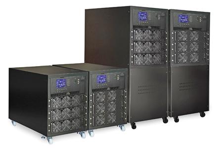
7 3. Installation 3.1 Mechanism and Exterior In the front of the UPS, there are control interface (LCD Panel). Inside the cabinet, there are an STS, 1~3 Power Module slots. All wiring terminal blocks are allocated in the back of system. The side panels are locked by screws. The casters at the bottom of the UPS cabinet can be used to move the cabinet over a short distance. There are two leveling feet to fix and stabilize the UPS cabinet on the ground. Figure 3-1: UPS Exterior 4
8 3.1.1 Mechanical Data Dimensions UPS cabinet Width Depth Height 30~90KW 515mm 1000mm 760mm Figure 3-2: Dimensions 5

9 3.1.2 Other Views At front side, you ll see the Power Module and control interface (LCD Panel). At rear side, you ll the Switch unit (Main/Maintenance Bypass/Output) Front View Rear View LCD Panel 2. Control interface 3. Power module 4. Switch unit Figure 3-3: Front and Rear View 6


10 3.1.3 Configurations Photo Cabinet Height 760mm 760mm Switch Unit 1 1 Max. Power Module 3 (30K) 3 (20K) Max. Power Capacity 90KVA 60KVA Table 3-1: Configuration 7
11 3.2 Internal Mechanisms At front of the cabinet, you can see the control interface (LCD Panel), Power module. A rear of the cabinet, you can see Main/Maintenance Bypass/Output breakers. Please refer to the following sections Input, Maintenance Bypass and Output Breakers The Input Breaker, Maintenance Bypass Breaker and Output Breaker are located at the rear of the UPS. See Figure 3-4. Figure 3-4: Rear View/Output, Maintenance Bypass, and Input Breakers 8
12 3.2.2 Wiring Open the back doors of UPS and you will see the Breakers. For connection instructions, please refer to Figure 3-5. Item Function Description Output Block Connects the critical loads Includes R, S, T and Neutral terminals. Bypass Input Block Connects bypass AC source Includes R, S, T and Neutral terminals. Input Block Connects main AC source Includes R, S, T and Neutral terminals. For UPS Grounding For UPS grounding Includes one grounding terminal. Battery Input Block Connects an external battery cabinet Includes Positive (+), Negative (-) and Neutral (N) terminals. Figure 3-5: Rear View & Wiring Terminal Block 9

13 3.2.3 Modules The Power Module allows quick maintenance, replacement and expansion. The module latches secure the modules in place. Control Module: It includes control, power, communication circuits, an internal Static Transfer Switch. Power Module: The power module capacity is either 30kVA/30kW or 20kVA/ 20kW. It includes a power factor correction rectifier, a battery charger, an inverter and control circuits. 1. STS & Control module 2. Power module 3. Switch Unit Figure 3-6: Front View with Modules 10
14 3.3 Control Panel & interface The front access Graphic Display & Control interface displays all measured parameter, UPS & Battery current states and Alarms. Through the interface, users can easily monitor the status and configure settings. For detailed information, please refer to Chapter 4. Figure 3-7: Control Panel LED indications LED Color Status Definition INPUT BYPASS INVERTER BATTERY ALARM Green Green Green Yellow Red On Flashing Off On Flashing Off On Off On Flashing Off On Flashing Off Input source is normal. Input source is abnormal. No input source Load on Bypass. Input source is abnormal. Bypass not operating Load on inverters. Inverters not operating. Load on Battery. Low battery Battery converter is normal and battery is charging. UPS fault. UPS alarm. Normal LCD Display Graphic display and all measured parameters. 11
15 3.3.3 Function Keys Control Key Description Esc Up(Left) Down(Right) Enter Home Power On/Off Return to previous screen. When screen is in Main screen, it will enter setting menu by pressing ESC key. Return back to change previous value in the same row. For example, if in the process of changing 4-digit password, press Esc to allow cursor back to previous digit. Key for menu page navigation or digit modification. Key for menu page navigation or digit modification. Confirmation of commands, or cursor displacement. Return to Main screen. Turn on UPS or Turn off UPS. 3.4 Installation and Wiring Before Installation Due to different installation environments, please read this user manual thoroughly before installation and wiring. Only authorized engineers or service personnel can perform installation and maintenance. If you want to install the UPS by yourself, installation must be under the supervision of authorized engineers or service personnel. If you use a forklift or other equipment to move the UPS, please make sure its loading capacity is sufficient enough to lift the UPS Installation Environment The UPS is designed for indoor use only. Do not install or place it in an outdoor area. Make sure that transportation routes (e.g. corridor, door gate, elevator, etc.) and installation area can accommodate and bear the weight of the UPS, the external battery cabinet and handling equipment. Ensure that the installation area is big enough for maintenance and ventilation. Keep the ambient temperature of installation around 30 C and that of humidity within 90%. The highest operating altitude is 2000 meters above sea level. The UPS is intended for indoor installation and should be placed in an environment with clean air and with adequate ventilation to keep the ambient temperature within the specified operating range. The UPS is air-cooled with the aid of internal fans. Cold air enters the UPS through the ventilation grilles at the front of the cabinet. If necessary, install a system of room extractor fans to avoid the room temperature heating up. Air filters are necessary if the UPS is operated in a dusty environment. Note: The UPS is suitable for mounting on concrete or other non-combustible surface only. The UPS is air-cooled with the aid of internal fans. Cold air enters the UPS through the ventilation grilles at the front of the cabinet and hot air is released through the grilles at the back. Do not cover the ventilation openings. Do not allow unauthorized personnel to enter the installation area. Assign specific personnel to keep the UPS key. For safety concerns, we suggest that you shall: 1. Surroundings of the installation area with CO2 or dry powder fire extinguishers. 2. Install the UPS in an area where the walls, floors and ceilings were constructed by fireproof 12
16 materials. It is recommended that you parallel the external battery cabinets to the UPS. The following clearances are suggested: 1. Keep a clearance of 100cm from the top of the UPS for maintenance, wiring and ventilation. 2. Keep a clearance of 100cm from the back of the UPS and the external battery cabinets for ventilation. 3. Keep a clearance of a 150cm from the front of the UPS and the external battery cabinets for maintenance and ventilation Transportation Warning The UPS is fixed on the pallet with four balance supports. When removing them, pay attention to the movement of the casters to avoid accidents. The cabinet can be pushed forward or backward only. Pushing it sideward is not allowed. When pushing the cabinet, take care not to overturn it as the gravity center is high. If you need to move the UPS over a long distance, please use appropriate equipment like a forklift. Do not use the UPS casters to move the UPS over a long distance. After the UPS has been removed from the pallet to ground, we suggest that at least three people move the UPS to the installation area. One person use hands to hold a lateral side of the UPS, one person hold the other lateral side of the UPS with hands, and one person use hands to push the UPS either from the front side or from the back side until it is moved to the installation area and avoid tipping the UPS. The casters are designed to move on level ground. Do not move the UPS on an uneven surface. This might cause damage to the casters or tipping the UPS might damage the parts inside. Ensure that the weight of UPS is within the maximum weight loading of designated surface of any handling equipment. At the bottom of the UPS, there are four casters to help you to move the UPS to a designated area. Before you move the UPS, please turn the two leveling feet counterclockwise to raise them off the ground. This protects the leveling feet from damage when moving the UPS. Please use sufficient manpower (at least six people) and equipment (e.g. forklift) to carefully move the UPS from pallet to ground. Please pay attention to the movement of the casters to avoid accidents. Figure 3-8: Leveling foot and caster 13
17 3.4.4 Unpacking After the user received the product, first check the packaging list to ensure it arrived intact, and then open the package, check the equipment in good condition. If damaged, please immediately notify the carrier System Packaging 1. Use a forklift to move the product to installed area. Refer to Figure Please follow the order in Figure 3-10 to remove carton and foams. Figure 3-9 Figure Remove 2 fixing cabinet plates and loosen leveling feet by rotating in counterclockwise. Then, move the cabinet from the pallet. 4. To fix the cabinet in position, simply rotate leveling feet in clockwise. Figure 3-11 Figure Positioning Leveling feet are provided at the bottom of the UPS cabinet to prevent the UPS from moving once it has been placed to its final position. For optimum, the installed place must be: easy access enough space to easily work on the UPS sufficient air exchange space to dispel heat produced by UPS protection against atmospheric agents protection against excessive humidity and high heat sources protection against dust 14
18 compliance with the current fire prevention requirements For VRLA (Valve Regulated Lead Acid) batteries, the operating environment temperature should be between 20 C and 25 C. VRLA batteries are at their maximum efficiency in this temperature range 3.5 Modules The hot-swappable Power Modules allow quick maintenance and expansion. A latch located on the front of each module fixes and locks the module in its assigned slot. Each Power Module has an LED indicator to show its operation status Power Module LED indicators Cold start button DIP switch Ready switch Fixing hole Figure 3-14: Power module The Power Module s LED indicator shows its operation status. Please refer to the following table: No. LED indicator Description 1 FAULT Steady red LED indicates that the system is abnormal. 2 FAULT Flashing red LED indicates that the system is in parallel abnormal. 3 RUN Flashing green LED indicates normal operation of the host UPS. 4 RUN Steady green LED indicates normal operation of the slave UPS Install a Power Module Follow the procedures below to install the power module. 1. Use the DIP switch on the front panel of each Power module to set the module address. The setting range is from 1 to 3. The module address should be exclusive. The setting method is shown in Table 3-1. Module address MODULE DIP SWITCH Parallel board 0 POWER 1 POWER 2 POWER SW1 and SW2 DIP Parallel board is located at the back of UPS cabinet. The appearance is shown in figure POWER 15

19 4 POWER 5 POWER 6 POWER 7 POWER Table 3-1 DIP switch setting method Figure 3-15 Parallel board 2. Place the ready switch on the front panel of the module to the position (i.e., in unready state). 3. Insert one power module in the installation position and push it into the cabinet. 4. Secure the module to the cabinet through the fixing holes on both sides of the front panel of the module. 5. Place the ready switch to the position (i.e., in ready state) Remove a Power Module Warning Before removing any Power Module, make sure the remaining Power Modules can support the critical loads. 1. Turn the ready switch to the position. 2. The Power Module LED indicator is off to indicate the Power Module discharged and shut down completely. 3. Use a screwdriver to remove the four screws from fixing holes. 4. Two people pull out together and remove the Power Module from its slot. 16
20 External Battery Cabinet Connection After battery is completely installed, be sure to set up nominal battery voltage, battery capacity and maximum charging current in LCD setting. Otherwise, if battery setting is different from that in real installation, the UPS will keep warning. Please refer to section and Table 5-17 for the details. 3.6 Power Cable Warning Please follow the local wiring regulations. Follow environmental conditions and refer to IEC
21 3.6.1 AC input and maximum output current and power cable configuration. Model 20KVA 40KVA 60KVA Current (A) Power cable (mm 2 ) Fixation torque force (lb-in) Model 30KVA 60KVA 90KVA Current (A) Power cable (mm 2 ) Fixation torque force (lb-in) Note: Installer has to possibly consider the max. current and wiring gauge for future extension DC input maximum current and power cable configuration. Model 30KVA 60KVA 90KVA Current (A) Power cable (mm 2 ) Fixation torque force (lb-in) Model 20KVA 40KVA 60KVA Current (A) Power cable (mm 2 ) Fixation torque force (lb-in) Note: Adjust to 90KVA if setting up external battery cabinet for standard model. 18
22 4. Control Panel and Display Description 4.1 Introduction This control panel and display description is located at the front side of the UPS. It is the USER control panel monitoring all measured parameters, UPS and battery status and alarms. The control panel and display description is divided into four functional areas: (1) LCD display, (2) LED indications, (3) Control keys, (4) Audio Alarm, as shown in Figure LCD display: Graphic display and all measured parameters. 2. LED indications. Refer to table Control keys. Refer to table 4-2. Figure 4-1 Control panel parts 19
23 Table 4-1: LED indications LED Color Status Definition INPUT BYPASS Green Yellow INVERTER Green BATTERY ALARM Red Red On Flashing Off On Flashing Off On Off On Flashing Off On Flashing Off Input source is normal. Input source is abnormal. No input source Load on Bypass. Input source is abnormal. Bypass not operating. Load on inverters. Inverters not operating. Load on Battery. Low battery Battery converter is normal and battery is charging. UPS fault. UPS alarm. Normal. Table 4-2: Function key table Control Key Description Return to previous screen. When screen is in Main screen, it will enter setting menu by pressing ESC key. Return back to change previous value in the same Esc row. For example, if in the process of changing 4-digit password, press Esc to allow cursor back to previous digit. Up (Left) Key for menu page navigation or digit modification. Down (Right) Key for menu page navigation, or digit modification. Enter Confirmation of commands, or cursor displacement. Home Return to Main screen. Power On/Off Turn on UPS or Turn off UPS. (hold 2-Sec) (1) Audible Alarm: Table 4-3 Audio Type Description Power on/off Buzzer sounds two seconds. Battery mode Buzzer sounds every 2 seconds. Low battery Buzzer sounds every half second. UPS alarm Buzzer sounds every 1 second. UPS fault Buzzer continuously sounding. 20
24 4.2 Screen Description Start Screen Upon UPS starting, the UPS executes self-test. The initial screen displays and remains approximately 5 seconds as shown in Figure 4-2. Figure 4-2 Initial screen Main Screen After initialization, the main screen will display as Figure 4-3. Main screen is divided into five parts. (1) UPS Mode: Current Operation Mode. (2) UPS Flow Chart: Current flow chart and measurement data. (3) Menu: Press ESC button to enter Menu screen. (4) UPS model name with power rating. (5) Date and Time. Figure 4-3 Main screen Menu Screen Use UP and DOWN buttons to choose between different menus, and Press ENTER to enter into the sub screen, as shown in Figure 4-4 and
25 Figure 4-4 Menu tree Figure 4-5 Menu screen Control Screen Use UP and DOWN buttons to choose CONTROL option, and press ENTER button to go into the submenu, as shown in Figure 4-6 and 4-7. Figure 4-6 Control menu 22

26 Figure 4-7 Control screen Use LEFT and RIGHT buttons to choose YES or NO. Choose YES and press ENTER button to confirm command or choose NO to cancel command, as shown in Figure 4-8. Figure 4-8 Yes or No screen Measurement Screen Use UP and DOWN buttons to choose MEASUREMENT option. Choose module ID number to measure Input, Output, Bypass, Load, and Battery of every module, as shown in Figure 4-9, 4-10 and Table 4-4. Figure 4-9 Measurement menu 23
27 Figure 4-10 Measurement screen Table 4-4 Menu Item Explanation Input Output Bypass Load Battery L-N Voltage (V) Input phase voltage (L1, L2, L3). Units 0.1V. Frequency (Hz) Input Frequency (L1, L2, L3). Units 0.1Hz. L-N Voltage (V) Output phase voltage (L1, L2, L3). Units 0.1V. L-N Current (A) Output phase current (L1, L2, L3). Units 0.1A. Frequency (Hz) Output Frequency (L1, L2, L3). Units 0.1Hz. Power Factor Output Power Factor (L1, L2, L3). L-N Voltage (V) Bypass phase voltage (L1, L2, L3). Units 0.1V. Frequency (Hz) Bypass Frequency (L1, L2, L3). Units 0.1Hz. Power Factor Bypass Power Factor (L1, L2, L3). Sout (KVA) Apparent power. Units 0.1KVA. Pout (KW) Active power. Units 0.1KW. Load Level (%) The percentage of the UPS rating load. Units 1%. Positive Voltage (V) Battery Positive Voltage. Units 0.1V. Negative Voltage (V) Battery Negative Voltage. Units 0.1V. Positive Current (A) Battery Positive Current. Units 0.1A. Negative Current (A) Battery Negative Current. Units 0.1A. Remain Time (Sec) Battery run time remaining. Units 1sec. Capacity (%) The percentage of the capacity of the battery. Units 1%. Test Result Battery test result Charging Status Battery charging status 24
28 4.2.6 Setup Screen Use UP and DOWN buttons to choose SETUP options. It s required to enter password to access to General, SYSTEM and BATTERY sub-menus, as shown in Figure 4-11, 4-12 and Figure 4-11: Setup menu It s required to enter 4-digit password to enter SETUP menu. If incorrect password is entered, the LCD screen will show a dialoge to ask you to retry. Figure 4-12 Enter password screen Figure 4-13: Setup screen 25
29 Table 4-5: All setting items in Setup Menu UPS operation Standby Bypass Line Battery Battery Fault Converter ECO mode Mode Mode Mode Mode Test Mode Mode Mode Mode Setting item Model Name Y Y Y Y Y Y Y Y Language Y Y Y Y Y Y Y Y TIME Y Y Y Y Y Y Y Y Change Password Y Y Y Y Y Y Y Y Baud Rate Y Y Y Y Y Y Y Y Audible Alarm Y Y Y Y Y Y Y Y Factory Reset Y EEPROM Reset Y EPO Function Y Save Setting Y Y Turn On Password Y Y Y Y Y Y Y Y Change Turn On Password Y Y Y Y Y Y Y Y Output Voltage Y Y Bypass Voltage Range Y Y Y Y Y Y Y Y Bypass Frequency Range Y Y Converter Mode Y ECO Mode Y Y Y Y Bypass Mode Y Y Auto-Restart Y Y Y Y Y Y Y Y Cold Start Y Y Y Y Y Y Y Y Battery Mode Delay Time Y Y Y Y Y Y System Shutdown Time Y Y Y Y Y Y Y Y System Restore Time Y Y Y Y Y Y Y Y Redundancy Y Y Y Y Y Y Y Y Power Rating Setting Y Nominal Battery Voltage Y Y Battery Capacity in Ah Y Y Y Y Y Y 26
30 Maximum Charging Current Y Y Battery Low/Shutdown Y Y Y Y Y Y Setting Periodic Battery Test Y Y Y Y Y Y Y Y Battery Test Interval Y Y Y Y Y Y Y Y Stop by Time Y Y Y Y Y Y Y Stop by Battery Voltage Y Y Y Y Y Y Y Stop by Battery Capacity Y Y Y Y Y Y Y Battery Age Alert Y Y Y Y Y Y Y Y Pre-Alarm Y Y Y Y Y Y Y Y Y means that this setting item can be set in this operation mode Setup-General Screen Use UP and DOWN buttons to choose between different sub-menus, and press ENTER button to enter into the GENERAL setting screen, as shown in Figure General setting can be adjusted in any operating mode and Setup-General setting list is shown in table 4-6. Figure 4-14: Setup-General screen 27
31 Use LEFT and RIGHT buttons to choose YES or NO. Choose YES and press ENTER button to confirm the setting change or choose NO to cancel the setting, as shown in Figure Figure 4-15: SETUP YES or NO screen Table 4-6 Setting Item Sub Item Explanation Model Name Set UPS Name (xxxxxxxxxx) Language -- 3 optional LCD languages are provided. (English, Traditional Chinese and Simplified Chinese ) TIME Set current date and time (yyyy / mm / dd Adjust Time hour : min : sec) System Installed Date Set system installed date (yyyy / mm / dd) System Last Maintain Date Set system latest maintenance date (yyyy / mm / dd) Battery Installed Date Set battery installed date (yyyy / mm / dd) Battery Last Maintain Date Set battery latest maintenance date (yyyy / mm / dd) Change Password -- Set New Password. Baud Rate -- Set COM Port0 Baud Rate (2400, 4800, 9600) Set COM Port1 Baud Rate (2400, 4800, 9600) Audible Alarm -- Set Audible Alarm Disable or Enable Factory Reset -- Restore to factory default setting EEPROM Reset -- Set EEPROM default EPO Function -- Set EPO Normal Close Active or Normal 28
32 Open Active Save Setting -- Save EEPROM Turn On Password -- Disable or Enable password permission to turn on UPS. Change Turn On Password -- Change Turn On Password Setup-System Screen Use UP and DOWN buttons to browse different menus and press ENTER button to go into the SYSTEM setting screen, as shown in Figure System setting can be set only when UPS is operated in certain mode. Please check setting item availability table 4-5 for the details. If it s not set up under specific mode, the warning screen will appear. Refer to figure 4-17 and Setup-System setting list is shown in table 4-7. Figure 4-16: Setup-System screen 29 Figure 4-17: Warning screen
33 Table 4-7 Setting Item Sub Item Explanation Output Voltage -- Set output voltage (220Vac, 230Vac, 240Vac) Bypass Voltage Set bypass voltage range: upper limit (+10%, +15%, +20%) and lower limit (-10%, -20%, Range -30%) BYPASS SETTING Bypass Set bypass Frequency range: upper limit (+1Hz, Frequency +2Hz, +4Hz) and lower limit (-1Hz, -2Hz, -4Hz) Range Converter Mode -- Set converter mode to Disable or Enable ECO Mode -- Set ECO mode to Disable or Enable Bypass Mode -- Set bypass mode to Disable or Enable Auto-Restart -- Set auto-restart to Disable or Enable. After Enable is set up, once UPS shutdown occurs due to low battery and then utility restores, the UPS will return to line mode. Cold Start -- Set cold start to Disable or Enable. After Enable is set, the UPS can be turned on without utility connection by pressing Battery Start Button. Refer to cold start operation for the details. Battery Mode Delay Time -- Set system shutdown delay time in battery mode: 0~9990 sec System Shutdown Time -- Set system shutdown time: 0.2~99 min System Restore Time -- Set system restore time: 0~9999min Redundancy -- Set total power and redundancy Power Rating Setting Set Power Rating to 20KVA or 30KVA. for each power module. If setting is not corresponding to power capacity of power module, it will show error message. 30

34 Cold Start Operation Step 1: Press Cold Start button as shown in chart below. Cold Start Button Step 2: After pressing Cold Start Button, UPS will enter Standby mode. Refer to the chart below for LCD display. Step 3: Before UPS enters shutdown mode, please press Power On/Off button for 2 seconds immediately as shown in below chart. 31
35 Step 4: Then, UPS will enter Battery Mode as shown in the chart below. Cold start procedure is complete Setup-Battery Screen Use UP and DOWN buttons to switch between different sub-menus. Press ENTER button to go into the BATTERY setting screen, as shown in Figure Battery setting can be set only when UPS is operated in standby mode. If it s not in standby mode, the warning screen will appear as shown in Figure See Battery-System setting list in table 4-8. Figure 4-18: Setup-Battery Screen 32
36 Table 4-8 Setting Item Sub Item Explanation Set battery nominal voltage: 16x12V, Nominal Battery Voltage -- 18x12V, 20x12V Battery Capacity in Ah -- Set battery capacity: 0~999 Maximum Charging Set battery maximum charging current : -- Current 1~128A BATTERY LOW/SHUTDOWN SETTING BATTERY TEST Battery Age Alert Battery Low Voltage Battery Low Capacity Battery Shutdown Voltage Periodic Battery Test Battery Test Interval Stop by Time Stop by Battery Voltage Stop by Battery Capacity Battery Age Alert (Months) Set battery low voltage: (10.5~11.5V)x(battery Number) Set battery low capacity: 20~50% Set battery voltage point for system shutdown in battery mode: (10.0~11V) x (battery Number) Set periodic battery test to Disable or Enable Set battery test interval: 7~99 Days Set testing time for battery test: 10~1000sec Set stop battery voltage in battery test: (11~12V) x (battery Number) Set battery capacity to stop battery-testing: 20~50% Set battery age for replacement: 12~60 Months Pre-Alarm Screen Use UP and DOWN buttons to switch different sub-menus. Press ENTER button to go into the Pre-Alarm setting screen, as shown in Figure Pre-Alarm setting can be set in any operation mode. See Setup-Pre-Alarm setting list in table 4-9. Figure 4-19: Setup Pre-Alarm screen 33
 and lower limit (-1Hz, -2Hz, -3Hz, -4Hz) Overload Set UPS Overload percentage: 40~100% Load Set UPS output load unbalance percentage: Load")
37 Table 4-9 Setting Item Sub Item Explanation Line Voltage Range -- Set line voltage range: upper limit (+5%, +10%, +15%, +20%) and lower limit (-5%, -10%, -15%, -20%) Set line frequency range: upper limit (+1Hz, +2Hz, Line Frequency Range -- +3Hz, +4Hz) and lower limit (-1Hz, -2Hz, -3Hz, -4Hz) Overload Set UPS Overload percentage: 40~100% Load Set UPS output load unbalance percentage: Load Unbalance 20~100% Information Screen In this Screen, you can check the UPS configuration of the unit, and INFORMATION is divided into Identification, System and Battery, as shown in Figure 4-20, 4-21, 4-22, 4-23 and Figure 4-20: Information menu Figure 4-21: Information screen Figure 4-22: Information-Identification screen 34
38 Figure 4-23: Information-System screen Figure 4-24: Information-Battery screen Events Screen When event occurs, you will see flashed warning text in the Main Screen as shown in Figure Besides, you also can enter the EVENTS Menu to check the latest event lists and history events as shown in Figure 4-26 and Figure 4-25: Alarm warning screen 35
39 Figure 4-26: Events menu Figure 4-27: Events screen Current Events When event occurs, it displays Module ID and alarm code in Current Events screen. It can save up to 50 events in current events. Only 4 events can be listed in one page so you can press UP or DOWN button to browse other events as shown in Figure Figure 4-28: Current Events screen History Events It saved detailed information in history events. When warning occurs, it will display alarm code, alarm time and Module ID. When fault event occurs, it will display alarm code, alarm time, Module ID and data 1~2. Refer to Figure 4-29 for display screen. 36
40 Figure 4-29: History Events screen Reset All Events It s required to enter 4-digit password to start Reset All Events screen as shown in Figure Then, use LEFT and RIGHT buttons to choose YES or NO. Choose YES and press ENTER buttons to reset all events or choose NO to cancel this action as shown in Figure Figure 4-30 Reset All Events screen Figure 4-31 Reset All Events screen 37
41 4.3 Alarm List In Table 4-10, it provides the complete list of UPS alarm messages. Table 4-10 Representation in display LCD Fault! Bus Over Voltage Fault! Bus Under Voltage Fault! Bus Voltage Unbalance Fault! Bus Short Fault! Bus Soft Start Time Out Fault! Inverter Soft Start Time Out Fault! Inverter Voltage Over Fault! Inverter Voltage High Fault! Inverter Voltage Low Fault! R Inverter Voltage Short Fault! S Inverter Voltage Short Fault! T Inverter Voltage Short Fault! RS Inverter Voltage Short Fault! ST Inverter Voltage Short Fault! TR Inverter Voltage Short Fault! Inverter R Negative Power Fault! Inverter S Negative Power Fault! Inverter T Negative Power Fault! Over Load Fault Fault! Battery Fault Fault! Over Temperature Fault! CAN Fault Fault! TRIG0 Fault Fault! Relay Fault Fault! Line SCR Fail Fault! EEPROM Fault Fault! Parallel Cable Loosen Fault Fault! DSP MCU Stop Communicate Fault! Bypass Temperature Fault Fault! Bypass SCR Fault Explanation DC bus voltage is too high DC bus voltage is too low DC bus voltage does not balance DC bus is short The rectifiers cannot start due to low DC bus voltage within specified duration Inverter bus voltage cannot reach desired voltage within specified duration Inverter Voltage is over peak value. Inverter Voltage is too high Inverter Voltage is too Low R phase inverter Output is shorted S phase inverter Output is shorted T phase inverter Output is shorted R-S inverter Output is shorted S-T inverter Output is shorted T-R inverter Output is shorted R phase inverter Output Negative Power is over range S phase inverter Output Negative Power is over range T phase inverter Output Negative Power is over range Heavy overload causes UPS fault. Batteries are installed reversely. Make sure adequate space is allowed for air vents and the fan is working CAN communication fault occurs Synchronized trigger signal fault Inverter relay fault occurs Line SCR short circuit fault EEPROM operation error As stated. As stated. As stated As stated. 38
42 Line Fail Line Restore Warning! EPO Active Warning! Over Load Fail Warning! Communicate CAN Fail Warning! Over Load Warning! Battery Open Warning! Battery voltage High Warning! Module Un-Lock Warning! Turn On Abnormal Warning! Charge Fail Warning! EEPROM Fail Warning! Fan Lock Warning! Line Phase Error Warning! Bypass Phase Error Warning! N Loss Warning! Internal Initial Fail Warning! Comm. Syn. Signal Fail Warning! Comm. TRIG0 Fail Warning! Redundancy Set Fail Warning! Parallel Sys Config. Wrong Warning! Maintenance Bypass Warning! Battery Age Alert Warning! Parallel Rack Cable Loosen Warning! Parallel Rack Config. Wrong Warning! Battery Voltage Low Warning! ID Conflict Pre-Alarm! Line Voltage Fail Pre-Alarm! Line Voltage Normal Pre-Alarm! Line Frequency Unstable Pre-Alarm! Line Frequency Normal Pre-Alarm! Over Load Pre-Alarm! Load Normal Pre-Alarm! Load Unbalance Utility lost or abnormal Utility recovered to normal Check the EPO connector The load devices are demanding more power than what the UPS can supply. Line mode will transfer to Bypass mode. CAN communication error In Line mode, the load devices are demanding more power than what the UPS can supply. Battery is not connected Battery voltage is too High As stated. As stated. As stated. EEPROM operation errors As stated. As stated. As stated. Neutral losses. As stated. Communicate Synchronization Signal fails. Communicate Trigger signal faults occurs. As stated. Parallel System Configure error Enter maintenance Battery Life expiration As stated. Parallel Rack Configure error Battery voltage is too low. Power module IDs conflict. Line voltage is over range Line voltage recovered to normal Line frequency is over range Line frequency recovered to normal Output Load is over range Output Load recovered to normal Output Load unbalance 39
43 5. Interface and Communication As shown in figure 5-1, the Static Transfer Switch (STS) Module includes dry contact Port (X1~X2), and communication port (RS232 Port, USB port, SNMP Card Port) on the front panel. Figure 5-1 Dry contact ports and communication ports Dry Contact No. X1 X2 Function Battery Cabinet Temperature Detection Port reserved function Remote EPO input port 5.1 Battery Cabinet Temperature Detection Port The UPS has battery cabinet temperature detection function. UPS can check through the external battery cabinet temperature detection board to receive battery cabinet temperature. Communication between the UPS and Battery temperature detection board was by I2C communication protocol. X1 is the battery cabinet temperature detection port. The port is shown in Figure 5-2 and described in Table 5-1. Figure 5-2: Battery Cabinet Temperature Detection Port Name Position Description SCL X6.1 I²C communication SCL Signal SDA X6.2 I²C communication SDA Signal +3.0V X6.3 3V Power GND X6.4 GND Table 5-1: Description of Battery Cabinet Temperature Detection Port 40
44 5.2 Remote EPO Input Port The UPS has an Emergency Power off (EPO) Function that can be operated by a remote contact provided previously by user. Users can set the logic (N.C or N.O) of this EPO Function through LCD panel. X2 is the remote EPO input port. The port is shown in Figure 5-3 and described in Table 5-2. Figure 5-3: Remote EPO input port Table 5-2: Description of remote EPO port EPO Logic Setting Position Description N.C X2.1 & X2.2 EPO activated when Opened X2.1 & X2.2 N.O X2.1 & X2.2 EPO activated when Shorted X2.1 & X2.2 If EPO Logic setting is in Normal Closed (N.C), EPO is triggered when pins 1 and 2 of X1 are opened. Otherwise, EPO Logic setting is in Normal Opened (N.O). EPO is triggered when pins 1 and 2 of X2 are opened. Note: 1. EPO action shuts down the rectifiers, inverters and static transfer switch. But it does not internally disconnect the input power supply. 2. The default setting of the EPO function logic is in Normal Opened (N.O). 5.3 Other Communication Interface The RS232 port and USB Port can be used in UPS communication and maintenance or monitoring the UPS information by Monitoring Software. This UPS has built-in facility to fit SNMP Card options. 41
45 6. Maintenance This chapter introduces the maintenance of UPS, including the maintenance procedures of the power module. 6.1 Replacement Procedures Of Power Module Notes 1. Only the customer service engineers can repair the power modules. 2. Remove the power modules from top to bottom, so as to prevent cabinet from toppling over due to high center of gravity. 3. To ensure safety, before repairing the power modules, be sure to use a voltmeter to verify that the DC bus capacitor voltage is lower than 60Vdc, and that the voltages between the earth and the components you are going to work on are under dangerous voltage values; that is, they re lower than 60Vdc or 42.4Vac peak value. 4. The power modules should be repaired five minutes later and installed in the cabinet again ten minutes later after they are removed Power Module Replacement Procedures Confirm UPS is in normal mode and bypass function/source is available. 1. Enter menu control Turn To Bypass YES on the operator control and display panel for manually turn off the inverters. Then, the UPS is transferred to bypass mode. 2. Turn ready switch to position on replaceable power module. 3. Two minutes later, remove the fixing screws on both sides of the front panel of the module and pull the module out from the cabinet. Note: The module will be blocked by a metal safe locker on the left side of the module when the module is pulled out halfway from the cabinet. At this point, you must press the metal safe locker before you continue pulling the module out. 4. After repairing the module, confirm that the DIP switch of the module is set correctly and the ready switch is in unready state. 5. Push the module into the cabinet and tighten the screws on both sides. If it s more than one power module to re-install, please wait for 10 seconds before installing another module. 6. Wait for two seconds before turning ready switch of the module to position, it will be added into the system automatically and begin to work a few seconds later. 7. Press manual control system turn on YES on the operator control and display panel for two seconds to manually turn on the inverter mode. 42
46 7. Specifications The chapter provides the UPS specifications. 7.1 Conformity And Standards The UPS has been designed to conform to the European and international standards listed in Table 7-1. Table 7-1: European and international standards Item Normative reference Uninterruptible power systems (UPS) Part 1: General and IEC/EN safety requirements for UPS Electromagnetic compatibility (EMC) requirements for UPS IEC/EN Method of specifying the performance and test IEC/EN requirements of UPS Notes: ESD IEC/EN Level 3 RS IEC/EN Level 3 EFT IEC/EN Level 3 Surge IEC/EN Level 3 CS IEC/EN Level 3 Power-Frequency Magnetic IEC/EN Level 3 field Low Frequency Signals IEC/EN Level 10V Conduction IEC/EN Category C3 Radiation IEC/EN Category C3 7.2 Environmental Characteristics Table 7-2: Environmental characteristics Item Unit Specifications Noise within 1 m db Max. 70 Altitude m 1000, derate power by 1% per 100m between 1000m and 2000m Relative humidity % RH 0 ~ 95, non-condensing Operating temperature C 0 ~ 40 C (Output capacity will be derated when temperature is over 30 C. It will be derated to 90% at 35 C and 80% at 40 C. Storage and transport temperature for UPS C -15 ~ 60 43
47 7.3 Mechanical Characteristics Table 7-3: Mechanical characteristics Model E-60 E-90 Rated power (kva) Unit Dimensions, W x D x H mm 515 x 1000 x 760 Weight kg Color N/A Black Protection degree, IEC (60529) N/A IP20 (front door and back door is open or closed) 7.4 Electrical Characteristics (Input Rectifier) Table 7-4: Rectifier AC input (mains) Rated power (kva) Unit 20~60 30~90 Rated AC input voltage Vac 380/400/415 (3-phase and sharing neutral with the bypass input) Input voltage tolerance Vac 305 ~ 477; 304 ~ 208 (output derated below 70%) Frequency Hz 50/60 (tolerance: 40Hz ~ 70Hz) Power factor kw/kva, full load (half load) 0.99 (0.98) Harmonic current distortion THDI% FL <3 7.5 Electrical Characteristics (Intermediate DC Circuit) Table 7-5: Battery Intermediate DC circuit Model E-60 E-90 Rated power (kva) Unit Number of lead-acid cells Nominal 216 (6 cells x 36 12V battery block) Maximum 240 (6 cells x 40 12V battery block) Minimum 192 (6 cells x 32 12V battery block) Float voltage V/cell 2.3V/cell Constant current and constant voltage charge mode Temperature compensation mv/ /cl -3.0 (Option) Ripple voltage % V float 1 Ripple current % C10 5 Boost voltage VRLA 2.35V/cell Constant current and constant voltage charge mode EOD voltage V/cell 1.67V/cell Battery charge Limit current and constant voltage charge mode V/cell Floating Voltage 2.3V/cell Boost charging 2.35V/cell 6 / per power module (adjustable) Battery charging power 1 max. 8 / per power module A current (adjustable) Note: 1. At low input voltage, the UPS recharging capability increases while load decreases (up to the maximum capacity indicated). 44
48 7.6 Electrical Characteristics (Inverter Output) Table 7-6: Inverter output (to critical load) Rated power (kva) Unit 20 ~ ~ 90 Rated AC voltage 1 Vac 380/400/415 (three-phase four-wire, with neutral reference to the bypass neutral) Frequency Hz 50/60 Auto Selectable Overload % 105%~110% for 60min 110%~125% for 10min 126%~150% for 1min >150% for 200ms Neutral current capability % 170% Steady state voltage % ± 1 (balanced load), ± 2 (100% unbalanced load) stability Total harmonic voltage % <1 (linear load), <4 (non-linear load3) Synchronization window +/- 1Hz, +/- 2Hz, +/- 4Hz (default: 4Hz) Note: 1. Factory setting is 400V. 380 or 415V is selectable by maintenance engineer. 45
49 7.7 Electrical Characteristics (Bypass Mains Input) Table 7-7: Bypass mains input Rated power (kva) Unit 30 ~ ~ 60 Rated AC voltage1 Vac 380/400/415 (Three-phase four-wire, sharing neutral with the rectifier input and providing neutral reference to the output) Rated current A 30U for 60KW 118, 380V / 113, 400V / 108.5, 415V 30U for 90KW 177, 380V / 169, 400V / 162, 415V Overload % 105%~110% for 60min 110%~125% for 10min 126%~150% for 1min >150% for 200ms Upstream protection, bypass line N/A Circuit breaker, rated up to 100% of nominal output current. Current rating of neutral cable A 1.7 In Frequency Hz 50/60 Auto Selectable Transfer time (between bypass ms Synchronous transfer: 20ms and inverter) Bypass voltage tolerance %Va c Upper limit: +10, +15 or +20, default: +15 Lower limit: -10, -20, -30 default: -20 (delay time to acceptable steady bypass voltage: 10s) Frequency Range Hz +/- 1Hz, +/- 2Hz, +/- 4Hz (default: 4Hz) Note: 1. Factory setting is 400V. 380 or 415V is selectable by maintenance engineer. 46
User Manual. True On-Line Double Conversion Design. UPPower: 30U-90, 42U-120, 30U-120, 30U-180, 42U-210
 User Manual True On-Line Double Conversion Design UPPower: 30U-90, 42U-120, 30U-120, 30U-180, 42U-210 Table Of Contents 1. Safety... 1 1.1 Important Safety Instructions... 1 1.2 EMC... 1 1.3 Installation
M90 & M90L Modular Online Three-Phase UPS
 M90 & M90L Modular Online Three-Phase UPS 15kVA, 20kVA, 30kVA, 40kVA, 45kVA, 60kVA Models User & Installation Manual www.xpcc.com 2017. All rights reserved. (Rev 3/16/17) Table of Contents Safety...4 Important
User Manual. Modular Online UPS. For 30KW Power Module
 User Manual Modular Online UPS For 30KW Power Module Uninterruptible Power Supply System Version: 4.3 Table of Contents 1. Safety... 1 1.1 Important Safety Instructions... 1 1.2 EMC... 1 1.3 Installation
IMPORTANT SAFETY INSTRUCTIONS SAVE THESE INSTRUCTIONS
 IMPORTANT SAFETY INSTRUCTIONS IMPORTANT SAFETY INSTRUCTIONS SAVE THESE INSTRUCTIONS WARNING (SAVE THESE INSTRUCTIONS): This manual contains important instructions that should be followed during installation
R E C T I F I E R I N V E R T E R C O N V E R T E R MP7
 Uninterruptible Power Supply Product Specifications Description The industrial UPS provides your critical equipment with uninterruptible 3 phase AC power. Using high frequency dual conversion technology,
MP7. Uninterruptible Power Supply
 Uninterruptible Power Supply PRODUCT SPECIFICATIONS Description The industrial UPS provides your critical equipment with uninterruptible 3 phase AC power. Using high frequency dual conversion technology,
Line Interactive 1000VA/1400VA/2000VA Uninterruptible Power System
 USER MANUAL Line Interactive 1000VA/1400VA/2000VA Uninterruptible Power System 614-06762-00 IMPORTANT SAFETY INSTRUCTIONS SAVE THESE INSTRUCTIONS This manual contains important instructions for Line Interactive
User Manual. Solar Inverter for Water Pump
 User Manual Solar Inverter for Water Pump SP Revival Series Version: 1.2 Table Of Contents ABOUT THIS MANUAL... 1 Purpose... 1 Scope... 1 SAFETY INSTRUCTIONS... 1 Inspection... 1 Installation... 1 Operation...
RT4F-110V/25A RECTIFIER
 The RT4F-110V/25A is a hot-pluggable switched mode rectifier (SMR) module designed to provide up to 25A of output current into a 110V nominal system. Examples of such systems are 60 cells lead acid (136V
T SERIES UPS kva PF Vac with Internal Battery 7.0 Touch Screen. User Guide
 T SERIES UPS 10-15 - 20 kva PF 1.0 208 Vac with Internal Battery 7.0 Touch Screen User Guide UNLESS SPECIFICALLY AGREED TO IN WRITING, SELLER (A) MAKES NO WARRANTY AS TO THE ACCURACY, SUFFICIENCY OR SUITABILITY
RT4B-110V/12A RECTIFIER
 The RT4B-110V/12A is a switched mode rectifier (SMR) module designed to provide up to 12A of output current into a 110V nominal system. It can be used with or without a cooling fan. With a fan it runs
PowerValue 31/11 T 10/20 kva User Manual
 PowerValue 31/11 T 10/20 kva User Manual Copyright 2014 ABB, All rights reserved. Page 1/37 ABB This page left intentionally blank Page 2/37 ABB FOREWORD The UPS system operates with mains, battery or
The power behind competitiveness. Delta UPS - Amplon Family. N Series, Single Phase 1/ 2/ 3 kva. User Manual.
 The power behind competitiveness Delta UPS - Amplon Family N Series, Single Phase 1/ 2/ 3 kva User Manual www.deltapowersolutions.com Save This Manual This manual contains important instructions and warnings
Emerson Network Power provides customers with technical support. Users may contact the nearest Emerson local sales office or service center.
 Liebert PSA iton User Manual Version: V2.8 Revision date: November 14, 2005 Emerson Network Power provides customers with technical support. Users may contact the nearest Emerson local sales office or
SmartOnline SVX Series 90kVA 400/230V 50/60Hz Modular Scalable 3-Phase On-Line Double- Conversion Medium-Frame UPS System, 5 Battery Modules
 SmartOnline SVX Series 90kVA 400/230V 50/60Hz Modular Scalable 3-Phase On-Line Double- Conversion Medium-Frame UPS System, 5 Battery Modules MODEL NUMBER: SVX90KM3P5B Highlights 90kVA/90kW Modular, Scalable,
Product Specifications
 Product Specifications Models: USC-10001, USC-10002 USC-20001, USC-20002 USC-30001, USC-30002 Guide Specification for UniStar C Series Rack/Universal 1, 2, 3Kva Single-Phase, On-Line Double Conversoin
Powerware 3105 UPS User s manual
 Powerware 3105 UPS 2005 Eaton Corporation All Rights Reserved The contents of this manual are the copyright of the publisher and may not be reproduced (even extracts) unless permission granted. Every care
RT4F-120V/20A-WAC RECTIFIER
 The RT4F-120V/20A-WAC is a switched mode rectifier/charger module designed to provide up to 20A of output current into a 120V nominal system. This charger has been designed for use in conjunction with
U P S USER S MANUAL IMPORTANT SAFETY INSTRUCTIONS SAVE THESE INSTRUCTIONS. Uninterruptible Power System. Line Interactive (Network) UPS
 UPS") Important Safety Instructions IMPORTANT SAFETY INSTRUCTIONS SAVE THESE INSTRUCTIONS U P S Uninterruptible Power System Line Interactive (Network) UPS 400VA/ 500VA/ 600VA/ 800VA USER S MANUAL WARNING (SAVE
Important Safety Instructions IMPORTANT SAFETY INSTRUCTIONS SAVE THESE INSTRUCTIONS U P S Uninterruptible Power System Line Interactive (Network) UPS 400VA/ 500VA/ 600VA/ 800VA USER S MANUAL WARNING (SAVE
Pulsar EXtreme 2000/3000 VA
 www.mgeups.com MGE UPS SYSTEMS Pulsar EXtreme 2000/3000 VA Installation and user manual P O W E R P R O V I D E R L E I B E R R U P T N T N I E U T H 51033211EN/AC - Page 1 Introduction Thank you for selecting
Powerware 3105 UPS User s manual
 Powerware 3105 UPS 2005 Eaton Corporation All Rights Reserved The contents of this manual are the copyright of the publisher and may not be reproduced (even extracts) unless permission granted. Every care
1PH RACK 19 SINGLE PHASE UPS Rev. 11 SR 6kVA 10kVA
 The SR series on line double conversion UPS with full time Digital Signal Processor control technology is the perfect solution for mission critical users who demand high reliability, availability and performance
Model HM-535 Power Supply Installation and Service Instructions
 Model HM-535 Power Supply Installation and Service Instructions 430-535 0104 2004 Heritage MedCall, Inc SENTRY INSTALLATION & SERVICE INSTRUCTIONS POWER SUPPLY UNIT Model HM-535 IMPORTANT SAFETY INSTRUCTIONS
APC Matrix-UPS 3kVA 208V/240V In 120/208/240V Out
 APC Matrix-UPS 3kVA 208V/240V In 120/208/240V Out APC Matrix-UPS, 2250 Watts / 3000 VA,Input 208V / Output 120V, 208V, Interface Port DB-9 RS-232, SmartSlot, Extended runtime model Includes: CD with software,
REDUNDANCY MODULE TSP-REM360 AND TSP-REM600
 REDUNDANCY MODULE TSP-REM360 AND TSP-REM600 Operating Instructions Seite 1 Dimensions drawings: TSP-REM360 Weight: 0.882lb Gewicht: 0.40kg Seite 2 Dimensions drawings: TSP-REM600 Bottom view Top view Side
User Manual. 2.2KW/7.5KW/11KW Solar Inverter for Water Pump. Version: 1.8
 User Manual 2.2KW/7.5KW/11KW Solar Inverter for Water Pump Version: 1.8 Table Of Contents ABOUT THIS MANUAL... 1 Purpose... 1 Scope... 1 SAFETY INSTRUCTIONS... 1 Inspection... 1 Installation... 1 Operation...
SmartOnline SVX Series 120kVA Modular, Scalable 3-Phase, On-line Double-Conversion 400/230V 50/60Hz UPS System
 SmartOnline SVX Series 120kVA Modular, Scalable 3-Phase, On-line Double-Conversion 400/230V 50/60Hz UPS System MODEL NUMBER: SVX120KL Highlights 120kVA / 120kW modular, scalable, 3-phase, Large-Frame tower
SmartOnline SVTX Series 3-Phase 380/400/415V 30kVA 27kW On-Line Double-Conversion UPS, Tower, Extended Run, SNMP Option
 SmartOnline SVTX Series 3-Phase 380/400/415V 30kVA 27kW On-Line Double-Conversion UPS, Tower, Extended Run, SNMP Option MODEL NUMBER: SVT30KX Highlights On-line double-conversion topology, VFI operation
SmartOnline SV Series 40kVA Medium-Frame Modular Scalable 3-Phase On-Line Double- Conversion 208/120V 50/60 Hz UPS System, 2 Battery Modules
 SmartOnline SV Series 40kVA Medium-Frame Modular Scalable 3-Phase On-Line Double- Conversion 208/120V 50/60 Hz UPS System, 2 Battery Modules MODEL NUMBER: SV40KM2P2B Highlights Scalable capacity up to
RT12-240V/2.4kW Rectifier Specification
 The RT12-240V/2.4kW is a switched mode rectifier (SMR) module that delivers up to 2.4kW of output power (and up to 11A output current) into a 240V nominal DC system. The RT12 suits AC supply voltages between
MGE Galaxy kva 208V. Operation
 MGE Galaxy 4000 40 75 kva 208V Operation Table of Contents About This Manual... 1 Companion Manuals... 1 Find Updates to this Manual... 1 Overview... 2 Operator Interface Keys and Indicators... 2 LED
RT4F-48V/50A-WAC RECTIFIER
 The RT4F-48V/50A-WAC is a switched mode rectifier (SMR) module designed to provide up to 58A of output current into a 48V nominal system, over a wide range of AC input voltage. This rectifier has been
Technical Data Sheets Uninterruptible Power Supply LP11 Series UPS kva
 GE Critical Power Technical Data Sheets Uninterruptible Power Supply LP11 Series UPS 3 5 6 8 10 kva GE Consumer & Industrial SA General Electric Company CH 6595 Riazzino (Locarno) Switzerland T +41 (0)91
Wise HP33 THREE PHASE HIGH PRECISION AVR SURVO-MOTOR AUTOMATIC VOLTAGE STABILIZER
 Wise HP33 THREE PHASE HIGH PRECISION AVR SURVO-MOTOR AUTOMATIC VOLTAGE STABILIZER LEN.MAN.STA.111 Rev.4.00/2010 CONTENTS 1. SAFETY INSTRUCTIONS 1 2. INTRODUCTION 2 3. FRONT PANEL AND CONNECTION BOARD 3
SmartOnline SV Series 20kVA Small-Frame Modular Scalable 3-Phase On-Line Double- Conversion 208/120V 50/60 Hz UPS System, No SVBM Battery Module
 SmartOnline SV Series 20kVA Small-Frame Modular Scalable 3-Phase On-Line Double- Conversion 208/120V 50/60 Hz UPS System, No SVBM Battery Module MODEL NUMBER: SV20KS1P0B Highlights Scalable capacity up
USER MANUAL. Uninterruptible Power Supply Line-interactive VCL Series UPS VA. GE Critical Power
 Critical Power USER MANUAL Uninterruptible Power Supply Line-interactive VCL Series UPS 400 600 800 1000 1500 VA GE Consumer & Industrial SA General Electric Company CH 6595 Riazzino (Locarno) Switzerland
Rhino Buffer Module PSM24-BFM600S. Operating Instructions
 Rhino Buffer Module PSM24-BFM600S Operating Instructions RHINO BUFFER MODULE PSM24-BFM600S Description The PSM24-BFM600S Buffer Module will hold the output voltage of a 24 VDC power supply after brownouts
VFI RTG PDU 6-10K. Installation and user manual. Service and support: Call your local service representative
 VFI RTG PDU 6-10K Installation and user manual Service and support: Call your local service representative SAFETY INSTRUCTIONS SAVE THESE INSTRUCTIONS. This manual contains important instructions that
INSTALLATION MANUAL SLI 50 INVERTER
 INSTALLATION MANUAL SLI 50 INVERTER www.unipowerco.com Manual No. SLI-50-48-3 2016 UNIPOWER LLC All Rights Reserved UNIPOWER LLC 3900 Coral Ridge Drive, Coral Springs, Florida 33065, USA sales@unipowerco.com
CUS150M1 Instruction Manual
 BEFORE USING THE POWER SUPPLY UNIT Be sure to read this instruction manual thoroughly before using this product. Pay attention to all cautions and warnings before using this product. Incorrect usage could
E-Series Site Preparation Guide
 E-Series Site Preparation Guide September 2017 215-11797_A0 doccomments@netapp.com Table of Contents 3 Contents Deciding whether to use this guide... 10 Specifications of the model 3040 40U cabinet...
ATS-16 HV USER MANUAL. Automatic Transfer Switch 16A / 230Vac V090318
 ATS-16 HV Automatic Transfer Switch 16A / 230Vac USER MANUAL V090318 SAFETY Intended use The ATS-16 HV device serves as a power source selector to provide improved power supply for connected loads. ATS-16
POWERVAR SECURITY PLUS SERIES DETAILED UPS SPECIFICATION (8kVA 10kVA)
") POWERVAR SECURITY PLUS SERIES DETAILED UPS SPECIFICATION (8kVA 10kVA) A55-00017 SEC PLUS 8-10 KVA MAREKTING SPECS REV. A 9/10 8kVA, 10kVA POWERVAR Isolated On-Line UPS Specifications Index 1.0 General
POWERVAR SECURITY PLUS SERIES DETAILED UPS SPECIFICATION (8kVA 10kVA) A55-00017 SEC PLUS 8-10 KVA MAREKTING SPECS REV. A 9/10 8kVA, 10kVA POWERVAR Isolated On-Line UPS Specifications Index 1.0 General
RT7-48V/6kW Specification
 The RT7-48V/6kW is a 3 phase, active power factor corrected, switched mode rectifier (SMR) module designed to provide up to 6kW of output power (100A nominal) into a 48V nominal system. This rectifier
the Centric 300 An advanced modular UPS up to 1800kVA/kW
 the Centric 300 An advanced modular UPS up to 1800kVA/kW 1 Gamatronic, Israel s Leading Power Electronics Company True to the exceptional reputation earned by Israeli technology companies, Gamatronic has
THOR Modular. Modular UPS system. Online double-conversion Scalable Decentralized Parallel. Modular. 10, 20, 30, 40kVA modules kVA systems
 Power Supplies Modular THOR Modular Modular UPS system Online double-conversion Scalable Decentralized Parallel Modular 10, 20, 30, 40kVA modules 10-520kVA systems Power factor 1.0 at 10/20kVA/kW modules
DPA UPSCALE TM RI kw Technical Specifications
 DPA UPSCALE TM RI 10-80 kw Technical Specifications Edition 18.06.2012 Copyright 2015 ABB, All rights reserved. TABLE OF CONTENTS 10.1 DPA UPScale RI SYSTEM DESCRIPTION... 3 10.2 TECHNICAL CHARACTERISTICS
UPS. centric Hot scalable modular 3-phase UPS Delivers 25 up to 200 kva/kw INFINITE POWER. Mission Critical Applications
 INFINITE POWER Mission Critical Applications UPS UNINTERRUPTIBLE POWER SUPPLY centric Hot scalable modular 3-phase UPS Delivers 25 up to 200 kva/kw Rack-mountable modules designed for blades, data-center,
SMARTONLINE E3 UPS SYSTEMS
 SMARTONLINE E3 UPS SYSTEMS Extremely efficient protection for your most important equipment IDEAL OUTPUT POWER PROTECTS CRITICAL SYSTEMS On-line, double conversion operation continuously delivers precision-regulated,
Rhino Redundancy Module PSM24-REM360S. Operating Instructions
 Rhino Redundancy Module PSM4-REM360S Operating Instructions RHINO REDUNDANCY MODULE PSM4-REM360S Description With this module and two power supplies of the PSM series (78, 90, 56, 80 and 360 watt models),
The power behind competitiveness. Delta Infrasuite Power Management. Power Distribution Unit. User Manual.
 The power behind competitiveness Delta Infrasuite Power Management Power Distribution Unit User Manual www.deltapowersolutions.com Save This Manual This manual contains important instructions and warnings
(1986; Rev. 1989) Molded Case Circuit Breakers and Molded Case Switches. (1985; Rev. 1988) Enclosures for Electrical Equipment (1000 Volts Maximum)
 Molded Case Circuit Breakers and Molded Case Switches. (1985; Rev. 1988) Enclosures for Electrical Equipment (1000 Volts Maximum)") Section 16306 50/60-HERTZ (HZ) SOLID STATE FREQUENCY CONVERTER Index PART 1 GENERAL PART 2 PRODUCTS 1.1 References 2.1 Frequency Converters 1.2 Factory Tests 2.2 Conduit and Fittings 1.3 Submittals 2.3
Section 16306 50/60-HERTZ (HZ) SOLID STATE FREQUENCY CONVERTER Index PART 1 GENERAL PART 2 PRODUCTS 1.1 References 2.1 Frequency Converters 1.2 Factory Tests 2.2 Conduit and Fittings 1.3 Submittals 2.3
RT9-48V/1.4kW Rectifier Specification
 The RT9-48V/1.4kW is a switched mode rectifier (SMR) module that delivers up to 1.4kW of output power (and up to 30A output current) into a 48V nominal DC system. The RT9 suits AC supply voltages between
PowerMust Office Uninterruptible Power System
 USER MANUAL E PowerMust Office Uninterruptible Power System 614-05737-05 28-2PRO000001 IMPORTANT SAFETY INSTRUCTIONS SAVE THESE INSTRUCTIONS This manual contains important instructions for Models PowerMust
ADC7520 SERIES. 1600W Battery Chargers and Power Supplies
 ADC7520 SERIES 1600W Battery Chargers and Power Supplies Wide output adjustment range 0 72VDC Analog control by external 0-5VDC voltage Temp.comp charging, sense as on option Power fail relay alarm Master-Slave
User Manual. 2.2KW LS (Low PV Input Range) Solar Inverter for Water Pump. Version: 1.1
 Solar Inverter for Water Pump. Version: 1.1") User Manual 2.2KW LS (Low PV Input Range) Solar Inverter for Water Pump Version: 1.1 Table Of Contents ABOUT THIS MANUAL... 1 Purpose... 1 Scope... 1 SAFETY INSTRUCTIONS... 1 Inspection... 1 Installation...
User Manual 2.2KW LS (Low PV Input Range) Solar Inverter for Water Pump Version: 1.1 Table Of Contents ABOUT THIS MANUAL... 1 Purpose... 1 Scope... 1 SAFETY INSTRUCTIONS... 1 Inspection... 1 Installation...
Model: VA/230W UPS Backup System
 IMPORTANT SAFETY INSTRUCTIONS (SAVE THESE INSTRUCTIONS) This manual contains important safety instructions. Please read and follow all instructions carefully during installation and operation of unit.
Uninterruptible Power Supplies
 Xi Series 1-6kVA True On-Line UPS Features Rack-Mount/Standalone Format Universal Battery Design (Optional 10 year batteries) Dual Mains Input Dual Position Backlit LCD LCD Load Segment Control 2.5kVA
Symmetra PX 160. Maintenance Bypass Enclosure. Installation 05/
 Symmetra PX 160 Maintenance Bypass Enclosure Installation 05/2014 www.schneider-electric.com Legal Information The Schneider Electric brand and any registered trademarks of Schneider Electric Industries
APM 300 Integrated UPS Single Module And Parallel System User Manual
 Version V1.5 Revision date March 10, 2017 BOM 31012521 Emerson Network Power provides customers with technical support. Users may contact the nearest Emerson local sales office or service center. Copyright
ELV12 Series. Instruction Manual
 Instruction Manual TDK-Lambda BEFORE USING POWER SUPPLY UNIT Be sure to read this instruction manual thoroughly before using this product. Pay attention to all warnings and cautions before using the unit.
Back-UPS RS APC Back-UPS RS 800VA 120V Black
 Back-UPS RS APC Back-UPS RS 800VA 120V Black APC Back-UPS RS, 540 Watts / 800 VA,Input 120V / Output 120V Includes: CD with software, Cord management straps, Free trial of anti-virus : firewall : email
1 Safety Information Product Overview Installation Network Functions Operation... 12
 Table of Contents 1 Safety Information... 2 1.1 UPS SAFETY INFORMATION... 2 1.2 BATTERY SAFETY INFORMATION... 2 2 Product Overview... 4 2.1 SPECIFICATIONS... 4 2.2 FRONT PANEL FEATURES... 6 2.3 REAR PANEL
1. IMPORTANT SAFETY INSTRUCTIONS WARNING (SAVE THESE INSTRUCTIONS): This manual contains important instructions that should be followed during install
: This manual contains important instructions that should be followed during install") DIN RAIL UPS Off Line 500 VA / 850 VA User Manual 1 1. IMPORTANT SAFETY INSTRUCTIONS WARNING (SAVE THESE INSTRUCTIONS): This manual contains important instructions that should be followed during installation
DIN RAIL UPS Off Line 500 VA / 850 VA User Manual 1 1. IMPORTANT SAFETY INSTRUCTIONS WARNING (SAVE THESE INSTRUCTIONS): This manual contains important instructions that should be followed during installation
Evolution 650/650 Rack 1U 850/850 Rack 1U 1150/1150 Rack 1U 1550/1550 Rack 1U Installation and user manual Pulsar Series
 www.eaton.com _ Evolution 650/650 Rack 1U 850/850 Rack 1U 1150/1150 Rack 1U 1550/1550 Rack 1U Installation and user manual Pulsar Series 34008235EN/AC - Page 2 Introduction Thank you for selecting an EATON
TME Modular Series UPS System kva/kw - 208/220 VAC
 GE TME Modular Series UPS System 15-90 kva/kw - 208/220 VAC TME Modular Series UPS 15-90 kva/kw Highest Technology with Modular Design GE s TME Series UPS is one of the most reliable three-phase UL UPS
INSTALLATION AND USER MANUAL Green Point T
 1-3 kva UPS INSTALLATION AND USER MANUAL Green Point T KEEP FOR FUTURE REFERENCE for the entire life of the appliance All rights reserved. The information in this document is subject to change without
Installation and Operation Back-UPS BR1000G-IN / BR1500G-IN
 Installation and Operation Back-UPS BR1000G-IN / BR1500G-IN Important Safety Information Read the instructions carefully to become familiar with the equipment before trying to install, operate, service
MGE Galaxy kva 208 V. Installation
 MGE Galaxy 4000 40 75 kva 208 V Installation Table of Contents Safety... 1 Safety Instructions... 1 Certification Standards Three Phase UPS... 1 Safety of Persons... 2 Product Safety... 2 Special Precautions...
Tel: AC Power for Business-Critical Continuity TM
 Tel: +852-2690-4118 AC Power for Business-Critical Continuity TM Anticipating Technology Changes Through Adaptive Architecture Today, you need a power infrastructure that can work across your enterprise
GCI-5K INSTALLATION AND OPERATOR S MANUAL
 GCI-5K INSTALLATION AND OPERATOR S MANUAL Grid-tied inverter for wind Ningbo Ginlong Technologies 1 INTRODUCTION 2 SAFETY GUIDELINES AND WARNINGS 3 INSTALLATION 3.1 Selecting a location for the inverter
Liebert APM 150 Integrated UPS Single Module And Parallel System User Manual
 Version V1.6 Revision date March 10, 2017 BOM 31012429 Emerson Network Power provides customers with technical support. Users may contact the nearest Emerson local sales office or service center. Copyright
Mission 1K-2K-3K INSTRUCTION MANUAL. Single Phase UPS. Uninterruptible Power Systems
 INSTRUCTION MANUAL Mission 1K-2K-3K Single Phase UPS Uninterruptible Power Systems Contents 1.Safety instruction... 3 1.1 Safety instruction... 3 1.2 Symbols indication... 3 2.Product Introduction... 4
Conceptpower DPA TM S kva Technical Specifications
 Conceptpower DPA TM S2 30-250 kva Technical Specifications Copyright 2015 ABB, All rights reserved. Section-10 TABLE OF CONTENTS 10.1 CONCEPTPOWER DPA SYSTEM DESCRIPTION... 3 10.2 TECHNICAL CHARACTERISTICS...
Line reactors SINAMICS. SINAMICS G130 Line reactors. Safety information 1. General. Mechanical installation 3. Electrical installation
 Safety information 1 General 2 SINAMICS SINAMICS G130 Mechanical installation 3 Electrical installation 4 Technical specifications 5 Operating Instructions Control version V4.7 04/2014 A5E00331462A Legal
User s Manual. ACS550-PD 3R Irrigation Packaged Drive Supplement to ACS550-U1 User s Manual
 User s Manual ACS550-PD 3R Irrigation Packaged Drive Supplement to ACS550-U1 User s Manual 2 ACS550-PD 3R Irrigation Packaged Drive ACS550 Drive Manuals GENERAL MANUALS ACS550-U1 User s Manual (1 200 HP)
UPS Emergency Bed Power Unit
 UPS Emergency Bed Power Unit Ergonomic Design with extending Carry Handle Wide Input Voltage Range Compatible with Generators Optional LED Light Audible Alarm Functions Full-time Surge Protection Protection
Smart-UPS APC Smart-UPS 750VA USB & Serial RM 1U 120V
 Smart-UPS APC Smart-UPS 750VA USB & Serial RM 1U 120V APC Smart-UPS, 480 Watts / 750 VA,Input 120V / Output 120V, Interface Port DB-9 RS-232, SmartSlot, USB, Rack Height 1 U Includes: CD with software,
1 Safety Information UPS safety information Battery safety information Product Overview... 3
 Operation Manual On-Line UPS Rack / Tower 1 kva / 2 kva / 3 kva Table of Contents 1 Safety Information... 1 1.1 UPS safety information... 1 1.2 Battery safety information... 1 2 Product Overview... 3 2.1
MUST900 Modular UPS. Datacenter & servers. Internet centers. Local Area Networks (LAN) Telecommunication devices. Emergency application
 Telecommunication devices. Emergency application") MUST900 Modular UPS 30-300 kva modular UPS - up to 900 Datacenter & servers Internet centers Local Area Networks (LAN) Telecommunication devices Emergency application Smart Energy Solutions HOT SWAP 0.9
MUST900 Modular UPS 30-300 kva modular UPS - up to 900 Datacenter & servers Internet centers Local Area Networks (LAN) Telecommunication devices Emergency application Smart Energy Solutions HOT SWAP 0.9
TAURUS Series kva UPS Installation and Operation Manual
 TAURUS Series 10-60 kva UPS Installation and Operation Manual CONTENTS Preface... 1 Safety... 2 1. Function Description... 3 1-1. UPS Block Diagram... 3 1-2. UPS Outlook View... 4 2. Installation and Wiring...
Installation Job Aid for VSP 4850GTS
 Installation Job Aid for VSP 4850GTS Notices Release 6.1.0.0 NN46251-308 Issue 02.01 November 2017 Notice paragraphs alert you about issues that require your attention. The following paragraphs describe
Chloride. FP-60z 5 160kVA 1ph / 3ph Industrial AC UPS System
 Chloride FP-60z 5 160kVA 1ph / 3ph Industrial AC UPS System Chloride FP-60z The Chloride FP-60z is a true industrial UPS system offering a full-igbt innovative design and embedding all the latest technologies
Premium Online Series
 Premium Online Series UPS backup power systems backup protection with double conversion that isolates and conditions output power for clean, consistent, reliable power features: Permanent connection to
SmartOnline V 10kVA 7kW Online, Double-Conversion UPS, 6U Rack/Tower, Extended Run, Pre-installed SNMP port, RS232, 3 Phase in-single Phase out
 SmartOnline 200-240V 10kVA 7kW Online, Double-Conversion UPS, 6U Rack/Tower, Extended Run, Pre-installed SNMP port, RS232, 3 Phase in-single Phase out MODEL NUMBER: SU10KRT3/1X Highlights 10,000VA (10kVA)
PHASE ONE Series 700: Uninterruptible Power Supply (UPS) Systems
 Systems") PHASE ONE Series 700: Uninterruptible Power Supply (UPS) Systems Features General Universal Application Data Processing Telecommunications Medical/Health Care Manufacturing/ Process Control Quality Design
PHASE ONE Series 700: Uninterruptible Power Supply (UPS) Systems Features General Universal Application Data Processing Telecommunications Medical/Health Care Manufacturing/ Process Control Quality Design
TSP-BCM48, TSP-BCM48A. Operating Instruction Manual. Page 1 of 13
 Battery Controller Module TSP-BCM24, TSP-BCM24A TSP-BCM48, TSP-BCM48A Operating Instruction Manual http://www.tracopower.com Page 1 of 13 Dimensions drawings: TSP-BCM24 & TSP-BCM48 Weight: 0.816lb Gewicht:
Network Camera. Quick Guide DC-B1203X. Powered by
 Network Camera Quick Guide DC-B1203X Powered by Safety Precautions English WARNING RISK OF ELECTRIC SHOCK DO NOT OPEN WARNING: TO REDUCE THE RISK OF ELECTRIC SHOCK, DO NOT REMOVE COVER (OR BACK). NO USER-SERVICEABLE
48V 2KW 1U AC-DC Power Supply PS Electrical Specification for: Telkoor Model:
 Electrical Specification for: Telkoor Model: 48V 2KW 1U AC-DC Power Supply PS-2048 SCALE RELEASE DATE 26/06/11 SHEET 1 OF 11 REVISION HISTORY Rev Level Rev Date Change Made Reason for Change Effective
LVN5200A-R2, rev. 1, Hardware Installation Guide
 LVN5200A-R2 LVN5250A-R2 LVN5200A-R2, rev. 1, Hardware Installation Guide Customer Support Information Order toll-free in the U.S.: Call 877-877-BBOX (outside U.S. call 724-746-5500) FREE technical support
OFFICE UPS MULTI-DEVICE PROTECTION UPS 500S/600S/750S
 OFFICE UPS MULTI-DEVICE PROTECTION UPS 500S/600S/750S USER S MANUAL 1.Safety instructions Thank you for selecting this uninterrupted power source. It provides you with better protection for connected equipment.
POWERWALKER. Uninterruptible Power Supply. Line Interactive VI 1000/1400/2000. Thank you for purchasing PowerWalker UPS.
 POWERWALKER Uninterruptible Power Supply Line Interactive VI 1000/1400/2000 Thank you for purchasing PowerWalker UPS. User s Manual Safety information and operating instructions are included in this manual.
Smart-UPS APC Smart-UPS 1500VA USB & Serial 120V
 Smart-UPS APC Smart-UPS 1500VA USB & Serial 120V APC Smart-UPS, 980 Watts / 1440 VA,Input 120V / Output 120V, Interface Port DB-9 RS-232, SmartSlot, USB Includes: CD with software, Smart UPS signalling
3 Uninterruptible Power Systems
 S5K Modular Series Uninterruptible Power Systems (UPS) This easily upgraded and flexible UPS provides the protection you want, when you need it. The 5K Modular is scalable from 4 to 20 kva, offering many
MAINTENANCE MANUAL. EDACS REDUNDANT POWER SUPPLY SYSTEM 350A1441P1 and P2 POWER MODULE CHASSIS 350A1441P3, P4, AND P5 POWER MODULES TABLE OF CONTENTS
 MAINTENANCE MANUAL EDACS REDUNDANT POWER SUPPLY SYSTEM 350A1441P1 and P2 POWER MODULE CHASSIS 350A1441P3, P4, AND P5 POWER MODULES TABLE OF CONTENTS SPECIFICATIONS*... 2 INTRODUCTION... 3 DESCRIPTION...
Symmetra LX APC Symmetra LX 8kVA Scalable to 8kVA N+1 Rack-mount, 208/240V Input, 208/240V and 120V Output
 Symmetra LX APC Symmetra LX 8kVA Scalable to 8kVA N+1 Rack-mount, 208/240V Input, 208/240V and 120V Output APC Symmetra LX, 6400 Watts / 8000 VA,Input 208V / Output 120V, 208V, Interface Port DB-9 RS-232,
Symmetra LX APC Symmetra LX 8kVA Scalable to 16kVA N+1 Rack-mount, 208/240V Input, 208/240V and 120V Output
 Symmetra LX APC Symmetra LX 8kVA Scalable to 16kVA N+1 Rack-mount, 208/240V Input, 208/240V and 120V Output APC Symmetra LX, 6400 Watts / 8000 VA,Input 208V / Output 120V, 208V, Interface Port DB-9 RS-232,
SmartOnline 208/120V or 240/120V 16kVA 11.2kW On-Line Double-Conversion UPS, Extended Run, SNMP, Webcard, 8U Rack/Tower, USB, DB9 Serial
 SmartOnline 208/120V or 240/120V 16kVA 11.2kW On-Line Double-Conversion UPS, Extended Run, SNMP, Webcard, 8U Rack/Tower, USB, DB9 Serial MODEL NUMBER: SU16000RT4U Description Tripp Lite 16kVA SmartOnline
C300R 1-3 kva. Rack/Tower VA. Installation/Manual. Service and support T: +44 (0)
") C300R 1-3 kva Rack/Tower 1000-3000VA Installation/Manual Service and support WWW.CERTAUPS.COM INFO@CERTAUPS.COM T: +44 (0)1246 431 431 1 IMPORTANT SAFETY INSTRUCTIONS SAVE THESE INSTRUCTIONS This manual
C300R 1-3 kva Rack/Tower 1000-3000VA Installation/Manual Service and support WWW.CERTAUPS.COM INFO@CERTAUPS.COM T: +44 (0)1246 431 431 1 IMPORTANT SAFETY INSTRUCTIONS SAVE THESE INSTRUCTIONS This manual
User s Manual OLS1000ERT(XL)2U OLS1500ERT(XL)2U OLS2000ERT(XL)2U OLS3000ERT(XL)2U
2U OLS1500ERT(XL)2U OLS2000ERT(XL)2U OLS3000ERT(XL)2U") User s Manual OLS1000ERT(XL)2U OLS1500ERT(XL)2U OLS2000ERT(XL)2U OLS3000ERT(XL)2U CyberPower Systems Inc. www.cpsww.com K01-C000045-00 IMPORTANT SAFETY INSTRUCTIONS This manual contains important instructions.
User s Manual OLS1000ERT(XL)2U OLS1500ERT(XL)2U OLS2000ERT(XL)2U OLS3000ERT(XL)2U CyberPower Systems Inc. www.cpsww.com K01-C000045-00 IMPORTANT SAFETY INSTRUCTIONS This manual contains important instructions.