LTspice Getting Started Guide. Copyright 2007 Linear Technology. All rights reserved.
|
|
|
- Curtis Newman
- 6 years ago
- Views:
Transcription
1 Copyright 2007 Linear Technology. All rights reserved.
2 Why Use LTspice? Stable SPICE circuit simulation with Unlimited number of nodes Schematic/symbol editor Waveform viewer Library of passive devices Fast simulation of switching mode power supplies Steady state detection Turn on transient Step response Efficiency / power computations Advanced analysis and simulation options Not covered in this presentation Outperforms pay-for options Over 1100 macromodels of of Linear Technology products 500+ SMPS LTspice is is also also a great schematic capture 2


3 How Do I Get LTspice? Go to Select Design Support and then Design Simulation Follow the instruction to install 3
4 How Do I Get Started Using LTspice?
5 How Do I Get Started using LTspice? 1. Use one of the 100 s demo circuit available on linear.com Designed and Reviewed by Factory Apps Group 2. Use a pre-drafted test fixture (JIG) Provides a good starting point Used in testing models during development 3. Use the graphic editor to create your own design using the macro models provided LTspice contains models for most LTC power devices You You can can also also check out out LTspice capabilities using the the education examples available on on C:\Program Files\LTC\SwCADIII\examples\Educational 5
6 How Do I Get Started using LTspice? 1. Use one of the 100 s demo circuit available on linear.com Designed and Reviewed by Factory Apps Group 2. Use a pre-drafted test fixture (JIG) Provides a good starting point Used in testing models during development 3. Use the graphic editor to create your own design using the macro models provided LTspice contains models for most LTC power devices 6


7 Demo Circuits on linear.com Download LTspice Download Demo Circuit 7
8 Demo Circuit Designed and Reviewed by Factory Apps Group It remains the customer's responsibility to verify proper and reliable operation in the actual application Component substitution and printed circuit board layout may significantly affect circuit performance or reliability What if if I I cannot find find a demo circuit? 8
9 How Do I Get Started using LTspice? 1. Use one of the 100 s demo circuit available on linear.com Designed and Reviewed by Factory Apps Group 2. Use a pre-drafted test fixture (JIG) Provides a good starting point Used in testing models during development 3. Use the graphic editor to create your own design using the macro models provided LTspice contains models for most LTC power devices 9


10 Start with a New Schematic Select File and New Schematic Will open up a black layout screen 10


11 Add a Component Use Add a Component or F2 Take a moment to review all the components! 11
12 Selecting Model & Opening Test Fixture 1. Use the root part to search for the model i.e Select Open this macromodel s test fixture 2. Select 1. Enter

13 Pre-Drafted Test Fixture Provides a good starting point Used in testing models during development It It remains the the customer's responsibility to to verify proper and and reliable operation in in the the actual application Printed circuit board layout may may significantly affect circuit performance or or reliability 13
14 How Do I Get Started using LTspice? 1. Use one of the 100 s demo circuit available on linear.com Designed and Reviewed by Factory Apps Group 2. Use a pre-drafted test fixture (JIG) Provides a good starting point Used in testing models during development 3. Use the graphic editor to create your own design using the macro models provided LTspice contains models for most LTC power devices 14


15 Use the Graphic Editor to Create Your Own Design Select the Model Use the menu to design you circuit Also Great for drawing schematics for customers = Custom Design Additional Components Like Sources & Loads 15

16 Schematic Editing Place Circuit Element Place Diode Place Inductor Place Capacitor Place Resistor Label Node Place Ground Draw Wire Zoom In Pan Zoom Out Autoscale Delete Duplicate Paste b/t Schematics Find Move Drag Undo Redo Rotate Mirror Place Comment Place SPICE directive 16

17 Editing Components Components attributes can be edited by pointing at the component with the mouse and right clicking You You can can also also edit edit the the visible attribute and and label by by pointing at atthe the text text with with the the mouse and and then then right right clicking Mouse cursor will will turn turn into into a text text caret 17

18 Component Database Components such as Resistors, capacitors, inductors, diodes, Bipolar transistors, MOSFET transistors, JFET transistors Independent voltage and current sources can access a database of know devices 18


19 Test Fixture Shortcut with LT Macromodels Place the mouse over the LT macromodel s symbol Hold down the control key, and click the right mouse button A dialog box will appear that will allow you to Open the test fixture Go to Linear website for the datasheet 19
20 How Do You Run and Probe a Circuit in LTspice?
21 Running Demo Circuit Run Run Select run Running Man logo on menu 21

22 Waveform Viewer LTspice has an integrated waveform viewer 1. Plot the voltage on any wire by simply point and click Voltage probe cursor 2. Plot the current through any component with two connections by clicking on the body of the component R, C, L Current probe cursor Convention of positive current is in the direction into the pin 22
23 Probing a Demo Circuit Click Here for for Input Waveform Click Here for for Output Waveform All Demo Circuits have INs and OUTs clearly labeled to help you quickly select them Select the waveform of a node by clicking on IN and OUT 23

24 Zooming In and Out on a Waveform Using the mouse to zoom in and out Drag a box about the region you wish to see drawn larger Right click and select Zoom to Fit to zoom back 24

25 Measuring V, I and Time in the Waveform 1. Drag a box about the region you wish to measure Hold the left click down 2. View the lower left hand side of the screen 3. Shrink your box before you let go of the left mouse click or use the undo command on top to resize 25

26 Voltage Differences Across Nodes Click on one node and drag the mouse to another node Red voltage probe at the first node Black probe on the second Will provide differentially plot of the voltages 26

27 Average/RMS Calculations Average & RMS Current or Voltage Control - left click the I or V trace label in the waveform view 27

28 Instantaneous & Average Power Dissipation Instantaneous Power Dissipation Hold down the Alt key and left click on the symbol of the component Plotted in units of Watts Average Power Dissipation Control - left click the power Dissipation trace label in the waveform view 28
29 Generating a BOM and Efficiency Report


30 BOM Under View select Bill of Material Displayed on Diagram Paste to Clipboard 30


31 Computing Efficiency To compute efficiency of SMPS circuits: Check the "Stop simulating if steady state is detected" on the Edit Simulation Command editor Rerun simulation Use the menu command View=>Efficiency Report Automatic detection of of steady state may may not not always work criteria for for steady state detection may may be be too too strict strict or or too too lenient 31
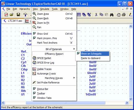
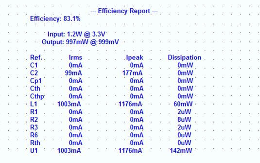
32 Viewing Efficiency Report 32
33 Simulate a Transient Response?


34 Current Load and Pulse Function Your can simulate a load with a Resistor or Current load In particular the Pulse function in a current load is helpful in transient response analysis Steps a current load from one value to another 34

35 Edit the Current Load to a Pulse Function Right click on the current load Select Pulse Modify the Attributes 35
36 More Information and Support


37 Reminder to Periodically Sync Release It is important to sync your release of LTspice once a month to get the latest Software update and bug fix Models Sample circuits and examples 37

38 Built-in Help System Select F1 for help menu 38
39 Paper Manual Download the pdf of the help pages from: 39


40 ing Support Make sure you re using the current version with Field sync. 40
41 LTspice Support Group The group has a Files section with additional tutorials, libraries, and examples Visit the user group Join LTspice Yahoo Group LTspice-subscribe@yahoogroups.com Subject=Subscribe 41
Copyright 2008 Linear Technology. All rights reserved. Getting Started
 Copyright. All rights reserved. Getting Started Copyright. All rights reserved. Draft a Design Using the Schematic Editor 14 Start with a New Schematic New Schematic Left click on the New Schematic symbol
Click on the SwCAD III shortcut created by the software installation.
 LTSpice Guide Click on the SwCAD III shortcut created by the software installation. Select File and New Schematic. Add a component Add a resistor Press R or click the resistor button to insert a resistor.
Manual for Wavenology EM Graphic Circuit Editor. Wave Computation Technologies, Inc. Jan., 2013
 Manual for Wavenology EM Graphic Circuit Editor Wave Computation Technologies, Inc. Jan., 2013 1 Introduction WCT Graphic Circuit Editor is used to build a Spice circuit model in WCT EM full wave simulator.
GETTING STARTED WITH ADS
 ADS Startup Tutorial v2 Page 1 of 17 GETTING STARTED WITH ADS Advanced Design System (ADS) from Agilent Technologies is an extremely powerful design tool for many aspects of electrical and computer engineering
Tutorial 3: Using the Waveform Viewer Introduces the basics of using the waveform viewer. Read Tutorial SIMPLIS Tutorials SIMPLIS provide a range of t
 Tutorials Introductory Tutorials These tutorials are designed to give new users a basic understanding of how to use SIMetrix and SIMetrix/SIMPLIS. Tutorial 1: Getting Started Guides you through getting
Setting up an initial ".tcshrc" file
 ECE445 Fall 2005 Introduction to SaberSketch The SABER simulator is a tool for computer simulation of analog systems, digital systems and mixed signal systems. SaberDesigner consists of the three tools,
LTSPICE MANUAL. For Teaching Module EE4415 ZHENG HAUN QUN. December 2016
 LTSPICE MANUAL For Teaching Module EE4415 ZHENG HAUN QUN December 2016 DEPARTMENT OF ELECTRICAL AND COMPUTER ENGINNERING NATIONAL UNIVERSITY OF SINGAPORE Contents 1. Introduction... 2 1.1 Installation...
EE 210 Lab Assignment #2: Intro to PSPICE
 EE 210 Lab Assignment #2: Intro to PSPICE ITEMS REQUIRED None Non-formal Report due at the ASSIGNMENT beginning of the next lab no conclusion required Answers and results from all of the numbered, bolded
How to Get Started. Figure 3
 Tutorial PSpice How to Get Started To start a simulation, begin by going to the Start button on the Windows toolbar, then select Engineering Tools, then OrCAD Demo. From now on the document menu selection
2008 년안산일대디지털정보통신학과 CAD 강의용자료 PADS 2007
 2008 년안산일대디지털정보통신학과 CAD 강의용자료 PADS 2007 1 Learning the PADS User Interface What you will learn: Modeless Commands Panning & Zooming Object Selection Methods Note: This tutorial will use PADS Layout to
TINA-TI Simulation Software. Application Note
 TINA-TI Simulation Software Application Note Phil Jaworski Design Team 6 11/16/2012 Abstract TINA-TI is a circuit design and simulation tool created by both Texas Instruments and DesignSoft that has helped
One possible window configuration preferences for debug cycles
 NEW USER S TUTORIAL Welcome to ICAP/4, Intusoft s suite of analog and mixed-signal simulation products. There is also a New User s Tutorial 2 as follow-on to this tutorial for non-icap/4rx products. Let
Cadence Tutorial A: Schematic Entry and Functional Simulation Created for the MSU VLSI program by Andrew Mason and the AMSaC lab group.
 Cadence Tutorial A: Schematic Entry and Functional Simulation Created for the MSU VLSI program by Andrew Mason and the AMSaC lab group. Revision Notes: Aug. 2003 update and edit A. Mason add intro/revision/contents
There are three windows that are opened. The screen that you will probably spend the most time in is the SCHEMATIC page.
 Pspice Tutorial Create a new project and select Analog or Mixed A/D. Choose an appropriate project name and a path. A new window pop up with the Pspice project type, select Create a blank project and click
TUTORIAL How to Use the SPICE Module
 TUTORIAL How to Use the SPICE Module February 2018 1 1. Overview The SPICE Module is an add-on option in PSIM. Powered by CoolSPICE developed by CoolCAD Electronics LLC., the SPICE Module provides a SPICE
OrCad & Spice Tutorial By, Ronak Gandhi Syracuse University
 OrCad & Spice Tutorial By, Ronak Gandhi Syracuse University Brief overview: OrCad is a suite of tools from Cadence for the design and layout of circuit design and PCB design. We are currently using version
Simulation examples Chapter overview
 Simulation examples 2 Chapter overview The examples in this chapter provide an introduction to the methods and tools for creating circuit designs, running simulations, and analyzing simulation results.
1. Working with PSpice:
 Applied Electronics, Southwest Texas State University, 1, 13 1. Working with PSpice: PSpice is a circuit simulator. It uses the Kirchhoff s laws and the iv-relation of the used components to calculate
APPENDIX-A INTRODUCTION TO OrCAD PSPICE
 220 APPENDIX-A INTRODUCTION TO OrCAD PSPICE 221 APPENDIX-A INTRODUCTION TO OrCAD PSPICE 1.0 INTRODUCTION Computer aided circuit analysis provides additional information about the circuit performance that
PSpice with Orcad 10
 PSpice with Orcad 10 1. Creating Circuits Using PSpice Tutorial 2. AC Analysis 3. Step Response 4. Dependent Sources 5. Variable Phase VSin Source Page 1 of 29 Creating Circuits using PSpice Start Orcad
MENTOR GRAPHICS IC DESIGN MANUAL. Schematic & Simulation. Gun Jun K Praveen Jayakar Thomas Zheng Huan Qun
 MENTOR GRAPHICS IC DESIGN MANUAL Schematic & Simulation By Gun Jun K Praveen Jayakar Thomas Zheng Huan Qun August 2004 Signal Processing & VLSI Design Laboratory Department of Electrical & Computer Engineering
Lab 1: Analysis of DC and AC circuits using PSPICE
 Lab 1: Analysis of DC and AC circuits using PSPICE 1. Objectives. 1) Familiarize yourself with PSPICE simulation software environment. 2) Obtain confidence in performing DC and AC circuit simulation. 2.
TUTORIAL How to Use the SPICE Module
 TUTORIAL How to Use the SPICE Module November 2017 1 1. Overview The SPICE Module is an add-on option in PSIM. Powered by CoolSPICE developed by CoolCAD Electronics LLC., the SPICE Module provides a SPICE
PSpice Tutorial. Physics 160 Spring 2006
 PSpice Tutorial This is a tutorial designed to guide you through the simulation assignment included in the first homework set. You may either use the program as installed in the lab, or you may install
Revision Notes: July2004 Generate tutorial for single transistor analysis. Based on existing schematic entry tutorial developed for ECE410
 Cadence Analog Tutorial 1: Schematic Entry and Transistor Characterization Created for the MSU VLSI program by Professor A. Mason and the AMSaC lab group. Revision Notes: July2004 Generate tutorial for
Free Microsoft Office 2010 training from MedCerts. Course Outline
 Free Microsoft Office 2010 training from MedCerts Course Outline Microsoft Office Word 2010: Basic Course Introduction Unit 01 - Getting Started Topic A: The Word Window The Word 2010 Window Demo - A-1:
Tutorial : First board in CircuitMaker.
 Tutorial : First board in CircuitMaker. Objectives 1. Create a new project in CircuitMaker. 2. Design electronic circuit in CircuitMaker schematic editor. 3. Design a pcb board for your circuit in CircuitMaker
GreenPoint Design Simulation Tool
 GreenPoint Simulation Tool User s Guide Online and Verification 1 GreenPoint User s Guide Nov-13 What is the GreenPoint Simulation Tool? The GreenPoint Simulation Tool is an interactive online design and
Experiment 1 Electrical Circuits Simulation using Multisim Electronics Workbench: An Introduction
 Experiment 1 Electrical Circuits Simulation using Multisim Electronics Workbench: An Introduction Simulation is a mathematical way of emulating the behavior of a circuit. With simulation, you can determine
TUTORIAL 1. V1.1 Update on Sept 17, 2003 ECE 755. Part 1: Design Architect IC
 TUTORIAL 1 V1.1 Update on Sept 17, 2003 ECE 755 Part 1: Design Architect IC DA-IC provides a design environment comprising tools to create schematics, symbols and run simulations. The schematic editor
Reset Cursor Tool Clicking on the Reset Cursor tool will clear all map and tool selections and allow tooltips to be displayed.
 SMS Featured Icons: Mapping Toolbar This document includes a brief description of some of the most commonly used tools in the SMS Desktop Software map window toolbar as well as shows you the toolbar shortcuts
Introduction to PSpice
 Introduction to PSpice Simulation Software 1 The Origins of SPICE In the 1960 s, simulation software begins CANCER Computer Analysis of Nonlinear Circuits, Excluding Radiation Developed at the University
QUICK START GUIDE FOR DEMONSTRATION CIRCUIT 995A ADJUSTABLE LDO LINEAR REGULATOR LT3080EDD DESCRIPTION
 LT3080EDD DESCRIPTION Demonstration circuit 995A is an adjustable 1.1A linear regulator featuring LT 3080. Architected as a precision current source and voltage follower, it allows this new regulator to
SPICE Models: ROHM Voltage Detector ICs
 SPICE Models: ROHM Voltage Detector ICs BD48 G/FVE,BD49 G/FVE,BD52 G/FVE,BD53 G/FVE, No.10006EAY01 1. INTRODUCTION 1.1 SPICE SPICE is a general-purpose circuit-simulation program for nonlinear DC, nonlinear
EE115C Digital Electronic Circuits. Tutorial 2: Hierarchical Schematic and Simulation
 EE115C Digital Electronic Circuits Tutorial 2: Hierarchical Schematic and Simulation The objectives are to become familiar with Virtuoso schematic editor, learn how to create the symbol view of basic primitives,
Analog IC Simulation. Mentor Graphics 2006
 Analog IC Simulation Mentor Graphics 2006 Santa Clara University Department of Electrical Engineering Date of Last Revision: March 29, 2007 Table of Contents 1. Objective... 3 2. Basic Test Circuit Creation...
- create new schematic to the new project, PCB design begins with a schematic diagram, which present how components are connected
 Eagle 8.x tutorial - create a new project, Eagle designs are organized as projects - create new schematic to the new project, PCB design begins with a schematic diagram, which present how components are
Guide To Making Schematic Components For ExpressSCH
 Guide To Making Schematic Components For ExpressSCH The ExpressSCH program includes hundreds of components and symbols that you can use to draw your schematics. However, sometimes we may not have all of
PREZI QUICK START GUIDE
 PREZI QUICK START GUIDE What is Prezi? On a mission to end boring presentations and make you a great presenter, Prezi is presentation software, which, unlike slides that literally box you in, lets you
EE 330 Spring 2018 Laboratory 2: Basic Boolean Circuits
 EE 330 Spring 2018 Laboratory 2: Basic Boolean Circuits Contents Objective:... 2 Part 1: Introduction... 2 Part 2 Simulation of a CMOS Inverter... 3 Part 2.1 Attaching technology information... 3 Part
DC Circuit Simulation
 Chapter 2 DC Circuit Simulation 2.1 Starting the Project Manager 1. Select Project Manager from the Start All Program Cadence Release 16.5 Project Manager. 2. Select Allegro PCB Designer (Schematic) from
AutoCAD 2009 User InterfaceChapter1:
 AutoCAD 2009 User InterfaceChapter1: Chapter 1 The AutoCAD 2009 interface has been enhanced to make AutoCAD even easier to use, while making as much screen space available as possible. In this chapter,
Size Limitations: Circuits are limited to 50 components and 75 equations (nodes + inductors + sources).
.") Micro-Cap 11 Evaluation Version The Evaluation Version is provided as an introduction to the Micro-Cap 11 program. It is a working version and a highly capable product in its own right. It is provided
Micro-Cap 11 Evaluation Version The Evaluation Version is provided as an introduction to the Micro-Cap 11 program. It is a working version and a highly capable product in its own right. It is provided
Cadence Tutorial A: Schematic Entry and Functional Simulation Created for the MSU VLSI program by Professor A. Mason and the AMSaC lab group.
 Cadence Tutorial A: Schematic Entry and Functional Simulation Created for the MSU VLSI program by Professor A. Mason and the AMSaC lab group. Revision Notes: Jan. 2006 Updated for use with spectre simulator
Editing Multiple Objects. Contents
 Editing Multiple Objects Contents Selecting Multiple Objects Inspecting the Objects Editing the Objects Editing Group Objects Step 1. Selecting the Capacitors Step 2. Changing the Comment String Step 3.
SOUTHERN POLYTECHNIC S. U.
 SOUTHERN POLYTECHNIC S. U. ECET 1012 Laboratory Exercise #4 ELECTRICAL & COMPUTER ENGINEERING TECHNOLOGY Introduction to PSpice Name Lab Section Date Overview: This laboratory experiment introduces the
EXPERIMENT 1 INTRODUCTION TO MEMS Pro v5.1: DESIGNING a PIEZO- RESISTIVE PRESSURE SENSOR
 EXPERIMENT 1 INTRODUCTION TO MEMS Pro v5.1: DESIGNING a PIEZO- RESISTIVE PRESSURE SENSOR 1. OBJECTIVE: 1.1 To learn and get familiar with the MEMS Pro environment and tools 1.2 To learn the basis of process
Part. Summary. Modified by Susan Riege on Aug 5, Parent page: Objects
 Part Old Content - visit altium.com/documentation Modified by Susan Riege on Aug 5, 2016 Parent page: Objects Related Resources Net Ties and How to Use Them (PDF) The Part represents the actual physical
NI Circuit Design Suite
 RELEASE NOTES NI Circuit Design Suite Version 10.0 Contents These release notes contain system requirements for NI Circuit Design Suite 10.0, and information about product tiers, new features, documentation
HW #2 - Eagle Tutorial
 HW #2 - Eagle Tutorial The goal of this homework is to teach the user the basic steps of producing a switching power supply schematic and a printed circuit board using the Eagle Application. While tutorial
Virtuoso Schematic Composer
 is a schematic design tool from Cadence. In this tutorial you will learn how to put electrical components, make wire connections, insert pins and check for connection error. Start Cadence Custom IC Design
Computer Shortcut Keys
 Powered By Computer Shortcut Keys Let s kickstart the list with the most common shortcuts that you ll often use. F1 [Display Help] F2 [Rename the selected item] F3 [Search for a file or folder] F4 [Display
Lesson 1: Getting Started with OrCAD Capture
 1 Lesson 1: Getting Started with OrCAD Capture Lesson Objectives Discuss design flow using OrCAD Capture Learn how to start OrCAD Capture The OrCAD Capture Start Page Open an existing Project Explore the
Getting started. Starting Capture. To start Capture. This chapter describes how to start OrCAD Capture.
 Getting started 1 This chapter describes how to start OrCAD Capture. Starting Capture The OrCAD Release 9 installation process puts Capture in the \PROGRAM FILES\ORCAD\CAPTURE folder, and adds Pspice Student
Orcad Tutorial: Oscillator design and Simulation Schematic Design and Simulation in Orcad Capture CIS Full Version
 Orcad Tutorial: Oscillator design and Simulation Prof. Law Schematic Design and Simulation in Orcad Capture CIS Full Version Notation: To simplify what one should click to perform a task, the following
PDK-Based Analog/Mixed-Signal/RF Design Flow 11/17/05
 PDK-Based Analog/Mixed-Signal/RF Design Flow 11/17/05 Silvaco s What is a PDK? Which people build, use, and support PDKs? How do analog/mixed-signal/rf engineers use a PDK to design ICs? What is an analog/mixed-signal/rf
SILVACO. An Intuitive Front-End to Effective and Efficient Schematic Capture Design INSIDE. Introduction. Concepts of Scholar Schematic Capture
 TCAD Driven CAD A Journal for CAD/CAE Engineers Introduction In our previous publication ("Scholar: An Enhanced Multi-Platform Schematic Capture", Simulation Standard, Vol.10, Number 9, September 1999)
Orcad Capture Quick Reference
 Orcad Capture Quick Reference Shortcut keys The toolbar The schematic page editor tool palette The part editor tool palette Cadence PCB Systems Division (PSD) offices PSD main office (Portland) (503) 671-9500
QUICK START GUIDE FOR DEMONSTRATION CIRCUIT 740 TRACKER/SEQUENCER DEMO BOARD
 DESCRIPTION QUICK START GUIDE FOR DEMONSTRATION CIRCUIT 740 LTC2922 Demonstration circuit 740 is a tracker/sequencer demo board featuring the LTC2922 that monitors up to five external power supplies and
CS755 CAD TOOL TUTORIAL
 CS755 CAD TOOL TUTORIAL CREATING SCHEMATIC IN CADENCE Shi-Ting Zhou shi-ting@cs.wisc.edu After you have figured out what you want to design, and drafted some pictures and diagrams, it s time to input schematics
EE 471: Transport Phenomena in Solid State Devices
 EE 471: Transport Phenomena in Solid State Devices HW7 Due: 4/17/18 For this homework, you will download a free PC version of the industry standard SPICE circuit simulator called LTspice, provided by Linear
CS/EE 5720/6720 Analog IC Design Tutorial for Schematic Design and Analysis using Spectre
 CS/EE 5720/6720 Analog IC Design Tutorial for Schematic Design and Analysis using Spectre Introduction to Cadence EDA: The Cadence toolset is a complete microchip EDA (Electronic Design Automation) system,
FACULTY OF ENGINEERING MULTIMEDIA UNIVERSITY LAB SHEET DIGITAL INTEGRATED CIRCUIT
 FACULTY OF ENGINEERING MULTIMEDIA UNIVERSITY LAB SHEET DIGITAL INTEGRATED CIRCUIT DIC1: Schematic Design Entry, Simulation & Verification DIC2: Schematic Driven Layout Drawing (SDL) Design Rule Check (DRC)
Experiment 4.A. Speed and Position Control. ECEN 2270 Electronics Design Laboratory 1
 .A Speed and Position Control Electronics Design Laboratory 1 Procedures 4.A.0 4.A.1 4.A.2 4.A.3 4.A.4 Turn in your Pre-Lab before doing anything else Speed controller for second wheel Test Arduino Connect
MEMS Pro v5.1 Layout Tutorial Physical Design Mask complexity
 MEMS Pro v5.1 Layout Tutorial 1 Physical Design Mask complexity MEMS masks are complex with curvilinear geometries Verification of manufacturing design rules is important Automatic generation of mask layout
Lesson 17: Building a Hierarchical Design
 Lesson 17: Building a Hierarchical Design Lesson Objectives After you complete this lesson you will be able to: Explore the structure of a hierarchical design Editing the Training Root Schematic Making
SystemVision Example: H-Bridge SPICE Motor Controller
 SystemVision Example: H-Bridge SPICE Motor Controller Copyright Mentor Graphics Corporation 2003 All Rights Reserved. This document contains information that is proprietary to Mentor Graphics Corporation.
TUTORIAL How to Use the SPICE Module
 TUTORIAL How to Use the SPICE Module November 2016 1 1. Overview The SPICE Module is an add on option in PSIM. Powered by CoolSPICE from CoolCAD Electronics LLC., the SPICE Module provides a SPICE simulation
Using KiCad with AimSpice Doc 0.2 CETA - Univ. Hartford, Connecticut, USA
 Using KiCad with AimSpice Doc 0.2 CETA - Univ. Hartford, Connecticut, USA KiCad is a open source software package for schematic capture and PC board layout. KiCad also provides some capability in producing
Lab 5: Circuit Simulation with PSPICE
 Page 1 of 11 Laboratory Goals Introduce text-based PSPICE as a design tool Create transistor circuits using PSPICE Simulate output response for the designed circuits Introduce the Tektronics 571 Curve
EAGLE Schematic Software Cornerstone Electronics Technology and Robotics II
 EAGLE Schematic Software Cornerstone Electronics Technology and Robotics II Administration: o Prayer EAGLE Light Edition: o The name EAGLE is an acronym which stands for Easily Applicable Graphical Layout
Experiment 1 Introduction to PSpice
 Experiment 1 Introduction to PSpice W.T. Yeung and R.T. Howe UC Berkeley EE 105 Fall 2003 1.0 Objective One of the CAD tools you will be using as an circuit designer is SPICE, a Berkeleydeveloped industry-standard
How to use this simulator
 How to use this simulator Introduction Reference Designs Simulation Types Simulation Time Schematic Editing Execute Simulation Thermal Results Result Waveforms Zooming Panning Cursors Moving Store and
Test Procedure for the NIS5101
 1 Test Procedure for the NIS5101 09/06/2004 Board Description: The NIS5101 demo-board has several test points that are used to measure different device functions. The test procedure for each of the tests
UCL Depthmap 7: Convex Space Analysis
 UCL Depthmap 7: Convex Space Analysis Version 7.12.00c Outline This tutorial will cover drawing a convex map, linking the spaces, and then analysing it. New file First, begin a New file, either from the
Guardian NET Layout Netlist Extractor
 Outline What is Guardian NET Key Features Running Extraction Setup Panel Layout Annotation Layout Text Extraction Node Naming Electric Rule Checking (ERC) Layout Hierarchy Definition Hierarchy Checker
Introduction to PowerWorld Simulator: Interface and Common Tools
 Introduction to PowerWorld Simulator: Interface and Common Tools I1: The PowerWorld Simulator Case Editor 2001 South First Street Champaign, Illinois 61820 +1 (217) 384.6330 support@powerworld.com http://www.powerworld.com
Version
 TinyCAD User's Manual Version 2.80.08 http://tinycad.sourceforge.net Copyright 1994-1995,2002-2015 Matt Pyne. This program is free software; you can redistribute it and/or modify it under the terms of
U P C S T U D I O O P E R A T I O N S M A N U A L. Version 1.0 Jan UPC STUDIO OPERATIONS MANUAL Version 1.0 Jan
 U P C S T U D I O O P E R A T I O N S M A N U A L Version 1.0 Jan. 2007 UPC STUDIO OPERATIONS MANUAL Version 1.0 Jan. 2007 1 C O N T E N T S 1.0 Introducing UPC Studio... 1 2.0 System Requirements... 2
Microsoft Word 2010 Basics
 1 Starting Word 2010 with XP Click the Start Button, All Programs, Microsoft Office, Microsoft Word 2010 Starting Word 2010 with 07 Click the Microsoft Office Button with the Windows flag logo Start Button,
KiCad Example Schematic ( ) Wien Bridge Oscillator
 Wien Bridge Oscillator") KiCad Example Schematic (2010-05-05) Wien Bridge Oscillator University of Hartford College of Engineering, Technology, and Architecture The following tutorial in that it walks you through steps to use
KiCad Example Schematic (2010-05-05) Wien Bridge Oscillator University of Hartford College of Engineering, Technology, and Architecture The following tutorial in that it walks you through steps to use
MAXREFDES108#: NON-ISOLATED 12V/1A POE POWERED DEVICE POWER SUPPLY
 System Board 6289 MAXREFDES108#: NON-ISOLATED 12V/1A POE POWERED DEVICE POWER SUPPLY To meet the increasing demands for non-isolated Power over Ethernet (PoE) power solutions, Maxim has developed innovative,
Opening Screen When you first enter Slick!, a blank opening screen will appear as shown below.
 Quick Start This will provide you an overview on how to:?? select and view a file?? zoom in an out of the graphics window?? panning around the graphics window?? zoom to the extents of graphics window??
Instructions for designing the HelloWorld circuit board using Autodesk Eagle 8.6.0
 Instructions for designing the HelloWorld circuit board using Autodesk Eagle 8.6.0 FABLAB BRIGHTON 2018 These instructions take you through step-by-step the process of creating the full circuit board design
Design capture, simulation and layout - an introduction Tutorial
 Design capture, simulation and layout - an introduction Tutorial A step-by-step introduction to Altium s complete board-level design system 1 Software, documentation and related materials: Copyright 2002
Introduction to Electronics Workbench
 Introduction to Electronics Workbench Electronics Workbench (EWB) is a design tool that provides you with all the components and instruments to create board-level designs on your PC. The user interface
Cadence Schematic Tutorial. EEE5320/EEE4306 Fall 2015 University of Florida ECE
 Cadence Schematic Tutorial EEE5320/EEE4306 Fall 2015 University of Florida ECE 1 Remote access You may access the Linux server directly from the NEB Computer Lab using your GatorLink username and password.
EE115C Digital Electronic Circuits. Tutorial 4: Schematic-driven Layout (Virtuoso XL)
") EE115C Digital Electronic Circuits Tutorial 4: Schematic-driven Layout (Virtuoso XL) This tutorial will demonstrate schematic-driven layout on the example of a 2-input NAND gate. Simple Layout (that won
EE115C Digital Electronic Circuits Tutorial 4: Schematic-driven Layout (Virtuoso XL) This tutorial will demonstrate schematic-driven layout on the example of a 2-input NAND gate. Simple Layout (that won
GETTING STARTED. Personal Computer Circuit Design Tools
 Personal Computer Circuit Design Tools GETTING STARTED copyright intusoft 1986-1997 P.O.Box 710 San Pedro, Ca. 90733-0710 Tel. (310) 833-0710 Fax (310) 833-9658 web - www.intusoft.com email - info@intusoft.com
SUE Design Manager Tutorial. Version 4.3. Micro Magic Tools. Juniper Networks, Inc.
 SUE Design Manager Tutorial Micro Magic Tools Version 4.3 Juniper Networks, Inc. 1194 North Mathilda Avenue Sunnyvale, CA 94089 USA 408-745-2000 www.micromagic.com Part Number: SUE4.3, Revision 1 Copyright
Thermal Transient Test Installation and Operating Manual
 Thermal Transient Test Installation and Operating Manual 2705A De La Vina Street Santa Barbara, California 93105 Telephone (805) 682-0900 descon@silcom.com www. santabarbaraautomation.com Installation
Ansys Designer RF Training Lecture 2: Introduction to the Designer GUI
 Ansys Designer RF Solutions for RF/Microwave Component and System Design 7. 0 Release Ansys Designer RF Training Lecture 2: Introduction to the Designer GUI Ansoft Designer Desktop Menu bar Toolbars Schematic
MAXREFDES24EVSYS User Manual
 MAXREFDES24EVSYS User Manual Rev 1; 1/15 ADCLITE2 ANALOG SIGNAL CAPTURE GUI Windows PC REFDES24 4-CHANNEL ANALOG OUTPUT GUI 20 30VDC (>150mA) MAXREFDES24 MAX1659 LDO MAX17498 FLYBACK CONTROL MAX6126 VREF
Getting_started_EN (Ind : 3) 06/01/2014. elecworks. Getting Started
 06/01/2014. elecworks. Getting Started") Getting_started_EN (Ind : 3) 06/01/2014 elecworks Getting Started 1 Start with elecworks This document has been made to help you in starting elecworks. It summarizes the features available. If you would
Getting_started_EN (Ind : 3) 06/01/2014 elecworks Getting Started 1 Start with elecworks This document has been made to help you in starting elecworks. It summarizes the features available. If you would
ELEC451 Integrated Circuit Engineering Using Cadence's Virtuoso Layout Editing Tool
 ELEC451 Integrated Circuit Engineering Using Cadence's Virtuoso Layout Editing Tool Contents Contents 1. General 2. Creating and Working On a Layout o 2.1 Undoing/Re-doing an Action o 2.2 Display Options
TQPED MMIC Design Training
 TQPED MMIC Design Training Outline Installation and Use of the Library AWR AWR Design Kit (PDK Process Design Kit) ICED Layout Kit Create a new document using the Library Environment Setup Hotkeys Background
UNIVERSITY OF NORTH CAROLINA AT CHARLOTTE Department of Electrical and Computer Engineering
 UNIVERSITY OF NORTH CAROLINA AT CHARLOTTE Department of Electrical and Computer Engineering EXPERIMENT 5 ZENER DIODE VOLTAGE REGULATOR, DIODE CLIPPERS AND CLAMPERS OBJECTIVES The purpose of this experiment
Introduction to PCB Design with EAGLE. Jianan Li
 Introduction to PCB Design with EAGLE Jianan Li Install EAGLE Download EAGLE: http://www.cadsoftusa.com/download-eagle/ Choose Run as Freeware during installation Create a New Project Launch EAGLE and
Schematic/Design Creation
 Schematic/Design Creation D A T A S H E E T MAJOR BENEFITS: Xpedition xdx Designer is a complete solution for design creation, definition, and reuse. Overview Creating competitive products is about more
1. Go to the project manager. 2. Select the line Lowpass filter.dsn and right click Part manager. Page 1 of 13
 Component management In you can easily manage components and their related information. Assembly variants and Bill of Materials (BOM) for these can also be defined. The built in Part Manager window makes