PS-IN202 Weighing Indicator User Manual
|
|
|
- Erick Thomas
- 6 years ago
- Views:
Transcription


1 PS-IN202 Weighing Indicator User Manual Version
2 Contents FRONT AND REAR VIEW OF THE INDICATOR CHAPTER 1 CONNECTIONS 1.1 WHAT'S IN THE BOX 1.2 CONNECTING TO THE WEIGH PLATFORM 1.3 CONNECTION TO A PRINTER OR COMPUTER 1.4 CONNECTION TO THE POWER SUPPLY CHAPTER 2 CONFIGURATION 2.1 SET UP ( P ) MENU 2.2 Setup Menu Chart 2.3 Exiting the setup menu 2.4 USER ( S ) MENU 2.5 User Menu Chart 2.6 Setup Menu Descriptions 2.7 User Menu Descriptions CHAPTER 3 CALIBRATION 3.1 Zero Calibration 3.2 Span Calibration 3.3 View calibration values 3.4 Key-in zero calibration value 3.5 Key-in span calibration value CHAPTER 4 OPERATION 4.1 Display 4.2 Display Details 4.3 Keyboard 4.4 Weighing 4.5 Tare Function PS-IN202 Indicator - 1 -


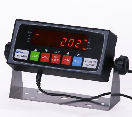
3 Front and Rear View of the Indicator FIG1 and FIG 2 show the front and rear view of the indicator. FIG 1.1 FIG 1.2 FIG 2 PS-IN202 Indicator - 2 -
4 Chapter 1 Connections 1.1 WHAT'S IN THE BOX The box contents are as follows: Indicator Power Adaptor Wall Mount Bracket 4 pin connector This Manual 1.2 CONNECTING TO THE WEIGH PLATFORM a. Plug the 4-pin connector into the signal port on the rear panel of the indicator (for PS- IN202SS you need to mount the bare wires onto the board directly). Wire the bare wires and shield to the weigh platform s load cell(s) or junction box using the color codes shown below: RED: BLACK: GREEN: WHITE: +Excitation -Excitation +Signal -Signal b. Alternatively, instead of using the shielded load cell cable supplied, a cable may be assembled with the pin assignments shown in FIG 3: FIG CONNECTION TO A PRINTER OR COMPUTER The indicator contains a standard full duplex RS-232 serial port, designed for connection to either a PC or a serial printer as shown in FIG 4. FIG 4 The indicator can be directly interfaced to a serial printer, remote display or computer communication cable (not included) using the D-SUB9 serial port connector. This indicator is compatible with Prime Interface Software. PS-IN202 Indicator - 3 -
5 Pin No. Pin Name 1.4 CONNECTION TO THE POWER SUPPLY The indicator comes with an external AC adapter. Connect the AC adapter to the indicator then plug the main plug into a standard wall outlet. When plugged in, the built-in battery is being recharged. The recharge light will be on. We strongly recommend recharging the indicator for at least 12 hours before the first-time use. PS-IN202 Indicator - 4 -
6 Chapter 2 Configuration The indicator contains two main setup menus: The Setup ( P ) menu This configures the indicator to the weigh platform The User ( S ) menu This configures the serial communication port and enables some user options. The Setup and User menus consist of several menu selections, each with its own sub-menu. To set up the indicator, first select the appropriate menu mode. Keys [UNIT], [ZERO], [TARE] and [PRINT] become direction navigators (as indicated by the arrows above them) to move around the menus and the [NET/GROSS] key is used to save or SET the selections. 2.1 SET UP ( P ) MENU a. Switch off the indicator. b. On the rear panel, move the Calibration/Setup Switch to the Setup position. Left is calibration mode, right is weighing mode. c. Switch on the indicator. The indicator will display P 1 to indicate that it is in Setup P menu mode. Use the direction keys to navigate around in the Setup Menu Chart. a. To move to a new P heading, use the [TARE] (down) or [PRINT] (up) key to navigate the Setup Menu Chart. b. To move to the selection level, press the [ZERO] (right) key once. The current saved selection is shown. c. To view the available selections for the current P heading, use the [TARE] (left) or [PRINT] (up) key to navigate through the selection field. d. To save a new selection, press the [NET/GROSS] (Set) key.to exit without saving, press the [UNITS] (left) key to return to the current P heading. e. Repeat Steps 1 through 4 until the Setup Menu is programmed. PS-IN202 Indicator - 5 -
7 FIG Setup Menu Chart FIG 6 The User ( S ) sub-menus appear when scrolling left or right from the P menu. Some selections shown are not available on some versions. 2.3 Exiting the setup menu a. Switch off the indicator. b. On the rear panel, move the Calibration/Setup Switch to the Calibration position. Left is calibration mode, right is weighing mode. c. Switch on the indicator. The display will go through a digit check then go into Normal Operating mode. All front panel keys will now return to their normal mode of operation. 2.4 USER ( S ) MENU a. Enter the Setup ( P ) menu. b. Use the right or left direction keys to navigate the Setup ( P ) menu until the indicator shows S 1. Use the direction keys to navigate the User Menu Chart. PS-IN202 Indicator - 6 -
8 c. To move to a new S heading, use the [TARE] (down) or [PRINT] (up) key to navigate the User Menu Chart. d. To move to the selection level, press the [ZERO] (right) key once. The current saved selection is shown. e. To view the available selections for the current S heading, use the [TARE] (down) or [PRINT] (up) key to navigate the selection field. f. To save a new selection, press the [NET/GROSS] (Set) key.to exit without saving, press the [UNITS] (left) key to return to the current S heading. g. Repeat Steps 2 through 5 until the Communication Menu is programmed. FIG User Menu Chart FIG Setup Menu Descriptions This section provides a more detailed description of the selections found in the Setup Menu Chart. Factory-set defaults are shown in bold with a checkmark ( ). PS-IN202 Indicator - 7 -
9 NAME/CODE DESCRIPTION CODE/VALUE P1 Full capacity of the scale. Value should be consistent with legal Capacity requirements and environmental limits on the useful system resolution. P2 Accuracy P3 Span P4 Zero Track Band P5 Zero Range P6 Power on Zero Range P7 Motion Band P8 Digital Filter P9 Overload Limit P10 Calibration Unit P11 Zero Calibration P12 Span Calibration P13 View Calibration P14 Key-in Zero P15 Factory Reset P16 Normal/Slave Mode Setting Accuracy of the scale. Value should be consistent with legal requirements and environmental limits on the useful system resolution. Span Gain is related to the A/D integration time. The larger the span, the higher the internal resolution, but the slower the update speed. Note that the scale must be recalibrated whenever this parameter is altered. See Appendix C for more information. Selects the range within which the scale will automatically zero. Note that the scale must be in standstill to automatically zero. Selections are in Display Divisions. Selects the range within which the scale may be zeroed. Note that the indicator must be in standstill to zero the scale. Set the zeroing range after the indicator powers on. 0 means deactivate Power On Zeroing Sets the level at which motion is detected by comparing the present display update with the previous one. If motion is not detected for two seconds or more, the scale is in standstill and can process a Print or Zero command. Maximum value varies depending on the local regulations. Averages weight readings to produce higher stability. The higher the filter setting the greater the stability but the slower the indicator s response time. Choose Med unless a very fast response is needed Selects the desired formula which determines the point at which the indicator shows overload. All selections are based on the primary unit selected in P8 FS = Full Scale in primary units Selects the primary base unit to be used in the calibration process. Also the default unit for normal operation. 1 = calibration unit is lb 2 = calibration unit is kg Places the indicator into the zero calibration routine. Scrolling down with the [ZERO] key one level begins the procedure Places the indicator into the span calibration routine. Scrolling down with the [ZERO] key one level begins the procedure Actuates the function that allows the user to view both the zero and span calibration value. The values displayed in this function are valid only after calibration (P11 and P12) have been successfully completed. Scrolling down with the [ZERO] key one level begins the procedure Allows the user to key in a known zero calibration value in case of memory loss in the field. Scrolling down with the [ZERO] key one level begins the procedure This sub menu will reset all parameters in the P and S menu to the default setting. USE WITH CAUTION! Set the indicator to be normal or slave mode. n means normal; s means slave. Connect the indicator through RS232 with another indicator to be used an additional display for slave mode. Dynamic d 0.5d 1d, 3d, 5d 100% 1.9%, 2%, 20% 0, 2%, 3%, 20% 100% 1d 3d, 5d 10d FAST MED SLOW FS FS+ 2% FS + 1d FS + 9d 1 2 Press [ZERO] key to begin sequence Press [ZERO] key to begin sequence Press [ZERO] key to begin sequence Press [ZERO] key to begin sequence Press [ZERO] key twice to begin sequence N S PS-IN202 Indicator - 8 -
10 P17 Counting Mode setting P18 Animal Mode P19 Accumulation (SS Only) Activate / deactivate the counting mode. 1 is ON, 0 is OFF 0 1 Set the divisions for animal weighing hold function Set accumulation modes: Automatic or Manual In Automatic mode, it saves weights automatically when it is stable. XXd Auto Man 2.7 Communication Menu Descriptions This section provides a more detailed description of the selections found in the User Menu Chart. Factory-set defaults are shown in bold with a checkmark ( ). NAME/CODE DESCRIPTION CODE/VALUE S1 Baud Rate Selects the baud rate for data transmission through the serial port S2 Data Bits and Parity S3 Mode of Serial Transmission S4 Display Check S5 Disable the lb/kg Key S6 Serial Port Mode S7 ID No. Enable S8 ID No. Entry S9 No of Line Feeds S10 Handshaking Enable Selects the number of data bits and parity of serial transmission. "8n" = 8 data bits with no parity bit and one stop bit "7O" = 7 data bits with odd parity bit and one stop bit "7E" = 7 data bits with even parity bit and one stop bit "7n" = 7 data bits with no parity bit and two stop bits Selects when data will be sent out of the serial port to a printer or computer: C = Continuous Mode; Send Data continuously d = demand mode; send data when a PRINT command is issued from the printer, computer or indicator Actuates the function that illuminates all digit segments, decimal points, LCD enunciators in a test sequence. Pressing the [ZERO] key to scroll down one level begins the test sequence Allows the lb/kg to be disabled so that an operator cannot accidentally press the key and change the displayed units. 0 = Disable the lb/kg key 1 = Enable the lb/kg key Selects the mode of the RS-232 serial port: Refer to Appendix B for more information 0 = Full Duplex Mode 1 = Print Ticket Mode Allows the ID number to be disabled in the Print Ticket Mode. Valid only when S6 is set to 1 0 = Disable the ID No. 1 = Enable the ID No. Actuates the function that allows entry of a new ID No. Valid only when S6 is set to 1. Pressing the [ZERO] key to scroll down one level begins the sequence. Actuates the function that allows entry of the desired number of line feeds to be printed in Print Ticket Mode. Valid only when S6 is set to 1. Pressing the [ZERO] key to scroll down one level begins the sequence. Enables hardware handshaking for Print Ticket Mode. Valid only when S6 is set to 1. 0 = Disable Handshaking 1 = Enable Handshaking n 7O 7E 7n C d Press [ZERO] key to begin sequence PS-IN202 Indicator - 9 -
11 S11 Print Header S12 Back light set S13 Time Setting Tells the printer to print the header information. Valid only when S6 is set to 1. 0 = Do NOT Print Header 1 = Print Header Set back light mode: OFF, ON and Auto (when the display is idle, the back light will turn off automatically.) Activate or deactivate the clock when the indicator is in the sleep mode (or idle) ON is activate, OFF is deactivate. Then press Zero key to enter the Date / Time setting. First set the Month/ Date/Year. Press up and down button to change the blinking numbers. Press Zero button to move forward. After the date is done, press Zero button to move to Time setting. When all done, press Zero button to save the changes. 0 1 OFF ON AUTO ON OFF PS-IN202 Indicator
12 Chapter 3 Calibration The indicator is calibrated by following the procedures embedded in P11 (Zero) and P12 (Span) of the Setup Menu. Each procedure enters a value into the indicator's non-volatile memory: P11 is the zero value (deadweight) P12 is the span value (test weight). The minimum test weight that can be used is 1% of the full-scale capacity. After the two calibration procedures are executed successfully, a record should be made of both calibration values in the Calibration Table below using the P 18 View procedure. NOTE: This chapter assumes that the indicator is in Setup ( P ) Menu mode. Calibration Table Indicator Zero Calibration Span Calibration Serial Number 3.1 Zero Calibration a. While in the Setup mode, scroll to "P 11", then scroll down once using the [ZERO] key to enter the zero calibration menu. The display will momentarily show "C 0" followed by a value. This value is the internal A/D count and is useful when trying to troubleshoot setup problems. b. Ensure there are no test weights on the platform and press the [ZERO] key again to zero out the displayed value. c. Press the [NET/GROSS] key to save the zero point value. The display will show "End C0" momentarily then revert back to P11. Proceed to the P12 span calibration to complete the indicator calibration. 3.2 Span Calibration a. While in the Setup mode, scroll to "P 12", then scroll down once using the [ZERO] key to enter span calibration menu. b. The display will momentarily show "C 1" for the span calibration, followed by a value with one flashing digit. This value will be zero with the Decimal Point parameter as selected in P10. Place the test weight on the weighing mechanism. c. Use the four direction keys to adjust the displayed value to the actual test weight value. Increment the flashing digit by pressing the [UNITS] key. Decrement the flashing digit by pressing the [ZERO] key. Pressing the [PRINT] key or the [TARE] key will change the position of the flashing digit. d. After setting the exact value, press the [NET/GROSS] key to save the value. PS-IN202 Indicator
13 e. If the calibration was successful, the display will show "EndC1" momentarily, then go to C2. f. Repeat Steps b-e using different test weights then proceed to Step C3. g. Repeat Steps b-e using different test weights. Proceed to P12. h. If the calibration was not successful, one of the error messages below will appear. Take the indicated action to correct the problem then perform a new calibration. "Err0" - The calibration test weight or the adjusted keyed-in weight is larger than the full capacity of the scale. Change the calibration test weight or check the input data. "Err1" - The calibration test weight or the adjusted keyed-in weight is smaller than 1% of the full capacity of the scale. Change the calibration test weight or check the input data. "Err2" - The internal resolution of the scale is not high enough to accept the calibration value. 3.3 View calibration values Note: The values displayed in this procedure are valid only after a successful calibration has been performed using P11 and P12. a. While in the Setup mode, scroll to "F 18", then scroll down once using the [ZERO] key to enter view calibration menu. b. The display will momentarily show "CAL 0" followed by a value. This value is the zero calibration value and should be recorded in the table below. Press any key to continue. c. The display will momentarily show "CAL 1" followed by another value. This value is the span calibration value and should also be recorded in the table below. Press any key to return to upper level (P13). 3.4 Key-in zero calibration value Note: This procedure is intended for emergency use only in the case of non-volatile memory loss. A valid zero calibration value, obtained from a successful P11 calibration procedure, must be used. a. While in the Setup mode, scroll to "P14" then scroll down once using the [ZERO] key. b. The display will momentarily show "CAL 0", followed by a flashing zero. Use the four direction keys (shown in FIG 1) to adjust the displayed value to the zero calibration value. c. After setting the exact value, press the [NET/GROSS] key to save the value. d. The display will show "E CAL 0" momentarily then revert back to P Key-in span calibration value Note: This procedure is intended for emergency use only in the case of non-volatile memory loss. A valid span calibration value, obtained from a successful P12 calibration procedure, must be used. a. While in the Setup mode, scroll to "P15", then scroll down once using the [ZERO] key. PS-IN202 Indicator
14 b. The display will momentarily show "CAL 1", followed by a flashing zero. Use the four direction keys (shown in FIG 1) to adjust the displayed value to the span calibration value. c. After setting the exact value, press the [NET/GROSS] key to save the value. d. If the entered value is greater than zero, the display will show "E CAL 1" momentarily then revert back to P20. If a value of zero is entered, the indicator will briefly show "Err 5" then revert back to the screen described above in Step b. PS-IN202 Indicator

15 Chapter 4 Operation 4.1 Display FIG Display Details LCD Enunciator LED Enunciator ZERO Meaning Centre Zero enunciator. This light is illuminated whenever the displayed weight is within ±0.25 divisions of true zero N NET The indicator is displaying the net weight G GROSS The indicator is displaying the gross weight T TARE The tare weight has been established in the system lb/kg lb, kg, PCS Indicates the unit of the displayed weight. PCS = pieces STABLE This light is illuminated whenever the scale is stable 4.3 Keyboard FIG 10 [UNITS] [ZERO] Toggles the indicator between the available weight units if enabled in the User ( S ) menu. Available weight units are lb and kg. Sets the indicator to display zero provided the following conditions are met: a. The indicator is displaying Gross weight. Version
16 b. The displayed weight is within the zero reset range that is programmed in P4 of the Setup ( P ) Menu. c. The scale is not in motion or in overload. [NET/GROSS] Toggles the indicator between Gross weight and Net weight only if a Tare has been established. [TARE] [PRINT] Used to establish a Tare provided the following conditions are met: a. The indicator is not at or below Gross zero. b. The scale is not in motion or overload. Used to send weight information out to the serial port provided the scale is not in motion or overload. 4.4 Weighing a. Select the desired weighing unit by pressing the [UNITS] key until the desired unit is indicated on the display. b. If necessary, press the [ZERO] key to obtain a weight reading of zero. c. Place the object to be weighed on the scale s platter and allow the weight indication to stabilize. If the item weight exceeds the scale s weight capacity, it displays. d. Read the weight shown on the display. 4.5 Tare Function To weigh an item in a container, the weight of that container must first be subtracted from the overall weight to obtain an accurate weight reading. This is known as taring. a. Select the desired weighing unit by pressing the [UNITS] key until the desired unit is indicated on the display. b. If necessary, press the [ZERO] key to obtain a weight reading of zero. c. Place the empty container on the scale s platter and allow the weight indication to stabilize. d. Press the [TARE] key. The display shows zero weight and turns the NET indication on. e. Place the material to be weighed in the container and allow the weight indication to stabilize. f. Read the weight shown on the display. e. The display can be toggled between gross weight and net weight by pressing the [NET/GROSS] key. PS-IN202 Indicator
COMPLETE MANUAL. WEIGHING INDICATOR TI-1200 and TI-1200-S TI-1200 with rechargeable battery.
 COMPLETE MANUAL WEIGHING INDICATOR TI-1200 and TI-1200-S TI-1200 with rechargeable battery. TI-1200-S without rechargeable battery and with a smaller cabinet. Note: When TI-1200 is shipped as a part of
Digital Weight Indicator Setup / Operation Manual
 Digital Weight Indicator Setup / Operation Manual Load Cell Central follows a policy of continuous improvement and reserves the right to change specifications without notice. 2013 Load Cell Central Toll
TI-1600 Series. Digital Indicator. Setup / Operation Manual. Revision 1.5 June 5, 2006
 TI-1600 Series Digital Indicator Setup / Operation Manual Revision 1.5 June 5, 2006 2001 Triner Scale & Mfg. Co., Inc Contents subject to change without notice. Triner Scale & Mfg. Co., Inc 8411 Hacks
DCS Series. Digital Counting Scale. Setup Manual
 DCS Series Digital Counting Scale Setup Manual Revision 1.1 February 12, 1997 1996-1997 Transcell Technology, Inc. Contents subject to change without notice. Transcell Technology, Inc. 975 Deerfield Parkway
Digital Bench Scale. Revision 1.2 September 14, 2000 Contents subject to change without notice.
 Digital Bench Scale Revision 1.2 September 14, 2000 Contents subject to change without notice. Salter Brecknell Weighing Products 1000 Armstrong Drive Fairmont, MN 56031 Tel (800) 637-0529 Tel (507) 238-8702
Model S200 Series. Revision 1.0 July, Contents subject to change without notice.
 Model S200 Series Revision 1.0 July, 2003 Contents subject to change without notice. Salter Brecknell Weighing Products 1000 Armstrong Drive Fairmont, MN 56031 Tel (800) 637-0529 Tel (507) 238-8702 Fax
Digital Indicator. Revision 1.6 March 15, Transcell Technology, Inc. Contents subject to change without notice.
 TI-1500 Series Digital Indicator Setup / Operation Manual Revision 1.6 March 15, 2005 1999-2005 Transcell Technology, Inc. Contents subject to change without notice. Transcell Technology, Inc. 975 Deerfield
TI-500 Plus DIGITAL WEIGHT INDICATOR Setup / Operation Manual
 TI-500 Plus DIGITAL WEIGHT INDICATOR Setup / Operation Manual Revision 1.0 975 Deerfield Parkway Buffalo Grove, IL 60089 April 3, 2008 Tel (847) 419-9180 Fax (847) 419-1515 http://www.transcell.net i TABLE
Digital Bench Scale. Revision 8.93 August 12, 1993
 Digital Bench Scale Revision 8.93 August 12, 1993 Salter Brecknell Weighing Products 1000 Armstrong Drive Fairmont, MN 56031 Tel (800) 637-0529 Tel (507) 238-8702 Fax (507) 238-8271 E-mail: sales@salterbrecknell.com
PC 150. Digital Bench Scale. Operation Manual
 PC 150 Digital Bench Scale Operation Manual Revision 1.2 September 14, 2000 1996-2000 Transcell Technology, Inc. Contents subject to change without notice. Transcell Technology, Inc. 35 Waltz Drive Wheeling,
Crane Scale. Revision 1.4 February 18, Transcell Technology, Inc. Contents subject to change without notice.
 CR-500 Crane Scale Setup / Operation Manual Revision 1.4 February 18, 2003 2003 Transcell Technology, Inc. Contents subject to change without notice. Transcell Technology, Inc. 975 Deerfield Parkway Buffalo
Digital Bench Scale. Revision 1.2 August 24, Contents subject to change without notice.
 Digital Bench Scale Revision 1. August 4, 000 Contents subject to change without notice. Salter Brecknell Weighing Products 1000 Armstrong Drive Fairmont, MN 56031 Tel (800) 637-059 Tel (507) 38-870 Fax
MODEL TI-700. Digital Weight Indicator (with wireless weighing capability) Installer s Manual
 Installer s Manual") MODEL TI-700 Digital Weight Indicator (with wireless weighing capability) Installer s Manual Revision 3.0 July 31, 2017 Transcell Technology, Inc. 2016-2017. All rights reserved. The information contained
MODEL TI-700 Digital Weight Indicator (with wireless weighing capability) Installer s Manual Revision 3.0 July 31, 2017 Transcell Technology, Inc. 2016-2017. All rights reserved. The information contained
MODEL. TI-500 RF Series. Installer s Manual. Digital Weight Indicator (with wireless weighing capability)
") MODEL TI-500 RF Series Digital Weight Indicator (with wireless weighing capability) Installer s Manual Revision 1.6 April 16, 2018 Transcell Technology, Inc. 2010-2018. All rights reserved. The information
MODEL TI-500 RF Series Digital Weight Indicator (with wireless weighing capability) Installer s Manual Revision 1.6 April 16, 2018 Transcell Technology, Inc. 2010-2018. All rights reserved. The information
BB 8100 SS Operator s Manual & Troubleshooting Guide
 FCC NOTICE BB 8100 SS Operator s Manual & Troubleshooting Guide This equipment has been tested and found to comply with the limits for a Class A digital device, pursuant to Subpart J of Part 15 of the
MODEL TI-500 SL. User Manual. Digital Weight Indicator
 MODEL TI-500 SL Digital Weight Indicator User Manual Revision 1.3 September 12, 2013 i TABLE OF CONTENTS Page Contents INTRODUCTION... 1 FCC NOTE... 1 INSTALLATION... 2 PREPARATION... 2 CONNECTIONS...
PC-150. DIGITAL BENCH SCALE Setup / Operation Manual
 PC-150 DIGITAL BENCH SCALE Setup / Operation Manual Revision 1.3 975 Deerfield Parkway Buffalo Grove, IL 60089 October 6, 2010 Tel (847) 419-9180 Fax (847) 419-1515 http://www.transcell.com 1 ATTENTION:
Digital Weight Indicator Setup / Operation Manual
 Digital Weight Indicator Setup / Operation Manual Revision 1.71 February 25, 2009 TABLE OF CONTENTS Page INTRODUCTION... 1 FCC NOTE... 1 INSTALLATION... 2 PREPARATION... 2 CONNECTIONS... 2 CONNECTING THE
600-E Series. Digital Baggage Scales. Installation / Setup / Operation Manual. Revision 2.3 June 5, Triner Scale & Mfg. Co., Inc.
 600-E Series Digital Baggage Scales Installation / Setup / Operation Manual Revision 2.3 June 5, 2006 2003 Triner Scale & Mfg. Co., Inc. Contents subject to change without notice. Triner Scale 8411 Hacks
CHECK WEIGHING SCALE. Operation Manual. Revision 2.7 June Transcell Technology, Inc. Contents subject to change without notice.
 NEPTUNE-5500 Series CHECK WEIGHING SCALE Operation Manual Revision 2.7 June 29.2004 2003 Transcell Technology, Inc. Contents subject to change without notice. Transcell Technology, Inc. 975 Deerfield Parkway
Digital Counting Scale. Revision 2.4 October 20, Transcell Technology, Inc. Contents subject to change without notice.
 TC-2001 Series Digital Counting Scale Setup & Operation Manual Revision 2.4 October 20, 2003 2001-2003 Transcell Technology, Inc. Contents subject to change without notice. Transcell Technology, Inc. 975
TI DIGITAL WEIGHT INDICATOR Setup / Operation Manual
 TI-1680 DIGITAL WEIGHT INDICATOR Setup / Operation Manual Revision 1.31 975 Deerfield Parkway Buffalo Grove, IL 60089 March 22, 2013 Tel (847) 419-9180 Fax (847) 419-1515 http://www.transcell.com i TABLE
IQ6200/6500 Counting Scales. Installation Manual
 IQ6200/6500 Counting Scales Installation Manual 32224 Contents About this Manual... 1 1.0 Introduction... 1 1.1 Scale Resolution... 2 1.2 Choosing the Best Sample... 2 2.0 Installation and Start-Up...
DIGITAL WEIGHT INDICATOR Setup / Operation Manual
 DIGITAL WEIGHT INDICATOR Setup / Operation Manual Revision 1.1 975 Deerfield Parkway Buffalo Grove, IL 60089 September 20, 2010 Tel (847) 419-9180 Fax (847) 419-1515 http://www.transcell.com i TABLE OF
Copyright Western Scale Co. Limited. All rights reserved.
 MAX DIGITAL WEIGHT INDICATOR OPERATION MANUAL SOFTWARE RELEASE 5.03, 04/2011 Copyright 2007-2011 Western Scale Co. Limited. All rights reserved. Published by: Western Scale Co. Limited. Information in
Revision 1.0 July, Contents subject to change without notice.
 Revision 1.0 July, 2003 Contents subject to change without notice. Salter Brecknell Weighing Products. 1000 Armstrong Drive Fairmont, MN 56031 Tel (800) 637-0529 Tel (507) 238-8702 Fax (507) 238-8271 E-mail:
D-500s Indicator D LED. User Instructions. English Issue September SangR. Page 2. User s manual of Sang D-500s LED
 D-500s Indicator D - 500 LED User Instructions English 8921-004210 Issue September 2010 1 2-2 0 1 0 D 6 0 0 4 6 7 5 Page 2 D-500s Indicator Page 2 Table of Content Section 1: Introduction. 1.1 Introduction
uline.com OVERVIEW OF CONTROLS. k g. Tare Menu. Exit. Print. Units PRINT
 3000SERIES 0 CO On/Zero Off Yes Print Units No PCS NET TARE Function Mode Back Tare Menu Exit k g π H-2587, H-4594 OHAUS DEFENDER 3000 DIGITAL SCALE 1-800-295-5510 uline.com OVERVIEW OF CONTROLS CONTROL
Table of Contents. 3-1 Specifications & Features Front Panel Display Keyboard. 3-3 Rear Panel. 3-4 Power Supply. 4.
 Table of Contents 1. Introduction 1 2. Precaution... 1 3. Product Introduction 3-1 Specifications & Features... 3-2 Front Panel 3-2-1 Display 3-2-2 Keyboard. 3-3 Rear Panel. 3-4 Power Supply. 4. Installation
Model 815 User s Manual
 Model 815 User s Manual CAUTION Risk of electrical shock. Do not remove cover. No user serviceable parts inside. Refer servicing to qualified service personnel. Weigh-Tronix reserves the right to change
Calibration & Connectivity
 Calibration & Connectivity TS-700 Series Digital Indicators This document supplements the User s Guide TS-700 MS TS-700 SS TS-700 WB Full Function/Advanced Function Digital Indicator www.trinerscale.com
WUNDER SA.BI.SRL EN USER MANUAL. MULTIFUNCTIONS ELECTRONIC SCALE MOD. W100 LED. User Manual
 www.wunder.it MULTIFUNCTIONS ELECTRONIC SCALE MOD. W100 LED User Manual Read this manual carefully before using the instrument W100 SCALE W100 INDICATOR INDICE 2. BEFORE USING PAG. 2 3. SPECIFICATIONS
Model 500 Digital Weight Indicator
 Rev. 1.10 Serial Number: Model 500 Digital Weight Indicator USER MANUAL 1992-2000, Reliable Scale Corporation Reliable Scale Corporation 520 Moraine Road NE Calgary, Alberta, Canada Tel:1-800-419-1189
QuickSilver Series Bench Scale
 Operating Manual QuickSilver Series Bench Scale 2004 by Fairbanks Scales Inc. All rights reserved 50738 Issue #1 1/04 Amendment Record QuickSilver Series Bench Scale 50738 Manufactured by Fairbanks Scales
LTS DR2100A/AN Indicator WARRANTY POLICY
 TABLE OF CONTENTS WARRANTY POLICY... 1 CONTACT INFORMATION... 2 GENERAL INFORMATION... 2 STANDARD FEATURES... 3 INDICATOR OPTIONS... 3 DISPLAY DESCRIPTION... 4 DR2100 KEYBOARD LAYOUT... 4 KEYBOARD CONTROLS...
!!!!!!!!!!!!!!!!!!!!!!!!!!!!!!!!!!!!!!!!
 "#$%&"'()*#%&+,"-)&./&+ SECTP-E0403 Contents SECTION 1 INTRODUCTION...... 1 1. 1 Figures...1 1. 2 Specifications.... 1 1. 3 Dimension..1 SECTION 2 KEYBOARD DESCRIPTIONS...2 SECTION 3 OPERATION.....3 3.
SCS3MT080, SCS3MT100, SCS3MT120, SHDHS1500 & SPLS1000 User Manual
 www.scintex.com.au sales@scintex.com.au SCS3MT080, SCS3MT100, SCS3MT120, SHDHS1500 & SPLS1000 User Manual Technical Data Working Temperature:-5 to 35 C Storage Temperature:-25 to 50 C Stainless Steel Casing:
Pennsylvania Scale Company Model 400B Battery Powered Digital Indicator Operation & Calibration Manual
 Pennsylvania Scale Company Model 400B Battery Powered Digital Indicator Operation & Calibration Manual Pennsylvania Scale Company 1042 New Holland Avenue Lancaster PA 17601 For online interactive tech
Weighing Indicator USER S GUIDE. globalindustrial.com. globalindustrial.com. 11 Harbor Park Drive Port Washington, NY 11050
 Weighing Indicator USER S GUIDE 0713 11 Harbor Park Drive Port Washington, NY 11050 Table of Contents I Main Specifications.............................3 II Display and Keyboard..........................4
EB300 Weighing Scale Operation Manual
 EB300 Weighing Scale Operation Manual EB300 User Manual Page 1 of 18 TABLE OF CONTENTS 1. Safety Warnings... 3 2. Features..... 3 3. Options.......... 4 4. Product packaging.. 4 5. Display and keyboard.....
Addendum to TI-500E Plus Setup/Operation Manual For Time, Date, Print Formats Option
 OVERVIEW OF CHANGES 1. This indicator option provides time, date and programmable print formats. Changes to user (A) menu descriptions 1. For A3, selections are designed at d, C and Auto instead of 0,
GS100P. Weighing Controller. Contents. Order Codes
 GS100P Weighing Controller 1 This intelligent weighing controller comes precalibrated to suit either a 4-wire or a 6-wire strain gauge input, and has a number of advanced functions designed specifically
CALIBRATION HI 2151/30 TRADITIONAL HARD CALIBRATION. Mode kg. Cal
 CALIBRATION HI 2151/30 TRADITIONAL HARD CALIBRATION Motion Net ZERO Trk CTR Zero Gross lb Mode kg Tare Print ZERO Test/Clr 0.00 Enter Exit Cal The configuration menu information is entered two ways. o
GT 400 Operators Manual
 GT 400 Operators Manual Ft. Atkinson, Wisconsin USA Panningen, The Netherlands www.digi-star.com D3831-US REV A February 27, 2009 TABLE OF CONTENTS GT400 TABLE OF CONTENTS... 2 CHARGING BATTERY OR WELDING...
GMC-206/215/230 Digital Desktop Weighing Scale Operation Manual
 GMC-206/215/230 Digital Desktop Weighing Scale Operation Manual Version 2.1 Gamma Scale Tel: (905) 455-8333 Fax: (905) 455-0658 E-mail: info@gammascale.com Website: www.gammascale.com 1. Technical Parameters
DWP-98 Series. Counting scale. User s Guide PLEASE READ THIS MANUAL VERY CAREFULLY BEFORE ATTEMPT TO OPERATE THE INSTRUMENT
 c DWP-98 Series Counting scale User s Guide PLEASE READ THIS MANUAL VERY CAREFULLY BEFORE ATTEMPT TO OPERATE THE INSTRUMENT Specifications subject to change without prior notice CONTENTS 1. INSTALLATION
WARRANTY POLICY. 1 CONTACT INFORMATION. 2 GENERAL INFORMATION. 2 STANDARD FEATURES. 3 INDICATOR OPTIONS. 3 DISPLAY DESCRIPTION. 4 KEYBOARD CONTROLS.
 TABLE OF CONTENTS WARRANTY POLICY... 1 CONTACT INFORMATION... 2 GENERAL INFORMATION... 2 STANDARD FEATURES... 3 INDICATOR OPTIONS... 3 DISPLAY DESCRIPTION... 4 DR2100 KEYBOARD LAYOUT... 4 KEYBOARD CONTROLS...
KW serial. User s guide. Bench Scales UGKW-E0302
 KW serial Bench Scales User s guide UGKW-E0302 KW serial bench scale user s manual Table of Contents SECTION 1 INTRODUCTION 1 SECTION 2 SPECIFICATIONS.. 2 SECTION 3 INSTALLATION.3 SECTION 4 KEY DESCRIPTIONS
805HP. Handheld Digital Weight Indicator Operations Manual (V1612) Anyload Transducer Co. Ltd Website:
 Anyload Transducer Co. Ltd Website:") 805HP Handheld Digital Weight Indicator Operations Manual (V1612) Anyload Transducer Co. Ltd Website: www.anyload.com Email: info@anyload.com TABLE OF CONTENTS 1. Introduction and Product Features 3 2.
805HP Handheld Digital Weight Indicator Operations Manual (V1612) Anyload Transducer Co. Ltd Website: www.anyload.com Email: info@anyload.com TABLE OF CONTENTS 1. Introduction and Product Features 3 2.
Optima OP-902 User Manual
 Optima OP-902 User Manual Warnings For safety operation of the weighing indicator, please follow the following warning/ safety instructions: Calibration inspection and maintenance of the indicator are
DWP-PC SERIES PRICE COMPUTING SCALE User s Guide
 DWP-PC SERIES PRICE COMPUTING SCALE User s Guide PLEASE READ THIS MANUAL VERY CAREFULLY BEFORE ATTEMPT TO OPERATE THE INSTRUMENT Specifications subject to change without prior notice CONTENTS 1. INSTALLATION
Optima OP-900-LD Score Board Indicator (with Remote Control) User Manual
 User Manual") Score Board Indicator (with Remote Control) User Manual Warnings For safety operation of the weighing indicator, please follow the following warning/ safety instructions: Calibration inspection and maintenance
Score Board Indicator (with Remote Control) User Manual Warnings For safety operation of the weighing indicator, please follow the following warning/ safety instructions: Calibration inspection and maintenance
805HP. Handheld Digital Weight Indicator Operations Manual (V1612) Anyload Transducer Co. Ltd Website:
 Anyload Transducer Co. Ltd Website:") 805HP Handheld Digital Weight Indicator Operations Manual (V1612) Anyload Transducer Co. Ltd Website: www.anyload.com Email: info@anyload.com TABLE OF CONTENTS 1. Introduction and Product Features 3 2.
805HP Handheld Digital Weight Indicator Operations Manual (V1612) Anyload Transducer Co. Ltd Website: www.anyload.com Email: info@anyload.com TABLE OF CONTENTS 1. Introduction and Product Features 3 2.
USER S GUIDE. Weighing Indicator. globalindustrial.com. Use of RS232 Port Using Windows for the Printer Driver, Adjust Computer Settings as Follows:
 Use of RS232 Port Using Windows for the Printer Driver, Adjust Computer Settings as Follows: Click On Start Pick Program Weighing Indicator USER S GUIDE Pick Accessories Pick Communications Pick Hyper
7561-PSD Manual Portable Battery Powered Indicator
 7561-PSD Manual Portable Battery Powered Indicator Lebow Products Inc. 1728 Maplelawn Drive P.O. Box 1089 Troy, Michigan 48084-1089 (800) 803-1164 Phone: (248) 643-0220 FAX: (248) 643-0259 Visit our web
9. FUNCTION MENU SETTINGS -TION FUNCTION DESCRIPTION DEFAULT. VALUE F0 H-L SEt Lo Set a value for the Low
 ROW Weighing Scale CONTENTS 1. INTRODUCTION 1 2. KEY DESCRIPTIONS 1 3. BASIC OPERATION.. 2 3.1 Zeroing the display..2 3.2 Taring. 2 4. CHECK-WEIGHING..3 4.1 About check-weighing 3 4.2 Set limits 4 4.3
2842KL Veterinary Scale
 2842KL Veterinary Scale User Guide Pelstar LLC 2009. All rights reserved. The information contained herein is the property of Pelstar LLC and is supplied without liability for errors or omissions. No part
Table of Contents. Laboratory Balances. Instruction Manual - TORBAL AGC Series
 Laboratory Balances Table of Contents Cautionary Notes and Precautions...3 1. Specification... 4 2. Keys and Display Indicators... 6 3. Commands and abbreviations...7 4. Parts Description...8 5. Unpacking
OCEAN WATERPROOF WEIGHING SCALE USER MANUAL
 OCEAN WATERPROOF WEIGHING SCALE USER MANUAL Excell Precision Limited 2006. All rights reserved Worldwide. The information contained herein is the property of Excell Precision Limited and is supplied without
EHC-WF. User/Technical Manual. Contents subject to change without notice
 EHC-WF User/Technical Manual Contents subject to change without notice Version 1.0 7/2017 TABLE OF CONTENTS 1. INTRODUCTION... 1 General and Safety Information... 1 Specifications... 1 2. Unpacking and
805HP. Handheld Digital Weight Indicator User s Manual (v1703) Anyload Transducer Co. Ltd Website:
 Anyload Transducer Co. Ltd Website:") 805HP Handheld Digital Weight Indicator User s Manual (v1703) Anyload Transducer Co. Ltd Website: www.anyload.com Email: info@anyload.com TABLE OF CONTENTS 1. Introductions and Features 2 2. Safety Recommendations
805HP Handheld Digital Weight Indicator User s Manual (v1703) Anyload Transducer Co. Ltd Website: www.anyload.com Email: info@anyload.com TABLE OF CONTENTS 1. Introductions and Features 2 2. Safety Recommendations
! User Manual Rev. 1
 User Manual Rev. 1 Warnings For safety operation of the weighing indicator, please follow the following warning/ safety instructions: Calibration inspection and maintenance of the indicator are prohibited
1. On / Off. 2. Initial reset to zero
 EN USER MANUAL 1 Index 1. On / Off... 3 2. Initial reset to zero... 3 3. Keypad operation... 4 3.1. ON / OFF... 4 3.2. MENU... 4 3.3. TARE... 5 3.4. PRINT / SUM... 6 4. Description of LCD display... 8
CONTENTS. PRECAUTIONS Introduction Installation... 7
 2 CONTENTS PRECAUTIONS... 4 1. Introduction... 6 2. Installation... 7 2.1 Unpacking... 7 2.2 Illustration of the installation for plastic shied... 7 2.3 Selecting the location... 8 2.4 Leveling the scale...
1. Introduction Page 2. Specifications Page Installation Page Key Functions Page Operations Page 6. Check Weighing Page 6
 Contents: 1. Introduction Page 2 Specifications Page 2 2. Installation Page 3 3. Key Functions Page 4 4. Operations Page 6 Check Weighing Page 6 Accumulation Page 7 Parts Counting Page 7 Print (RS232C)
QUICK START GUIDE PACKAGING. 1 x 220 V/12 VDC 1A mains adapter. Accompanying documentation. 1 x K3 weight indicator
 QUICK START GUIDE PACKAGING 1 x 220 V/12 VDC 1A mains adapter. Accompanying documentation 1 x K3 weight indicator KEYBOARD & DISPLAY LCD DISPLAY Displays the weight on the scale pan. In HOLD mode, the
MODEL TI-700. Digital Weight Indicator (with wireless weighing capability) User Manual
 User Manual") MODEL TI-700 Digital Weight Indicator (with wireless weighing capability) User Manual Revision 3.0 July 31, 2017 Table of Contents OVERVIEW... 3 Scope of TI-700... 3 BASIC OPERATION... 4 Getting Started
MODEL TI-700 Digital Weight Indicator (with wireless weighing capability) User Manual Revision 3.0 July 31, 2017 Table of Contents OVERVIEW... 3 Scope of TI-700... 3 BASIC OPERATION... 4 Getting Started
UWE-1707 SERIES CONTENTS OPERATION MANUAL ELECTRONIC WEIGHING INDICATOR 1. SPECIFICATIONS 2. INSTALLATION
 UWE-1707 SERIES CONTENTS ELECTRONIC WEIGHING INDICATOR OPERATION MANUAL 1. SPECIFICATIONS PLEASE READ THIS MANUAL VERY CAREFULLY BEFORE ATTEMPT TO OPERATE THE SCALE 2. INSTALLATION 3. ROUTINE OPERATION
EC100. Counting Scale. Operations Manual (V1611)
") EC100 Counting Scale Operations Manual (V1611) Anyload Transducer Co. Ltd Website: www.anyload.com Email: info@anyload.com Fax: +1 866 612 9088 North America Toll Free: 1-855-ANYLOAD (269 5623) TABLE OF
EC100 Counting Scale Operations Manual (V1611) Anyload Transducer Co. Ltd Website: www.anyload.com Email: info@anyload.com Fax: +1 866 612 9088 North America Toll Free: 1-855-ANYLOAD (269 5623) TABLE OF
Division Services. Model: DPAS-300. Division Portable Bulk Load Accumulator Scale INDUSTRIAL PH (901) FAX (901)
 FAX (901)") Division Services 5680 E. Shelby Drive Memphis, TN 38141 PH (901) 366-4220 FAX (901) 365-3934 Model: DPAS-300 VERSION 5 Division Portable Bulk Load Accumulator Scale INDUSTRIAL Division Model DPAS-300
Division Services 5680 E. Shelby Drive Memphis, TN 38141 PH (901) 366-4220 FAX (901) 365-3934 Model: DPAS-300 VERSION 5 Division Portable Bulk Load Accumulator Scale INDUSTRIAL Division Model DPAS-300
Totalcomp TLI Indicator. Operation and Maintenance Manual Manual
 Totalcomp TLI Indicator Operation and Maintenance Manual Manual V1.08-0.06E DT: 04/29/2013 - - CONTENTS Precautions... 2 1. SPECIFICATIONS... 3 2. INTRODUCTION. 4 3. INSTALLATION... 5 Unpacking 5 Parts
Stock Weigh 300. Operators Manual HELLO. Ft. Atkinson, Wisconsin USA. Panningen, The Netherlands
 Stock Weigh 300 Operators Manual HELLO Ft. Atkinson, Wisconsin USA Panningen, The Netherlands www.digi-star.com D3734-US REV E October 31 st, 2012 SW300 User s Manual D3734-US REV E TABLE OF CONTENTS Table
Truckweigh. operators sheet STGGLOBAL.NET
 Truckweigh operators sheet 1300 998 784 STGGLOBAL.NET FRONT PANEL FUNCTIONALITY The various screens and menus are accessed using the four buttons located around the LCD display, described briefly below.
OHAUS SCOUT BALANCE SCALE
 H-5848, H-5849, H-5850 π H-5851, H-5852, H-5853 H-5854, H-5855 1-800-295-5510 uline.com OHAUS SCOUT BALANCE SCALE CONTROL PANEL OVERVIEW OF CONTROLS CONTROL FUNCTIONS BUTTON Zero Yes Print Units No Function
OMEGA SERIES COUNTING SCALE
 Operator Manual OMEGA SERIES COUNTING SCALE 2011-2018 by Fairbanks Scales, Inc. All rights reserved 51278 Revision 5 02/2018 Disclaimer Every effort has been made to provide complete and accurate information
TWP series. Weighing Indicator Service Manual
 TWP series Weighing Indicator Service Manual CONTENTS 1. SPECIFICATIONS....3 2. INSTALATION AND PRECAUTIONS..4 Load cell connection......4 Power operation..5 Battery operation.5 3. NAME AND FUNCTIONS........6
CONTENTS 1.0 CAUTIONS AND PREPARATION 2.0 DISPLAY AND KEY: 7.0 DEALER S SETTING CAUTIONS PREPARATION DISPLAY
 CONTENTS 1.0 CAUTIONS AND PREPARATION 2.0 KEYPAD AND DISPLAY 3.0 OPERATION 4.0 SETTING OPERATION 5.0 ERROR INFORMATION AND SPECIFICTION 6.0 ASSEMBLE INSTRUCTION 7.0 DEALER S SETTING 1.0 CAUTIONS AND PREPARATION
1.0 Description. 2.0 Unpacking. 3.0 Installation
 ES-H, ES-HA Series Precision Balance Thank you for purchasing the Model ES-H and ES-HA precision balance. Please read all operating instructions carefully before using and note the following items to ensure
North American Service Manual
 North American Service Manual MODEL PC SERIES Version 2 March 25, 1997 Revision B1.1 April 4, 2000 Prepared by TRANSCELL TECHNOLOGY, INC. TABLE OF CONTENTS Page Chapter 1: Introduction... 1-1 Chapter 2:
TWP-W. Weighing Indicator Service Manual
 TWP-W Weighing Indicator Service Manual CONTENTS 1. SPECIFICATIONS....3 2. INSTALATION AND PRECAUTIONS..4 Load cell connection......4 Power operation..5 Battery operation.5 3. NAME AND FUNCTIONS........6
 PCE Americas Inc. PCE Instruments UK Ltd. 711 Commerce Way Units 12/13, Southpoint Business Park Suite 8 Ensign Way Jupiter, FL 33458 Hampshire / Southampton USA United Kingdom, SO31 4RF Phone: 561-320-9162
SY021 Portable Load/Force Meter User instructions
 SY021 Portable Load/Force Meter User instructions Relates to firmware version 5.2 INTRODUCTION The SY021 is a portable load meter, which can indicate the load present on any attached cell. A dual channel
MWP SERIES. High Precision
 MWP SERIES High Precision 1. INTRODUCTION------------------------------------------------1 2. INSTALLATION---------------------------------------------------2 2.1 Unpacking---------------------------------------------------------------
CAUTIONS... 4 INTRODUCTION...
 CONTENTS CAUTIONS... 4 INTRODUCTION... 6 FEATURES & MAIN FUNCTIONS... 6 SPECCIFICATION... 7 PART NAME & KEY FUNCTION... 8 SYSTEM MODE...11 GENERAL FUNCTION & DESCRIPTION... 16 CONVERSION MODE... 18 PRINT
BHM Digital Indicator User s Manual
 User s Manual Load Cell Central follows a policy of continuous improvement and reserves the right to change specifications without notice. 2015 Load Cell Central 28175 Route 220 Milan, PA 18831 Web: Email:
Operating Manual. Sigma Counting Scale. CTG-9850 Series (AC Powered) Issue #9 3/ by Fairbanks Scales Inc. All rights reserved
 Issue #9 3/ by Fairbanks Scales Inc. All rights reserved") Operating Manual Sigma Counting Scale CTG-9850 Series (AC Powered) 2004 by Fairbanks Scales Inc. All rights reserved 50165 Issue #9 3/04 Amendment Record Sigma Counting Scale CTG-9850 Series 50165 Manufactured
Operating Manual Sigma Counting Scale CTG-9850 Series (AC Powered) 2004 by Fairbanks Scales Inc. All rights reserved 50165 Issue #9 3/04 Amendment Record Sigma Counting Scale CTG-9850 Series 50165 Manufactured
AELP PALLET BEAMS SCALES
 Adam Equipment AELP PALLET BEAMS SCALES (P.N. 4327, Rev. A7, Mar 2016) Adam Equipment Company 2016 Adam Equipment Company 2016 CONTENTS 1.0 INTRODUCTION... 2 2.0 TECHNICAL SPECIFICATIONS... 3 3.0 UNPACKING
Instruction Manual for. Torbal AGCN Series Balances
 Instruction Manual for Torbal AGCN Series Balances 101 Witmer Road, Suite 700 Horsham, PA 19044 Phone 1-800-521-0754 Fax 215-442-9202 www.labrepco.com sales@labrepco.com Table of Contents Chapter 1.Cautionary
EXCELL PRECISION CO., LTD.
 Excell Precision Limited 24. All rights reserved Worldwide. The information contained herein is the property of Excell Precision Limited and is supplied without liability for errors or omissions. No part
Explorer Balances Instruction Manual
 Explorer Balances Instruction Manual EN-1 TABLE OF CONTENTS 1. INTRODUCTION...5 1.1 Description... 5 1.2 Features... 5 1.3 Safety Precautions... 5 2. INSTALLATION...6 2.1 Unpacking... 6 2.2 Installing
Trade Approved Version NMI: S520
 @Weigh BW/BWS Series Trade Approved Version NMI: S520 Weighing Indicator User s guide UGBW-E1.09 Table of Contents SECTION 1 INTRODUCTION. 1 SECTION 2 SPECIFICATIONS... 2 SECTION 3 INSTALLATION.3 3. 1
Mounting Dimensions / Viewing 2 Mounting Options 3. Wiring Configuration 4. Quick Set up Procedure 5. Changing Intensity 6.
 Section Mounting Dimensions / Viewing 2 Mounting Options 3 Section 2 Wiring Configuration 4 Section 3 Quick Set up Procedure 5 Section 4 Changing Intensity 6 Section 5 Option Summary 7 Section 6 Option
Counting Scale. HC-3Ki. HC-15Ki HC-6Ki WM+PD
 Counting Scale HC-30Ki HC-15Ki HC-6Ki HC-3Ki WM+PD41164 This manual and Marks All safety messages are identified by the following, WARNING or CAUTION, of ANSI Z535.4 (American National Standard Institute:
TR150 Digital Readout Unit SL755. Impact Test Equipment Ltd & User Guide. User Guide
 TR150 Digital Readout Unit SL755 Impact Test Equipment Ltd www.impact-test.co.uk & www.impact-test.com User Guide User Guide Impact Test Equipment Ltd. Building 21 Stevenston Ind. Est. Stevenston Ayrshire
LCM SYSTEMS. TR150 Portable Battery Powered Indicator. Instruction Manual. Software version V2.XX
 TR50 Portable Battery Powered Indicator Instruction Manual Software version V2.XX CONTENTS What is TEDS? Basic concept How it works Advantages Introduction User operation Electrical connection information
GS125. Contents. Features. Optional. Strain Gauge Input LED Large Display
 1 GS125 Strain Gauge Input LED Large Display This high intensity LED display offers a flexible solution for a variety of highspeed, high accuracy weighing, batching and level measurement operations. Features
Counting Scales. HC-i Series
 Counting Scales HC-i Series HC-i Simple Operation Mode By setting only the keys necessary for your operation, you can avoid making any unwanted operational mistakes. This mode is available for zero setting,
CW INSTRUCTION MANUAL
 2200 2200CW INSTRUCTION MANUAL DORAN SCALES, INC. 1315 PARAMOUNT PKWY. BATAVIA, IL 60510 1-800-262-6844 FAX: (630) 879-0073 http://www.doranscales.com MANUAL REVISION: 11.0 MAN0253 5/24/2013 Software:
NOTE. This is warning & caution mark. This is hazard alert mark. This is useful information mark
 2 NOTE (1) The unauthorized copying of some or all of this manual is prohibited. (2) The information contained herein is subject to change without notice. (3) If there are any questions such as wrong or
Model Bulk Sampling Scale. User s Manual
 Model 7050 Bulk Sampling Scale User s Manual UNITED STATES This equipment has been tested and found to comply with the limits for a Class A digital device, pursuant to Part 15 of the FCC Rules. These limits