ARES 2 Tone Sequential Tone Decoder Kit Assembly Instructions
|
|
|
- Augustus Jordan
- 6 years ago
- Views:
Transcription
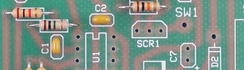
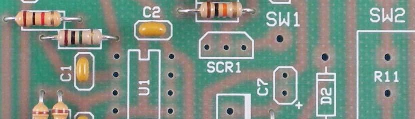
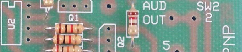
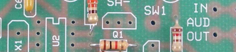
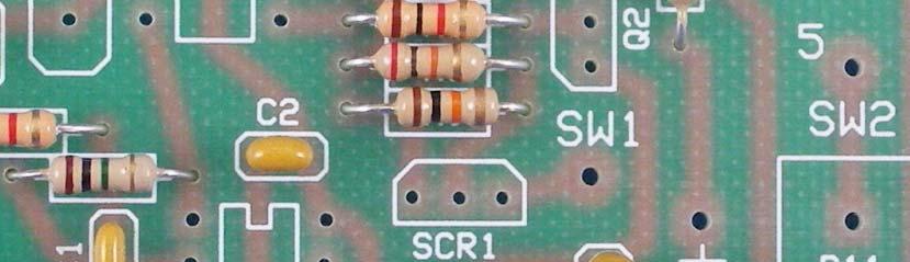
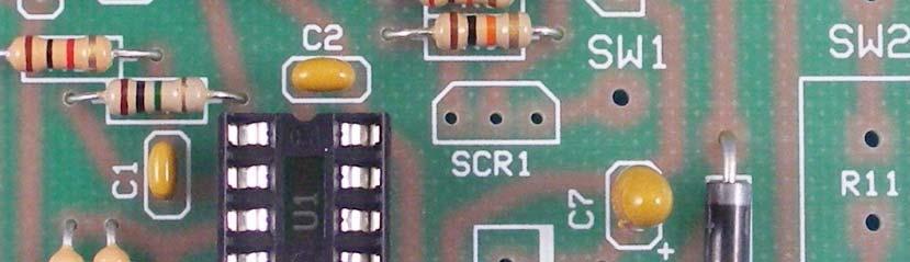
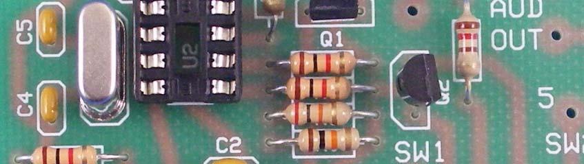
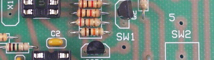
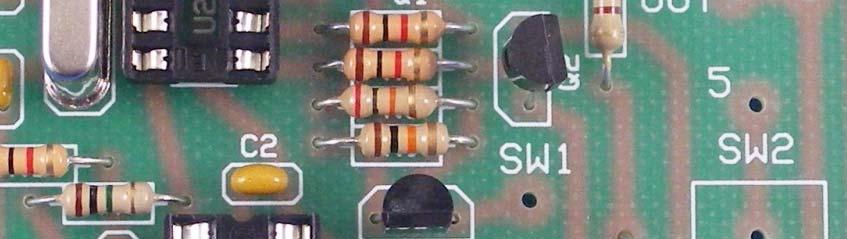
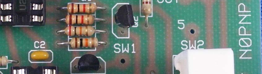
1 Tools Required: ARES Tone Sequential Tone Decoder Kit Assembly nstructions 3/8 Electric Drill Soldering ron Wire Strippers Needle Nose Pliers Wire Cutters Ruler 60/40 Solder Phillips Screw Driver /8, 5/64, 9/3 and 5/6 Drill Bits Masking/Scotch Tape Exacto Knife or Dremel Tool Note: Examine all parts for correct part number and/or polarity markings prior to assembly. Some parts look similar but are not interchangeable and will cause the decoder to fail to operate correctly. Check twice, solder once!! Part : Printed Circuit Board Assembly.. 3. Verify all of the parts received in the kit with the parts list. Using a /8 drill bit, drill and enlarge the 4 corner pads/holes of the circuit board. Locate Resistors R through R0. nsert the resistors into the circuit board at their locations as indicated by the component notations. Solder the 0 connections and trim the leads flush with the board. See ig.. R0 0 ohm Brn-Red-Brn-old R5 330 ohm Org-Org-Brn-old R, R6, R7 K ohm Brn-Blk-Red-old R9 0K ohm Brn-Blk-Org-old R8 0K ohm Red-Blk-Org-old R,R3 00K ohm Brn-Blk-Yel- old R4 M ohm Brn-Blk-rn-old 4. Locate Jumpers JP & JP. The jumpers look like /4W resistors with one black band. nsert the jumpers into the circuit board at their locations as indicated by the component notations. Solder the 4 connections and trim the leads flush with the board. See ig.. 5. Locate Capacitors C, C, C3, C6, and C8. nsert the capacitors into the circuit board at their locations as indicated by the component notations. Solder the 0 connections and trim the leads flush with the board. See ig. 3. JP, JP Blk Band C, C, C3, C6, C8-0. uf (04 Marking)
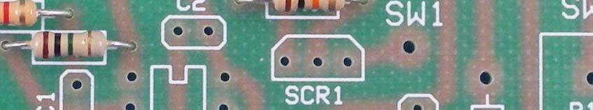
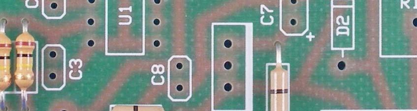
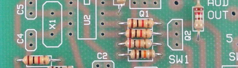
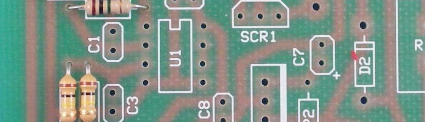
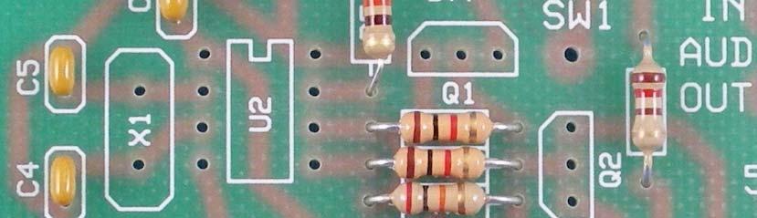
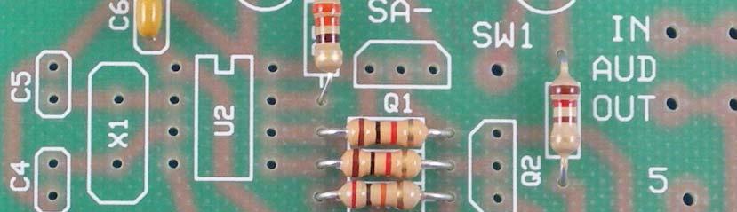
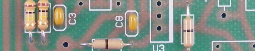
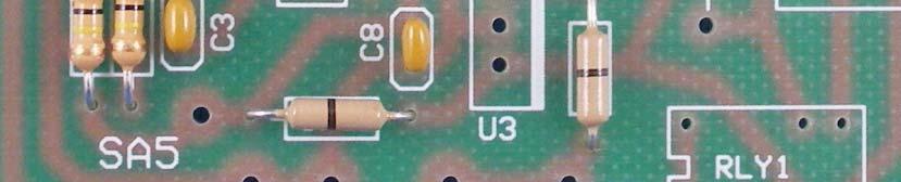
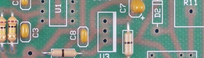
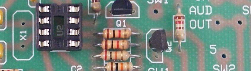
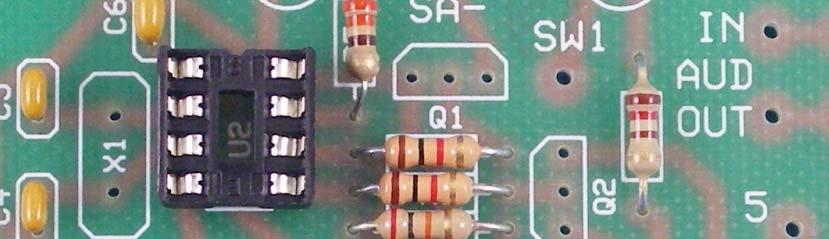
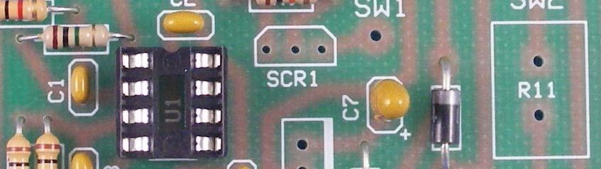
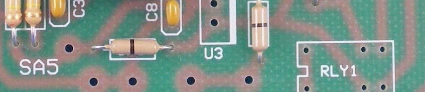
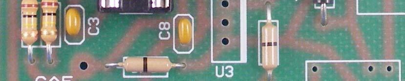
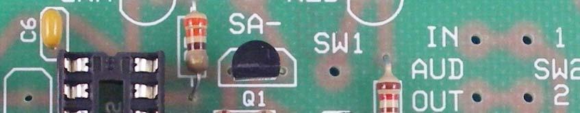
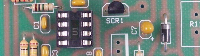
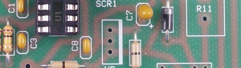
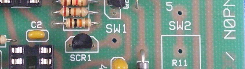
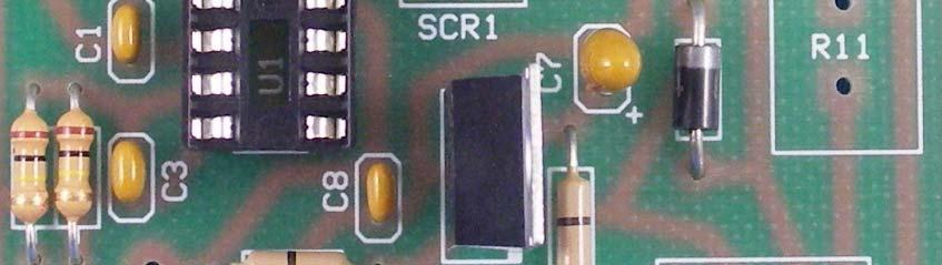
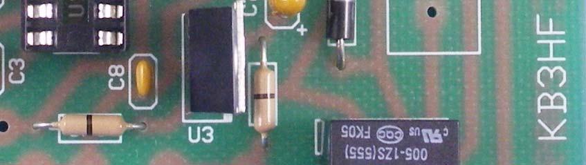
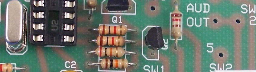
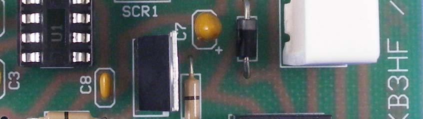
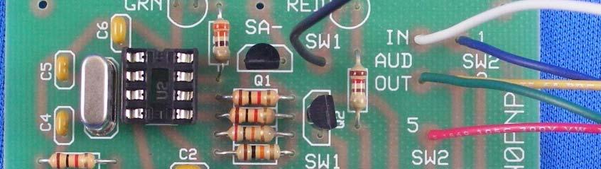
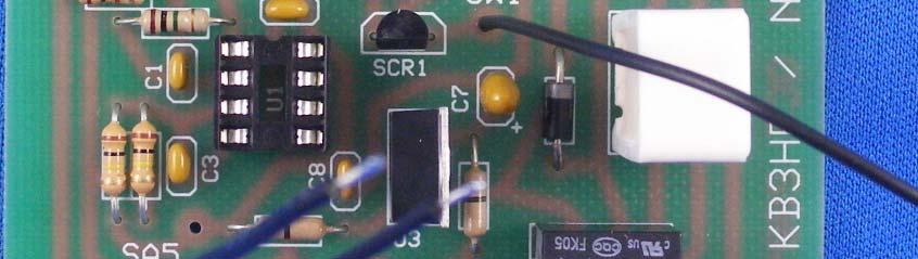
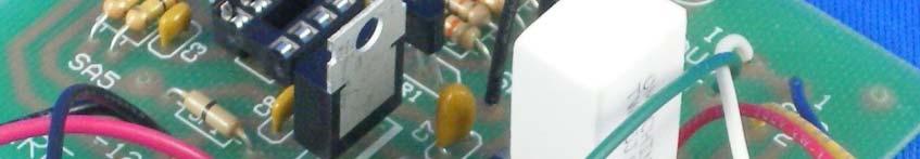
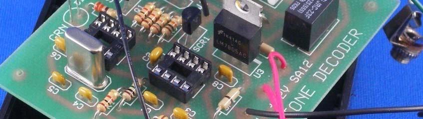
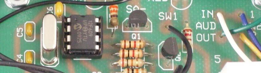
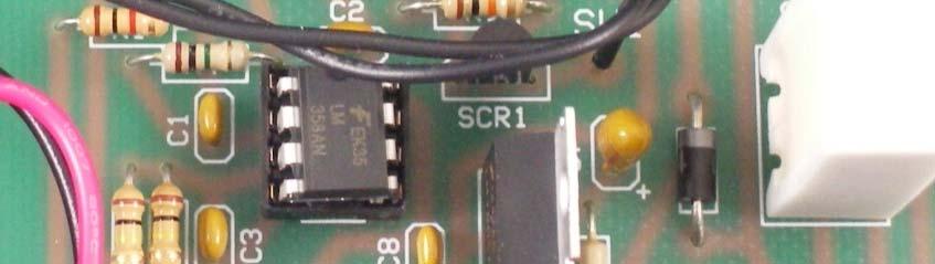
2 6. Locate Capacitors C4 and C5. nsert the capacitors into the circuit board at their locations as indicated by the component notations. Solder the 4 connections and trim the leads flush with the board. See ig Locate Tantalum Capacitor C7. nsert the capacitor into the circuit board paying attention to the correct polarity component notation. Solder the leads and trim the leads flush with the board. See ig. 5. C4, C5 - pf (J Marking) 8. Locate Diode D. nsert the diode into the circuit board paying attention to the correct polarity component notation. Solder the leads and trim the leads flush with the board. See ig. 6. C7-4.7 uf (Observe + Marking) D - N Locate the two 8 pin DP Sockets. Place the at U and U locations. Locate the notch of the socket as indicated on the circuit board. Solder the 6 connections. Do not trim leads. See ig Locate Transistors Q and Q. Locate the flat of the transistor according to the flat as indicated on the component notations. Solder the 6 connections and trim the leads flush with the board. See ig. 8. Q, Q N3904. Locate SCR SCR. nsert the SCR into the circuit board at their locations as indicated by the component notations. Locate the flat of the SCR according to the flat as indicated on the circuit board. Solder the 3 connections and trim the leads flush with the board. See ig. 9. SCR N506. Locate Crystal X. nsert the crystal into the circuit board at the location indicated by the component notation. Solder the connections and trim the leads flush with the board. See ig. 0. X 4 MHz 3. Locate the 3 Terminal 5V Regulator U3. Place in the circuit board at location U3. Orient the tab as indicated by the thick bar on the board notation. Solder the 3 connections and trim the leads flush to the board. See ig.. U3 7805T
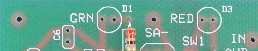
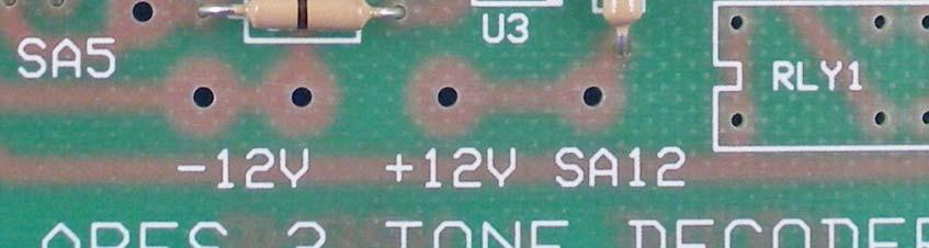
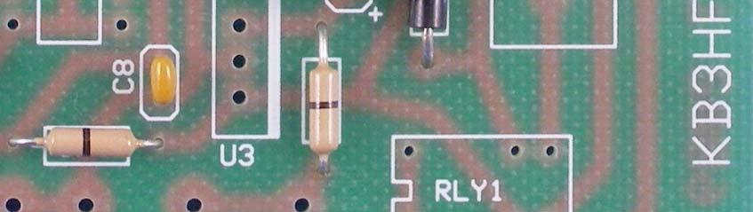
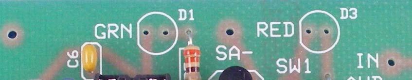
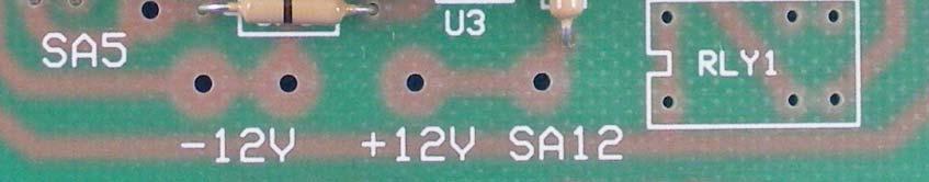
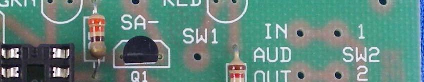
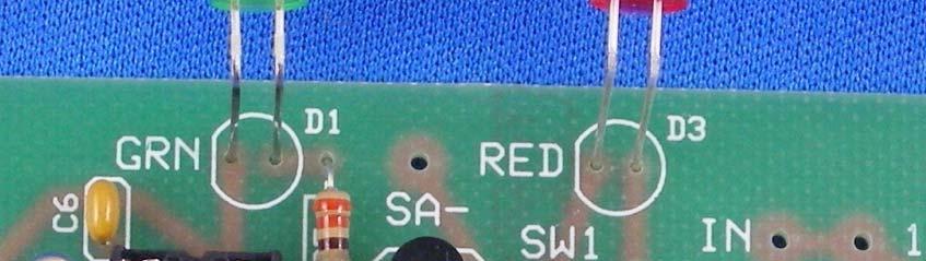
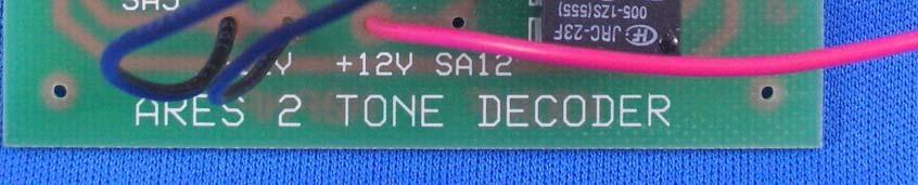
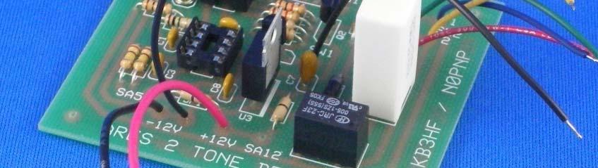
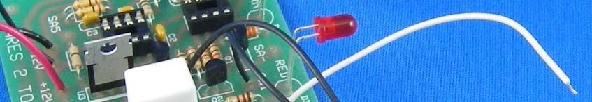
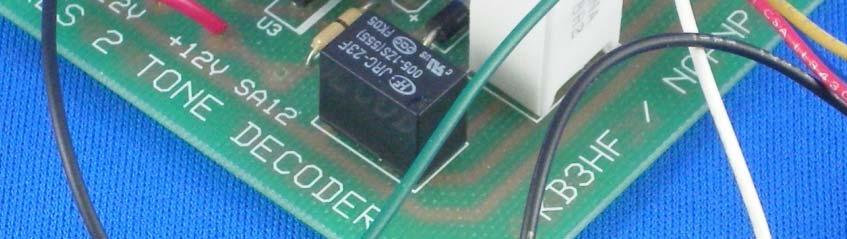
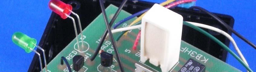
3 4. Locate DP Relay RLY. Place the relay in the circuit board and solder the 6 connections. Do not trim the leads. See ig.. RLY - 5. Locate Power Resistor R. Place the resistor in the circuit board and solder the connections. Trim the leads flush with the boards. See ig. 3. R 8. Ohms 5W 6. Locate LEDs D and D3. Locate the flat on the bottom diameter of the LED body. Hold the LED in your left fingers, small flat facing you, and bend the two leads 90 degrees downward approximately /4 from the bottom of the LED body. nsert the LEDs into the circuit board at their locations as indicated by the component notations. Locate the lead nearest the small flat on the LED body as indicated. Space the LEDs approximately 5/8 above the board and solder the 4 connections. Trim the leads flush with the board. When you are done, the two LEDs should face away from the board at a right angle about 5/8 above the board. See ig. 4. Double check to be sure the LEDs are properly located by the small flat on the flange of the LED body. D reen D3 Red (Clear Body) 7. Measure and cut the following wires. Strip each end /8, twist tightly, and tin each end lightly with solder. Solder each wire into the circuit board as described. Refer to ig Red AW at +V pad. 3 Black AW at -V pad. 3 Black 6 AW at -V pad. 3-/ Black 6 AW at SW pad. 3-/ Black 6 AW at SW pad. Blue 6 AW at SW- pad. Yellow 6 AW at SW- pad. -/ Red 6 AW at SW-5 pad. 3-/ White 6 AW at AUD N pad. 3-/ reen 6 AW at AUD OUT pad. 8. This completes the circuit board assembly except for the sound buzzer. Set the board aside for now.
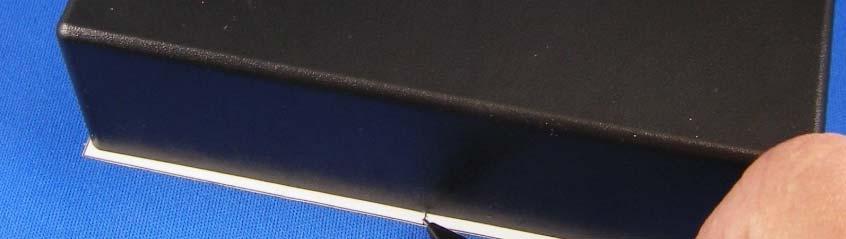
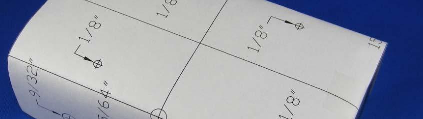
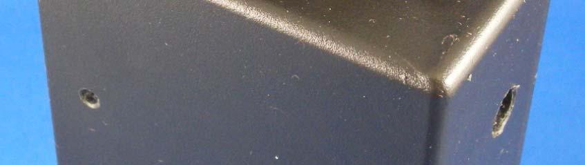
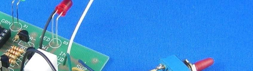
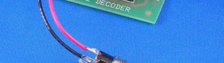
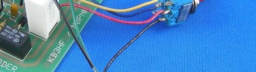
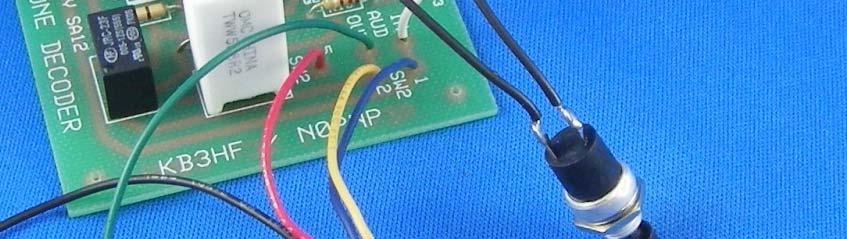
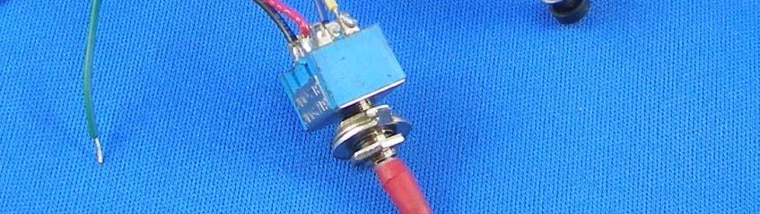
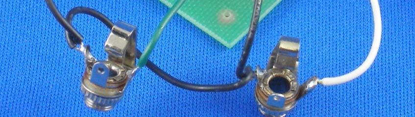
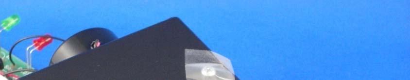
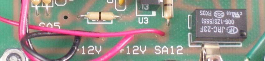
4 Part : Project Box Drilling Locate the drilling template enclosed. Place the plastic box upside down on the center area of the template. Using a pencil, mark the center line point on each of the 5.3 long sides. Refer to ig. 6. Cut out the template around the perimeter of the drawing. Align one side of the template with the top edge of the box and tape in place. Be sure to align the pencil center mark with the center line of the template. Wrap the template around the bottom and bring it up flush with the top edge of opposite side of the box. Align the center line with the pencil center mark and tape in place. Refer to ig. 7. Using a center punch or awl, mark the center of each hole location on the box. Do not hammer as you may crack the box. Remove the template and save for reference. Drill the holes indicated on the template. Drill bits needed are /8, 5/64, 9/3 and 5/6. t s best to drill all of the holes with the /8 bit and follow with the larger bit to complete the proper hole size. f using the Piezo Sound enerator, mark and drill the two mounting holes and wire entry hole in the side panel using the piezo generator as a template. Drill the 3 holes with a /8 drill bit. Refer to ig. 8. Part 3: inal Assembly. Locate the DC Power Jack. Solder the Black and Red ga. wires from the +V and -V connections on the pc board to the jack terminals as shown in ig Locate the DPDT Toggle Switch (SW). Solder the Red, Yellow and Blue 6 ga. wires from the SW connections on the pc board to the switch terminals as shown in ig. 0. Refer to the schematic for terminal number locations. Cut and strip a 3- / Black 6 ga. wire and solder to terminal 6 of the switch. Be careful not to overheat the connections and melt the switch. Locate the Push Button Switch (SW). Solder the two Black 6 ga. wires connected to the SW locations on the circuit board to the switch. t does not matter which switch terminal is used. Refer to ig.. Note: The following two steps require close examination of the jack terminals. Be sure that the tip connector is the audio hot lead (reen or White Leads) and that the ground terminal is use for the black wires. The third shorting terminal is not used. Jacks can come in different orientations as compared to the picture, so examine the jack for the correct connections. ailure to connect to the correct terminal may short the audio output.
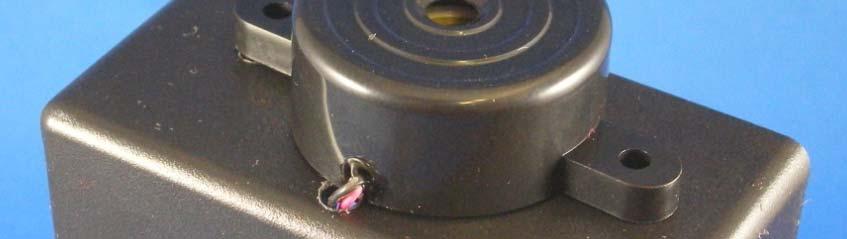
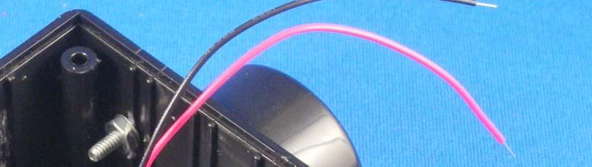
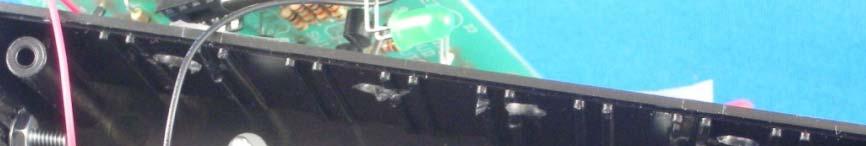
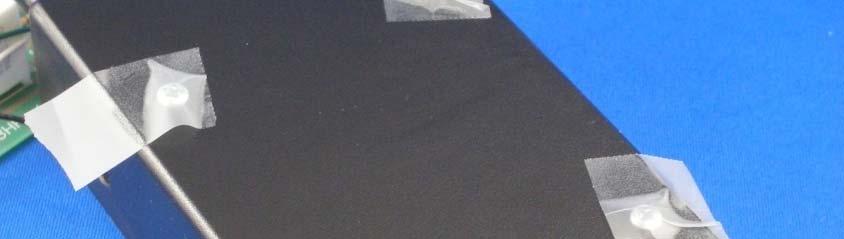
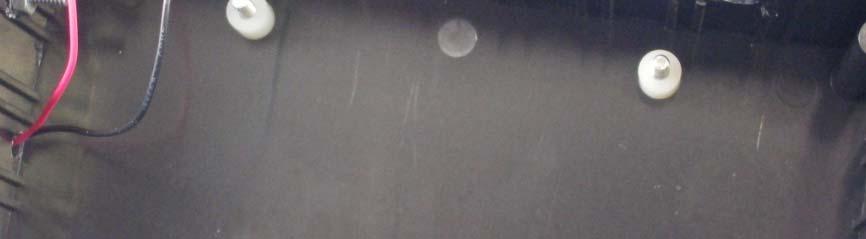
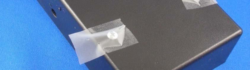
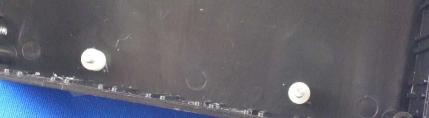
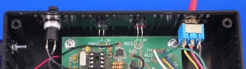
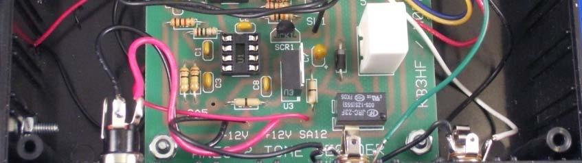
5 4. 5. Locate a 3.5 mm jack. Solder the white 6 ga. wire from the Audio n connection on the pc board to the tip connection as shown in ig. Cut and strip a Black 6 ga. wire. Twist this wire together with the Black 6 ga. wire from the switch. Solder both wires to the ground connection of the jack. Refer to ig.. Be sure that you examine the jack for the correct hot & ground connection tabs. ently bend the terminals outward to clear the center area if needed. Be sure wires don t protrude into the plug area. Locate the second 3.5 mm jack. Solder the reen 6 ga. wire from the Audio Out connection on the pc board to the tip connection of the second 3.5 mm jack. Twist together the Black 6 ga. wire from the first 3.5mm jack and the Black 6 ga. wire from the -V connection on the pc board. Note: ig. depends on type of Jack purchased. Be sure to verify correct hot and round terminals. Solder these wires to the ground connection of the 3.5mm jack. Refer to ig.. ently bend the terminals outward to clear the center area if needed. Be sure wires don t protrude into the plug area. Note: The project box has internal ribs. f the drill holes are in the area of the ribs, use an Exacto Knife or Dremel Tool to remove the ribs flush to the wall of the box. This makes the LEDs and jacks mount flat and easily. Do not try to mount on a rib as the jack will come loose or rotate. 6. Mount the sound buzzer on the side panel using two 4-40 x 5/8 screws, lock washers and nuts. eed the two wires through the panel to the inside of the box. Refer to ig Retrieve pc board assembly. Solder the Red sound buzzer lead to the SA pad on the pc board. Solder the Black sound buzzer lead to the SA- pad on the pc board. Refer to ig. 4. (f you purchased a 5V sound buzzer, connect the positive lead to SA5 pad on the circuit board) Locate four 4-40 x 5/8 screws and insert from the bottom panel of the box. Hold the screws in place by placing a piece of tape over the screw heads. Refer to ig Turn the box over and place four ¼ spacers on the screws. Refer to ig Place the pc board on the spacers and carefully feed the two LEDs into the bezels in the front panel. Be sure the leads do not touch each other. Secure the pc board with four 4-40 lock washers and nuts. Refer to ig. 7.. Mount the two switches and the 3 jacks into the holes in the box. Tighten the nuts securely. Refer to ig. 7 for the orientation of the toggle switch.. Place the front and back labels on the box as shown in igs. 8 and 9. Place the 4 Vinyl oot Pads at the corners of the box just inside of the round molded pads in the bottom of the box.
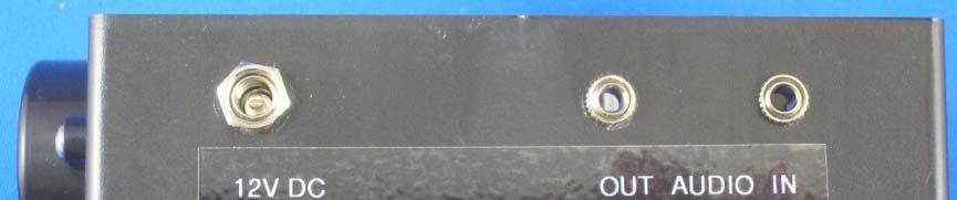
6 Part 4: Test & Checkout Make a V DC power cable using the.5mm DC Plug provided and your user supplied wire (not part of the kit). Make an Audio Jumper for the radio to decoder audio connection using the two 3.5mm mono plugs provided and your user supplied wire (not part of the kit). Plug the V DC cable into the V nput Jack on the back of the box. Connect the negative test lead of a DC Voltmeter to the black wire on the DC Jack. Check for voltages at the following points: U Pin 8: +5VDC U Pin : +5VDC Note: f you do not measure the correct voltage or have voltage at an incorrect level, DO NOT PROCEED until the problem is corrected. Damage to the chips will occur if voltages are not correct! Place the front audio toggle switch in the On position. Using an Ohmmeter, check for continuity between the white and green wires on the two audio jacks. Place the front audio toggle switch in the Mute position. Using an Ohmmeter, check for 8. ohms between the black and white wires of the audio input jack. Make a short wire jumper from any of the remaining wires in the kit. Using this jumper, connect U Pin to the following pins: a. U-Pin 5: Relay should click. b. U-Pin 6: Piezo Tone enerator should sound and Red LED should begin to flash. Remove jumper, and Red LED should continue to flash and Piezo Tone enerator should stop sounding. f the Red LED does not continue to blink, add the remaining K resistor to the RX location on the circuit board (RX not shown in pictures) to keep the SCR latched and the LED blinking. (Note: There will be a low level tone until reset.) Press the front Reset push button and Red LED should turn off. c. U-Pin 7: reen LED should turn on. Remove jumper and reen LED should turn off. 8. Remove VDC cable from the unit. This completes the initial checkout of the unit.
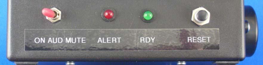
7 9. This part is static sensitive. Be sure you are not full of static electricity before handling the part. Carefully align the pins of the LM358 Op Amp to the U socket and push the C into the socket. Be sure that Pin (Dot/Notch) of the C matches the notch in the end of the socket. Refer to ig. 30. ailure to insert the C correctly can damage the C. Check to be sure the 8 leads are properly inserted and not bent over or under the C or socket. 0. This part is static sensitive. Be sure you are not full of static electricity before handling the part. Carefully align the pins of the 609 PC Microprocessor to the U socket and push the C into the socket. Be sure to Pin Dot/Notch) of the C matches the notch in the socket. Refer to ig. 3. ailure to insert the C correctly can damage the C. Check to be sure the 8 leads are properly inserted and are not bent over or under the C or socket.. Place the plastic lid on the box and attach with the 4 screws provided with the box. This completes the assembly and test of the ARES Two Tone Sequential Decoder. Using the Two Tone Sequential Decoder Locate the decoder near your transceiver. Plug one end of the audio patch cable you constructed to the Speaker Output jack on your transceiver. Connect the other end of the cable to the Audio nput jack on the Decoder. Plug an external speaker into the audio output jack. Place the Audio toggle switch in the On position and check for audio from the transceiver by opening the squelch. f squelch noise is heard in the speaker, you have a good audio connection. Adjust the volume control for comfortable listening level. Do not over drive the audio level. The Mute position of the audio toggle switch will turn off the audio from the radio until an alert is received. You can use the decoder in either switch position. Connect the VDC cable to your station power supply and plug the cable into the VDC jack on the rear of the box. The reen LED should turn on signifying that the unit is ready to decode an alert. When an alert is received, the RED LED will begin to flash, the Piezo Tone enerator will sound for a 6 seconds, and the speaker audio will turn on if the audio switch is in the Mute position for approximately 60 seconds. This will allow you to listen to the alert instructions. After 60 seconds, the audio will mute. The Red LED will continue to flash to show an alert was received. Press the Reset push button to turn off the Red LED after an alert. Caution: This decoder has the audio output referenced to ground. f you have a radio that has an isolated audio output (not referenced to ground), you must use an audio isolation transformer. Connecting the decoder directly to that type of radio will damage the radio!
8 3 4

9
10 9 0


11


12


13 3 4
14


15
16 ARES Tone Sequential Decoder Parts List Designation QTY Part Value C,C,C3,C6,C8 5 Capacitor. u C4, C5 Capacitor p C7 Capacitor, Tant 4.7 u D Diode N4004 Q,Q Transistor N3904 JP, JP Jumper 0 Ohms R0 Resistor 0 Ohms R5 Resistor 330 Ohms R, R6, R7, RX 4 Resistor K Ohm R9 Resistor 0K Ohm R8 Resistor 0K Ohm R, R3 Resistor 00K Ohm R4 Resistor M Ohm R Resistor 8. Ohms 5W SCR SCR N506 U Op Amp LM358AN U Microprocessor 609 U3 Voltage Regulator LM7805T X Crystal 4MHz D3 LED RED T-3/4 D LED RN T-3/4 SW Push Button N.C. SW Toggle Switch DPDT SA Tone enerator SONALERT RLY Relay Relay SPDT Relay (Alternate) Relay SPDT LED Mount T-3/4 Dip Socket 8 Pin J3 DC Jack V Coaxial P3 DC Plug V Coaxial Plug J, J Jack 3.5 mm Mono P, P Plug 3.5mm Mono Enclosure 6"x3"x" 4 eet Stickon PC Board Rev. 4 Spacers Nylon #4 Hole 6 Screw 4-40x5/8" 6 Nuts Lock Washer a. Wires Blk, Red, Yel, rn, Blu, Wht a Wires Blk, Red Labels
17
18 ARES Tone Sequential Decoder Parts List Designation QTY Part Value Source Part No. C,C,C3,C6,C8 5 Capacitor. u DigiKey ND C4, C5 Capacitor p DigiKey BC005CT-ND C7 Capacitor, Tant 4.7 u uturlec C0047UT D Diode N4004 All Electronics N4004 Q,Q Transistor N3904 uturlec N3904 JP, JP Jumper 0 Ohms DigiKey 0.0QBK-ND R0 Resistor 0 Ohms DigiKey 0QBK-ND R5 Resistor 330 Ohms DigiKey 330QBK-ND R, R6, R7, RX 4 Resistor K Ohm DigiKey.0KQBK-ND R9 Resistor 0K Ohm DigiKey 0KQBK-ND R8 Resistor 0K Ohm DigiKey 0KQBK-ND R, R3 Resistor 00K Ohm DigiKey 00KQBK-ND R4 Resistor M Ohm DigiKey.0MQBK-ND R Resistor 8. Ohms 5W DigiKey TWW5J8RE-ND SCR SCR N506 DigiKey N506OS-ND U Op Amp LM358AN DigiKey LM358ANS-ND U Microprocessor 609 DigiKey PC609-/P-ND U3 Voltage Regulator LM7805T uturlec 7805T X Crystal 4MHz DigiKey X97-ND D3 LED RED T-3/4 uturlec LED5RL D LED RN T-3/4 uturlec LED5 SW Push Button N.C. All Electronics MPB-5 SW Toggle Switch DPDT uturlec DPDT SA Tone enerator SONALERT DigiKey ND RLY Relay Relay SPDT uturlec JRC-3-05 Relay (Alternate) Relay SPDT DigiKey PB07-ND LED Mount T-3/4 All Electronics HLED-4 Dip Socket 8 Pin uturlec CS8 J3 DC Jack V Coaxial uturlec DCCHM4 P3 DC Plug V Coaxial Plug uturlec DCPWR004 J, J Jack 3.5 mm Mono uturlec P035SCK00 P, P Plug 3.5mm Mono uturlec P035MB Enclosure 6"x3"x" All Electronics MB-3 4 eet Stickon DigiKey SJ ND PC Board Rev. uturlec Custom Design 4 Spacers Nylon #4 Hole DigiKey 876K-ND 6 Screw 4-40x5/8" DigiKey H348-ND 6 Nuts 4-40 DigiKey H6-ND 6 Lock Washer 4-40 DigiKey H36-ND 6 a. Wires Blk, Red, Yel, rn, Blu, Wht a Wires Blk, Red Labels Rev. September 009
19
20
Pacific Antenna Two Tone Generator
 Pacific Antenna Two Tone Generator Description Our Two Tone Generator kit provides two non-harmonic, sine wave signals for testing audio circuits Outputs of approximately 700Hz and 1900Hz and the combination
Button Code Kit. Assembly Instructions and User Guide. Single Button Code Entry System
 Button Code Kit Single Button Code Entry System Assembly Instructions and User Guide Rev 1.0 December 2009 www.alan-parekh.com Copyright 2009 Alan Electronic Projects Inc. 1. Introduction... 4 1.1 Concept
*on-board power supply capability limited. External battery should be used for higher power servos.
 Pan and Tilt Decoder II PART NO. Add affordable Pan and Tilt control to your security cameras using the Pan and Tilt Decoder II and the DFRobot DF05BB Tilt/Pan Kit (5kg), Jameco PN 2144518 or the DAGU
TinyTrak4 Kit Hardware Manual
 TinyTrak4 Kit Hardware Manual Version 0.7 July 23, 2017 Overview TinyTrak4 is a radio controller similar to a packet TNC, which can transmit and receive signals over a two-way radio. It can receive and
Microsystems. SCI-6 Sound Card Interface Kit Version 1.09 January 2015
 UM Unified Microsystems SCI-6 Sound Card Interface Kit Version 1.09 January 2015 The SCI-6 interface was designed to be a low cost, high quality interface between your PC s sound card and radio transceiver.
Pacific Antenna Easy TR Switch Kit
 Pacific Antenna Easy TR Switch Kit Kit Description The Easy TR Switch is an RF sensing circuit with a double pole double throw relay that can be used to automatically switch an antenna between a separate
4.1 Parts and Components... IV Assembly Tips... IV Assembly Precautions... IV Required Tools, Equipment and Materials..
 IV PERSONALITY MODULE ASSEMBLY 4.1 Parts and Components............ IV-1 4.2 Assembly Tips............... IV-1 4.3 Assembly Precautions............ IV-1 4.4 Required Tools, Equipment and Materials.. IV-1
Universal Keying Adapter 3+
 Universal Keying Adapter 3+ The Universal Keying Adapter Version 3+ kit will allow you to key nearly any transmitter or transceiver with a straight key, electronic keyer, computer serial or parallel port
Insert the male, 90 angled, 2x10 connectors into the corresponding 2x10 sockets and put them in place, flat under the PCB. Solder.
 MC624 Assembly guide Safety warning The kits are main powered and use potentially lethal voltages. Under no circumstance should someone undertake the realisation of a kit unless he has full knowledge about
SM010, Assembly Manual PCB Version 1.0
 180 SM010, Assembly Manual MATRIXARCHATE 16 8 IO SEQUENTIAL MATRIX SIGNAL ROUTER SM010 1 2 1 2 3 4 5 3 4 5 6 7 8 9 10 11 12 6 7 8 9 10 11 12 13 14 15 16 PROGRAM A B C D E F G H f1 f2 20.000 180 SSSR Labs
EE 354 August 1, 2017 Assembly of the AT89C51CC03 board
 EE 354 August 1, 2017 Assembly of the AT89C51CC03 board The AT89C51CC03 board comes as a kit which you must put together. The kit has the following parts: No. ID Description 1 1.5" x 3.25" printed circuit
ARRL ETP Solder Hour Clock Kit Construction Manual
 ARRL ETP Solder 101 24-Hour Clock Kit Construction Manual Do a complete parts check cross checking the individual parts against the parts list. Pay particular attention to the color code for the resistors:
High Power (15W + 15W) Stereo Amplifier
 Stereo Amplifier") High Power (15W + 15W) Stereo Amplifier Build Instructions Issue 1.0 Build Instructions Before you put any components in the board or pick up the soldering iron, just take a look at the Printed Circuit
High Power (15W + 15W) Stereo Amplifier Build Instructions Issue 1.0 Build Instructions Before you put any components in the board or pick up the soldering iron, just take a look at the Printed Circuit
RC-210 Repeater Controller Assembly Manual
 Arcom Communications 24035 NE Butteville Rd Aurora, Oregon 97002 (503) 678-6182 arcom@ah6le.net RC-210 Repeater Controller Assembly Manual Hardware Version 3.0 Original Release Date September 13, 2004
Installation/assembly manual for DCC/Power shield
 Installation/assembly manual for DCC/Power shield The DCC circuit consists of the following components: R1/R6 R2/R3 R4/R5 D1 C2 2 kω resistor ½ Watt (colour code Red/Black/Black/Brown/Brown) 10 kω resistor
K8099 NIXIE CLOCK. * optional enclosure TKOK19 (black) - TKOK17 (white) ** optional plexiglass enlcosure B8099 ILLUSTRATED ASSEMBLY MANUAL
 - TKOK17 (white) ** optional plexiglass enlcosure B8099 ILLUSTRATED ASSEMBLY MANUAL") Total solder points: 230 + 74 Difficulty level: beginner 1 2 3 4 5 advanced NIXIE CLOCK K8099 ** * A unique combination of both vintage and modern electronics ILLUSTRATED ASSEMBLY MANUAL H8099IP-1 * optional
Total solder points: 230 + 74 Difficulty level: beginner 1 2 3 4 5 advanced NIXIE CLOCK K8099 ** * A unique combination of both vintage and modern electronics ILLUSTRATED ASSEMBLY MANUAL H8099IP-1 * optional
An open-source hardware+software project. For design files and additional documentation, please visit:
 An open-source hardware+software project. For design files and additional documentation, please visit: http://www.evilmadscientist.com/go/diavolino Support: http://www.evilmadscientist.com/forum/ Distributed
SRI-02 Speech Recognition Interface
 SRI-02 Speech Recognition Interface Data & Construction Booklet The Speech Recognition Interface SRI-02 allows one to use the SR-07 Speech Recognition Circuit to create speech controlled electrical devices.
The Sudden Storm Kit. by QRPme. Builder s Guide. version4.2. for. Sudden Storm ][ Ver4 (red pcb) Updated 01/10/2012
![The Sudden Storm Kit. by QRPme. Builder s Guide. version4.2. for. Sudden Storm ][ Ver4 (red pcb) Updated 01/10/2012](/thumbs/75/72448638.jpg "The Sudden Storm Kit. by QRPme. Builder s Guide. version4.2. for. Sudden Storm ][ Ver4 (red pcb) Updated 01/10/2012") The Sudden Storm Kit by QRPme Builder s Guide version4.2 for Sudden Storm ][ Ver4 (red pcb) Updated 01/10/2012 Open the can and the adventure begins 1 Organize the parts and take an inventory Bill of Materials
The Sudden Storm Kit by QRPme Builder s Guide version4.2 for Sudden Storm ][ Ver4 (red pcb) Updated 01/10/2012 Open the can and the adventure begins 1 Organize the parts and take an inventory Bill of Materials
Sierra Radio Systems. Making a Keyer with the. HamStack. Project Platform
 Sierra Radio Systems Making a Keyer with the HamStack Project Platform Introduction The HamStack Project Board includes primary interface elements needed to make a high quality CW keyer. Using the LCD
Bill of Materials: Picaxe-based IR Control Module Pair PART NO
 Picaxe-based IR Control Module Pair PART NO. 2171014 The IRGEII is an IR (Infra Red) Transmitter and Receiver pair that uses a 38 KHZ frequency of invisible light to communicate simple instructions. The
Parts List: Part # Tools List: Instructions:
 Parts List: Part # 1 pair of Dayton Audio B652s 300-652 1 Dayton Audio DTA-2 amplifier 300-385 1 MP3 module 320-350 1 7805 +5 VDC voltage regulator 7805 1 12 VDC 2A power supply 129-077 1 2.1 mm panel
EQ573 Assembly guide. EQ573 Assembly guide Main board 1. Diodes. 2. Resistors (1) 3. Test pins. 4. Ceramic capacitors.
 3. Test pins. 4. Ceramic capacitors.") EQ573 Assembly guide Safety warning The kits are main powered and use potentially lethal voltages. Under no circumstance should someone undertake the realisation of a kit unless he has full knowledge about
EQ573 Assembly guide Safety warning The kits are main powered and use potentially lethal voltages. Under no circumstance should someone undertake the realisation of a kit unless he has full knowledge about
Uzebox Kit Assembly Guide
 Uzebox Kit Assembly Guide V1.3 Page 1 of 18 Revision History Version Date Author Description 1.0 01-Nov-2012 A.Bourque Initial release 1.1 6-Nov-2012 A.Bourque Minor corrections 1.2 28-Jan-2014 A.Bourque
Figure 1. The completed programming kit List of Parts
 Many NearSys kits are programmed through a three pin header soldered to the PCB. Since a three pin receptacle is not a common termination for a serial cable, this kit contains the parts to make one. In
Quicksilver 606 TR-606 CPU Upgrade
 Quicksilver 606 TR-606 CPU Upgrade D650C 128 Installation Guide Social Entropy Electronic Music Instruments TABLE OF CONTENTS WARNINGS... 1 OVERVIEW... 2 WHAT'S IN THE BOX... 3 OPENING THE TR-606 CASE...
Morse Code Practice Oscillator
 Features Description Keyer speed range: Limited only by keying source True Sine wave tone output Tone Volume Control Tone Frequency Control Internal Speaker 1/8 External Speaker/Headphone Jack RCA Key
Schematic Diagram: R2,R3,R4,R7 are ¼ Watt; R5,R6 are 220 Ohm ½ Watt (or two 470 Ohm ¼ Watt in parallel)
") Nano DDS VFO Rev_2 Assembly Manual Farrukh Zia, K2ZIA, 2016_0130 Featured in ARRL QST March 2016 Issue Nano DDS VFO is a modification of the original VFO design in Arduino Projects for Amateur Radio by
Nano DDS VFO Rev_2 Assembly Manual Farrukh Zia, K2ZIA, 2016_0130 Featured in ARRL QST March 2016 Issue Nano DDS VFO is a modification of the original VFO design in Arduino Projects for Amateur Radio by
Seeburg JCU-DEC Kit Convert Your Seeburg DEC Wallbox Into a Jukebox
 Seeburg JCU-DEC Kit Convert Your Seeburg DEC Wallbox Into a Jukebox MP3 Compact Flash Player Coin Operated or Free Play Integrated Power Amplifier Line-Out to External Amplifier Programmable Autoplay IR
RC210 Repeater Controller Assembly Manual
 Arcom Communications 24035 NE Butteville Rd Aurora, Oregon 97002 (503) 678-6182 arcom@ah6le.net http://www.arcomcontrollers.com/ RC210 Repeater Controller Assembly Manual Hardware Version 3.3 Reproduction
GEKCO MODEL CLK056 DIGITAL CLOCK ASSEMBLY & OPERATION MANUAL GEKCO
 GEKCO MODEL CLK056 DIGITAL CLOCK ASSEMBLY & OPERATION MANUAL GEKCO Inc. 1565 SW Cypress Ln McMinnville, OR 97128 (503) 472-4770 P/N 595-325 REV 181030 Copyright c 2018 GEKCO Inc. All Rights Reserved Printed
RC-210 Repeater Controller Assembly Manual
 Arcom Communications 24035 NE Butteville Rd Aurora, Oregon 97002 (503) 678-6182 arcom@ah6le.net RC-210 Repeater Controller Assembly Manual Hardware Version 2.5 Reproduction or translation of any part of
MAIN PCB (The small one)
") THANKS FOR CHOOSING ONE OF OUR KITS! This manual has been written taking into account the common issues that we often find people experience in our workshops. The order in which the components are placed
THANKS FOR CHOOSING ONE OF OUR KITS! This manual has been written taking into account the common issues that we often find people experience in our workshops. The order in which the components are placed
Q2 XBee Handheld Controller Assembly Guide
 Q2 XBee Handheld Controller Assembly Guide Copyright Quantum Robotics Inc. Q2 Controller V1.0 1 Parts List: The kit comes with 14 individual bags. 1. Case Top and Bottom 2. Case Screw Package containing:
TIME WIZARD MULTI CLOCK DIVIDER BUILDING GUIDE
 TIME WIZARD MULTI CLOCK DIVIDER BUILDING GUIDE Table of Contents 0. Components List + Tools 0. PCB Sides 03. PCB Assembly 04_. Diode N448 04_. Laying Resistors 04_3. Capacitors 04_4. Quartz 04_5. 78L05
Sierra Radio Systems. HamStack. Project Board Reference Manual V1.0
 Sierra Radio Systems HamStack Project Board Reference Manual V1.0 Welcome HamStack Project Board Reference Manual Revision 1.0.3 2011 George Zafiropoulos, KJ6VU and John Best, KJ6K This guide provides
Bill of Materials: 8x8 LED Matrix Driver Game PART NO
 8x8 LED Matrix Driver Game PART NO. 2171031 This Game Maker II kit is a game design platform using a single color 8x8 matrix LED without the need for a shift register or expensive Arduino. The kit includes
IQ32 Upgrade Kit Assembly Instructions
 IQ32 Upgrade Kit Assembly Instructions Jim Veatch WA2EUJ September 17, 2018 TABLE OF CONTENTS 1. INTRODUCTION... 3 2. IQ-32 UPGRADE KIT INVENTORY... 4 3. PREPARING THE RS-HFIQ AND SIDE PANELS... 6 4. CONNECTING
3 pyro output datalogger altimeter with an ATmega 328 microcontroller Kit assembly instructions
 3 pyro output datalogger altimeter with an ATmega 328 microcontroller Kit assembly instructions Version date Author Comments 1.0 29/05/2013 Boris du Reau Initial version Rocket Type Micro-max Model Mid
DSP-232 Upgrade Kit A.06113
 DSP-232 Upgrade Kit A.063 Installation and Operation Manual Rev. 2.0 WARRANTY WHO IS COVERED WHAT WE WILL DO WHAT YOU MUST DO WHAT IS NOT COVERED SERVICE WARRANTY HOW TO CONTACT TIMEWAVE TIMEWAVE TECHNOLOGY
Construction Construction Instructions
 Semi-Virtual Diskette SVD Construction Construction Instructions PCB version 2.0 September 2004 Eric J. Rothfus Table of Contents Table of Contents... i Parts List...1 Construction Overview...5 PCB Construction...
AVR-M Rev 5 ASSEMBLY
 AVR-M Rev 5 ASSEMBLY The AVR_M is a very compact self contained Atmel AVR mcu controller board. It includes an onboard serial programmer (via PC com port), an I2C eeprom and can use a Mega163, Mega16 or
GEKCO MODEL CLK036 DIGITAL CLOCK ASSEMBLY & OPERATION MANUAL. GEKCO Inc SW Cypress Ln McMinnville, OR (503) P/N REV 1.
 P/N REV 1.") GEKCO MODEL CLK036 DIGITAL CLOCK ASSEMBLY & OPERATION MANUAL GEKCO Inc. 1565 SW Cypress Ln McMinnville, OR 97128 (503) 472-4770 P/N 595-324 REV 1.0 Copyright c 2018 GEKCO Inc. All Rights Reserved Printed
GEKCO MODEL CLK036 DIGITAL CLOCK ASSEMBLY & OPERATION MANUAL GEKCO Inc. 1565 SW Cypress Ln McMinnville, OR 97128 (503) 472-4770 P/N 595-324 REV 1.0 Copyright c 2018 GEKCO Inc. All Rights Reserved Printed
HARDWARE ASSEMBLY MANUAL
 HARDWARE ASSEMBLY MANUAL P336: System Dynamics Filtering Laboratory Release Date: February 7, 203 P336 Revision: B PURPOSE The purpose of this document is to outline the procedures to be used in order
Assembling the Printed Circuit Board for the EDE1200 Robot
 This board receives instructions from either a CBL2, a LabPro or (with an adapter cable) an original CBL. The board has two 595 shift registers (each providing 8 bits of on-board memory) and two EDE1200
DELUXE STEREO AMPLIFIER KIT
 ESSENTIAL INFORMATION BUILD INSTRUCTIONS CHECKING YOUR PCB & FAULT-FINDING MECHANICAL DETAILS HOW THE KIT WORKS CREATE YOUR OWN SPEAKER DOCK WITH THIS DELUXE STEREO AMPLIFIER KIT Version 2.0 Build Instructions
Section 5: Installing Parts from the Controls and Connectors Bag
 Section 5: Installing Parts from the Controls and Connectors Bag 1) Install Pinheaders & Sockets Using the Component Layout Diagram in Appendix A as a guide, install all pinheaders and strip sockets on
KEYLITE. Specifications: The Keylite keys your rig with paddles or an IBM compatible Keyboard. Power Requirements: 9V-14V
 KEYLITE The Keylite keys your rig with paddles or an IBM compatible Keyboard. Specifications: Power Requirements: 9V-14V Maximum current draw: Less than 20ma plus Keyboard. Keyboard input: Standard IBM
TECHKNOW, INC. Kiosk Order Confirmation System INSTALLATION MANUAL. Revision Date: July 11, 2012 Part # Version 3.2
 document Page 1 of 18 TECHKNOW, INC Kiosk Order Confirmation System INSTALLATION MANUAL Revision Date: July 11, 2012 Part # Version 3.2 Techknow, Inc. 393 Mayfield Road Duncan, SC 29334 www.gotechknow.com
A Backlighted LCD for your K1
 A Backlighted LCD for your K1 (K1BKLTKIT) Tom Hammond - NØSS, July 27, 2006 Rev C Thanks to Wayne Burdick, N6KR for suggesting this implementation of backlighting the K1 display. APPLICABILITY This modification
Elecraft K3 KPA3 Power Connector Replacement Revision B, June 30, 2017 Copyright 2017, Elecraft, Inc. All Rights Reserved
 Introduction Elecraft K3 KPA3 Power Connector Replacement Revision B, June 30, 2017 Copyright 2017, Elecraft, Inc. All Rights Reserved The connectors furnishing high current to the KPA3 module have failed
Sandevices E681 RGB Pixel Controller Assembly Manual
 Sandevices E681 RGB Pixel Controller Assembly Manual Oct 22, 2011 Oct 30, 2011 Initial Release Added component illustrations, silkscreen images, and misc text changes Prior electronic assembly experience
Assembly Instructions for the KA Electronics Elliptic Equalizer
 Assembly Instructions for the KA Electronics Elliptic Equalizer Install IC sockets Elliptic Equalizer PC Board Stuffing Guide Place the PC Board on the work bench silkscreen side face up. Place twelve
Uzebox Kit Assembly Guide
 Uzebox Kit Assembly Guide V1.7 Page 1 of 21 Revision History Version Date Author Description 1.0 01-Nov-2012 A.Bourque Initial release 1.1 6-Nov-2012 A.Bourque Minor corrections 1.2 28-Jan-2014 A.Bourque
Single cable kit for the FCB1010
 Single cable kit for the FCB1010 1. What is it? With this kit, you can turn your FCB1010 into a phantom powered floorboard, which can do 2-way MIDI communication over one single cable. After installing
DIY PROJECT CS520 Wireless Headset to Cell Phone or Tablet Adapter Box
 DIY PROJECT CS520 Wireless Headset to Cell Phone or Tablet Adapter Box Gene Hinkle, K5PA 8/16/2017 Also Check Out the CS520 Resource Page http://cs520hams.k5pa.com Rationale for Using CS520 With Your Cell
Reverse DDS Kit Construction
 Reverse DDS Kit Construction This kit is only recommended for home constructors experienced with Surface Mount construction so these notes are for guidance only. Mark out and drill the holes for the SMA
HARDWARE OPERATIONS MANUAL
 HARDWARE OPERATIONS MANUAL Table of Contents INTRODUCTION... 2 SECTION 1: HARDWARE COMPONENT ASSEMBLIES... 2 MECHANICAL HARDWARE AND CASE... 2 PCB ASSEMBLY... 4 ISD RECORDING CIRCUIT... 5 BREADBOARD ASSEMBLY...
IR TRANSMITTER BLOK PCB ASSEMBLY INSTRUCTIONS. Copyright EduTek Ltd Rev. 2
 IR TRANSMITTER BLOK PCB ASSEMBLY INSTRUCTIONS Copyright EduTek Ltd Rev. 2 Circuit Details The circuit is shown below with a parts list of components. Check through this list and identify each component.
QRPGuys Single Lever Keyer/Paddle
 QRPGuys Single Lever Keyer/Paddle First, familiarize yourself with the parts and check for all the components. If a part is missing, please contact us and we will send one. You must use qrpguys.parts@gmail.com
QRPometer Assembly Manual Copyright 2012 David Cripe NM0S The 4 State QRP Group. Introduction
 QRPometer Assembly Manual Copyright 2012 David Cripe NM0S The 4 State QRP Group Introduction Thank you for purchasing a QRPometer. We hope you will enjoy building it and and find it a useful addition to
StationPro II Network Manual rev. 06/27/2010
 StationPro II Network Manual rev. 06/27/2010 The StationPro system is designed so that two or three of the SP- II units can be networked together, allowing a total of nine radios and nine amplifiers to
Mini B lue M idnight
 Mini Blue Midnight 2011 by Shattered Glass Audio. All rights reserved. No part of this document may be reproduced or transmitted in any form or by any means, electronic, mechanical, photocopying, recording,
Post Tenebras Lab. Written By: Post Tenebras Lab
 Post Tenebras Lab PTL-ino is an Arduino comptaible board, made entirely out of through-hole components. It is a perfect project to learn how to solder and start getting into the world of micro controllers.
µrrc µr/c Robot Controller v1.1
 v1.1 OVERVIEW The µrrc is a simple, easy to use interface between a 3-channel R/C receiver and the OSMC H-Bridge controller for battle style robots. In principle, the µrrc can be used to drive any motor
Part 2: Building the Controller Board
 v3.01, June 2018 1 Part 2: Building the Controller Board Congratulations for making it this far! The controller board uses smaller components than the wing boards, which believe it or not, means that everything
KDS Channel DMX Controlled Servo Kit
 KDS00801 8-Channel DMX Controlled Servo Kit This is a DMX512-A controlled servo kit using ANSI approved RJ-45 connectors for DMX networks. Power requirements are 8-20 VDC @ 50 ma. The board features an
Phi-panel backpack assembly and keypad options Dr. John Liu 12/16/2012
 Phi-panel backpack assembly and keypad options Dr. John Liu 12/16/2012 1. Introduction:... 3 Currently available:... 3 2. Backpack assembly... 4 3. Connecting to a keypad... 6 4. Rotary encoder keypads...
Assembly Instructions for the KA Electronics IGFO Input Gain Filter Output Board
 Assembly Instructions for the KA Electronics IGFO Input Gain Filter Output Board IGFO PC Board Stuffing Guide Install IC sockets Place the PC Board on the work bench silkscreen side face up. Place ten
Advanced Strobe 1.0 Kit
 Kit Instruction Manual Eastern Voltage Research, LLC December 2013, Rev 1 1 http://www.easternvoltageresearch.com Kit Introduction to the Kit Thank you for purchasing the Kit. If you are looking for a
Advanced Lantern 1.0 Kit. Introduction to the Advanced Lantern 1.0 Kit
 Advanced LED Lantern 1.0 Instruction Manual Eastern Voltage Research, LLC Introduction to the Advanced Lantern 1.0 Kit Thank you for purchasing the Advanced Lantern 1.0 Kit. This kit is an advanced microprocessor
INSTALLATION INSTRUCTIONS
 CONSOLE CONNECTOR KIT 7830 FOR USE WITH: LESLIE Speaker Model 130 Various single and double channel organs INSTALLATION INSTRUCTIONS KIT CONTENT Console Connector 137283 Switch Assembly, Cable Assembly,
GLiPIC Ver C Assembly manual Ver 1.0
 GLiPIC Ver C Assembly manual Ver 1.0 Last Rev 1.1 Oct 30, 2001 Author: Ranjit Diol Disclaimer and Terms of Agreement As with any kit, only the individual parts supplied are guaranteed against defects and
SharpSky Focuser Construction. SharpSky Focuser. Construction Document V st December 2012 Dave Trewren 1
 SharpSky Focuser Construction Document V0.12 1st December 2012 Dave Trewren 1 Contents 1 General... 3 1.1 Change Record... 3 1.2 References... 3 2 Introduction... 5 3 SharpSky driver installation... 5
Assembly Instructions (8/14/2014) Your kit should contain the following items. If you find a part missing, please contact NeoLoch for a replacement.
 Your kit should contain the following items. If you find a part missing, please contact NeoLoch for a replacement.") NeoLoch NLT-28P-LCD-5S Assembly Instructions (8/14/2014) Your kit should contain the following items. If you find a part missing, please contact NeoLoch for a replacement. Kit contents: 1 Printed circuit
NeoLoch NLT-28P-LCD-5S Assembly Instructions (8/14/2014) Your kit should contain the following items. If you find a part missing, please contact NeoLoch for a replacement. Kit contents: 1 Printed circuit
PARTS LIST 1 x PC Board 36 x 5mm Red LED 36 x 12mm LED Standoff 36 x NPN Transistor 36 x 10kΩ Resistor OTHER PARTS YOU MAY NEED
 PARTS LIST 1 x PC Board 36 x 5mm Red LED 36 x 12mm LED Standoff 36 x NPN Transistor 36 x 150Ω Resistor 36 x 10kΩ Resistor 17 x Mini Toggle on-off 8 x Mini Toggle (on)-off-(on) 1 x 470Ω Resistor 1 x 47µF
Shack Clock kit. U3S Rev 2 PCB 1. Introduction
 Shack Clock kit U3S Rev 2 PCB 1. Introduction Thank you for purchasing the QRP Labs Shack Clock kit. This clock uses the Ultimate3S QRSS/WSPR kit hardware, but a different firmware version. It can be used
Emax SE SCSI Port Emax Plus Retrofit Instructions (Fl360)
") Emax SE SCSI Port Emax Plus Retrofit Instructions (Fl360) Tools needed: Exacto Knife, Vacuum Desoldering Tool, Soldering Iron, Solder, Phillips Screwdriver, Needle Nose Pliers, 1/2 Nut Driver, 5/8 and
Emax SE SCSI Port Emax Plus Retrofit Instructions (Fl360) Tools needed: Exacto Knife, Vacuum Desoldering Tool, Soldering Iron, Solder, Phillips Screwdriver, Needle Nose Pliers, 1/2 Nut Driver, 5/8 and
OpenSprinkler v2.2u Build Instructions
 OpenSprinkler v2.2u Build Instructions (Note: all images below are 'clickable', in order for you to see the full-resolution details. ) Part 0: Parts Check Part 1: Soldering Part 2: Testing Part 3: Enclosure
Elecraft W1 SWR/Wattmeter Enclosure by W8FGU
 Elecraft W1 SWR/Wattmeter Enclosure by W8FGU The W1 enclosure is made of Lexan, a polycarbonate, which is very strong. It also has a UV blocking coating on one side and was assembled carefully with this
KDR00301 DMX Controlled Relay Kit
 KDR00301 DMX Controlled Relay Kit This is a DMX512-A relay kit using ANSI approved RJ-45 connectors for DMX networks. Power requirements are 12 Vdc @ 200 ma. The relay contact rating is 10 Amp @ 120 or
Rapid40i PIC Prototyping PCB User Manual
 Description This is a PCB designed to facilitate the rapid prototyping of a device based on a 40 pin Microchip PIC microcontroller. To allow users to focus on their application, we take care of key housekeeping
University of Florida EEL 4744 Drs. Eric M. Schwartz, Karl Gugel & Tao Li Department of Electrical and Computer Engineering
 Page 1/9 Revision 1 OBJECTIVES In this document you will learn how to solder and to debug a board as you are building it. REQUIRED MATERIALS Website documents o UF 68HC12 Development Board Manual (board
CP5176 Assembly guide. Soldering. CP5176 Assembly guide Main PCB PCB split. Document revision 2.1 Last modification : 12/11/17
 CP5176 Assembly guide Safety warning The kits are main powered and use potentially lethal voltages. Under no circumstance should someone undertake the realisation of a kit unless he has full knowledge
OpenSprinkler v2.1u Build Instructions
 OpenSprinkler v2.1u Build Instructions (Note: all images below are 'clickable', in order for you to see the full-resolution details. ) Part 0: Parts Check Part 1: Soldering Part 2: Testing Part 3: Enclosure
VG-305A AC Traffic Light Controller Kit
 Galak Electronics Electronic kits and components Website: GalakElectronics.com Email: sales@galakelectronics.com Phone: (302) 832-1978 VG-305A AC Traffic Light Controller Kit Thank you for your purchase
UF-3701 Power Board Construction Guide
 Page 1/5 Soldering and Part Placement See the Chapter 3 of the MIT 6270 Manual for information on electronic assembly, including soldering techniques and component mounting. Construction Information All
DDS Unit Construction Guide of TJ6A pro
 DDS Unit Construction Guide of TJ6A pro The main board, PA and the DDS function of TJ6A pro is the same with TJ6A. The different part is the DDS unit in which the S meter unit (SM unit) is add (see picture
HOW TO REPLACE A PARKER INVERTER DRIVE WITH A YASKAWA V1000 INVERTER DRIVE
 HOW TO REPLACE A PARKER INVERTER DRIVE WITH A YASKAWA V1000 INVERTER DRIVE Important: Please read this document in its entirety before removing the Parker VFD drive and installing the Yaskawa V1000 drive.
GENERAL DESCRIPTION SPECIFICATIONS. output Impedance: Phones: 60 ohms (Designed for use with ohm phones.)
") GENERAL DESCRIPTION The IC-S is a single-channel speaker station designed for use with an external microphone. There are four versions of the IC-S; all identified by the same model name, but distinguished
GENERAL DESCRIPTION The IC-S is a single-channel speaker station designed for use with an external microphone. There are four versions of the IC-S; all identified by the same model name, but distinguished
B.Y.O.C. MK2 Kit Instructions
 B.Y.O.C. MK2 Kit Instructions Parts Checklist.....page 2 Populating the Circuit Board......page 3-5 Assembly......page 6 Wiring......page 7 Installing the LED and Mounting the PCB...page 8-9 Finish up...page
Images Scientific OWI Robotic Arm Interface Kit (PC serial) Article
 Article") Images Scientific OWI Robotic Arm Interface Kit (PC serial) Article Images Company Robotic Arm PC Interface allows real time computer control and an interactive script writer/player for programming and
Images Scientific OWI Robotic Arm Interface Kit (PC serial) Article Images Company Robotic Arm PC Interface allows real time computer control and an interactive script writer/player for programming and
MB68k-100 Assembly and Bench Check, A
 MB68k-100 Assembly and Bench Check, A The document outlines the board assembly procedure. The Troubleshoot Testing section also offers some optional inline assembly test steps. At the writing of this document,
DMX CONTROLLED RELAY K8072
 Total solder points: 167 Difficulty level: beginner 1 2 3 4 5 advanced DMX CONTROLLED RELAY K8072 f the means o ol. y b y la a re 2 protoc Control DMX51 wn well-kno ILLUSTRATED ASSEMBLY MANUAL Total solder
TACH-ROTOR ADAPTER PLUS
 The Tach-Rotor Adapter Plus (TRA PLUS) works with 3-wire 12VDC fans commonly found in computers, computer power supplies, uninterruptable power supplies, DVRs, servers, and other electrical equipment with
BS2p40tm OEM Module. Surface mount/through hole kit By Robert L. Doerr. Manual Revision.5
 BS2p40tm OEM Module Surface mount/through hole kit 2006 By Robert L. Doerr Manual Revision.5 NOTE: The BASIC Stamp and the BS2p40 and Interpreter chip are trademarks of Parallax. This partial kit allows
Installing a LIF port into the IC-703 transceiver
 Installing a LIF port into the IC-703 transceiver Introduction This document describes the procedure for installing a LIF (Low Intermediate Frequency [9 18kHz]) port into the FT-950 transceiver. This procedure
Patch Bay. Model 9746 Assembly and Using Manual PAiA Corporation
 Patch Bay Model 9746 Assembly and Using Manual This second-generation 9700-series processing element for modular sound synthesizers is designed to provide great sound and excellent value. A two-section
AB-2D AB-2D SPEAKER A,B OR A+B SELECTOR INSTALLATION & OPERATION GUIDE
 M O D E L AB-2D AB-2D SPEAKER A,B OR A+B SELECTOR INSTALLATION & OPERATION GUIDE AB-2D Speaker/Amplifier Selector TABLE OF CONTENTS Introduction 1 Features and Benefits 1 Installation Considerations 3
Effects Loop Installation Guide
 Warnings and Disclaimer Effects Loop Installation Guide You will be working with HIGH VOLTAGE. These voltages CAN BE DEADLY if you are not extremely careful. If you are not comfortable working with HIGH