LYNX. SIGNWarehouse com. User's Guide. lynx_man_rev1_0504
|
|
|
- Rhoda Walker
- 6 years ago
- Views:
Transcription


1 LYNX User's Guide SIGNWarehouse com lynx_man_rev1_0504
2 Table of Contents 1. Learning 1.1 Initial Inspection Front View of Lynx Back View of Lynx Side View of Lynx Installation 2.1 Installation Stand and Media Handling System Installation Blade Installation Connecting the Cutter 3.1 Parallel Transmission Serial Transmission Transmitting the data to the plotter Interface for Macintosh Plus/SE/II USB Port Basic Operation 4.1 Loading the sheet media Loading the roll media Control Panel Power On ON/OFF Line Key Pause Key Repeat Key Data Clear Key Origin Setting Dip Switch Setting Adjusting the Offset Value Tracking Performance Cutting Test Adjusting the Tool Force When Completing the Cutting Job Care & Basic Maintenance 5.1 Cleaning the Cutter Cleaning the Grid Drum Cleaning the Pinch Rollers Troubleshooting 6.1 If the Cutter is not Operating Light Indicators Warning Indicators Error Indicators Cutting Quality Problem 6-5 Appendix I Specifications Quick Menu I Important Information II About The Tool III Optional Accessories IV Equipment Specification V
3 1. Learning About Your Cutter 1.1 Initial Inspection Before setting up your cutter/ plotter, please carefully unpack and inspect what you have received from the shipped carton by comparing them with the following listed items. If you discover any item missing in the process of delivery, please call Customer Service. Item Cutting Plotter Body Accessory Bag Roll Base Serial Cable (RS-232C) Cutter Tool Cutting Pad Tweezers User s Guide AC Power Cord Blade Holder Blade (PLTB-ROLAND-45) Water-Based Fiber-Tip Pen: 0.3 mm tip width Parallel Cable Quantity Lynx Optional Item Quantity Stand & Flexible Media Support System includes: (Please see 2-1 for Installation) Stand set and accessory box Roll Media Flange Roll Holder Roll Holder Guide bushes Roll Holder Support Learning About Your Cutter 1-1

 Lever Paper Sensor Figure 1-2")
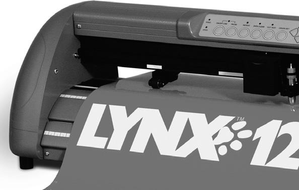
4 1.2 Front View of Lynx ( see Figure 1-1) Cutting Pad Tool Carriage Control Panel Grid Drum Paper Sensor Figure 1-1 Knife Guide Alignment Rulers Platen Pinch Rollers 1.3 Back View of Lynx ( see Figure 1-2) Lever Paper Sensor Figure 1-2 Pinch Rollers 1. Learning About Your Cutter 1-2
5 Roll Holder Support Media Roll Flanges Stand Roll Holder Figure Platen - Provides the surface for holding and supporting media during cutting. 2. Cutting Pad - Provides protection for the blade while the blade is cutting. 3. Alignment Ruler Media can be aligned with the clear guide line marks. 4. Tool Carriage This unit performs the cutting with the installed blade and pen 5. Grid Drum - Moves the media back and forth during operation. 6. Control Panel - Consists of 10 control keys and 6 LEDs. 7. Pinch Roller Presses the media against grid drum during cutting. 8. Knife Guide Easily cuts off extra media with this groove. 9. Lever - Raises or lowers the pinch rollers. Optional Items (see Figure 1-3) 1. Roll Holder Consist of two rollers to hold and feed the roll media for cutting. 2. Roll Holder Guide Bushings - Serves to keep the roll media in place when media is pulled from the roll. 3. Media Roll Flanges - Secures media roll flanges in place. 4. Roll Holder Support - Supports roll holders. 5. Stand - Supports the cutting plotter body. 1. Learning About Your Cutter 1-3
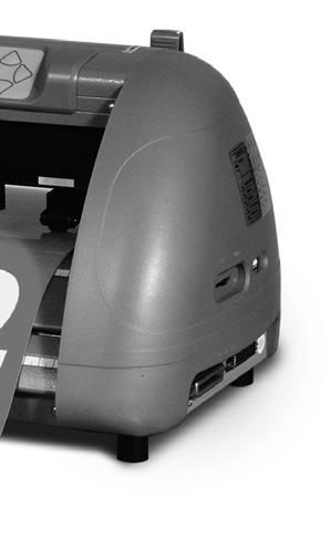
 8 9 10 1. AC Power Connector Used to insert the AC power cord. 2. Fuse Up to 3 Amps. 3. Voltage Switch The presetting is 230 voltage.")
6 This is a vinyl cutter. It is not intended to be used with windows drivers or as a printer. Signwarehouse.com does not recommend that you use these drivers. 1.4 Side View of Lynx Figure 1-4 Figure Left Hand Side (Figure 1-4) AC Power Connector Used to insert the AC power cord. 2. Fuse Up to 3 Amps. 3. Voltage Switch The presetting is 230 voltage. Please adjust to comply with your local standard. 4. Power Switch On when switches to [I]; Off when switches to [O] Right Hand Side (Figure 1-5) 5. Dip Switch label Indicates the functions of the dip switches. 6. Dip Switch - Used for various parameter settings. 7. Pen Force Control Slider Set the blade force here. 8. Universal Serial Bus Connector- Used in conjunction with Windows Printer Drivers to connect the cutting plotter to a computer through a Universal Serial Bus Cable. 9. Serial Interface Connector (RS-232C) Used to connect the cutting plotter to a computer through a serial interface cable. 10. Parallel Interface Connector (Centronics) Used to connect the cutting plotter to a computer through a parallel interface cable. 1. Learning About Your Cutter 1-4
7 2. Installation 2.1 Installation Caution 1 Make sure the power switch is off before installing the cutting plotter. Carefully handle the cutter to prevent any injuries. Caution 2 Choosing a proper place before setting up the cutting plotter Before installing your cutting plotter, select a suitable location, which meets the following conditions. The machine can be approached easily from any direction. Keep enough space for the machine, accessories and supplies. Keep the working area stable, avoiding severe vibration. Keep the temperature between 41 o -104 o F in the workshop. (High temperature may damage vinyl). Keep the relative humidity between 30% and 70% in the workshop. Protects the machine from dust and strong air current. Do not place machine in direct sunlight. Caution 3 Connecting the Power Supply Check the plug of the power cord to see if it mates with the wall outlet. If not, please contact your dealer. Insert the plug (male) into a grounded power outlet. Insert the other end (female) of power cord into the AC connector of the cutting plotter. 2. Installation 2-1
8 2.2 Stand & Flexible Media Handling System Installation (The Stand and Flexible Media Support System for Lynx S-60 is optional) Step 1 Examine supplied items in the accessory box of stand carton: 20 pieces of M6 (Alan head) screws 20 pieces of spring washers 20 pieces of washers 4 pieces black wheels (casters) 1 piece of M6 L- shape hexagon screw driver 1 piece of M6 wrench Step 2 The stand includes five parts as Figure 2-1, follow the figure number to assemble. Figure Installation 2-2
9 Step 3 Use M6 screws, washers and spring washers to assemble part 1 and 2, then use the screwdriver to tighten them; this creates an H-shaped base. Figure 2-2 and 2-3 (reverse of the H-stand) will show you the position to insert screws. Figure 2-2 Figure 2-3 Step 4 Insert the black wheels with washers into the holes on the bottom of H-shape stand as shown in Figure 2-4. Use the wrench to fasten them. Figure Installation 2-3
10 Step 5 Then connect part 3 and H-shape stand. First, position the extension of part 3 into the squares holes on H-stand. Second, insert the screws and washers into the holes besides the squares then tighten them (Figure 2-5). Figure 2-5 Step 6 Remove the cutting plotter from the carton. Position your stand under the plotter, then insert the screws into the holes on plotter s bottom. In order to make the task easier, you may need someone to help you. Figure Extension Screws holes Square holes 2. Installation 2-4
11 Step 7 Insert the roll holder support with the screws into the holes of the stand then tighten them as Figure 2-6. You can choose roll holder support s position by inserting into different holes. Step 8 Figure 2-7 Place two roll holders into the holes in the roll holder support (Figure 2-8). The nuts at the end of the roll holders will need to be unscrewed to install them. Figure Installation 2-5
12 Step 9 The complete picture will be like Figure 2-9. Figure Blade Installation Figure 2-10 is the illustrator of the blade holder. Insert a blade into the bottom of the blade holder and remove the blade by pushing the pin. Make sure that your fingers are away from the blade tip. Adjustment depth knob Pin Outward ring Figure Installation 2-6
.")
.")

13 Step 1 Install blade (Figure 2-11). Figure 2-11 Step 2 Push the blade to the bottom of the blade holder. (Figure 2-12). Figure 2-12 Step 3 Adjust the blade tip to suitable length by screwing Blade tip adjustment screw clockwise or count-clockwise. (Figure 2-13). Tips: The proper length means the blade s length is adjusted 0.1mm more than film s thickness. That is, if the thickness of film is 0.5mm, then blade s length is properly adjusted 0.6mm and it can completely cut through the film layer yet avoid penetrating the backing. Figure Installation 2-7
, then fasten the case (Figure 2-15) Step 5 Figure 2-14 Figure 2-15 Use the reversing")

14 Step 4 Insert the blade holder into tool carriage. Please note the outward ring of the holder must be placed into the grooves of carriage firmly (see Figure 2-14), then fasten the case (Figure 2-15) Step 5 Figure 2-14 Figure 2-15 Use the reversing steps to remove the blade holder. Step 6 Eject the blade. Push Blade eject pin to eject blade when the blade needs to be replaced. Caution The blade will lose its sharpness after a period of usage, and the cutting quality might be affected. Increasing the cutting force, might do the trick. However, once the blade is worn out and no longer provides a reliable cutting, you should replace with a new blade. The blade is a consumable and must be replaced as often as necessary to maintain the cutting quality. The quality of the blade affects cutting quality. So be sure to use a high quality blade to ensure good cutting results. 2. Installation 2-8
15 3. Connecting Cutting Plotters The cutting plotter communicates with a computer through a USB (Universal Serial Bus), Parallel port (Centronics) or a Serial port (RS-232C). This chapter shows you how to connect the cutting plotter to a host computer and how to set up the computer/cutting plotter interconnection.!!notice: When USB connection is enabled, both parallel port and serial port will be disabled automatically. Figure 3-1 Lever USB Port Serial Interface Connector Parallel Interface Connector 3.1 Parallel Transmission Connecting to the Parallel Port (Centronics) 1. Connect a parallel cable to the cutting plotter and the host computer (Figure 3-1) 2. Set up the output port LPT1 or LPT2 from your software package 3.2 Serial Transmission Connecting to the Serial Port (RS-232C) 1. For IBM PC, PS/2 users or compatibles, connect the RS-232C cable to the serial connector of the assigned serial port (COM1 or COM2) of your host computer. 2. Set up the communication parameters (Baud Rate and Data Bits/ Parity) to match the setting of software package, refer to chapter 3 Misc key description. 3. Connecting the Cutter 3-1
16 3.3 Transmitting the Data to Plotter There are two options to transmit the data from the computer to the cutting plotter: Option 1 - Recommended With proper interface settings, the data can be transmitted from your application software package to the cutting plotters directly. Option 2 Most cutting software packages are able to emulate HP-GL or HP-GL/2 commands, therefore, Use DOS commands like TYPE or PRINT to output your file. As long as the file is HP-GL or HP-GL/2 format, the cutting plotter can output the data precisely. For example, a file with PLT extension generated by SignLAB can be transmitted directly to the plotter at the DOS prompt, and then be cut out. Before outputting at the DOS prompt, set up a transmission protocol between your cutting plotter and computer by a DOS command, MODE. Make sure that your PC has the same communication protocol as the cutter. For example: MODE COM2: 9600, N, 8, 1, P Then, use TYPE command to output via COM2 if COM2 is the assigned output port. TYPE filename > COM2 Tip: Add the MODE command line to your system s AUTOEXEC.BAT to automatically execute MODE command every time you want to output your data at the DOS prompt via serial connection. However, values in a MODE command should comply with the related requirements of your software. Refer to DOS manual for further information. 3.4 Interfaces for Macintosh Plus/SE/II Note: Modern Macs need a USB to PIA cable to communicate with the Lynx cutter. You must have a USB to PIA cable to successfully connect your Macintosh to a Lynx cutter. 3. Connecting the Cutter 3-2


17 3.5 USB Port The USB port can only be used in conjunction with windows drivers. The windows drivers are available at ***DISCLAIMER*** This is a vinyl cutter! It is not intended to be used with windows drivers or as a printer. SignWarehouse.com does not recommend that you use these drivers. Mac USB PIA Cable Back of PC PC Parallel Cable PC Serial Cable Monitor Connection Parallel Port (LPT 1) Serial Port (COM 1) Back of laptop computer Figure Connecting the Cutter 3-3


18 4. Basic Operation 4.1 Loading the Sheet Media To load the media properly, please follow the procedures listed below: 1. Use the lever on the upper right side of the cutting plotter to raise or lower down pinch rollers. Pull the lever forward until it makes a clicking sound then the pinch rollers are raised (Figure 4-1). Lever Figure Load your media on the platen and slide it under the pinch rollers from the backside. The alignment rulers on the platen extension will help you to adjust the media precisely. Note: The media must cover the paper sensors on the platen when loading the media. At least one of the two paper sensors (Figure 4-2) should be covered. Once the media covers the sensor, the cutting plotter will size the media s width and length automatically. Front View Of Lynx Figure 4-2 Back View Of Lynx Paper Sensor 4. Basic Operation 4-1
. The cutting head will not cut outside of the pinch rollers.")
19 3. Move the pinch rollers manually to the proper position. The pinch rollers must be positioned above the grid drum. The white marks on the main beam will remind you where the grid drums are (Figure 4-3). The cutting head will not cut outside of the pinch rollers. The distance between the pinch rollers is your maximum cutting distance. White Marks Figure Push the lever backward to lower down the pinch rollers. 5. Turn on the power; the tool carriage will measure the size of the media automatically, and the plotting cutter will begin to work. Note: Move the pinch roller by applying force at the rear portion of the pinch roller support. Do not move it by holding its front rubber roller (Figure 4-4) Figure 4-4 (O) 4. Basic Operation 4-2 (X)
20 4.2 Loading the Roll Media First, put the roll media guide bushes on two roll holders (Figure 4-5) but do not lock them down. Roll Media Guide Bushes Figure 4-5 Option A (Recommended) 1) Insert the two roll holders into the roll media support set then place the roll media directly between the two roll holders (Figure 4-6). Figure 4-6 Option B (use the media flanges) 1) Insert a roll media flange at the end of each roll media and tighten the thumbscrew until the roll media is firmly gripped (Figure 4-7). Figure Basic Operation 4-3
21 2) Then put the roll media on the roll holders. Adjust the position of the roll media to ensure that media flanges are able to run in the grooves of media guide bushes (Figure 4-8). Make sure the roll is directly behind where the vinyl lines up on the front of the cutter. Then lock down roll media guide bushings. Figure 4-8 3) Loading the media on the platen. Please refer to Loading the sheet media. After loading the roll media, flatten the media on the platen and hold the front edge of the roll media firmly (Figure 4-9). Figure Basic Operation 4-4
22 4) Then turn the roll downward to make an equal tension across the media (Figure 4-10) Move the pinch rollers to the correct location and be careful that the pinch rollers are positioned above the grid drums. Push the lever backward to lower down the pinch rollers Figure ) Adjust and tighten roll media guide bushes on the roll holder to secure the roll media 6) Turn on the power switch, and then the tool carriage will size the media automatically. Then the cutting plotter is ready to work. 7) Use the reverse steps to remove the media. Make sure that the media tension is equally distributed from left to right. If the media is not tight enough against the platen it will cause tracking problems. You can also use the ROLL BASE to feed a roll media. Please adjust the position of roll base to get a good cutting result (Figure 4-11). Figure Basic Operation 4-5

23 4.3 Control Panel Figure ON/OFF LINE Key Used for communication between the cutting plotter and the host computer. When ON LINE condition, the LED above is on. Press the ON/OFF LINE LED again to turn off. 2. PAUSE Key Pressing this key once can temporarily terminate the motion of the cutter, and the ON/ OFF LINE LED flashes. Press ON/OFF LINE Key can release the paused state and resume cutting. 3. REPEAT Key- Press this button to repeat the last cutting and the REPEAT LED turns on. 4. DATA CLEAR Key - Press this key to clear the data in the buffer memory. At this moment the DATA CLEAR LED turns on. 5. CUT TEST Key - To test the set value before starting your cutting job. While doing the cut test, the CUT TEST LED is on. 6. ORIGIN SET Key This key sets a new origin point for cutting to the current tool position. 7. ARROW Key Used to move the media or the cutting carriage. 8. POWER LED Turn on the power, the POWER LED on. 9. ERROR LED When this LED is on or flashing indicates various problems or errors. To find the cause of the problems, see Chapter 5 Troubleshooting. Note: Steps 3 through 7 require the cutter to be OFFLINE. 4. Basic Operation 4-6
24 4.4 Power On Be sure not to put hands or anything else on the platen of the plotter when turning on the power. It may cause injury. Keep long hair away from the grid drum when power is on. Turn on the power switch on the left-hand side of the cutting plotter. The POWER LED will come on; the cutting plotter is ready to receive data from computer. Below is control panel lights when the different function keys are in normal conditions. Function Power Error On/Off Line on-line state Repeat Data Clear Cut Test pause state off-line state repeat data clear cut test origin set = flash = on = off 4. Basic Operation 4-7
25 4.5 ON/OFF LINE Key On - line When the machine is in the ON LINE condition, the ON/OFF LINE LED on, the cutting plotter is ready to receive data from the host computer. At this moment, only PAUSE and ON/OFF LINE keys are valid. Change the setting value of dip switch 1. Press the PAUSE key to change the setting value during cutting. 2. Press the ON/OFF LINE key to continue cutting. Terminate the cutting & clear the data in the buffer Press the ON/OFF LINE key or press the PAUSE key Then press the DATA CLEAR key Off - line When the machine is OFF Line, the ON/OFF LINE LED is turned off. At this moment, you can change the dip switch setting and do a cutting test and set the new origin as well. Pressing the key again will let the cutting plotter switch to the ON LINE condition, and will resume the suspended operation. But there might be some data loss during this interruption. 4.6 PAUSE Key The purpose of the PAUSE key is to temporarily terminate the motion of the cutter after it started cutting. At this moment, the ON/OFF LINE LED will flash; you can change the dip switch setting and the cutting force. It will resume cutting after pressing the ON/OFF LINE key to make the machine in on-line status. Note: The parameters of dip switch in effect can not be changed while the cutting has started unless pressing the PAUSE key. When press the PAUSE key, you can change the setting. 4. Basic Operation 4-8
26 4.7 Repeat Key Lynx can repeat your last cutting job at the same position by pressing the REPEAT key without setting a new origin. If you re using a thicker media, it is better to use this function to avoid damaging your blade. Procedures: 1. After cutting finishes, use the ARROW keys to move the tool carriage. Move to your desired position for repeating the cutting job, and then press the ORIGIN SET key. The ORIGIN SET LED lights, and new origin point is set. 2. Press the REPEAT key to start re-cutting job, and the REPEAT LED lights. 4.8 DATA CLEAR Key The purpose of the DATA CLEAR key is to clear the data in the buffer memory. The DATA CLEAR key only works when cutter is paused or offline. When use this function, the DATA CLEAR LED will light. 4.9 Origin Setting Use the ORIGIN SET key to set a new origin at any position in the cutting area from where the tool carriage starts to work. Please note that a new origin setting must be made under the off-line condition. Procedures: 1. After loading the media and lowering down the level, use ARROW keys to move the carriage to the desired location for a new origin. 2. Press ORIGIN SET key and the origin point is set. The ORIGIN SET LED lights. 4. Basic Operation 4-9
27 4.10 Dip Switch Setting To get a perfect cutting job, you have to choose the proper dip switch setting. The table below shows function of each dip switch. See the default setting values Figure Dip Switch Function Switch Down Switch Up Default Value SW 1-3 Offset Value (please refer to SW 1-3) mm SW-4 Media Weight Light Heavy Light Media SW-5 Quality Draft Fine Draft SW-6 Smooth Enable Disable Enable SW-7 Auto Unroll Enable Disable Enable SW-8 Media Type Roll Single Roll ON OFF Figure Adjust Offset Value The square cut out should appear as one of the follow figure: AA Lower offset value OR over-speed BB Higher offset value CC offset value If the square appears in BB or CC layout, Change the OFFSET by referring the dip switch part to adjust the value to the optimum result. OFFSET is the distance that the blade tip is displaced from the center-line of the blade. 4. Basic Operation 4-10
28 SW 1-3: OFFSET SETTING The first three dip switches represent 8 different offset values as below: SW-4: MEDIA WEIGHT (SPEED) The fourth dip switch from the left sets the upper limit for cutting speed. Heavy media has a smaller upper limit. The value of the cutting speed can be changed from the driver. Heavy media is used so the upper limit for cutting speed is 300 mm, default is 30mm/s. Light media is used so the upper limit for cutting speed is 600mm default is 330mm/s. SW-5: QUALITY There is a trade-off between Quality and Speed, the finer the cutting quality, the slower the cutting speed. Fine quality Draft quality SW-6: SMOOTH Make the curves smoother during cutting. When cutting small letters, it is recommend to disable the smoothing cut. Disable the smoothing cut. Enable the smoorhing cut. 4. Basic Operation 4-11
29 SW-7: AUTO UNROLL Unroll heavy media at least 50 cm when the next point of movement is located beyond the unrolled position. If the media type is single, this function is disabled. Disable the auto unroll Enable the auto unroll SW-8: MEDIA TYPE Set the type of the media you are using. When using a piece or single sheet of media, set it to ON ; and set it to OFF when using a roll media. Single sheet of media is using. A roll of media is using Tracking Performance In order to achieve the best tracking performance for a long plot, we recommend some important media loading procedures described as follows: 1. If the media length is less than 4 m, leave the margin of 0.5 mm~15 mm in the left and right edges of the media (see Figure 2-14). 0.5mm - 15mm 0.5mm - 15mm Pinch roller Figure 4-14 Pinch roller 4. Basic Operation 4-12
30 2. If the media length is greater than 4 m, leave at least 25 mm margin on the left and right edges of the media (see Figure 4-15). 25 mm + Pinch roller Pinch roller Figure Cutting Test In order to achieve the best cutting performance, it is necessary to set cutting conditions that match the cutting media, giving considerations to the thickness of the sheet and type of material. Lynx can perform a cutting test to determine the appropriate cutting force and offset value for your media and this can only work under the off-line condition. Once you finish the cutting test, the new origin is also set to the current tool carriage position. Procedures: 1. After sizing the media, press the ON/OFF LINE key to change the plotter status to off-line condition. 2. Then use arrow keys to move the tool carriage to the position where you like your test to proceed. 3. Press the CUT TEST key to do the cutting test. The CUT TEST LED turns on. Note: The new origin is also set at the cutting test position. 4. Basic Operation 4-13
31 4.14 Adjust Tool Force When the cutting test is completed, a square cut out appears. Peel off the square to see if it can be easily separated from the media base. If yes, the tool force is appropriate. If not, use Pen Force Control Slider on the right-hand side of the plotter to adjust the tool force. First, move the control slider to the left-most indicator mark (min. blade force), then increase the blade force gradually by moving the slider, until an optimum force is obtained. If you re still unsatisfied with the cutting results after adjusting the blade force, then you should adjust the offset value. After changing the offset value, perform the cutting test again and adjust the blade force When Completing the Cutting Job After completing the cutting, raise the sheet loading lever, then remove the material. You can also cut off the extra media with the cutter tool along the knife guide (Figure 4-16). Figure Basic Operation 4-14
32 5. Care & Basic Maintenance This chapter explains the basic maintenance (i.e. cleaning the cutting plotter) required for the cutting plotter. Except for the below mentioned, all other maintenance must be performed by a qualified service technician. 5.1 Cleaning the Cutting Plotter In order to keep the cutting plotter under good condition and best performance, you need to clean the machine properly and regularly. Cleaning Precaution! Unplug the cutting plotter before cleaning in order to prevent electrical shock. Never use solvents, abrasive cleaners or strong detergents for cleaning. They may damage the surface of the cutting plotter and the moving parts. Recommended Methods: Gently wipe the cutting plotter surface with a lint-free cloth. If necessary, clean with a damp cloth or an alcohol-immersed cloth. Wipe with water to rinse off any residue and dry with a soft, lint-free cloth. Wipe all dust and dirt from the tool carriage rails. Use a vacuum cleaner to empty any accumulated dirt and media residue beneath the pinch roller housing. Clean the platen, paper sensors and pinch rollers with a damp cloth or an alcohol-immersed cloth, and dry with a soft, lint-free cloth. Wipe dust and dirt from the stand. 5. Care & Basic Maintenance 5-1
33 5.2 Cleaning the Grid Drum 1. Turn off the cutting plotter, and move the tool carriage away from the area needed to be cleaned. 2. Raise the pinch rollers and move them away from the grid drum for cleaning. 3. Use a bristle brush (a toothbrush is acceptable) to remove dust from the drum surface. Rotate the drum manually while cleaning. Refer to Figure 5-1 Figure Cleaning the Pinch Rollers 1. If the pinch rollers need a thorough cleaning, use a lint-free cloth or cotton swab to wipe away the accumulated dust from the rubber portion of the pinch rollers. To prevent the pinch rollers from rotating while cleaning, use finger to hold the pinch rollers still. 2. To remove the embedded or persistent dust, use the lint-free cloth or cotton swab moistened with rubbing alcohol. 5. Care & Basic Maintenance 5-2
34 6. Trouble Shooting This chapter helps you to correct some common problems you may come across. Prior to getting into the details of this chapter, please be sure that your application environment is compatible with the cutting plotter. Note: Before having your cutting plotter serviced, please make certain that the malfunction is in your cutting plotter, not the result of an interface problem or a malfunction in your computer or a software problem. Why is the cutting plotter not functioning? 6.1 If the cutter does not operate? If your Lynx doesn t run, please check the following items first: Is the AC power cord plugged in properly? Is the AC power cord connected to the power connector properly? Is the power on? Solutions: If the POWER LED lights on, the cutting plotter should be in a normal condition. Switch off the cutting plotter and turn it on again to see if the problem still exists. If the POWER LED doesn t light, contact the technician from your dealer. 6. Troubleshooting 6-1
35 6.2 Light Indicators Certain problems are identified by the control panel lights. If your cutting plotter stops operating or the lights are on or flashing unexpectedly, check the following descriptions of panel light patterns and the corrective actions you should take. 6.3 Warning Indicators When the ERROR LED flashes (as show below), take the necessary action according to respective instruction below. If the problems are solved, the ERROR LED will turn off automatically. Press ON/OFF LINE key once can also turn off the ERROR LED. Warning Indicators Error On/Off Line 1 Graph was clipped Repeat Data Clear Cut Test 2 HPGL/2 command error 3 Lever up or no media 4 Cannot repeat 5 Communication error 6 Width sensor error = flash = on = off Warning 1 The graph is clipped This condition indicates that the cutting graph exceeds the cutting limit. You can solve the problem by 1. Reload the larger media 2. Move the pinch roller to have larger cutting width 3. Re-scale the plot to a smaller size. Then send the cutting job again from your computer. Warning 2 HPGL/2 command error If your cutting plotter can not recognize the commands from your computer, please check that the commands applied to your cutting plotter are used properly. Be sure it is the HP-GL/2 or HPGL command. Then send the same cutting job to the plotter again, if it shows the same result, please contact your dealer. 6. Troubleshooting 6-2
36 Warning 3 Lever up or no media Check the lever position and be sure to put the media in the cutting plotter before cutting. Warning 4 Cannot repeat cutting This condition happens for two reasons: the buffer holds no data or the buffer is full. For the former condition, please send a new graph from the computer; for the latter condition, please repeat the same cutting job from the computer. In both conditions, press ON/OFF LINE key to clear the message. Warning 5 Communication error Check if the connection cable is connected to the cutting plotter and computer properly. If yes, then check if the interface setting is correct, make sure your PC has the same communication protocol as the cutter 9600 bps, no parity, 8 bits, 1 stop bit, and none for hand shaking. If you have done the above, try the communication between your cutting plotter and computer again. Press ON/OFF Line key to force the cutter to on line condition. Warning 6 Width sensor error Check if the pinch rollers are positioned above the grid drum and reload the media again. 6. Troubleshooting 6-3
37 6.4 Error Indicators If mechanical problems or failure during operations happen, the ERROR LED will turn on. Please follow the instruction below to solve the problem. If the plotter still cannot work, please inform your dealer of these types of error indicators or have your plotter serviced. Error Indicators Error On/Off Line 1 Sram error Repeat Data Clear Cut Test 2 Dram error 3 Check media, drum, or X motor 4 Check media or Y motor = flash = on = off Error 1 and 2. At this moment, please contact your dealer. Error 3. Check media drum, or X motor This message indicates that there might be a problem on the X axis. Check if the drum is working well and if the media is well loaded. Correct the problem and re-power on to reboot system. Error 4. Check media, or Y motor This message indicates that there might be an obstruction to carriage relating to a problem on the Y axis. Correct the problem and re-power on to reboot system. 6. Troubleshooting 6-4
38 6.5 Cutting Quality Problems Is the blade installed correctly and the blade holder fastened securely? Yes No Is the blade dull or chipped? Refer to the Blade Installation. Yes No Replace with a new blade. Is tool force set up properly? Yes Is the tool offset set up properly? No Adjust the tool force to obtain an optimum blade force. Refer to 2.13 CUTTING TEST Yes Is there any dirt adhered to the blade? No Adjust the blade offset to obtain an optimum value. Yes No Remove the blade and blade holder and clean them. Please contact your dealer for technician support. 6. Troubleshooting 6-5
39 Quick Menu 1. Power ON (the POWER LED lights on) 2. Place the media and pull the lever to lower down the pinch rollers (make sure the pinch rollers are positioned above the grid drums, that is, within the white marks). 3. The cutting plotter will size the media automatically according to the setting of the dip switch on the right side of the cutter (usually the presetting is ROLL media type). 4. Off-line condition- Plotter is not ready to receive data from computer. Press ON/OFF LINE key, the LED above is off. 5. On-line condition- Plotter is ready to receive data from computer. Press ON/OFF LINE, the LED above lights. 6. Change the setting value during cutting - Press PAUSE key, the LED above flashes. To continue cutting press ON/OFF LINE. 7. Terminate the cutting and clear the data in the buffer. - Press ON/OFF LINE or PAUSE and then press DATA CLEAR. A. Quick Menu I
40 Important Information Thanks for purchasing a Lynx cutting plotter. To optimize the performance of your Lynx, please take the time to read through the user manual completely and follow up the correct operation procedure. Hope you will enjoy using your cutting plotter. SAFETY PRECAUTIONS! Caution For safety concern, please always hold the cutter firmly from the bottom when moving it. Do not move the cutter by clasping the depression area on both sides. O (Correct) Hold from the bottom X (Incorrect) Hold the depression area Do not shake or drop the blade holder, blade tip can fly out. During operation, do not touch any of the moving parts of this machine (such as the carriage). Also be careful that clothing and hair do not become caught. Always connect the power cable to a grounded outlet. Always use the accessory power cable that is provided. Do not wire the power cable so that it becomes bent or caught between objects. Do not connect the power cable to branching outlet to which other machines are also connected, or use an extension cable. There is danger of overheating and of mis-operation of the machine. Keep the tools out of the reach of children. Always position the pinch rollers beneath the white marks. A. Important Information II
41 About the Tool OFFSET is the distance that the blade tip is displaced from the center-line of the blade. Blade Central line Blade tip Offset Protrusion Length of the Blade Protrusion length of the blade Thickness of the film (t1) Thickness of the base paper (t2) Length of protrusion = t1 + t 2/ 2, but for your convenience you may just make it about 0.3~ 0.5 mm beyond the blade holder tip. A. About the Tool III

42 Lynx Series Optional Accessories The following items are available for Lynx series: Item Part No. Description US Price Vinyl Express Blade (Fits all Vinyl Express cutters) PLTB-ROLAND US $14.00 PLTB-ROLAND US $11.00 PLTB-ROLAND US $11.00 Item Part No. Description US Price Blade Holder P-BK02019A 1 oz US $75.00 Item Part No. Description US Price GRC-61/60/Lynx Cutting Pad 24 PLTA-ZZ700B-61 1 oz US $12.00 GRC-Lynx Cutting Pad 12 PLTA-ZZ800B-S30 1 oz US $10.00 A. Optional Accessories IV
43 Equipment Specification Specification: Lynx S-60, S-30 Model Name/ No. LYNX S cutter LYNX S cutter Operational Method Roller-Type Max. Cutting Width 590mm (23.23in) 280mm (11.02in) Max. Media Loading Width 719mm (28.3in) 459mm (18.07in) Min. Media Loading Width 50 mm Acceptable Material Thickness 0.8mm (0.03 in) Number of Pinch Rollers 2 Drive DC Servo Control Cutting Force 0~300 g Max. Cutting Speed Up to 600 mm/sec (23.62 ips) Offset 0~1.0 mm Mechanical Resolution mm Software Resolution mm Distance Accuracy mm or 0.1 % of move, whichever is greater Repeatability mm up to 3 meters (*certified media) Buffer Size 4 MB Interfaces Parallel (Centronics) & Serial (RS-232C) Commands HP-GL, HP-GL/2 Configurable Origin Yes Vector Look Ahead Yes Curve & Arc Smoothing Yes Test Cut Possibility Yes Repeat Function Yes Control Panel 10 Control Keys, 6 LED Dimension (HxWxD) mm (HxWxD) in 220 x 879 x x x lb 220 x 619 x x x in Net Weight (kg) 13 kg/ 28.6 lb 10.2 kg/ 22.4 lb Power Supply 115V/230V (manual switch) Environment Temperature 0 o C~55 o C / 32 o F~131 o F (operating) -40 o C~75 o F~167 o F (storage) Environment Humidity 30% ~ 70% relative humidity (operating) *This specification is subject to change without prior notice. A. Equipment Specifi cation V
EXPERT 24 CUTTING PLOTTER User Manual
 EXPERT 24 CUTTING PLOTTER User Manual ` Great Computer Corporation NOTICE GCC reserves the right to modify the information contained in this user manual at any time without prior notice; un-authorised
EXPERT 24 CUTTING PLOTTER User Manual
 EXPERT 24 CUTTING PLOTTER User Manual ` Great Computer Corporation V.12 2014 Jun. NOTICE GCC reserves the right to modify the information contained in this user manual at any time without prior notice;
Jaguar IV Series User Manual
 Jaguar IV Series User Manual http://www.gccworld.com V.2.4 Apr. 08 NOTICE GCC reserves the right to modify the information contained in this user manual at any time without prior notice; un-authorized
User Manual. https://www.signwarehouse.com/blog-support/ NOTICE
 User Manual https://www.signwarehouse.com/blog-support/ NOTICE SignWarehouse Inc. reserves the right to modify the information contained in this user manual at any time without prior notice; un-authorized
EXPERT II Series User Manual
 EXPERT II Series User Manual ` http://www.gccworld.com V.7 2017 Jun. NOTICE GCC reserves the right to modify the information contained in this user manual at any time without prior notice; un-authorized
MONARCH 9416 XL QUICK REFERENCE
 MONARCH 9416 XL QUICK REFERENCE This Quick Reference contains ribbon loading, supply loading, and general care, maintenance, and troubleshooting procedures for the 9416 XL Thermal Direct and 9416 XL Thermal
EXPERT 52 LX CUTTING PLOTTER User Manual
 EXPERT 52 LX CUTTING PLOTTER User Manual ` Great Computer Corporation V.6 2014 Mar. NOTICE GCC reserves the right to modify the information contained in this user manual at any time without prior notice;
USER MANUAL. Sign Cutting Plotter VC-600 VC-1300 VC Read This Manual Before Using The Plotter.
 USER MANUAL Sign Cutting Plotter VC-600 VC-1300 VC-1800 Read This Manual Before Using The Plotter. Rev No. Trademark Mentioned in this Manual MUTOH, ValueCut, VC-600, VC-1300, VC-1800, ValueJet are registered
Expert Pro Series User Manual
 Expert Pro Series User Manual http://www.gccworld.com V.16 2015 Jul NOTICE GCC reserves the right to modify the information contained in this user manual at any time without prior notice; un-authorized
User Manual. https://www.signwarehouse.com/blog-support/ NOTICE
 User Manual https://www.signwarehouse.com/blog-support/ NOTICE SignWarehouse Inc. reserves the right to modify the information contained in this user manual at any time without prior notice; un-authorized
Removal and Installation8
 8 Screw Types 8-4 Top Cover Assembly 8-5 Left Hand Cover 8-6 Right Hand Cover 8-10 Front Panel Assembly 8-14 Left Rear Cover 8-15 Right Rear Cover 8-16 Extension Cover (60" Model only) 8-17 Media Lever
ASTRO UW-1C and RW-1C LABEL PRINTER UNWINDER & WINDER
 ASTRO UW-1C and RW-1C LABEL PRINTER UNWINDER & WINDER OPERATOR MANUAL ASTRO MACHINE CORP. 630 Lively Blvd. Elk Grove Village, IL 60007 Phone: (847) 364-6363 Fax: (847) 364-9898 www.astromachine.com SAFETY
CANADIAN D.O.C. WARNING
 Each product and program carries a respective written warranty, the only warranty on which the customer can rely. Avery Dennison Corp. reserves the right to make changes in the product, the programs, and
TT230SM THERMAL TRANSFER PRINTER USER S MANUAL
 TT230SM THERMAL TRANSFER PRINTER USER S MANUAL Operations Overview Unpacking and Inspection This printer has been specially packaged to withstand damage during shipping. Please carefully inspect the packaging
FRESHMARX 9417 QUICK REFERENCE
 FRESHMARX 9417 QUICK REFERENCE For more detailed information, refer to the Operator s Handbook available on our Web site (www.monarch.com). Review the printer safety information in the Safety Sheet provided
User's Manual. Metapace L-22D. Label Printer Rev. 1.00
 User's Manual Metapace L-22D Label Printer Rev. 1.00 Table of Contents MANUAL INFORMATION & USAGE PRECAUTIONS... 3 1. CONTENT CONFIRMATION... 6 2. PRODUCT PARTS... 7 3. INSTALLATION & USAGE... 9 3-1 POWER
LabelMax SP2 User Manual
 LabelMax SP2 User Manual 1 GENERAL... 3 1.1 COPYRIGHT DECLARATION... 3 1.2 COMPLIANCES... 3 1.3 INTRODUCTION... 3 2 GETTING STARTED... 4 2.1 UNPACKING AND INSPECTION... 4 2.2 EQUIPMENT CHECKLIST... 4 2.3
Copyright Information: Firmware (Software) Agreement:
 Agreement:") Maintenance Manual Copyright Information: CG Triumvirate is a trademark of Agfa Corporation. CG Times based upon Times New Roman under license from the Monotype Corporation. Windows is a registered trademark
Maintenance Manual Copyright Information: CG Triumvirate is a trademark of Agfa Corporation. CG Times based upon Times New Roman under license from the Monotype Corporation. Windows is a registered trademark
MX-8000 User Manual MX Rev
 MX-8000 Rev. 070202 Greeting Thank you for purchasing PAITEC USA products. This manual is prepared to provide guidelines on how to properly operate and maintain MX-8000. Copyright Any of the contents should
CANADIAN D.O.C. WARNING
 Each product and program carries a respective written warranty, the only warranty on which the customer can rely. Avery Dennison Corp. reserves the right to make changes in the product, the programs, and
Quick Start Guide Ioline StudioJet
 Quick Start Guide Ioline StudioJet User Notice Trademarks Ioline StudioJet is a trademark of Ioline Corporation. HP is a trademark of the Hewlett-Packard Company. Other product names, logos, designs, titles,
FC7000 Quick Manual E-1 FC7000-UM-8M2
 FC7000 Quick Manual FC7000-UM-8M2 Thank you for choosing an FC7000 Series cutting plotter. To ensure the safe and correct use of your cutting plotter and to fully understand and make optimum use of its
User Manual. Binocular Stereo Microscope. MicroscopeNet.com
 User Manual Binocular Stereo Microscope Model K2213 Series MicroscopeNet.com Table of Contents i. Caution... 1 ii. Care and Maintenance... 1 1. Components Illustration... 2 2. Installation... 3 3. Operation...
User s Manual M EN
 User s Manual Before Use.................................. 2 Unpacking.................................. 3 Part Names and Functions................... 4 Setup....................................... 6 Installing/Replacing
Auto-Cutter (JM98901) User's Manual
 User's Manual") Auto-Cutter (JM98901) User's Manual -2- Contents Notice 3 SAFETY SIGNS that must be strictly observed! 5 1. Function 7 2. Main specifications of auto-cutter 7 3. Checking items inside the accessory box
Auto-Cutter (JM98901) User's Manual -2- Contents Notice 3 SAFETY SIGNS that must be strictly observed! 5 1. Function 7 2. Main specifications of auto-cutter 7 3. Checking items inside the accessory box
Users Manual STP-103II. Thermal Printer Rev
 Users Manual STP-103II Thermal Printer Rev. 1.00 http://www.bixolon.com Safety Precautions The instructions shown below must be followed to prevent possible danger or damage by using the product incorrectly.
 1 Contents Welcome... 3 Cutter Parts... 4 Front View... 4 Detail of Carriage Arm... 5 Right Side View... 6 Left Side View... 7 Back View... 8 Detail of Pinch Roller (Back View)... 9 Control Panel... 10
User Manual. Trinocular Stereo Microscope
 User Manual Trinocular Stereo Microscope Model V434 XV434 Series MicroscopeNet.com Table of Contents i. Caution.. 1 ii. Care and Maintenance... 2 1. Component Illustration... 3 2. Installation 4 3. Operation....6
Table of Contents. Unpacking and Inspection Setup Loading the Media Mount the Printer on the Wall... 16
 WPL25/WHC25 Table of Contents Unpacking and Inspection... 1 Setup... 5 Loading the Media... 6 Mount the Printer on the Wall... 16 LED and Button Functions... 17 Troubleshooting... 18 Unpacking and Inspection
Vinyl Express Cougar 24
 Vinyl Express Cougar 24 Owner s Manual ValueCut 24 Table of contents 1. Safety precautions...1 2. Standard accessories...3 3. Install machine...5 3.1 Installation and connection......5 3.2 Install cutting
1. Review the printer safety information in the Regulatory Compliance document provided with your printer.
 QUICK REFERENCE This Quick Reference contains supply loading information and general care and maintenance procedures for the Monarch Pathfinder Ultra Platinum 6039 printer. For more detailed information,
EPSON ActionLaser Read This First. eepa POLLUTION PREVENTER
 EPSON ActionLaser 1400 Read This First eepa POLLUTION PREVENTER This booklet is to help you set up your printer and begin printing quickly. It also gives you instructions for routine maintenance. If you
Specification PM SER IES T h erm al B a rcodep rinters
 Specification PM SER IES T h erm al B a rcodep rinters P M 3120 Proficient in Commercial POS Receipt printers 1. Introduction...2 1.1 Safety Warning...2 1.2 Note...2 2. General Information...3 2.1 Introduction...3
QUICK REFERENCE. Getting Started
 QUICK REFERENCE This Quick Reference contains supply loading information and care and maintenance procedures for the Monarch Pathfinder Ultra Silver 6032 printer. For more detailed information, refer to
Stereo Turntable System
 3-866-873-15(1) Stereo Turntable System Operating Instructions OWNER S RECORD The model and serial numbers are located at the rear. Record the serial number in the space provided below. Refer to them whenever
VJ-1604 INSTALLATION MANUAL
 Please read this manual before using Thank you for purchasing a MUTOH product. This manual explains the steps for unpacking, mounting and basic installation before using the MUTOH Full-color inkjet printer
2 1.1 Safety using methods Definition of warning symbols Standard accessories Installation...
 Table of Contents 1 Satety precautions... 2 1.1 Safety using methods...2 1.2 Definition of warning symbols...2 2 Standard accessories......6 3 Installation... 7 3.2 Leg frame... 7 3.3 Installation and
KM-4800w. Installation Guide
 KM-4800w Installation Guide TABLE OF CONTENTS page 1 Installation Requirements 2 2 Unpacking 3 2. 1 Unpacking 3 2. 2 Confirmation of Accessories 5 3 Leveling the Machine 7 4 Setup of the Roll Deck 9 5
QUICK REFERENCE. Connecting the Cables
 QUICK REFERENCE This Quick Reference contains supply loading and general care and maintenance procedures for the Monarch 9860 printer. For more detailed information, refer to the Operator s Handbook available
9-pin dot matrix printer
 9-pin dot matrix printer All rights reserved. No part of this publication may be reproduced, stored in a retrieval system, or transmitted in any form or by any means, electronic, mechanical, photocopying,
Nexa PX700IIS Thermal Receipt Printer. User Manual. P a g e 1
 Nexa PX700IIS Thermal Receipt Printer User Manual P a g e 1 Table of Contents Safety Notice... 3 Available Functions... 3 Main Features... 4 Technical Specifications... 4 Unpacking the Printer... 5 Connection
Lexmark X203n and X204n Series. Maintenance Guide
 Lexmark X203n and X204n Series Maintenance Guide February 2011 www.lexmark.com Contents...3 Cleaning the exterior of the printer...3 Cleaning the scanner glass...4 Cleaning the ADF separator rollers...5
Xerox 8264E Color Wide Format Printer 100kg Unwinder / Winder
 November 2009 70P3070 Xerox 8264E Color Wide Format Printer 00kg Unwinder / Winder 2009 Xerox Corporation. All rights reserved. Xerox, the sphere of connectivity design, and Xerox 8264E Color Wide Format
K Service Source. StyleWriter
 K Service Source StyleWriter K Service Source Basics StyleWriter Basics Introduction - 1 Introduction The StyleWriter is a serial bubble jet ink-on-demand printer. The StyleWriter prints up to 1/3 page
THERMAL PRINTER PR-TB4
 THERMAL PRINTER PR-TB4 Hardware Manual Federal Communications Commission Radio Frequency Interference Statement This device complies with Part 15 of the FCC Rules. Operation is subject to the following
VJ-1304 INSTALLATION MANUAL
 Please read this manual before using Thank you for purchasing a MUTOH product. This manual explains the steps for unpacking, mounting and basic installation before using the MUTOH Full-color inkjet printer
MUTOH EUROPE N.V. Tel.:32-(0) Fax:32-(0)
 Fax:32-(0)") MUTOH INDUSTRIES LTD. Tel.:8-(0)-570-00 Fax:8-(0)-570-00 E-mail:ibd@mutoh.co.jp http://www.mutoh.co.jp MUTOH AMERICA INC. Tel.:-80-968-777 Fax:-80-968-7990 E-mail:sales@mutoh.com http://www.mutoh.com MUTOH
MUTOH INDUSTRIES LTD. Tel.:8-(0)-570-00 Fax:8-(0)-570-00 E-mail:ibd@mutoh.co.jp http://www.mutoh.co.jp MUTOH AMERICA INC. Tel.:-80-968-777 Fax:-80-968-7990 E-mail:sales@mutoh.com http://www.mutoh.com MUTOH
VJ-1614 INSTALLATION MANUAL
 VJ-6 INSTALLATION MANUAL Please read this manual before using Thank you for purchasing a MUTOH product. This manual explains the steps for unpacking, mounting and basic installation before using the MUTOH
User Manual. Binocular Zoom Stereo Microscope with Boom Stand. MicroscopeNet.com
 User Manual Binocular Stereo Microscope with Boom Stand Model W42C1 Series MicroscopeNet.com Table of Contents i. Caution.. 1 ii. Care and Maintenance... 1 1. Component Illustration... 2 2. Installation...3
Vinyl Express Qe60+ Signwarehouse.com. USER S MANUAL MANUAL NO. VEXQe6+-UM-151 CUTTING PLOTTER
 Vinyl Express Qe60+ CUTTING PLOTTER USER S MANUAL MANUAL NO. VEXQe6+-UM-151 Signwarehouse.com PREFACE Thank you for choosing a Signwarehouse Vinyl Express Series cutting plotter. The Vinyl Express cutting
X940e, X945e. Maintenance Guide
 X940e, X945e Maintenance Guide July 2010 www.lexmark.com Contents...3 Storing supplies...3 Checking the status of supplies...3 Checking the status of supplies from the control panel... 3 Printing a menu
Removal and Installation 8
 Removal and Installation 8 8 Introduction 8-2 Service Calibration Guide to Removal and Installation 8-4 Window 8-8 Covers and Trims 8-12 Rear Tray 8-31 Rear Cover 8-32 Media Lever 8-33 Media Lever Position
ScanPartner 600C Image Scanner. User s Manual
 ScanPartner 600C Image Scanner User s Manual Version 1.0 (Doc. No. 250-0062-0) Table of Contents 1. INTRODUCTION 3-4 2. INSTALLATION AND CONNECTIONS. 5-13 2.1 Shipping Bracket 5 2.1.1 Removing the Shipping
Mini Cutting Plotter. NODE 101/ Cutok USER S MANUAL
 Mini Cutting Plotter NODE 101/ Cutok USER S MANUAL Thank you for purchasing cutter NODE 101 / Cutok. It can be used for cutting vinyl, heavy-cardstock, paper and sticker film as well as pen plotting. Please
Ioline 300/350HF System
 Quick Start Guide Ioline 300/350HF System User Notice Trademarks Ioline is a trademark of Ioline Corporation. Other product names, logos, designs, titles, words or phrases mentioned within this publication
Assembly and Setup Manual
 M-12 Series Copyboard / C-12 Series Captureboard Assembly and Setup Manual This is the installation and assembly manual for the M-12 series Copyboard and C-12 series Captureboard. (The copyboard and/or
Be sure to read the attached "TO ENSURE SAFE AND CORRECT USE" prior to use. Otherwise, it may cause an unexpected accident or fire.
 CE6000 SERIES CUTTING PLOTTER SETUP MANUAL MANUAL NO.CE6000-UM-8M4 Preface Thank you for choosing this product. Carefully keep this manual in a handy location for quick reference as necessity prior to
C935 Series. Maintenance Guide
 C935 Series Maintenance Guide April 2007 www.lexmark.com Contents...3 Cleaning the exterior of the printer...3 Storing supplies...3 Conserving supplies...3 Checking the status of supplies...4 Checking
M7 SERIES Thermal Printer Service Manual 4. PART LIST. 4.1 Main Printer Assemblies
 4. PART LIST 4.1 Main Printer Assemblies 31 No. Part No. Description Remark Spare Requirement 1 120732 Electronics cover 1 pc 2 N/A Mainframe 1 pc 3 120733 Cover, front 1 pc 4 120734 Top right side cover
Domino One-Pocket Currency Discriminator
 Domino One-Pocket Currency Discriminator H This manual contains important information on safety measures and operational features of the Kolibri Domino 1-pocket currency discriminator. Please read it carefully
S-100X / S-200X Snow Machine User Manual
 S-100X / S-200X Snow Machine User Manual English Français Deutsch 中文 2014 Antari Lighting and Effects Ltd. 1 2 User Manual Antari S-100X & S-200X Snow Machine Introduction Thank you for choosing an ANTARI
HD Mini IR Waterproof Bullet Network Camera. Quick Start Guide. Version 1.0.0
 HD Mini IR Waterproof Bullet Network Camera Quick Start Guide Version 1.0.0 Welcome Thank you for purchasing our Network camera! This user s manual is designed to be a reference tool for your system. Please
OV1000 Part No OV1000 HEIGHT ADJUSTABLE TABLE USER GUIDE
 OV1000 Part No. 23624 OV1000 HEIGHT ADJUSTABLE TABLE USER GUIDE PRODUCT OVERVIEW User Guide: OV1000 OV1000 HEIGHT ADJUSTABLE TABLE A healthier work environment starts with the option to sit or stand throughout
Installation Manual. 65 Interactive LED/LCD. Model: HILF65101 (64.56 )
") Installation Manual 65 (64.56 ) Model: HILF65101 65 Interactive LED/LCD QUICK SETUP GUIDE For further information, see the user manual. Please contact directly if you have questions on the use of the touch
Installation Manual 65 (64.56 ) Model: HILF65101 65 Interactive LED/LCD QUICK SETUP GUIDE For further information, see the user manual. Please contact directly if you have questions on the use of the touch
EQUIPMENT OPERATION MANUAL
 EQUIPMENT OPERATION MANUAL Loctite 200, 300, and 400 Series Benchtop Robots Book 1 of 4: A Company FOR SAFE USE Safety Notes Read the following Warnings and Cautions thoroughly for the safe use of the
VJ-1618 INSTALLATION MANUAL
 Please read this manual before using Thank you for purchasing a MUTOH product. This manual explains the steps for unpacking, mounting and basic installation before using the MUTOH Full-color inkjet printer
CE5000 Series USER S MANUAL MANUAL NO. CE5000-UM-153
 CE5000 Series CUTTING PLOTTER USER S MANUAL MANUAL NO. CE5000-UM-153 PREFACE Thank you for choosing a Graphtec CE5000 Series cutting plotter. The CE5000-60/120 cutting plotters employ a digital servo
EPSON. ActionLaser Read This First
 EPSON ActionLaser 1600 Read This First This booklet is to help you set up your printer and begin printing quickly. It also gives you instructions for routine maintenance. If you need detailed information
Operation Manual WARNING. Be sure to read this Operation Manual before use. Universal Space Amusement Equipment Ltd.
 WARNING Be sure to read this Operation Manual before use. Universal Space Amusement Equipment Ltd. CONTENTS 1. The company..2 2. Specifications.. 3 3. Package Contents..5 4. Installation, Fix and Transport..6
Auto-Cutter. User s Manual. (For CL-S52X/53X/62X/63X, CL-S400DT,CL-E720/E730/E720DT)
") Auto-Cutter User s Manual (For CL-S52X/53X/62X/63X, CL-S400DT,CL-E720/E730/E720DT) Contents Notice... 3 SAFETY SIGNS that must be strictly observed!... 4 1. Function... 6 2. Main specifications of auto-cutter...
Auto-Cutter User s Manual (For CL-S52X/53X/62X/63X, CL-S400DT,CL-E720/E730/E720DT) Contents Notice... 3 SAFETY SIGNS that must be strictly observed!... 4 1. Function... 6 2. Main specifications of auto-cutter...
PS805 Thermal Receipt Printer. User Manual. Safety Notice: Main Features:
 Thermal Receipt Printer Safety Notice: * Read this manual before operate and/or connect the printer. * Don't touch the printer head with hard objects. * Don't touch the cutter blade. * Don't bend the power
DOT MATRIX PRINTER SP6000 SERIES
 DOT MATRIX PRINTER SP6000 SERIES Hardware Manual < Approval: CEL > Trademark acknowledgments SP6000 : Star Micronics Co., Ltd. Notice All rights reserved. Reproduction of any part of this manual in any
IOLINE SUMMIT 2200 MARKER PLOTTER GUIDE TO OPERATIONS
 IOLINE SUMMIT 2200 MARKER PLOTTER GUIDE TO OPERATIONS Ioline Corporation Kirkland, Washington IOLINE Summit 2200 Marker Plotter This is the first edition of the Summit 2200 Marker Plotter Guide to Operations.
QUICK REFERENCE. RFID Overview
 QUICK REFERENCE This Quick Reference contains supply loading and general maintenance procedures for the Monarch 9855 RFID printer. Additional RFID documents are available on the Monarch Printer s Documentation
Cub CB-724e / CB-534e
 Cub CB-724e / CB-534e THERMAL TRANSFER / DIRECT THERMAL BAR CODE PRINTER USER S MANUAL Contents 1. Introduction...1 2. Getting Started...1 2.1 Unpacking and Inspection...1 2.2 Equipment Checklist...1 2.3
VnM 2 SignMaker User Manual Version Updated: 07/2010
 VnM 2 SignMaker User Manual Version 2.0 Updated: 07/200 Introduction Thank you for purchasing the VnM2 SignMaker. Let your imagination run wild with the VnM2 by creating a variety of signs and labels
INSEBO2IRF 2.1MP 1080P IP Eyeball Camera with IR
 INSEBO2IRF 2.1MP 1080P IP Eyeball Camera with IR Quick Start Guide Version 1.0.0 Welcome Thank you for purchasing our Network camera! This user s manual is designed to be a reference tool for your system.
Operator s Handbook. Monarch FreshMarx 9417 Food Freshness System. TC9417OH Rev. AE 1/ Avery Dennison Corp. All rights reserved.
 Operator s Handbook Monarch FreshMarx 9417 Food Freshness System TC9417OH Rev. AE 1/2015 2013 Avery Dennison Corp. All rights reserved. Each product and program carries a respective written warranty, the
Model No. ET-JPF200BE
 Operating Instructions Floor Stand Kit Commercial Use Model No. ET-JPF200BE ET-JPF200WE ENGLISH FRANÇAIS ESPAÑOL DEUTSCH ITALIANO * The above illustration is of this product mounted to an optional projector.
RJ-2030/2050/2140/2150
 Printed in China LBF85400 Package Contents Check that the package contains the following before using your printer: RJ-030/050/40/50 Quick Setup Guide English Printer Rechargeable Li-ion Battery Belt Clip
X925. Maintenance Guide
 X925 Maintenance Guide April 2011 www.lexmark.com Contents...3 Cleaning the exterior of the printer...3 Cleaning the scanner glass...3 Cleaning the ADF parts...4 Cleaning the printhead lenses...5 Storing
Airport Bag Tag Printers. Level 1 Repair Program. Unimark ET6000 Unimark 8500
 Level 1 Repair Program Unimark ET6000 Unimark 8500 Version: 2.2 Date: February 15, 2005 Owner: Business Support Author: Jack Michko Table of Contents Table of Contents Table of Contents... ii Unimark ET6000
fi-4120c Image Scanner
 P3PC-E007-01EN fi-4120c Image Scanner Cleaning and Maintenance 5 DAILY CARE This chapter describes how to clean the scanner. WARNING When cleaning the scanner, turn off the power, and unplug the AC cable
M40 Microscope User s Manual
 M40 Microscope User s Manual for M40 and M40RT Microscope Components: Trinocular Port Eyepieces Beam Splitter Field Diaphragm Adjustment Aperture Diaphragm Adjustment Filter Slots Analyzer Polarizer Hex
AstroJet TM M2 Quick Start Guide
 AstroJet TM M2 Quick Start Guide Step 1 Remove Printer and Accessories from packaging. Place Printer on a flat, even surface. Step 2 Remove Service Station Transport Tab 1. Open Top Cover. 2. Open Print
Vacuum Tubes Power Supply Unit. for WA7 and WA7d Fireflies. Owner s Manual. Please review this manual before operating your WOO AUDIO product.
 WOO AUDIO WA7tp Vacuum Tubes Power Supply Unit for WA7 and WA7d Fireflies Owner s Manual Please review this manual before operating your WOO AUDIO product. Inc. All rights reserved. www.wooaudio.com Rev
Disconnect the battery to ensure there will be no shorted wires during the installation procedure.
 The round-style headunit receiver radio features Bluetooth technology allowing music to wirelessly stream from your compatible Bluetooth-enabled device. Control the audio from a distance -- all from your
HD Mini IR Waterproof Fixed Network Camera. Quick Start Guide. Version 1.2.0
 HD Mini IR Waterproof Fixed Network Camera Quick Start Guide Version 1.2.0 Welcome Thank you for purchasing our Network camera! This user s manual is designed to be a reference tool for your system. Please
MODEL : LK-B24 LABEL PRINTER
 J. STEPHEN Lab., Ltd. 28-6, Gajangsaneopdong-ro, Osan-si, Gyeonggi-do,18103, Republic of Korea TEL : +82-31-8077-5000 FAX : +82-31-459-8880 www.miniprinter.com MODEL : LK-B24 LABEL PRINTER B24 Rev.E 09/17
Assembly and Setup Manual
 M-11 Series Copyboard/C-11 Series Captureboard Assembly and Setup Manual This is the installation and assembly manual for the M-11 series/c-11 series. To the Customer Specialized techniques are required
ATOM. Instruction Manual. Head. from software version: 8.
 Instruction Manual from software version: 8 ATOM Head support@glp.de www.glp.de Contents 1 Description of Device... 3 2 Safety Instructions... 4 3 Mounting... 6 3.1 Operating on the Floor (Upright)...
Richter Optica. Instructions for Model: MDS2 Middle School Microscope
 Richter Optica info@richter-optica.com Instructions for Model: MDS2 Middle School Microscope Eyepiece 360 Rotatable Head Revolving Nosepiece Carrying Handle Objectives Rack Stop Stage Stage Clips Disc
Zebra XiII-Series Printer Quick Reference Guide
 Zebra XiII-Series Printer Quick Reference Guide Contents Media and Ribbon Loading...67 Media Loading...67 Ribbon Loading...70 Operator Controls...72 Front Panel Keys...72 Front Panel Lights...72 Calibration...74
Setup Guide. Confirming the Installation Space. Installation space (W x D x H) 70.5 x 66.3 x 61.5 inches (1790 x 1684 x 1560 mm) 23.
 70.5 x 66.3 x 61.5 inches (1790 x 1684 x 1560 mm) 23.") Introductory Information Setup Guide ENGLISH Read this manual before attempting to operate the printer. Keep this manual in a handy location for future reference. Caution Instructions in this Setup Guide
Introductory Information Setup Guide ENGLISH Read this manual before attempting to operate the printer. Keep this manual in a handy location for future reference. Caution Instructions in this Setup Guide
EQUIPMENT OPERATION MANUAL
 EQUIPMENT OPERATION MANUAL Loctite S440 Series SCARA Robots Book 2 of 4: Quick Start A Company FOR SAFE USE Safety Notes Read the following Warnings and Cautions thoroughly for the safe use of the Scara
H Manual Stretch Wrap Machine uline.com FILM ROLL CAPACITY TECHNICAL DATA ELECTRICAL SPECIFICATIONS TURNTABLE SPECIFICATIONS
 H-2304 Manual Stretch Wrap Machine 1-800-295-5510 uline.com SYSTEM SpecificationS IMPORTANT! Read this manual thoroughly and familiarize yourself with ALL controls and operating features. Keep this manual
PA Series. Available in 6.0MP and 8.0MP
 Camera Quick Install Guide PA Series Available in 6.0MP and 8.0MP Thank you for purchasing a PA Series CCTV Surveillance Camera. This Quick Install Guide covers basic setup, installation and use of your
Auto-Cutter CL-S6621. User s Manual
 Auto-Cutter CL-S6621 User s Manual Contents Notice... 3 SAFETY SIGNS that must be strictly observed!... 4 1. Function... 6 2. Main specifications of auto-cutter... 6 3. Checking items inside the accessory
Available in 2.0MP, 4.0MP and 8.0MP variants
 Camera Quick Install Guide FBMINIIR Series Available in 2.0MP, 4.0MP and 8.0MP variants Thank you for purchasing a FBMINIIR Series CCTV Surveillance Camera. This Quick Install Guide covers basic setup,
3 Maintenance. Chapter contents
 3 Maintenance Chapter contents Life expectancies of consumables..................... 40 User-replaceable parts.............................. 40 Replacing the printer pickup roller................ 41 Replacing