ELEMENTAL SCIENTIFIC. onefast. Installation and Software Guide
|
|
|
- Rose Bates
- 6 years ago
- Views:
Transcription

1 ELEMENTAL SCIENTIFIC onefast Installation and Software Guide
2 onefast Installation and Software Guide Elemental Scientific, Inc Cuming Street Omaha, NE USA Phone Fax
3 Table of Contents Introduction... 4 Description... 4 Requirements... 4 How It Works... 4 Getting Started... 5 Software Installation... 5 Hardware Installation... 5 Perkin Elmer Elan and AS-93+ (via GPIB)... 6 Perkin Elmer Elan and ASX-5xx (via GPIB)... 8 Perkin Elmer Elan and S-10 (via GPIB) Perkin Elmer WinLab32 Version 3.4 and AS-93+ (via VSP) Perkin Elmer WinLab32 Version 3.4 and ASX-5xx (via VSP) Perkin Elmer WinLab32 Version 3.4 and S-10 (via VSP) iteva/teva and ASX-5xx (via VSP) Thermo PlasmaLab and ASX-5xx (via VSP) Varian ICP Expert I & II and ASX-5xx (via VSP) Varian ICPMS Expert and ASX-5xx (via VSP) Software Overview Menu Items ESI onefast>>file ESI onefast>>ports ESI onefast>>fast ESI onefast>>about onefast Applications Typical Sample Analysis Tuning the Instrument when connected to FAST Important Design Criteria for a FAST Method Setting Read-Delay Setting Wash/Rinse Time Additional Features Maintenance Maintenance for High Flow FAST Valve Technical Notes Autostart Batch File Examples-oneFAST (TN280508)
4 Using a GPIB-232CV-A with onefast (TN290508) Using ICS 4894 with onefast (TN010608) Virtual Port not visible in PlasmaLab (TN040908) Setting Background Services Priority (TN050808) Elevating Priority of onefast (TN061108)
5 Introduction The onefast system by Elemental Scientific, Inc. provides some of the same FAST features found on the SC autosamplers such as high throughput and fast washout but extends these features to non-esi autosamplers. Integration with an SC Autosampler will provide the full set of FAST features; however, depending on the autosampler used, some features may not be available. Description The onefast system can be integrated with an existing instrument (host software), so the user will be able to employ the use of a quick loading sample valve, (FAST Valve) to reduce sample uptake and rinse times. If additional features are required, the user may elect to incorporate the use of an SC Autosampler with the onefast components. Requirements Operating Systems: Windows 2000, Windows XP Computer Disk Space: 50MB Computer Memory: 512MB minimum depending on OS. Serial Ports: One additional serial port (USB or DB9), required for most applications. Two ports are required if a GPIB interface is required (e.g. PE Elan). Supporting Software: Microsoft Excel Supported Configurations: See the section; Hardware Installation for a complete listing. How It Works The onefast system works actively to control both the onefast hardware the autosampler device. Please refer to Figure 1: Basic Control Diagram of onefast. This illustration identifies the onefast software as the mediator between the Instrument Control Software (host software), the autosampler and the onefast hardware. The onefast hardware consists of a sample loop, a 6-port valve and a vacuum pump for rapid transport of sample. Please refer to section Hardware Installation for a description of the supported instrument and autosampler configurations. The onefast software interface provides the user the freedom to work on method development quickly as no firmware or programming updates are required for the onefast devices. Therefore, changes to the onefast method can be made during the execution of an analysis sequence without hesitation. There is no need to pause or stop an analysis sequence to fine-tune FAST method times. Additionally, the onefast system can provide the user with some additional flexibility depending on the host software and autosampler used. These additional features may include: The ability to mix rack types where previously the host & autosampler configuration was limited to a fixed layout of rack types. For instance, a limited selection of tray files may have required that all racks be of the same type; all 21-position racks or all 60-position racks. MoveNext feature will advance the probe above the next sequential sample to reduce autosampler movement time. 4
6 Figure 1: Basic Control Diagram of onefast. Getting Started Software Installation Install the ESI onefast software using the CD provided with the system. This should be done while logged in with Administrator Privileges. The Installer will automatically start and provide instructions during the installation. If the Installer does not begin automatically, open Windows Explorer, navigate to the CD and double-click on the file Setup.exe to begin installation. Be aware that during the start of the install, periods of apparent inactivity may occur while the installer determines the computer's configuration. Please wait while this process takes place. A reboot of the computer will be required at the end of the software installation. During first run of the onefast software the user may be asked to Register/License the software. Hardware Installation Please locate the required hardware installation steps as required by your system. Please note that your host software, which controls the instrument, may have more than one type of connection option. 5
7 Perkin Elmer Elan and AS 93+ (via GPIB) The onefast system should be connected as shown in the attached Figure 2. Hardware installation procedure: Figure 2: Connections for onefast with Elan and S10/AS93. 1) Verify that the host computer has proper control of the autosampler before installing any onefast components. Please follow instrument and autosampler instructions. 2) Install onefast software as described in Software Installation section. 3) Disconnect and remove GPIB cable between AS-93+ and GPIB controller. 4) Connect one DB9 Serial Cable (SC-0904) between the AS-93+ and the computer. See Figure 3 If a DB-9 port is not available on the computer, a USB-Serial Adapter (SC-0905) may be used. It is recommended that the same type of adapters be used throughout the system to minimize driver conflicts. 5) Change all DIP switch settings to OFF. The switch is shown in Figure 3. 6
 Connect GPIB Interface to computer using a USB-Serial Adapter (SC-0905) and DB25/DB9 Null Cable (SC- 0903).")
8 Figure 3: AS-93+ Connections & Switch. 6) Connect GPIB Interface (SC ) to GPIB bus using IEEE-Cable (SC-0902). 7) Connect GPIB Interface to computer using a USB-Serial Adapter (SC-0905) and DB25/DB9 Null Cable (SC- 0903). 8) Place the FAST valve as close as possible to the instrument s nebulizer/spray chamber and use the FAST Control Cable [8-pin] (SC ) to connect the valve to the onefast controller. 9) Connect the onefast controller to the computer using the onefast cable (SC ) and a USB-Serial Adapter (SC-0905). 10) Connect the onefast controller to the power supply (SC-0210) using the onefast cable. 11) Power-ON all devices and start the onefast software. 12) In the onefast software, open the Ports menu. 13) Verify that the correct autosampler and instrument were automatically detected. If the autosampler or instrument names require modification, select the appropriate ones from the drop-down box; followed by clicking the red Click to reconfigure bar. 14) Select RS-232 Physical, set the Port to one of the available choices and then click the red Click to reconfigure bar. 15) Verify that the three Status Bars are green then click OK to close the window and save settings. 16) Configure with appropriate trays by clicking on locations in autosampler image. 17) Start the Elan software and select correct tray file using Devices>>Autosampler>>Browse. Select the shortcut named onefast Elan Tray File or manually select the file at the following path: C:\program files\esi\onefast\support Files\Tray Files\oneFAST.try If Elan is older than version 3.4 the autosampler selection is located at Method>>Sampling>>Select >>Autosampler Type 18) Finally, press the Initialize button in the Elan software. After any reconfiguration of the rack layouts in the onefast software, this initialization in the Elan software will also be required. 7
 Verify that the host computer has proper control of autosampler before installing any onefast components.")
9 Perkin Elmer Elan and ASX 5xx (via GPIB) The onefast system should be connected as shown in the attached Figure 4. Hardware installation procedure: Figure 4: Connections for onefast with Elan and ASX-5xx. 1) Verify that the host computer has proper control of autosampler before installing any onefast components. Please follow instrument and autosampler instructions. 2) Install onefast software as described in Software Installation section. 3) Locate the serial cable between ASX-5xx and GPIB Interface (NI GPIB-232CV-A). Disconnect the end at the GPIB-232CV-A and reconnect to an available serial port on the computer. If a DB-9 port is not available on the computer, a USB-Serial Adapter (SC-0905) may be used. It is recommended that the same type of adapters be used throughout the system to minimize driver conflicts. Please refer to Technical Note (TN010608) if the GPIB interface is an ICS ) Connect GPIB Interface to computer using a USB-Serial Adapter (SC-0905) and DB25/DB9 Null Cable (SC- 0903). 8
10 5) Place the FAST valve as close as possible to the instrument s nebulizer/spray chamber and use the FAST Control Cable [8-pin] (SC ), to connect the valve to the onefast controller. 6) Connect the onefast controller to computer using the onefast cable (SC ) and a USB-Serial Adapter (SC-0905). 7) Connect the onefast controller to power supply (SC-0210) using the onefast cable. 8) Power-ON all devices and start the onefast software. 9) In the onefast software, open the Ports menu. 10) Verify that the correct autosampler and instrument were automatically detected. If the autosampler name or instrument name require modification, select the appropriate names from the drop-down box and follow by clicking the red Click to reconfigure bar. 11) Select RS-232 Physical and set the Port to one of the available choices and click the red Click to reconfigure bar. 12) Verify that the three Status Bars are green then click OK to close the window and save settings. 13) Configure with appropriate trays by clicking on locations in autosampler image. 14) Start the Elan software and select correct tray file using Devices>>Autosampler>>Browse. Select the shortcut named onefast Elan Tray File or manually select the file at the following path: C:\program files\esi\onefast\support Files\Tray Files\oneFAST.try If Elan is older than version 3.4 the autosampler selection is located at Method>>Sampling>>Select >>Autosampler Type 15) Finally, press the Initialize button in the Elan software. After any reconfiguration of the rack layouts in the onefast software, this initialization in the Elan software will also be required. 9

11 Perkin Elmer Elan and S 10 (via GPIB) The onefast system should be connected as in shown in the attached Figure 5. X Hardware installation procedure: Figure 5: Connections for onefast with Elan and S10/AS93. 1) Verify that the host computer has proper control of autosampler before installing any onefast components. Please follow instrument and autosampler instructions. 2) Install onefast software as described in Software Installation section. 3) Remove serial cable between S-10 and GPIB Interface (SC ). Also remove any null adapter that may present. Please refer to Technical Note (TN290508) if the GPIB interface is a NI GPIB-232-CV-A. 4) Connect GPIB Interface to computer using a USB-Serial Adapter (SC-0905) and DB25/DB9 Null Cable (SC- 0903). 5) Connect one DB9 Serial Cable (SC-0904) between the S-10 and the computer. 10
12 If a DB-9 port is not available on the computer, a USB-Serial Adapter (SC-0905) may be used. It is recommended that the same type of adapters be used throughout the system to minimize driver conflicts. 6) Place the FAST valve as close as possible to the instrument s nebulizer/spray chamber and use the FAST Control Cable [8-pin] (SC ), to connect the valve to the onefast controller. 7) Connect the onefast controller to computer using the onefast cable (SC ) and a USB-Serial Adapter (SC-0905). 8) Connect the onefast controller to power supply (SC-0210) using the onefast cable. 9) Power-ON all devices and start the onefast software. 10) In the onefast software, open the Ports menu. 11) Verify that the correct autosampler and instrument were automatically detected. If the autosampler name or instrument name require modification, select the appropriate names from the drop-down box and follow by clicking the red Click to reconfigure bar. 12) Select RS-232 Physical and set the Port to one of the available choices and click the red Click to reconfigure bar. 13) Verify that the three Status Bars are green then click OK to close the window and save settings. 14) Configure with appropriate trays by clicking on locations in autosampler image. 15) Start the Elan software and select correct tray file using Devices>>Autosampler>>Browse. Select the shortcut named onefast Elan Tray File or manually select the file at the following path: C:\program files\esi\onefast\support Files\Tray Files\oneFAST.try If Elan is older than version 3.4 the autosampler selection is located at Method>>Sampling>>Select >>Autosampler Type 16) Finally, press the Initialize button in the Elan software. After any reconfiguration of the rack layouts in the onefast software, this initialization in the Elan software will also be required. 11
13 Perkin Elmer WinLab32 Version 3.4 and AS 93+ (via VSP) The onefast system should be connected as shown in the attached Figure 6. Hardware installation procedure: Figure 6: Connections for onefast with Optima and S10/AS93. 1) Verify that the host computer has proper control of autosampler before installing any onefast components. Please follow instrument and autosampler instructions. 2) Install onefast software as described in Software Installation section. A reboot will be required. 3) Disconnect and remove GPIB cable between AS-93+ and GPIB bus/controller. 4) Connect one DB9 Serial Cable (SC-0904) between the AS-93+ and the computer. See Figure 7. 12
 Change all DIP switch settings to OFF. The switch is shown in Figure 7.")
14 If a DB-9 port is not available on the computer, a USB-Serial Adapter (SC-0905) may be used. It is recommended that the same type of adapters be used throughout the system to minimize driver conflicts. 5) Change all DIP switch settings to OFF. The switch is shown in Figure 7. Figure 7: AS-93+ Connections & Switch. 6) Place the FAST valve as close as possible to the instrument s nebulizer/spray chamber and use the FAST Control Cable [8-pin] (SC ), to connect the valve to the onefast controller. 7) Connect the onefast controller to computer using the onefast cable (SC ) and a USB-Serial Adapter (SC-0905). 8) Connect the onefast controller to power supply (SC-0210) using the onefast cable. 9) Power-ON all devices and start the onefast software. 10) In the onefast software, open the Ports menu. 11) Verify that the correct autosampler and instrument were automatically detected. If the autosampler name or instrument name require modification, select the appropriate names from the drop-down box and follow by clicking the red Click to reconfigure bar. 12) Select RS-232 Virtual, set the Virtual Port as 6 and click the red Click to reconfigure bar. If port 6 is not available choose the next lowest port number. 13) Verify that the three Status Bars are green then click OK to close the window and save settings. 14) Configure with appropriate trays by clicking on locations in autosampler image. 15) Run Reconfigure from the Perkin Elmer WinLab32 Program Group. 16) Proceed to Select autosampler model and choose AS-93 plus and click Next>. 17) Select the interface as Serial (RS-232) and click Next>. 18) Select the same COM port number as the Virtual Port ; then continue through to WinLab32 Configuration Complete. 19) Start WinLab32 and select correct tray file using Options>>Autosampler>>Browse. Select the shortcut named onefast AS93 Tray or manually select the file at the following path: C:\program files\esi\onefast\support Files\Tray Files\oneFAST.AS93Tray 13
15 Perkin Elmer WinLab32 Version 3.4 and ASX 5xx (via VSP) The onefast system should be connected as shown in the attached Figure 8. Hardware installation procedure: Figure 8: Connections for onefast with Optima and ASX-5xx. 1) Verify that the host computer has proper control of autosampler before installing any onefast components. Please follow instrument and autosampler instructions. 2) Install onefast software as described in Software Installation section. A reboot will be required. 3) Place the FAST valve as close as possible to the instrument s nebulizer/spray chamber and use the FAST Control Cable [8-pin] (SC ), to connect the valve to the onefast controller. 14
16 4) Connect the onefast controller to computer using the onefast cable (SC ) and a USB-Serial Adapter (SC-0905). If a DB-9 port is not available on the computer, a USB-Serial Adapter (SC-0905) may be used. It is recommended that the same type of adapters be used throughout the system to minimize driver conflicts. 5) Connect the onefast controller to power supply (SC-0210) using the onefast cable. 6) Power-ON all devices and start the onefast software. 7) In the onefast software, open the Ports menu. 8) Verify that the correct autosampler and instrument were automatically detected. If the autosampler name or instrument name require modification, select the appropriate names from the drop-down box and follow by clicking the red Click to reconfigure bar. 9) Select RS-232 Virtual, set the Virtual Port as 6 and click the red Click to reconfigure bar. If port 6 is not available choose the next lowest port number. 10) Verify that the three Status Bars are green then click OK to close the window and save settings. 11) Configure with appropriate trays by clicking on locations in autosampler image. 12) Run Reconfigure from the Perkin Elmer WinLab32 Program Group. 13) Proceed to Select autosampler model and choose Cetac and click Next>. 14) Select the same COM port number as the Virtual Port ; then continue through to WinLab32 Configuration Complete. 15) Start WinLab32 and select correct tray file using Options>>Autosampler>>Browse. Select the shortcut named onefast ASX5xx Tray or manually select the file at the following path: C:\program files\esi\onefast\support Files\Tray Files\oneFAST.CetacTray 15
17 Perkin Elmer WinLab32 Version 3.4 and S 10 (via VSP) The onefast system should be connected as shown in the attached Figure 9. Hardware installation procedure: Figure 9: Connections for onefast with Optima and S10/AS93. 1) Verify that the host computer has proper control of autosampler before installing any onefast components. Please follow instrument and autosampler instructions. 2) Install onefast software as described in Software Installation section. A reboot will be required. 16
18 3) Place the FAST valve as close as possible to the instrument s nebulizer/spray chamber and use the FAST Control Cable [8-pin] (SC ), to connect the valve to the onefast controller. 4) Connect the onefast controller to computer using the onefast cable (SC ) and a USB-Serial Adapter (SC-0905). If a DB-9 port is not available on the computer, a USB-Serial Adapter (SC-0905) may be used. It is recommended that the same type of adapters be used throughout the system to minimize driver conflicts. 5) Connect the onefast controller to power supply (SC-0210) using the onefast cable. 6) Power-ON all devices and start the onefast software. 7) In the onefast software, open the Ports menu. 8) Verify that the correct autosampler and instrument were automatically detected. If the autosampler name or instrument name require modification, select the appropriate names from the drop-down box and follow by clicking the red Click to reconfigure bar. 9) Select RS-232 Virtual, set the Virtual Port as 6 and click the red Click to reconfigure bar. If port 6 is not available choose the next lowest port number. 10) Verify that the three Status Bars are green then click OK to close the window and save settings. 11) Configure with appropriate trays by clicking on locations in autosampler image. 12) Run Reconfigure from the Perkin Elmer WinLab32 Program Group. 13) Proceed to Select autosampler model and choose S-10 and click Next>. 14) Select the same COM port number as the Virtual Port ; then continue through to WinLab32 Configuration Complete. 15) Start WinLab32 and select correct tray file using Options>>Autosampler>>Browse. Select the shortcut named onefast S10 Tray or manually select the file at the following path: C:\program files\esi\onefast\support Files\Tray Files\oneFAST.S10Tray 17
19 iteva/teva and ASX 5xx (via VSP) After the software is installed the onefast system should be connected as shown in the attached Figure 10. Start with step 1. Figure 10: Connections for onefast with iteva/teva and ASX-5xx. Software Installation: 18
20 1) Verify that the host computer has proper control of autosampler before installing any onefast components. Please follow instrument and autosampler instructions. 2) Install onefast software as described in Software Installation section. A reboot will be required. Hardware Installation: 3) Place the FAST valve as close as possible to the instrument s nebulizer/spray chamber and use the FAST Control Cable [8-pin] (SC ), to connect the valve to the onefast controller. 4) Connect the onefast controller to computer using the onefast cable (SC ) and a USB-Serial Adapter (SC-0905). If a DB-9 port is not available on the computer, a USB-Serial Adapter (SC-0905) may be used. It is recommended that the same type of adapters be used throughout the system to minimize driver conflicts. 5) Connect the onefast controller to power supply (SC-0210) using the onefast cable. System Settings: 6) Start the iteva/teva Control Center and configure under Tools>>Instrument Options>>Autosampler. Select Cetac ASX-520 or Cetac and COM1 or COM2 as the current sampler and click OK. 7) Next, using Start>>Settings>>Control Panel>>System>>Hardware>>Device Manager>>Ports. Locate the COM port this is currently used to control the autosampler. This COM# will match the number that is used in step (6). Rename to COM9. To change a COM port number, right-click on the device then Properties>>Port Settings>>Advanced. 8) Locate the iteva or TEVA install directory depending on the instrument software. If iteva: \Program Files\Thermo\iTeva\SysData. If TEVA: \Program Files\Thermo Elemental \Teva\SysData. Create copies of existing AutoSamplerConfigurations.xml, and AutoSamplerConfigurationSets.xml files adding a prefix "orig_". Autosampler Configuration: 9) Power-ON all devices and start the onefast software. 10) In the onefast software, open the Ports menu. 11) Verify that the correct autosampler was automatically detected. 19
21 12) Select the Instrument name as iteva or TEVA from the drop-down box and follow by clicking the red Click to Re-Configure bar. The user will then be prompted to select the location of the AutoSamplerConfiguration files. If iteva: \Program Files\Thermo\iTeva\SysData. If TEVA: \Program Files\Thermo Elemental \Teva\SysData. 13) Select RS-232 Virtual and select the COM number defined in step (6) from the list in Virtual Port and click the red Click to reconfigure bar. 14) Verify that the three Status Bars are green then click OK to close the window and save settings. 15) Configure with appropriate trays by clicking on locations in autosampler image. Please note that because the MAP files are being generated, that there may be a short delay before the window closes. Host Software Configuration: 16) Using iteva/teva Control Center>Applications>Analyst>Sequence>Auto-Session>New Autosampler, the Cetac by onefast choice will be available. Click OK, a graphic representation of the autosampler layout will appear. 17) Connect the autosampler using the connect icon. 18) Move autosampler by right-clicking on vial location and selecting "Go to..." to verify that control is established. 20
22 Thermo PlasmaLab and ASX 5xx (via VSP) After the software is installed, the onefast system will be connected as shown in the attached Figure 11. Start with step 1. Software Installation: Figure 11: Connections for onefast with PlasmaLab and ASX-5xx. 1) Verify that the host computer has proper control of autosampler before installing any onefast components. Please follow instrument and autosampler instructions. Locate the Instrument>>Configurations>>Configuration Editor in the PlasmaLab and determine what COM port is currently used to control the ASX-5xx. This COM number will be defined in following steps as the Instrument Port number. Please note this number for reference. 2) Install onefast software as described in Software Installation section. A reboot will be required. 21
23 Hardware Installation: 3) Place the FAST valve as close as possible to the instrument s nebulizer/spray chamber and use the FAST Control Cable [8-pin] (SC ), to connect the valve to the onefast controller. 4) Connect the onefast controller to computer using the onefast cable (SC ) and a USB-Serial Adapter (SC-0905). If a DB-9 port is not available on the computer, a USB-Serial Adapter (SC-0905) may be used. It is recommended that the same type of adapters be used throughout the system to minimize driver conflicts. 5) Connect the onefast controller to power supply (SC-0210) using the onefast cable. System Settings: 6) Next, using Start>>Settings>>Control Panel>>System>>Hardware>>Device Manager>>Ports. Locate the COM port matching the defined Instrument Port in step (1), and rename to an available number that is not listed in the Ports group. To change a COM port number, right-click on the device then Properties>>Port Settings>>Advanced. Autosampler Configuration: 7) Power-ON all devices and start the onefast software. 8) In the onefast software, open the Ports menu. 9) Verify that the correct autosampler was automatically detected. Select the Instrument name as Thermo PlasmaLab from the drop-down box and follow by clicking the red Click to Re-Configure bar. 10) Select RS-232 Virtual and select COM# as the (Instrument) Port Number. The COM# will match the Instrument Port number determined in step (6). Next, click the red Click to reconfigure bar. 11) Verify that the three Status Bars are green then click OK to close the window and save settings. 12) Configure with appropriate trays by clicking on locations in autosampler image. Host Software Configuration: 13) Configure the PlasmaLab rack layout using the Instrument>>Configurations>>Configuration Editor window in the PlasmaLab software. Select the Cetac 500 from the Available Accessories & Devices. If this device is not present in PlasmaLab 2.0, run the Accessory Wizard and add the Cetac 500. If this device is not present in PlasmaLab 1.0, choose Instrument>Accessories then Add>> the Cetac 500 from the Available Devices. The device should be set to COM#, 9600 and the racks should match the layout of the onefast software. The COM# will match the Instrument Port number determined in step (6). If the COM port is not visible as a selection please refer to technical note TN ) Connect the autosampler using the connect icon. 22
24 23
25 Varian ICP Expert I & II and ASX 5xx (via VSP) After the software is installed, the onefast system will be connected as shown in the attached Figure 12. Start with Step 1. Software Installation: Figure 12: Connections for onefast with ICP Expert and ASX-5xx. 1) Verify that the host computer has proper control of autosampler before installing any onefast components. Please follow instrument and autosampler instructions. Locate the Options>>Preferences >>Autosampler in the ICP Expert and verify configuration as ASX-5xx. ICP Expert requires that COM 1 be defined in following steps as the Instrument Port number. 2) Install onefast software as described in Software Installation section. A reboot will be required. 24
26 Hardware Installation: 3) Place the FAST valve as close as possible to the instrument s nebulizer/spray chamber and use the FAST Control Cable [8-pin] (SC ), to connect the valve to the onefast controller. 4) Connect the onefast controller to computer using the onefast cable (SC ) and a USB-Serial Adapter (SC-0905). If a DB-9 port is not available on the computer, a USB-Serial Adapter (SC-0905) may be used. It is recommended that the same type of adapters be used throughout the system to minimize driver conflicts. 5) Connect the onefast controller to power supply (SC-0210) using the onefast cable. System Settings: 6) Next, using Start>>Settings>>Control Panel>>System>>Hardware>>Device Manager>>Ports. Locate the COM port matching the defined Instrument Port in step (1), and rename to an available number that is not listed in the Ports group. To change a COM port number, right-click on the device then Properties>>Port Settings>>Advanced. Autosampler Configuration: 7) Power-ON all devices and start the onefast software. 8) In the onefast software, open the Ports menu. 9) Verify that the correct autosampler was automatically detected. Select the Instrument name as Varian ICP OES/MS from the drop-down box and follow by clicking the red Click to Re-Configure bar. 10) Select RS-232 Virtual and select COM# as the (Instrument) Port Number. The COM# will match the Instrument Port number determined in Step (6). Next, click the red Click to reconfigure bar. 11) Verify that the three Status Bars are green then click OK to close the window and save settings. 12) Configure with appropriate trays by clicking on locations in autosampler image. Host Software Configuration: 13) Configure the ICP Expert rack layout using the Sequence>>Autosampler Setup >> window in the ICP Expert software. It is required that the rack layout in the ICP Expert match the layout of the onefast software. 25

27 14) Verify control of ASX-5xx using ICP Expert>>Window>>Autosampler. 26
28 Varian ICPMS Expert and ASX 5xx (via VSP) After the software is installed, the onefast system will be connected as shown in the attached Figure 13. Start with Step 1. Software Installation: Figure 13: Connections for onefast with ICPMS Expert and ASX-5xx. 1) Verify that the host computer has proper control of autosampler before installing any onefast components. Please follow instrument and autosampler instructions. Next, locate the Options>>Preferences >>Accessories>>Autosampler Selection in the ICPMS Expert and verify configuration as ASX-5xx. Next, in Configure RS232 Settings, note the Com Port number used. This number will be referred to in following steps as the Instrument Port number. 27
 Place the FAST valve as close as possible to the instrument s nebulizer/spray chamber and use the FAST Control Cable [8-pin] (SC-0599-2005), to connect the valve to the")
29 2) Install onefast software as described in Software Installation section. A reboot will be required. Hardware Installation: 3) Place the FAST valve as close as possible to the instrument s nebulizer/spray chamber and use the FAST Control Cable [8-pin] (SC ), to connect the valve to the onefast controller. 4) Connect the onefast controller to computer using the onefast cable (SC ) and a USB-Serial Adapter (SC-0905). If a DB-9 port is not available on the computer, a USB-Serial Adapter (SC-0905) may be used. It is recommended that the same type of adapters be used throughout the system to minimize driver conflicts. 5) Connect the onefast controller to power supply (SC-0210) using the onefast cable. System Settings: 6) Next, using Start>>Settings>>Control Panel>>System>>Hardware>>Device Manager>>Ports. Locate the COM port matching the defined Instrument Port in step (1), and rename to an available number that is not listed in the Ports group. To change a COM port number, right-click on the device then Properties>>Port Settings>>Advanced. Autosampler Configuration: 28
30 7) Power-ON all devices and start the onefast software. 8) In the onefast software, open the Ports menu. 9) Verify that the correct autosampler was automatically detected. Select the Instrument name as Varian ICP OES/MS from the drop-down box and follow by clicking the red Click to Re-Configure bar. 10) Select RS-232 Virtual and select COM# as the (Instrument) Port Number. The COM# will match the Instrument Port number determined in Step (1). Next, click the red Click to reconfigure bar. 11) Verify that the three Status Bars are green then click OK to close the window and save settings. 12) Configure with appropriate trays by clicking on locations in autosampler image. Host Software Configuration: 13) Configure the Varian rack layout using the Sequence>>Sampling Setup window in the ICP-MS Expert software. The specified rack dimension type should match the corresponding rack in the onefast software. 14) Verify control using ICP-MS Expert>>Window>>Autosampler Control. If communication loss or off-line errors are encountered due to resource limitations, please refer to technical document (TN061108). 29
 Power on autosampler and onefast modules. 2) Start the onefast software and verify that all devices were detected. 3) Start the instrument software.")
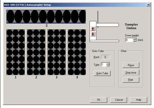
31 Software Overview The onefast software must be running to enable the use of the onefast system. Additionally, ESI recommends that the following order of start-up be followed. Starting order of configuration components: 1) Power on autosampler and onefast modules. 2) Start the onefast software and verify that all devices were detected. 3) Start the instrument software. The main window contains the following controls which may be used to configure the autosampler racks, operate onefast modules or enable/disable the FAST method. Please refer to Figure 14: Main window of onefast software. The autosampler graphic will change to reflect the autosampler detected when the onefast software is started. If no autosampler is found, the message No Autosampler Found will be visible instead. Figure 14: Main window of onefast software. Clicking on the rack locations in the autosampler graphic will permit the user to place a desired rack from a given list as shown in Figure 15. Clicking on the image will toggle the valve between Load and Inject positions. The current position of the valve is also reflected in the image. Clicking on the checkbox will enable or disable the FAST method from processing instructions received from the instrument software. 30

32 Clicking on the image will toggle the vacuum between ON and OFF. The current state of the vacuum is also reflected in the image. When placing desired racks onto the image of the autosampler, additional options may be available depending on emulation and autosampler. Choices/settings available through the Rack window will include: Specification of probe Down Height, or the depth, that the probe will advance into the sample tube, Specification of the order or direction that the tubes will be counted/incremented within the rack. Figure 15: Racks Window and settings. Menu Items The main window provides access to the following windows or selections: ESI onefast>>file This menu permits the user to close the application and thereby saving current configuration. ESI onefast>>ports The Ports window, Figure 16, will provide access to manually configure the onefast system. In most cases, the user will not need to use this window other than during the initial selection of a Virtual Port during initial setup. All three status bars should be green when the system is properly configured. 31

33 The tab labeled ESI Configured Ports presents information regarding both hardware devices and communication ports used. Hardware information located in the Emulation grouping includes the type of Autosampler used and the type of Instrument or host software that will control the autosampler and onefast. The Port Number refers to the COM port number that is associated with the serial port that is connected to the autosampler. This serial port may be a 9-pin port on the computer or a USB-serial port. The value Port Number in the Instrument Port (instrument) grouping specifies the port number to be used when the onefast software creates a COM port that is used for communication between the Instrument software and the onefast software. If the configuration uses a physical COM port, it will be identified accordingly. The user can select the type of connection between the onefast software and the instrument software by choose RS-232 Virtual or RS-232 Physical. The tab labeled All System Ports provides some assistance in determining which devices are connected to a given port. Figure 16: Ports Window. ESI onefast>>fast This window provides access to the FAST method assigned to the current onefast configuration. The following controls are available to the user. See Figure 17 1) A method can be opened or saved using the File menu. 2) FAST Method File Name: identifies the name of the current FAST method. 3) A FAST Method can be created by Drag-and-Dropping from the Events and Actions listings. 4) Rinse Time (sec): Shows how long the probe will stay at the rinse station(s). 5) Enable FAST Control: Activates or de-activates the FAST method from executing when instructions are received from the instrument. If not checked, the autosampler will behave as instructed by the instrument and no FAST actions will be processed. 32

34 6) Vacuum Time (sec): Limits the length of time that the vacuum will remain on at the end of an analysis sequence. 7) Manual Controls: Allows the user to manually operate the FAST valve and vacuum. Figure 17: FAST method window. Integration with an SC Autosampler will provide the full set of FAST features; however, depending on the autosampler used, some features may not be available. ESI onefast>>about The About menu will contain information regarding version number and access to help documents. onefast Applications A typical sample analysis will consist of a FAST method as outlined in the following Figure

35 Figure 18: Typical FAST Method. The arrangement of the FAST method associates corresponding Actions in the second column, to Events defined in the first column. Parameters if required, can be entered/modified in the third column. In the example from Figure 18, the following lines result in the following actions or movements of FAST components. a) When the host instrument instructs the probe to move down into a sample (On Probe Down), the Vacuum will turn ON (Vacuum On 0) and the FAST Valve will move to the Load position (Load 0). b) When the probe reaches the bottom of the sample tube (Probe In Sample) a timer is started that will expire after 10 seconds, (Timer A)(10). c) When Timer A expires, the FAST Valve will move to the Inject position (Inject 0) and the autosampler will be instructed to wash/rinse the probe, (Move Rinse). d) When the probe wash has finished, the autosampler will be instructed to move over the next predicted sample tube (Move Next). e) When the host instrument sends a wash/rinse instruction (On Rinse), the FAST valve will move to the Load position (Load 0). Typical Sample Analysis The typical sample analysis will consist of configuring the loading and injecting of a loop of sample to the nebulizer. In addition, the onefast software will manage the operations of the FAST valve, vacuum, and autosampler, while synchronizing to the control of the host software that manages the instrument. The two basic arrangements of the system and liquid flow paths are illustrated in the following diagrams. 34

36 Figure 19: Load position. At the beginning of a sample analysis, the vacuum will rapidly draw sample through the autosampler probe and Load the loop. At the same time the instrument s peristaltic pump will advance clean carrier solution to nebulizer. Figure 20: Inject Position. With a full loop of sample, the valve will then be switched to the Inject position, where the clean carrier will advance the sample volume to the nebulizer and into the instrument to be analyzed. In a well configured system the FAST valve will be positioned as close as possible to the nebulizer therefore reducing the time necessary for the sample to arrive at the nebulizer. The resulting benefits to a sample analysis due to the implementation of the onefast can include the following: 1) Reduced sample analysis time. Refer to Figure 21. Shown is an example of how the analysis time is reduced. 2) Reduced instrument maintenance. Since the sample loop is the only sample volume that is presented to the spray chamber, system maintenance and cleaning is reduced since less dirty sample material will deposit on surfaces such as cones. 35
37 Figure 21: Example of reduced analysis time. Tuning the Instrument when connected to FAST If the instrument requires routine calibration, this can be accomplished by moving the carrier probe from the carrier solution and placing it in the tuning solution. Simply place the probe back into the carrier in preparation for sample analysis. Important Design Criteria for a FAST Method The following should be considered when improving performance and increasing throughput with the use of the onefast system. Use the smallest possible loop that will still provide enough sample volume required for analysis. The basic elements of a sample analysis consist of 1) autosampler movement, 2) sample uptake time, 3) stabilization time, 4) measurement time, 5) instrument overhead time and 6) rinse/wash time. The FAST system can reduce sample analysis time by efficiently transporting the sample to the nebulizer then simultaneously rinsing the transport line and probe while the instrument is analyzing the sample. Higher sample throughput and shorter sample analysis times require the selection of a loop that will both provide an adequate sample volume for measurement and also be as small as possible to reduce loading and rinse times. 36
38 Setting Read Delay The optimum Read-Delay should be determined so that the ICP method can start measurements as soon as possible. The effective Read-Delay time in the instrument method will include the following: a) Loop Load time in the FAST method, b) Sample travel time from valve to nebulizer, c) Signal stabilization time. Figure 22: Signal Intensity during FAST method. The suitable Read-Delay will be the time between when the instrument tells the probe to move into the sample vial and when the signal has stabilized. This example diagram, see Figure 22, represents a series of 13 replicates. If each replicate is 1 second long and the first starts 4 seconds after the probe has entered the sample vial, it is reasonable to consider a Read-Delay of approximately 6 seconds. The diagram also indicates that there is approximately 8 seconds of stable signal for analysis. Setting Wash/Rinse Time It is important to configure the instrument s wash/rinse time sufficiently long so that the following two actions occur. 1) When the wash/rinse instruction is received from the host instrument, the valve will switch to Load and the loop will evacuate. 2) The MoveNext action should occur, placing the probe above the next predicted sample before the wash/rinse time expires. Additional Features The following is a list of additional features provided by the onefast system. These are often dependent on the host instrument and autosampler combination used. 1) Flexibility in generating a combination of different rack types within the same layout, 2) Control of tube count directions within the rack, 37
39 Maintenance Maintenance for High Flow FAST Valve Initial Precaution All surfaces of the valve should be clean and free of contaminants and must be kept clean to prevent valve damage. Open ports and fittings cause unnecessary risk of particulate matter entering the valve and scratching the sealing surfaces, which is the most frequent cause of premature valve failure. Disassembly and Cleaning 1. Cleaning a valve can often be accomplished by flushing all the lines with appropriate solvents, such as isopropyl alcohol. Do not disassemble the valve unless system malfunction is definitely isolated to the valve. 2. To disassemble the valve, use a 7/64 hex driver to remove the socket head screws which secure the stator and body ring onto the valve body. Figure 23: Exploded View of the High Flow Valve 3. To prevent any damage to the sealing surface of the stator, rest it on its outer face. If the tubing is still connected, leave it suspended by the tubing. 4. With your fingers or a small tool, gently pry the rotor away from the driver on the body of the valve. 5. Examine the rotor sealing surface for scratches. If scratches are visible to the naked eye, the rotor must be replaced. 6. Clean all parts thoroughly with an appropriate solvent, such as isopropyl alcohol, while taking care that no surfaces get scratched. 7. Carefully examine all ports in the stator for Teflon shavings. If shavings are present, use canned air to direct airflow from the opposite side of the stator through each individual port. 38


40 8. Use a foam swab with isopropyl alcohol to gently clean the threads of the port, being careful not to force any shavings deeper into the port. Once this has been completed, repeat step 7 with canned air. Reassembly 1. Replace the rotor in the driver on the body, making sure that the rotor sealing surface, with its engraved flow passages, is facing out. The pattern is asymmetrical to prevent improper placement so be sure to align the rotor correctly into the slots on the driver. Figure 24: Replacing rotor into the driver. 2. Replace the body ring, being careful to align the holes for the socket head screws. Figure 25: Replacing body ring. 3. Replace the stator by aligning the two holes on the back of the stator with the pins on the body of the valve. The pattern is asymmetrical so be sure that the holes for the socket head screws are aligned. 39


41 Figure 26: View of aligning pins and replacing the stator. Figure 27: Correctly aligned stator left, and incorrect on right. 4. Insert socket head screws and tighten them gently until snug. Be careful not to over-tighten them! The screws simply hold the assembly together and do not affect the sealing force, which is automatically set as the screws tighten the stator against the valve body. Figure 28: Reassembled High-Flow Valve. 5. Valve reassembly is now complete, and the lines for the FAST valve can now be reconnected. 6. Attach ends of the loop with white fittings to port #1 and to port #4 on the stator of the FAST valve. 40
42 7. Attach the Carrier In line with red fitting to port #2. 8. Attach the Nebulizer line with green fitting to port #3. 9. Attach the Probe line with blue fitting to port # Attach the Vacuum line with black fitting to port #6. Technical Notes This section contains technical notes. Document Number Title Description TN Autostart Batch File Examples onefast Examples of batch files that can be used to start the onefast software and instrument software. TN Using a GPIB 232CV A with onefast Use of National Instruments GPIB 232CV A with onefast. TN Using an ICS 4894 with onefast Use of an ICS 4894 with onefast. TN Virtual Port not Visible in PlasmaLab Desired COM port is not available through PlasmaLab TN Setting Background Services Priority Recommended to improve system performance. TN Elevating the Priority of onefast Assists to overcome resource limitations on computer. 41
43 Autostart Batch File Examples onefast (TN280508) The user may choose to create an Autostart Batch file that will start both the instrument software and the onefast software by clicking a single icon. It is recommended that the created batch file be properly tested and evaluated before use. 42
 along with a DB9 M/F Serial Cable (SC-0904), can be used to connect the converter to the computer.")
44 Using a GPIB 232CV A with onefast (TN290508) This document will illustrate the proper configuration and use of a National Instruments GPIB-232CV-A that is provided with the AS-93+ or the ASX-500. The combination of these DIP switch settings and the addition of a Null adapter (SC-0906) along with a DB9 M/F Serial Cable (SC-0904), can be used to connect the converter to the computer. Hardware installation procedure: Figure 29: Dip Switch Settings to connect GPIB 232CV-A to DB9 on host computer. 1) Verify that the GPIB-232CV-A was originally configured for the autosampler. Incorrect firmware will prevent proper installation. 2) Remove the existing serial cable and replace with Null adapter (SC-0906) and DB9 M/F Serial Cable (SC- 0904). See Figure 29: Dip Switch Settings to connect GPIB 232CV-A to DB9 on host computer. 3) Secure other end of Serial Cable (SC-0904) to a serial port on host computer. 43
 Remove serial cable between autosampler and GPIB Interface (SC-0901-14). Also remove any null adapter that may present.")
45 Using ICS 4894 with onefast (TN010608) The ICS 4894 should be connected as shown in the attached Figure 30: Connections for ICS Hardware installation procedure: Figure 30: Connections for ICS ) Remove serial cable between autosampler and GPIB Interface (SC ). Also remove any null adapter that may present. Please refer to Technical Note (TN290508) if the GPIB interface is a NI GPIB-232-CV-A. 2) Connect GPIB Interface to computer using a USB-Serial Adapter (SC-0905) and DB25/DB9 Null Cable (SC-0903). 44

 Log onto the PlasmaLab computer with Administrator privileges and determine which ports need to be made available")
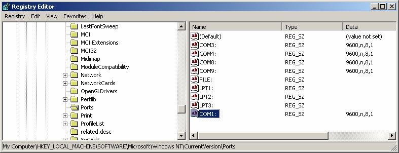
46 Virtual Port not visible in PlasmaLab (TN040908) Description: After the installation of onefast Software, the proper COM port is visible in the Windows Device Manager but not visible in the Accessory setup and control window of PlasmaLab. 1) Log onto the PlasmaLab computer with Administrator privileges and determine which ports need to be made available in the Accessory setup and control window. COM1 not available from Pull-Down 2) Run regedit as an administrator. 45


 The Registry should now")
47 3) Navigate to: HKEY_LOCAL_MACHINE\Software\Microsoft\Windows NT\CurrentVersion\Ports 4) Add a new REG_SZ entry for the virtual serial port (in this case, COM1:) 5) Set the Data to be 9600,n,8,1: 6) The Registry should now resemble the following window with the entry: 46
48 47
49 48


50 Setting Background Services Priority (TN050808) Depending on peripheral devices that are connected to computer, such as printers or USB connections, the following adjustment is recommended to improve communication performance. The following step can be taken to correct the problem: Open Control Panel>>System>>Advanced>>Performance Settings>>Advanced and set the Processor scheduling to Background services. See Figures below. 49

51 Elevating Priority of onefast (TN061108) Changing the priority of the onefast software may ease resource limitations of computer. The following steps can be taken to test for the problem. The settings will revert to original settings at the next start of the onefast program. 1) After starting the onefast software, use Ctrl-Alt-Del to access the task manager and switch to the Processes tab. 2) Locate and right-click on the onefast.exe and select Set Priority and choose High. 3) Run onefast and evaluate. Note that this setting is maintained only until the onefast software is shut down. 4) If the application of this setting proves to resolve resource issues, the setting can be configured automatically through he use of a batch file. Please contact ESI support for assistance. 50
ELEMENTAL SCIENTIFIC ESI SC. Installation and Software Guide
 ELEMENTAL SCIENTIFIC ESI SC Installation and Software Guide ESI SC Version 2.6.0 Installation and Software Guide Elemental Scientific 1500 North 24th Street Omaha, NE 68110 USA Phone 402.991.7800 Fax 402.991.7799
ELEMENTAL SCIENTIFIC ESI SC. Installation and Software Guide
 ELEMENTAL SCIENTIFIC ESI SC Installation and Software Guide ESI SC Version 2.9 Installation and Software Guide Elemental Scientific 7277 World Communications Drive Omaha, NE 68122 USA Phone 402.991.7800
Agilent ICP-OES SVS 2 Productivity Package Installation and Upgrade Instructions
 Agilent ICP-OES SVS 2 Productivity Package Installation and Upgrade Instructions NOTICE: This document contains references to Varian. Please note that Varian, Inc. is now part of Agilent Technologies.
ASXPRESS PLUS Rapid Sample Introduction System Quick Installation Guide
 ASXPRESS PLUS Rapid Sample Introduction System Quick Installation Guide Manual Part Number 610092 Rev 8 ASXPRESS PLUS Quick Installation Guide You can and should arrange for expert installation of the
CETAC ASXPRESS PLUS Rapid Sample Introduction System Upgrade for XLR-8 Autosamplers
 CETAC ASXPRESS PLUS Rapid Sample Introduction System Upgrade for XLR-8 Autosamplers Installation Guide Manual Part Number 480197 rev1 COPYRIGHT 2012 CETAC Technologies 480197 rev1, July, 2012 CETAC Technologies
Cheminert Model C52 and C62(Z) Injectors
 Injectors") Technical te 9 Valco Instruments Co. Inc. Cheminert Model C and C(Z) Injectors Installation and Maintenance The Cheminert C (HPLC) and C (LC) series injectors are integrated motor/valve assemblies designed
Technical te 9 Valco Instruments Co. Inc. Cheminert Model C and C(Z) Injectors Installation and Maintenance The Cheminert C (HPLC) and C (LC) series injectors are integrated motor/valve assemblies designed
CETAC ASX-520 Family SpeedShift Utility
 CETAC ASX-520 Family SpeedShift Utility Software User's Guide Manual Part Number 480182 Rev 3a COPYRIGHT 2010-2011 CETAC Technologies 480182 Rev 3a, February, 2011 CETAC Technologies authorizes its customers
CETAC ASX-520 Family SpeedShift Utility Upgrade Kit
 CETAC ASX-520 Family SpeedShift Utility Upgrade Kit Installation Guide Manual Part Number 480174 Rev 3a COPYRIGHT 2010-2011 CETAC Technologies 480174 Rev 3a, February, 2011 CETAC Technologies authorizes
Cheminert Model C55 and C65(Z) Selectors
 Selectors") Technical te 8 Valco Instruments Co. Inc. Cheminert Model C and C(Z) Selectors Installation and Maintenance The Cheminert C (HPLC) and C (LC) series selector are integrated motor/valve assemblies designed
Technical te 8 Valco Instruments Co. Inc. Cheminert Model C and C(Z) Selectors Installation and Maintenance The Cheminert C (HPLC) and C (LC) series selector are integrated motor/valve assemblies designed
Dionex AS-AP Sample Conductivity and ph Accessory Setup and Operation Guide
 Dionex AS-AP Sample Conductivity and ph Accessory Setup and Operation Guide Document No. 065470 Revision 02 February 2012 2012 by Thermo Fisher Scientific Inc. All rights reserved. Chromeleon is a registered
ASXPRESS Rapid Sample Introduction System ACCESSORIES AND SUPPLIES CATALOG
 ASXPRESS Rapid Sample Introduction System ACCESSORIES AND SUPPLIES CATALOG See the ASXPRESS PLUS Rapid Sample Introduction System Accessories and Supplies Catalog for additional parts. The ASXPRESS Rapid
FlowAccess TM GETTING STARTED. Windows software for Skalar SAN plus systems. Version and up
 FlowAccess TM V3 Windows software for Skalar SAN plus systems Version 3.1.0.4 and up GETTING STARTED FlowAccess TM V3 Windows software for Skalar SAN plus systems Version 3.1.0.4 and up Getting started
ASX-260 RANDOM ACCESS AUTOSAMPLER ACCESSORIES AND SUPPLIES CATALOG
 ASX-260 RANDOM ACCESS AUTOSAMPLER ACCESSORIES AND SUPPLIES CATALOG CETAC Technologies 14306 Industrial Road Omaha, Nebraska 68144, USA Phone: (402) 733-2829 Fax: (402) 733-5292 e-mail: custserv@cetac.com
Using the SASS 2300 Wetted-Wall Air Sampler
 Wetted-Wall Air Sampler Front View Features Rear View Features Setting Up the SASS 2300 System Connect Wall Power Transformer Connect System Electrical Power The SASS 2300 requires 12-24 VDC from either
The Olis Titrator Series
 The Olis Titrator Series Perfect Titrations into any type of cuvette With considerable effort, one can do precise titration studies by hand. Or, one can let the OLIS titrators do the technician s work
HITACHI LACHROM ELITE
 HITACHI LACHROM ELITE Clarity Control Module ENG Code/Rev.: M133/60D Date: 7/16/2018 Phone: +420 251 013 400 DataApex Ltd. Fax: +420 251 013 401 Petrzilkova 2583/13 clarity@dataapex.com 158 00 Prague 5
Manual for MantraJet 1100 CD/DVD auto-printer
 Manual for MantraJet 1100 CD/DVD auto-printer Rev 1.03 September 7, 2010 Table of contents Specifications...3 Unpacking MantraJet 1100...4 Quick installation reference MantraJet 1100...7 Installation of
Removal and Installation8
 8 Screw Types 8-4 Top Cover Assembly 8-5 Left Hand Cover 8-6 Right Hand Cover 8-10 Front Panel Assembly 8-14 Left Rear Cover 8-15 Right Rear Cover 8-16 Extension Cover (60" Model only) 8-17 Media Lever
Thermal Transient Test
 Thermal Transient Test Installation and Operating Manual 2705-A De La Vina Street Santa Barbara, California 93105 Telephone (805) 682-0900 www.designconsultants.cc Hardware Installation Installation 1.
G12/G12x USER S MANUAL
 G12/G12x USER S MANUAL TABLE OF CONTENTS SECTION 1 SLIDE CONFIGURATION SECTION 2 SLIDE CONFIGURATION ACCESSORIES SECTION 3 TABLETOP CONFIGURATION SECTION 4 TABLETOP CONFIGURATION ACCESSORIES SECTION 5
PC 3x Software Installation and Operation (TN050312)
") PC 3x Software Installation and Operation (TN050312) PC 3x Hardware Description The PC 3x is a compact Peltier cooled inlet system which incorporates the ESI cyclonic spray chamber similar to the existing
PC 3x Software Installation and Operation (TN050312) PC 3x Hardware Description The PC 3x is a compact Peltier cooled inlet system which incorporates the ESI cyclonic spray chamber similar to the existing
Data Acquisition with CP-2002/2003 Micro-GC Control
 Varian Analytical Instruments 2700 Mitchell Drive Walnut Creek, CA 94598 Star Chromatography Workstation Version 6 Data Acquisition with CP-2002/2003 Micro-GC Control Operation Manual Varian, Inc. 2002
Omnion 3.0 Software USER MANUAL. June 2006, Edition 3. Hach Company, All rights reserved. Printed in the U.S.A. te/dk
 02134 Omnion 3.0 Software USER MANUAL June 2006, Edition 3 Hach Company, 2006. All rights reserved. Printed in the U.S.A. te/dk Visit us at www.lachatinstruments.com Table of contents Section 1 Introduction...
Subj: Tester Interface Configuration and Software Installation
 Radiant Technologies, Inc. 2835D Pan American Freeway NE Albuquerque, NM 87107 Tel: 505-842-8007 Fax: 505-842-0366 e-mail: radiant@ferrodevices.com 9 November, 2010 From: Scott P. Chapman Radiant Technologies,
MULTICOM. Clarity Hardware. Code/Rev.: M110/80A Date: 8/15/2018. Fax: Petrzilkova 2583/ Prague 5
 MULTICOM Clarity Hardware ENG Code/Rev.: M110/80A Date: 8/15/2018 Phone: +420 251 013 400 DataApex Ltd. Fax: +420 251 013 401 Petrzilkova 2583/13 clarity@dataapex.com 158 00 Prague 5 www.dataapex.com The
Guidebook for Installation and Familiarization. HP 1100 Series Combinatorial Chemistry Analysis System
 Guidebook for Installation and Familiarization HP 1100 Series Combinatorial Chemistry Analysis System Copyright Hewlett- Packard Company 1997 All rights reserved. Reproduction, adaption, or translation
870 KF Titrino plus. Installation and tutorial EN
 870 KF Titrino plus Installation and tutorial 8.870.8004EN Metrohm AG CH-9101 Herisau Switzerland Phone +41 71 353 85 85 Fax +41 71 353 89 01 info@metrohm.com www.metrohm.com 870 KF Titrino plus Installation
Analyst QS. Administrator s Guide. Part Number: B July 2004
 Analyst QS Administrator s Guide Part Number: 1001930 B July 2004 http://www.appliedbiosystems.com This document is provided to customers who have purchased MDS Sciex equipment to use in the operation
VISY-X. Technical Documentation. Subsequent installation of VISY-Density. Edition: Version: 2 Art. No.:
 Technical Documentation VISY-X Subsequent installation of VISY-Density Edition: 2016-08 Version: 2 Art. No.: 350063 FAFNIR GmbH Schnackenburgallee 149 c 22525 Hamburg Tel.: +49 / 40 / 39 82 07 0 Fax: +49
CyberComm Pro 2.4 Data Acquisition Software Installation & User Guide. CyberScan DO 1500
 CyberComm Pro 2.4 Data Acquisition Software Installation & User Guide CyberScan DO 1500 Bench Dissolved Oxygen Meter Technology Made Easy... 68X292341 Rev.0 01/04 PREFACE Thank you for selecting the CyberScan
Upgrading Firmware for the CETAC ASXPRESS PLUS Rapid Sample Introduction System
 Upgrading Firmware for the CETAC ASXPRESS PLUS Rapid Sample Introduction System Installation Guide 610094 Revision 3 1 COPYRIGHT 2010, 2011, 2015 Teledyne Technologies Inc. 610094 Revision 3, April, 2015
NAV-1 Lens Support. NAV-2 Lens Support BEFORE YOU BEGIN
 INSTALLATION Lens Support INSTRUCTIONS The Lens Support is compatible with any RPA projector mount. The readily adapts to the following ScreenStar Conversion Lens from Navitar: SSW08 and SST120. LENS SUPPORT
Remanufacturing the Brother HL-1240 OPC (Drum) Cartridge (DR-400, DR-6000)
 Cartridge (DR-400, DR-6000)") Remanufacturing the Brother HL-1240 OPC (Drum) Cartridge (DR-400, DR-6000) These instructions cover the recycling of the Brother DR-400 OPC cartridge used in laser printers and plain paper fax machines
Remanufacturing the Brother HL-1240 OPC (Drum) Cartridge (DR-400, DR-6000) These instructions cover the recycling of the Brother DR-400 OPC cartridge used in laser printers and plain paper fax machines
SoftTools Suite 7.0. Flowserve Corporation
 SoftTools Suite 7.0 Quick Start Guide for SoftTools 7.0 with support for the HART Communications Protocol on the Logix 1200/1200e, 3200IQ, and 500/500si Series Positioners Flowserve Corporation Flow Control
CyberComm Pro Data Acquisition Software Installation & User Guide
 CyberComm Pro 2.2.3 Data Acquisition Software Installation & User Guide ph 1100 and ph 2100 Bench ph and Bench ph/ion Meter Technology Made Easy... 68X090822 rev 1 Aug 2002 2 PREFACE Thank you for selecting
TeamBoard Quick Start #1
 www.touchboards.com 205 Westwood Ave.Long Branch, NJ 07740 1-866-942-6273 Sales@touchboards.com Quick Start #1 Welcome to! These Quick Start Cards address some basics, from installation steps to creating
2-1. the ESI Probe Assembly. the PEEK Safety Sleeve and Sample Tube to the ESI Probe
 You tune and calibrate your LCQ Advantage in ESI mode before you acquire data in either the ESI or the APCI mode. This chapter contains the following topics:.removing.connecting.installing.setting.setting
Standard Operating Procedure for the HPLC-ICP-MS System By Celina Dozier Fall 2017
 Standard Operating Procedure for the HPLC-ICP-MS System By Celina Dozier Fall 2017 Introduction This document is only for operation of the HPLC and ICP-MS instruments to obtain data. It contains no maintenance
Procedure to set up an HPIB 82350B card on an M57. M58 or C20x PC. Table 1: Parts required. Part Number Description Qty
 1 OF 21 Procedure to set up an HPIB 82350B card on an M57. M58 or C20x PC Parts required Table 1: Parts required Part Number Description Qty 289000764 Kit, HPIB Card, Inter, PCI 1 Procedure The procedure
Installation of Hot Disk v 7.3 and later on a PC with Windows 7, 8 or 10
 Installation Instruction for Hot Disk TPS 7 2.1 2017-05-09 1(44) Installation of Hot Disk v 7.3 and later on a PC with Windows 7, 8 or 10 Installation Instruction for Hot Disk TPS 7 2.1 2017-05-09 2(44)
The following forms are included. Computer files are contained in the directory v:\aqg_ops\improve\field_information\mailaudt. 1point.
 TI 201B Forms for Flow Audits by Site Operators The following forms are included. Computer files are contained in the directory v:\aqg_ops\improve\field_information\mailaudt date initials 1point.doc 10/20/95
Dome C3i Digital Flat-Panel Display Dome DX2/PCI Display Controller Dome CXtra Software QUICK REFERENCE. Windows XP Windows 2000
 America Sales Planar Systems, Inc. 1195 NW Compton Drive Beaverton, OR 97006-1992 USA phone + 1 (503) 748-1100 fax + 1 (503) 748-1493 Medical Sales Planar Systems, Inc. 400 Fifth Avenue Waltham, MA 02451-8738
Unpacking and Installing the Flora 2512 UV Printer. Steps 1: Unscrew the 10mm bolts holding the top. Then remove the top and put in a safe place.
 Unpacking and Installing the Flora 2512 UV Printer Steps 1: Unscrew the 10mm bolts holding the top. Then remove the top and put in a safe place. Step 2: Unscrew 10mm bolts holding the end panels. On the
Written By: Sam Lionheart
 iphone 6 Wi-Fi Antenna Replacement How to replace the Wi-Fi antenna in an iphone 6. Written By: Sam Lionheart ifixit CC BY-NC-SA www.ifixit.com Page 1 of 18 INTRODUCTION Spotty signal on wi-fi? You may
BioRobot 9604 Operating Procedure
 BioRobot 9604 Operating Procedure Note: An import table (directions given in number 20) must be made prior to a robot run. 1. Prior to operating the BioRobot 9604, perform all daily and weekly maintenance
MantraJet 1100 CD/DVD autoprinter Operator s manual
 MantraJet 1100 CD/DVD autoprinter Operator s manual Rev 1.00 May 7, 2008 Table of contents 1. Specifications.. Page 2 2. Unpacking you MantraJet 1100 Page 3 3. Using your autoprinter for the first time.
medtester 5000C Automated Biomedical Equipment Test System
 medtester 5000C Automated Biomedical Equipment Test System Field Upgrade Installation Instructions PN 2245628 April 2005 2005 Fluke Corporation, All rights reserved. Printed in USA All product names are
TABLE OF CONTENTS SECTION 1 TABLETOP CONFIGURATION SECTION 2 TABLETOP CONFIGURATION ACCESSORIES SECTION 3 SLIDE CONFIGURATION
 S6 USER S MANUAL TABLE OF CONTENTS SECTION 1 TABLETOP CONFIGURATION SECTION 2 TABLETOP CONFIGURATION ACCESSORIES SECTION 3 SLIDE CONFIGURATION SECTION 4 SLIDE CONFIGURATION ACCESSORIES SECTION 5 RACK MOUNT
Procedures of the simaa 6000 (perkin elmer verison 2.5 aa winlab) Simultaneous multi-element graphite furnace Atomic absorption spectrophotometer(aa)
 Simultaneous multi-element graphite furnace Atomic absorption spectrophotometer(aa)") Παγε 1 οφ 5 Procedures of the simaa 6000 (perkin elmer verison 2.5 aa winlab) Simultaneous multi-element graphite furnace Atomic absorption spectrophotometer(aa) PREPARING THE AA INSTRUMENT FOR GSR ANALYSIS.
Παγε 1 οφ 5 Procedures of the simaa 6000 (perkin elmer verison 2.5 aa winlab) Simultaneous multi-element graphite furnace Atomic absorption spectrophotometer(aa) PREPARING THE AA INSTRUMENT FOR GSR ANALYSIS.
Bent Pins Inside the Sample Chamber
 PPMS Service Note 1070-311 Bent Pins Inside the Sample Chamber It has come to the attention of Quantum Design that there has been an increase in the instances of sample chambers with bent pins. We would
Peel & Present Option Rev.C
 Peel & Present Option 92-2479-01 Rev.C Contents of the Peel & Present Kit This kit contains the following items: Peel and Present Mechanism Assist Roller Bushing Follow the steps below to install these
Operating Manual. GC-APPI Inferface for:
 Operating Manual GC-APPI Inferface for: Q-Exactive TM MS, Exactive TM MS, and LTQ Orbitrap TM Series MS P/N: MC510000, P/N: MC511000, P/N: MC512000 Revision C GC-APPI-Interface 2016 MasCom Technologies
Integrating the Measurand Shape Accelerometer Arrays (SAA) Sensor Application Note #19
 Sensor Application Note #19") 5 Gould Road, PO Box 2155 New London, NH 03257 USA Voice: (603) 526-9800 info@canarysystems.com www.canarysystems.com Integrating the Measurand Shape Accelerometer Arrays (SAA) Sensor Application Note
5 Gould Road, PO Box 2155 New London, NH 03257 USA Voice: (603) 526-9800 info@canarysystems.com www.canarysystems.com Integrating the Measurand Shape Accelerometer Arrays (SAA) Sensor Application Note
HT3X00A. Clarity Control Module. Code/Rev.: M153/50E Date: 11/13/2018. Fax: Petrzilkova 2583/ Prague 5
 HT3X00A Clarity Control Module ENG Code/Rev.: M153/50E Date: 11/13/2018 Phone: +420 251 013 400 DataApex Ltd. Fax: +420 251 013 401 Petrzilkova 2583/13 clarity@dataapex.com 158 00 Prague 5 www.dataapex.com
Thermal Transient Test Installation and Operating Manual
 Thermal Transient Test Installation and Operating Manual 2705A De La Vina Street Santa Barbara, California 93105 Telephone (805) 682-0900 descon@silcom.com www. santabarbaraautomation.com Installation
Procedure to Upgrade from B&W Maintenance Panel to TIB Color Touchscreen Door in a Working Maxum or Maxum II Analyzer Equipped With a SYSCON2
 Procedure to Upgrade from B&W Maintenance Panel to TIB Color Touchscreen Door in a Working Maxum or Maxum II Analyzer Equipped With a SYSCON2 Difficulty Level: High Estimated time to execute: 3 Hours Revision
Calibration and Maintenance
 Epson DX5 X 1 Printhead Calibration and Maintenance 31 st Jan., 2013 Version V3.0 1 Contents Chapter 1: Computer Requirement...3 Chapter 2:Installation...4 Chapter 3:Characteristic...5 Chapter 4:Board
Magnetic Immunoassay Reader Operator Manual
 Page 1 of 8 Magnetic Immunoassay Reader Operator Manual Table of contents 1 Introduction...1 2 Magnetic Immunoassay Reader...1 2.1 Contact information and spare parts...1 3 Contents of delivery...1 4 Technical
FluoroSELECT Fluorometer User s Manual
 FluoroSELECT Fluorometer User s Manual Version 4.4.A Sigma-Aldrich Chemie GmbH Industriestrasse 25 CH-9470 Buchs Switzerland EurTechServ@sial.com techservice@sial.com (US and Canada) sigma-aldrich.com
Versatile. Innovative. Customizable M CVAF Mercury Analyzer
 Versatile Innovative Customizable CVAF Mercury Analyzer M-8000 The QuickTrace M-8000 Cold Vapor Atomic Fluorescence mercury analyzer (CVAF) is ideal for ultra-trace to sub-mg/l mercury quantitation. It
ABI PRISM 7700 Sequence Detection System: Routine Maintenance
 ABI PRISM 7700 Sequence Detection System: Routine Maintenance Overview The ABI PRISM 7700 Sequence Detection System (SDS) and the Macintosh computer that runs the SDS need to be properly and routinely
Breeze 2 Installation and Configuration Guide
 Breeze 2 Installation and Configuration Guide 715001951/Revision B Copyright Waters Corporation 2008 2009 All rights reserved Copyright notice 2008 2009 WATERS CORPORATION. PRINTED IN THE UNITED STATES
Technical Information
 Technical Information DATE: January 16, 2014 MODEL: RSP 1570, RSX 1550, RSX 1560 Main Software Upgrade Instructions The RSP-1570, RSX-1550 and RSX-1560 have three separate software modules main software,
TopPoint Administrator User's Guide
 TopPoint Administrator User's Guide LT2153/ 2000 Gilson, Inc. All rights reserved December 2000 Table of Contents 1 Introduction 2 Installation 3 Operation System Requirements... 1-2 Minimum... 1-2 Recommended...
FROG-4000TM Quick Start Guide
 FROG-4000TM Quick Start Guide 1 Precautions DO NOT invert the instrument with the sparge bottle attached. DO NOT transport or store the instrument with liquid in the sparge bottle. DO NOT handle or carry
MVX-7100 µl Workstation
 MVX-7100 µl Workstation Operator s Manual Manual Part Number 480220 Rev 1 COPYRIGHT 2015-2017 Teledyne Technologies Incorporated. All rights reserved. 480220 Rev 1, April, 2017 Teledyne CETAC Technologies
Ioline CrystalPress. Quick Start Guide
 Ioline CrystalPress Quick Start Guide The Quick Start Guide is intended to help a new user of the Ioline CrystalPress get everything setup and running quickly. Please note that there are important notices,
OPERATION MANUAL SERIES BORESCOPES INSTRUMENT TECHNOLOGY, INC. POB 381, Westfield, MA Airport Road, Westfield, MA 01085
 OPERATION MANUAL SERIES 123000 BORESCOPES INSTRUMENT TECHNOLOGY, INC. POB 381, Westfield, MA 01086 33 Airport Road, Westfield, MA 01085 Tel: (413) 562-3606 Fax: (413) 568-9809 Email: iti@scopes.com www.scopes.com
RISC OS 3 software upgrade fitting instructions
 RISC OS 3 software upgrade fitting instructions Contents Page number Introduction 2 Packing list 2 An overview of the software upgrade procedure 4 Identifying your upgrade 4 Upgrading your computers hardware
INTERFACE & SOFTWARE GUIDE
 TM INTERFACE & SOFTWARE GUIDE Wireless Remote Display USB Converter Battery Sensor Setup DataLogger Software r e m o t e i n t e r f a c e escape enter status w w w. s k y s t r e a m e n e r g y. c o
Manual for the MicroSIA Instrument
 Manual for the MicroSIA Instrument Version 1.1 1 FIAlab Instruments, Inc., 2151 N. Northlake Way, Suite 100, Seattle, WA 98103 USA Table of Contents 1 INTRODUCTION... 3 1.1 GENERAL... 3 1.2 OPERATION PRINCIPLE...
Instruction Manual. RS 3D Printer
 Instruction Manual RS 3D Printer 1) GENERAL This instruction manual contains important information regarding the installation, operation, maintenance and storage for RS 3D Printer. Please read these instructions
Written By: Andrew Optimus Goldberg
 ipad Air LTE SIM Board Replacement Replace the SIM board (a.k.a. SIM card bay) on an ipad Air LTE. Written By: Andrew Optimus Goldberg ifixit CC BY-NC-SA www.ifixit.com Page 1 of 32 INTRODUCTION Use this
Setting up an Intermec PM43 printer with InterDriver version M-0 or newer
 Setting up an Intermec PM43 printer with InterDriver version 7.3.5 M-0 or newer Setting up a bar code printer with 7.3.5 M-0 Intermec drivers or newer 1 INITIAL PRINTER CONFIGURATION When the printer is
ULTRATRAK RM4000 QUICK START GUIDE. Version 1.3
 ULTRATRAK RM4000 QUICK START GUIDE Version 1.3 UltraTrak RM4000 Copyright 2002, Promise Technology, Inc. Copyright by Promise Technology, Inc. (Promise Technology). No part of this manual may be reproduced
IRF90 - Rotating Focuser
 IRF90 - Rotating Focuser Part # 600180 REV092111 Page 1 Contents Introduction and Overview... 3 Limitations... 3 Packing List... 4 Installation... 5 Remove Existing Focuser... 5 Installing the Rotating
MeshConnect ISP / WNA (ZIC2410USB-WNA-1) User Guide
 User Guide") MeshConnect Family MeshConnect ISP / WNA (ZIC2410USB-WNA-1) User Guide 0007-05-08-06-001 (REV B) TABLE OF CONTENTS INTRODUCTION 3 CEL MESHCONNECT ISP / WNA FEATURES 3 GETTING STARTED 4 USB SETUP 4 MESHCONNECT
MeshConnect Family MeshConnect ISP / WNA (ZIC2410USB-WNA-1) User Guide 0007-05-08-06-001 (REV B) TABLE OF CONTENTS INTRODUCTION 3 CEL MESHCONNECT ISP / WNA FEATURES 3 GETTING STARTED 4 USB SETUP 4 MESHCONNECT
VAPOR PRO COMMUNICATIONS
 ARIZONA INSTRUMENT LLC VAPOR PRO COMMUNICATIONS OPERATION MANUAL Version 1.0.3 September 2010 Arizona Instrument LLC 3375 N Delaware Street Chandler, AZ 85225 (800) 528-7411 (602) 470-1414 Fax (480) 804-0656
PRINTER INSTALLATION GUIDE
 with OptiEC PRO PRINTER INSTALLATION GUIDE www.mfdigital.com Table Of Contents Subject Page Minimum System Requirements..3 Installing the Firewire Adapter & Software Identifiers...4 Installing the Driver
DP SATA 6Gb/s PCIe i/e Quick Installation Guide
 DP SATA 6Gb/s PCIe i/e Quick Installation Guide Introducing the SATA 6Gb/s PCIe i/e The DP SATA 6Gb/s PCIe i/e adds 2 SATA 6Gb/s & a PATA connectors to PCIe-equipped computers. Features and Benefits Dual
Cutter Option Installation Instructions
 This kit includes the parts and documentation necessary to install the cutter option on the Zebra XiII, XiIII, and XiIIIPlus-Series printers. NOTE: The Cutter Option is not available for the 96XiIII. Adding
Quick Start Guide Notion Ink Design Labs Pvt. Ltd. 1
 Quick Start Guide 2014 Notion Ink Design Labs Pvt. Ltd. 1 2014 Notion Ink Design Labs Pvt. Ltd. 2 Contents 1. Caring for your device 2. Travelling with your device 3. Device layout 4. Keyboard case layout
CryoFocus-4 GC Cryogenic Trap
 CryoFocus-4 GC Cryogenic Trap Installation Guide CryoFocus-4 onto Shimadzu GC-2010 www.atasgl.com Disclaimer ATAS GL International B.V. makes no representations or warranties with respect to the contents
Copyright 2007 Hewlett-Packard Development Company, L.P.
 Drives User Guide Copyright 2007 Hewlett-Packard Development Company, L.P. The information contained herein is subject to change without notice. The only warranties for HP products and services are set
Dissolution System Drivers Operation Manual Rev. D
 Dissolution System Drivers Operation Manual 81-200-807 Rev. D Hanson Research Corporation 9810 Variel Avenue Chatsworth, CA 91311 USA (800) 821-8165 (818) 882-7266 FAX (818) 882-9470 www.hansonresearch.com
Introduction to the HPLC ChemStation and Acquisition
 Introduction to the HPLC ChemStation and Acquisition In This Section, We Will Discuss: How to work in the Microsoft Windows Environment The structure of the ChemStation Software. How to set up an acquisition
1. Purchasing new ink cartridges: 2. Replace the battery of the digital pen when any of the followings occurs:
 Users Manual Welcome Dear user, thanks for purchasing this product. Much investment in time and effort has gone into its development, and it is our hope that it will give you many years of trouble-free
Table of Contents. Chapter 1. Safety Precautions Notice Chapter 2. Components and accessories Chapter 3. Camera components...
 P. 770.270.1394 F. 770.270.2389 865 Marathon Parkway Lawrenceville GA 30046 P. 770.270.1394 F. 770.270.2389 865 Marathon Parkway Lawrenceville GA 30046 Table of Contents Chapter 1. Safety Precautions Notice...
Data Acquisition with 3400/3600 GC Control
 Varian, Inc. 2700 Mitchell Drive Walnut Creek, CA 94598-1675/USA Star Chromatography Workstation Version 6 Data Acquisition with 3400/3600 GC Control Operation Manual Varian, Inc. 2002 03-914730-00:Rev.
Peerless Drive System User's Manual
 Peerless Drive System User's Manual Copyright 2001 Iomega Corporation Iomega, the stylized "i" logo, Peerless, and the Peerless brand block are either registered trademarks or trademarks of Iomega Corporation
Operating Instructions STX Series Digital Strap Tension Meter
 TENSITRON 733 S. Bowen Street Longmont, CO 80501 USA Phone: (303) 702-1980 Fax: (303) 702-1982 E-mail: sales@tensitron.com Web Site: www.tensitron.com Operating Instructions STX Series Digital Strap Tension
DIRECTOR EC OFFICE PUBLISHER WITH Prism PLUS PRINTER INSTALLATION GUIDE
 Document Revision: 2/10/2005 DIRECTOR EC OFFICE PUBLISHER WITH Prism PLUS PRINTER INSTALLATION GUIDE DIRECTOR EC OFFICE PUBLISHER -- PC MINIMUM REQUIREMENTS A Pentium 4 or compatible personal computer
Remanufacturing the Lexmark W812 Toner Cartridges
 Publications Dealer Catalog #23 Catalog Update Chips Comprehensive Chip List Lexmark Chip Cross Reference Reset Box Information Samsung Reset Box Compatibility MasterSet USB Installation Software MasterSet
Encore XT Manual Gun Upgrade Kit
 Instruction Sheet P/N 1600823-01 Encore XT Manual Gun Upgrade Kit 1600834 Introduction Follow these instructions to upgrade your Encore manual spray gun to the improved design of the Encore XT spray gun.
Procedures to Install Eye Com's ImageMouse and ImageMouse Plus using Windows XP platform
 Procedures to Install Eye Com's ImageMouse and ImageMouse Plus using Windows XP platform 8-08-2005 The ImageMouse runs on the XP platform provided it is set up using NTFS, has the latest XP service pack
A Guide to Installing OLI Software
 A Guide to Installing OLI Software OLI Systems delivers a comprehensive suite of tools designed to help you analyze complex aqueous and multi-solvent electrolyte solution chemistry, thermo-physical properties,
8 Button RS232/IR. Control Panel. MuxLab Inc A / SE A
 8 Button RS232/IR Control Panel 500816 MuxLab Inc. 2016 94-000833-A / SE-000833-A SAFETY PRECAUTIONS To insure the best use from the product, please read all instructions carefully before using the device.
MANUAL. Welcome Thank you and congratulations on your purchase of the NISIS G3 USB Graphic Tablet.
 MANUAL Setting up your NISIS EASYPEN G3 USB Graphic Tablet NISIS G3 USB Graphic Tablet Installation Guide Rev 1.4 Welcome Thank you and congratulations on your purchase of the NISIS G3 USB Graphic Tablet.
DATA LOGGER (Version V1.3)
") WYLER AG Im Hölderli CH-8405 WINTERTHUR Switzerland Tel. 0041 (0) 52 233 66 66 Fax. 0041 (0) 52 233 20 53 Homepage: http://www.wylerag.com E-Mail: wyler@wylerag.com Operating instructions DATA LOGGER (Version
WYLER AG Im Hölderli CH-8405 WINTERTHUR Switzerland Tel. 0041 (0) 52 233 66 66 Fax. 0041 (0) 52 233 20 53 Homepage: http://www.wylerag.com E-Mail: wyler@wylerag.com Operating instructions DATA LOGGER (Version
How to Upgrade NIC OS to Windows Embedded Standard 7
 Document Number: APL-00207 Updated 3/2/2015 Rev-A How to Upgrade NIC OS to Windows Embedded Standard 7 NIC units built between October 2010 and February 2015 were shipped with Windows Embedded Standard