BNI IOL Z013 BNI IOL-302-S01-Z013. User s Guide
|
|
|
- Antonia Goodwin
- 6 years ago
- Views:
Transcription

1 BNI IOL302000Z013 BNI IOL302S01Z013 User s Guide
2 Balluff Network Interface / IOLink BNI IOL302xxxZ013 1 Notes for the user 1.1 About this guide Structure of the guide Typographical conventions Enumerations Actions Syntax Cross references Symbols Abbreviations 2 2 Safety 2.1 Intended use General safety notes Meaning of the warnings 3 3 Getting started 3.1 Connection overview Mechanical connection Electrical connection IOLink interface Supply voltage connection Sensor / Actuator interface 6 4 IOLink interface 4.1 IOLink data Process data / Input data Process data / Output data Parameter data / Request data Error Events 11 5 Technical data 5.1 Dimensions Mechanical data Electrical data Operating conditions LED indicators 13 Appendix Product ordering code 14 Order information 14 Scope of delivery 14
3 Balluff Network Interface / IOLink BNI IOL302xxxZ013 1 Notes for the user 1.1 About this guide This guide describes the Balluff Network Interface BNI IOL302xxxZ013 for the application as peripheral in/ output module to establish connection of binary standard sensors or actuators. Hereby it is about an IOLink device which communicates by means of IOLink protocol with the superordinate IOLink master assembly. 1.2 Structure of the guide 1.3 Typographical conventions The guide is organized so that the sections build on one another: Section 2: Basic safety information. Section 3: The main steps for installing the device. Section 4: IOLink, parameter and process data for the device. Section 5: Technical data for the device. The following typographical conventions are used in this guide Enumerations Enumerations are shown in list form with bullet points: Entry 1, Entry Actions Action instructions are indicated by a preceding triangle. The result of an action is indicated by an arrow. Action instruction 1. Action result. Action instruction Syntax Numbers: Decimal numbers are shown without additional indicators (e.g. 123), Hexadecimal numbers are shown with the additional indicator hex (e.g. 00 hex) Cross references Cross references indicate where additional information on the topic can be found (see section 5 Technical data ). 1.4 Symbols Note, Tipp This symbol indicates general notes. Note! This symbol indicates a security notice which must be observed. 1.5 Abbreviations BNI Balluff Network Interface I/O port Standard input / output port DPP Direct Parameter Page IOL IOLink EMC Electromagnetic Compatibility FE Function earth SPDU Service Protocol Data Unit 2
4 Balluff Network Interface / IOLink BNI IOL302xxxZ013 2 Safety 2.1 Intended use This guide describes the Balluff Network Interface BNI IOL302xxxZ013 for the application as peripheral in/ output module to establish connection of binary standard sensors or actuators. Hereby it is about an IOLink device which communicates by means of IOLink protocol with the superordinate IOLink master assembly. 2.2 General safety notes Installation and start up Installation and start up are to be performed only by trained specialists. Any damage resulting from unauthorized manipulation or improper use voids the manufacturer s guarantee and warranty. The device complies with EMC Class A. Such equipment may generate RF noise. The operator must take precautionary measures accordingly. The device must be powered only using an approved power supply (see section 5 Technical data ). Only approved cable may be used. Operating and testing The operator is responsible for observing local prevailing safety regulations. When defects and nonclearable faults occur in the device, take it out of service and secure against unauthorized use. Approved use in ensured only when the housing is fully installed. 2.3 Meaning of the warnings Note! The pictogram used with the word Caution warns against a possible hazardous situation affecting the health of persons or resulting in equipment damage. Ignoring these warnings can result in injury or equipment damage. Always observe the described measures for preventing this danger. 3

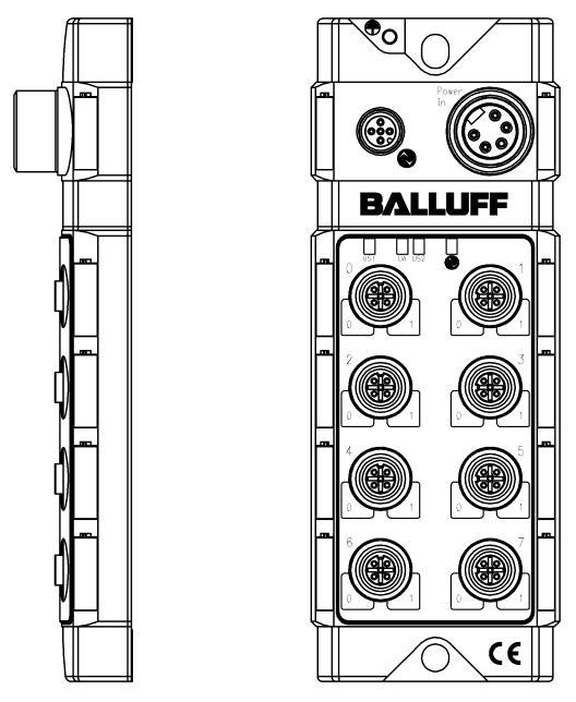
5 Balluff Network Interface / IOLink BNI IOL302xxxZ013 3 Getting started 3.1 Connection overview Figure 31: Connection overview BNI IOL302xxxZ013 1 Mounting hole 2 Label 3 Supply voltage connection 4 Status LED: communication / module 5 Standard I/O port 1 6 Standard I/O port 3 7 Standard I/O port 5 8 Standard I/O port 7 9 Mounting hole 10 Pin/Port LED: Signal status 11 Standard I/O port 6 12 Standard I/O port 4 13 Standard I/O port 2 14 Standard I/O port 0 15 Status LED: sensors/ actuators supply 16 Status LED: module supply 17 IOLink interface 18 Ground connection 4

6 Balluff Network Interface / IOLink BNI IOL302xxxZ013 3 Getting started 3.2 Mechanical connection 3.3 Electrical connection The BNI IOL302xxxZ013 modules are attached by using 2 M6 screws and 2 spacers. The BNI IOL302xxxZ013 modules require two separate supply voltage connection. The supply voltage of the module is provided through the IOLink interface by the host IOLink Master. The power for the sensors and actuators is provided by the 7/8 connector IOLink interface IOLink (M12, A coded, male) Pin Function 1 Power supply controller, +24V, max 1,1A 2 not connected 3 GND, reference potential 4 C/Q, IOLink data transmission channel 5 FE, function earth Connecting the hub Connection protection ground to FE terminal, if present. Connect sensor/actuator supply. Connect the incoming IOLink line to the hub. Note: A standard 3 wire sensor cable is used for connection to the host IOLink master. Function earth Figure 32: FE connection Note: The FE connection from the housing to the machine must be lowimpedance and kept as short as possible. Module versions Hub versions BNI IOL302000Z013 BNI IOL302S01Z013 Digital Port 16 In/ Outputs, configurable 16 In/ Outputs, configurable, with single channel monitoring Supply voltage Power In (7/8, male) connection Pin Function 1 GND, Reference potential 2 GND, Reference potential 3 FE, function earth 4 Power supply sensors, +24V 5 Power supply actuators, +24V 5
7 Balluff Network Interface / IOLink BNI IOL302xxxZ013 3 Getting started SensorActuator Standard I/O port (M12, A coded, female) interface Pin Function 1 +24V, 300mA 2 Input 2 / Output 2 3 GND 4 Input 1 / Output 1 5 FE Note! For the digital sensor inputs follow the input guideline per EN611312, type 2. Note! Unused I/Oport sockets must be fitted with cover caps to ensure IP67 protection rating. 6
8 Short circuit port 7 Short circuit port 6 Short circuit port 5 Short circuit port 4 Short circuit port 3 Short circuit port 2 Short circuit port 1 Short circuit port 0 Under voltage UA Untder voltage US2 Under voltage US1 input 6.0 Input 5.0 Input 4.0 Input 3.0 Input 2.0 Input 1.0 Input 0.0 Input 7.1 Input 6.1 Input 5.1 Input 4.1 Input 3.1 Input 2.1 Input 1.1 Input 0.1 Input 6.0 Input 6.0 Input 6.0 Input 6.0 Input 6.0 Input 6.0 Input 6.0 input 6.0 Balluff Network Interface / IOLink BNI IOL302xxxZ013 4 IOLink interface 4.1 IOLink data BNI IOL302000Z Process data / Input data Data transmission rate COM2 (38,4 kbaud) Frame type 1 Minimal cycle time 3 ms Process data cycle time 12 ms, 3 ms, at minimal cycle time Process data length 2 Bytes input, 2 Bytes output BNI IOL302S01Z013 Data transmission rate COM2 (38,4 kbaud) Frame type 1 Minimal cycle time 3 ms Process data cycle time 30 ms, at minimal cycle time Process data length 8 Bytes input, 2 Bytes output BNI IOL302000Z013 Byte 0 Byte Signal port (x): x.0: Pin 4, X.1: Pin 2 BNI IOL302S01Z013 Byte 0 Byte 1 Signal port (x): x.0: Pin 4, X.1: Pin 2 Byte 2 Byte 3 Short circuit on port x between Pin 1 and Pin 3 Short circuit Port x = 1 where x=
9 Output 7.0 Output 6.0 Output 5.0 Output 4.0 Output 3.0 Output 2.0 Output 1.0 Output 0.0 Output 7.1 Output 6.1 Output 5.1 Output 4.1 Output 3.1 Output 2.1 Output 1.1 Output 0.1 Warning port 7.0 Warning port 6.0 Warning port 5.0 Warning port 4.0 Warning port 3.0 Warning port 2.0 Warning port 1.0 Warning port 0.0 Warning port 7.1 Warning port 6.1 Warning port 5.1 Warning port 4.1 Warning port 3.1 Warning port 2.1 Warning port 1.1 Warning port 0.1 Short circuit Port 7.0 Short circuit Port 6.0 Short circuit Port 5.0 Short circuit Port 4.0 Short circuit Port 3.0 Short circuit Port 2.0 Short circuit Port 1.0 Short circuit Port 0.0 Short circuit Port 7.1 Short circuit Port 6.1 Short circuit Port 5.1 Short circuit Port 4.1 Short circuit Port 3.1 Short circuit Port 2.1 Short circuit Port 1.1 Short circuit Port 0.1 Balluff Network Interface / IOLink BNI IOL302xxxZ013 4 IOLink interface Byte 4 Byte 5 Actuator short circuit at Signal port on port x Short circuit port x.0=pin4 Short circuit port x.1=pin2 Byte 6 Byte 7 Actuator warning at signal port on port x Warning port x.0 = Pin 4 Warning port x.1 = Pin 2 Note: Actuator short circuit: overload or short circuit of the output signal against 0V. Actuator warning signal: short circuit of the output signal against +24V. 4.3 Process data / Output data BNI IOL302xxxZ013 Byte 0 Byte 1 Signal port (x): x.0: Pin 4, X.1: Pin 2 8
10 Inversion 7.0 Inversion 6.0 Inversion 5.0 Inversion 4.0 Inversion 3.0 Inversion 2.0 Inversion 1.0 Inversion 0.0 Inversion 7.1 Inversion 6.1 Inversion 5.1 Inversion 4.1 Inversion 3.1 Inversion 2.1 Inversion 1.1 Inversion 0.1 Parameter data Identification data Balluff Network Interface / IOLink BNI IOL302xxxZ013 4 IOLink interface 4.4 Parameter data / Request data DPP Index 0x07 0x08 Index SPDU Sub Index Object name Length Range Default value Vendor ID 2 Byte 0x0378 0x09 0x0A 0x0B Device ID 3 Byte 0x x x10 0 Vendor name 7 Byte BALLUFF 0x11 0 Vendor text 15 Byte read only 0x12 0 Product name 20 Byte 0x13 0 Product ID 7 Byte BNI IOL302000Z013 BNI IOL302S01Z013 BNI 0035 BNI 003A 0x14 0 Product text 22 Byte Sensor/Actor hub metal 0x16 0 Hardware Revision 1 Byte 1 0x17 0 Firmware Revision 23 Byte 1.1 0x Inversion 2 Byte 0FFFF 0x0000 0x41 0x42 0x43 0x44 0x Port direction 2 Byte 0FFFF 0x0000 Fault state Pin4 2 Byte 0FFFF 0x0000 Fault state Pin2 2 Byte 0FFFF 0x0000 Power monitoring 2 Byte 0FFFF Actuator short circuit 2Byte 0FFFF 0x Actuator warning 2 Byte 0FFFF BNI IOL302xxxZ013 Inversion Byte 0 Byte 1 Inversion port (x): x.0: Pin 4, x.1: Pin 2 Inversion 0: normal 1: inverted 9
11 Short circuit Port 7 Short circuit Port 6 Short circuit Port 5 Short circuit Port 4 Short circuit Port 3 Short circuit Port 2 Short circuit Port 1 Short circuit Port 0 Under voltage UA Under voltage US Under voltage US1 Fault state 3.1 Fault state 2.1 Fault state 1.1 Fault state 0.1 Fault state 7.1 Fault state 6.1 Fault state 5.1 Fault state 4.1 Fault state 3.0 Fault state 2.0 Fault state 1.0 Fault state 0.0 Fault state 7.0 Fault state 6.0 Fault state 5.0 Fault state 4.0 Direction 7.0 Direction 6.0 Direction 5.0 Direction 4.0 Direction 3.0 Direction 2.0 Direction 1.0 Direction 0.0 Direction 7.1 Direction 6.1 Direction 5.1 Direction 4.1 Direction 3.1 Direction 2.1 Direction 1.1 Direction 0.1 Balluff Network Interface / IOLink BNI IOL302xxxZ013 4 IOLink interface Port direction Byte 0 Byte 1 Direction port (x): x.0: pin 4, x.1: pin 2 Direction 0: Input 1: Output Fault state Pin 4 Byte 0 Byte 1 Fault state port (x) Latest state 11 Not defined Fault state Pin 2 Byte 0 Byte 1 Fault state port (x) Latest state 11 Not defined BNI IOL302000Z013 Power monitoring Byte 0 Byte 1 Short circuit on port x between pin 1 und pin 3 Short circuit port x = 1 where x=0...7 Actuator short circuit Byte 0 Byte 1 Short circuit Port 7.0 Short circuit Port 6.0 Short circuit Port 5.0 Short circuit Port 4.0 Short circuit Port 3.0 Short circuit Port 2.0 Short circuit Port 1.0 Short circuit Port 0.0 Short circuit Port 7.1 Short circuit Port 6.1 Short circuit Port 5.1 Short circuit Port 4.1 Short circuit Port 3.1 Short circuit Port 2.1 Short circuit Port Short circuit Port Actuator short circuit at signal port on port x Short circuit Port x.0=pin4 Short circuit Port x.1=pin2 10
12 Warning port 7.0 Warning port 6.0 Warning port 5.0 Warning port 4.0 Warning port 3.0 Warning port 2.0 Warning port 1.0 Warning port 0.0 Warning port 7.1 Warning port 6.1 Warning port 5.1 Warning port 4.1 Warning port 3.1 Warning port 2.1 Warning port 1.1 Warning port t 0.1 Balluff Network Interface / IOLink BNI IOL302xxxZ013 4 IOLink interface Actuator warning Byte 0 Byte 1 Actuator warning at signal port on port x Warning port x.0 = Pin 4 Warning port x.1 = Pin 2 Note: Actuator short circuit: overload or short circuit of the output signal against 0V. Actuator warning signal: short circuit of the output signal against +24V. 4.5 Error Error Code Additional Code Device application error Index not available 0x80 0x11 Device application error Subindex not available 0x80 0x12 Device application error Value out of range 0x80 0x Events Class / Qualifier Mode Type Instance Code ( high + low) Appears Error AL Device Hardware Supply Supply low voltage US1 0xC0 0x30 0x03 0x5000 0x0100 0x0010 0x0002 0xF3 0x5112 Disappears Error AL Device Hardware Supply Supply low voltage US1 0x80 0x30 0x03 0x5000 0x0100 0x0010 0x0002 0xB3 0x5112 Appears Error AL Device Hardware Supply Supply low voltage UA 0xC0 0x30 0x03 0x5000 0x0100 0x0010 0x0004 0xF3 0x5114 Disappears Error AL Device Hardware Supply Supply low voltage UA 0x80 0x30 0x03 0x5000 0x0100 0x0010 0x0004 0xB3 0x5114 Appears Error AL Device Hardware Supply Supply low voltage US2 0xC0 0x30 0x03 0x5000 0x0100 0x0010 0x0005 0xF3 0x5115 Disappears Error AL Device Hardware Supply Supply low voltage US2 0x80 0x30 0x03 0x5000 0x0100 0x0010 0x0005 0xB3 0x5115 Appears Error AL Device Hardware Supply Supply periphery 0xC0 0x30 0x03 0x5000 0x0100 0x0060 0xF3 0x5160 Disappears Error AL Device Hardware Supply Supply periphery 0x80 0x30 0x03 0x5000 0x0100 0x0060 0xB3 0x5160 Appears Error AL Device Hardware Power Output Stages 0xC0 0x30 0x03 0x5000 0x0400 0x0010 0xF3 0x5410 Disappears Error AL Device Hardware Power Output Stages 0x80 0x30 0x03 0x5000 0x0400 0x0010 0xB3 0x
13 Balluff Network Interface / IOLink BNI IOL302xxxZ013 5 Technical data 5.1 Dimensions Figure 51: Dimensions BNI IOL302xxxZ Mechanical Housing material Diecast zinc housing data IOLink port M12, A coded, male Supply voltage connection 7/8 male, 5 poles I/Oports M12, female, 5 poles Enclosure rating per IEC IP 67 (only when plugged in and threaded in) Dimensions (B x H x T in mm) 68 x 181,5 x 32,4 Weight ca. 500 gr. 5.3 Electrical data Supply voltage V DC, per EN Ripple < 1% Current draw without load <= 90 ma 5.4 Operating Operating temperature 5 C C conditions Storage temperature 25 C C EMC EN /3/4/5/6 Severity level 2B/3A/4B/2B/3A Shock/ Vibration EN , EN EN , EN

14 Balluff Network Interface / IOLink BNI IOL302xxxZ013 5 Technical data 5.5 LED indicators LED 16, Status LED Port/Pin LED: Status input / output ports Status LEDs BNI IOL302xxxZ013 Figure 52: Indication LEDs LED Indicator Function LED 1 Green / Red Supply module ok / Under voltage LED 3 Green / Red Supply actuators ok / Under voltage LED 5 Green / Red Supply sensors ok / Under voltage LED 6 Green / Green flashing Communication error / Communication ok LED I/Oports standard Indicator Function LED Pin 2 / Pin 4 Out Input signal / Output signal = 0 Yellow, static Input signal / Output signal = 1 Red Input port: KS, Short circuit Output port: Imax, Overcurrent 13
15 Balluff Network Interface / IOLink BNI IOL302xxxZ013 Appendix Product ordering code Balluff Network Interface IOLink Interface Functions 302 = 16 dig. Inputs/ Outputs Versions 000 = Standard version S01 = Single channel monitoring BNI IOL302xxxZ013 Mechanical design Z013 = Diecast zinc housing, matte nickel plated Bus connection and power supply: 1xM12 male, external thread Power supply: 1x7/8 male, external thread I/OPorts: 8xM12, female, 5poles, internal thread Order information Product ordering code Order code BNI IOL302000Z013 BNI IOL302S01Z013 BNI0035 BNI003A Scope of delivery BNI IOL consists of the following components: IOModule 4 filler plugs M12 Ground connectionband Screw M4x6 20 Labels User s guide 14
16 Nr E Issue 1008 Subject to modification Balluff Network Interface / IOLink BNI IOL302xxxZ013 Balluff GmbH Schurwaldstrasse Neuhausen a.d.f. Germany Tel Fax balluff@balluff.de
BNI IOL Z026 BNI IOL-302-S01-Z026. User s Guide
 BNI IOL302000Z026 BNI IOL302S01Z026 User s Guide Balluff Network Interface / IOLink BNI IOL302xxxZ026 1 Notes for the user 1.1 About this guide 2 1.2 Structure of the guide 2 1.3 Typographical conventions
BNI IOL Z026 BNI IOL-302-S01-Z026 User s Guide
 BNI IOL302000Z026 BNI IOL302S01Z026 User s Guide 1 Notes for the user 1.1 About this guide 2 1.2 Structure of the guide 2 1.3 Typographical conventions 2 1.3.1 Enumerations 2 1.3.2 Actions 2 1.3.3 Syntax
BNI IOL-104-S01-Z012-C02
 BNI IOL104S01Z012C01 BNI IOL104S01Z012C02 BNI IOL302S01Z013C01 User s Guide Balluff Network Interface / IOLink 1 Notes for the user 1.1 About this guide 2 1.2 Structure of the guide 2 1.3 Typographical
BNI IOL Z012. User s Guide
 BNI IOL205000Z012 User s Guide Balluff Network Interface / BNI IOL205000Z012 1 Notes for the user 1.1 About this guide 2 1.2 Structure of the guide 2 1.3 Typographical conventions 2 1.3.1 Enumerations
BNI IOL K023 BNI IOL K023. User s Guide
 BNI IOL-712-000-K023 BNI IOL-714-000-K023 User s Guide 1 Notes for the user 1.1 About this guide 2 1.2 Structure of the guide 2 1.3 Typographical conventions 2 1.3.1 Enumerations 2 1.3.2 Actions 2 1.3.3
BNI IOL Z012 BNI IOL-302-S01-Z012 BNI IOL Z042
 BNI IOL102000Z012 BNI IOL104000Z012 BNI IOL104S01Z012 BNI IOL104S01Z012C01 BNI IOL104S01Z012C02 BNI IOL302000Z012 BNI IOL302S01Z012 BNI IOL302000Z042 User s Guide Inhalt 1 Notes for the user 2 1.1. About
BNI IOL K023 BNI IOL K023. User s Guide
 BNI IOL-712-000-K023 BNI IOL-714-000-K023 User s Guide Content 1 s 2 1.1. About this guide 2 1.2. Struture of the guide 2 1.3. Typographical conventions 2 Enumerations 2 Actions 2 Syntax 2 Cross references
BNI IOL Z036 BNI IOL Z036
 BNI IOL801000Z036 BNI IOL802000Z036 Smart Light User s Guide Content 1 Notes to the user 3 1.1 About this guide 3 1.2 Structure of the guide 3 1.3 Typographical conventions 3 Enumerations 3 Actions 3 Syntax
BNI IOL K006. IO Link Sensorhub digital User s Guide
 BNI IOL-104-000-K006 BNI IOL-102-000-K006 IO Link Sensorhub digital User s Guide Content 1 Notes to the User 2 1.1. About this guide 2 1.2. Structure 2 1.3. Typographical conventions 2 Enumerations 2 Actions
BNI IOL K023 BNI IOL K023. User s Guide
 BNI IOL-712-000-K023 BNI IOL-714-000-K023 User s Guide Content 1 Notes 2 1.1. Struture of the guide 2 1.2. Typographical conventions 2 Enumerations 2 Actions 2 Syntax 2 Cross references 2 1.3. Symbols
BNI IOL K006 BNI IOL K006-C01 BNI IOL-302-S01-K006 BNI IOL-302-S01-K006-C01. IO-Link 1.1 Sensor-Hub / Actuator-Hub User s Guide
 BNI IOL302000K006 BNI IOL302000K006C01 BNI IOL302S01K006 BNI IOL302S01K006C01 IOLink 1.1 SensorHub / ActuatorHub User s Guide Content 1 Notes to the user 2 1.1 About this guide 2 1.2 Structure of the guide
BNI IOL K006 BNI IOL-106-S01-K006 BNI IOL-106-S01-K006-C01. User s Guide
 BNI IOL106000K006 BNI IOL106S01K006 BNI IOL106S01K006C01 User s Guide Content 1 Notes to the user 2 1.1 About this guide 2 1.2 Structure of the guide 2 1.3 Typographical conventions 2 Enumerations 2 Actions
BNI PBS Z001 BNI PBS Z001 BNI PBS Z001. Quick start guide
 BNI PBS-104-000-Z001 BNI PBS-102-000-Z001 BNI PBS-302-000-Z001 Quick start guide Content 1 Notes for the User 1.1 About this guide 2 1.2 Structure of the guide 2 1.3 Typografical conventions 2 1.3.1 Enumerations
BNI PNT Z015. IP67 Modules 16 Input User s Guide
 BNI PNT-104-105-Z015 IP67 Modules 16 Input User s Guide Content 1 Notes 3 1.1. About this guide 3 1.2. Structure of the guide 3 1.3. Typographical Conventions 3 Enumerations 3 Actions 3 Syntax 3 Cross-references
BNI PBS Z001 BNI PBS Z001 BNI PBS Z001 BNI PBS Z001 Short Guide
 BNI PBS-104-000-Z001 BNI PBS-302-000-Z001 BNI PBS-501-000-Z001 BNI PBS-502-000-Z001 Short Guide English 1 2 3 4 Notes to the User 3 1.1 About this guide 3 1.2 Structure of the guide 3 1.3 Typographical
BNI PNT Z015 BNI PNT Z015 BNI PNT Z015 BNI PNT Z015. IP67 Modules User s Guide
 BNI PNT-104-105-Z015 BNI PNT-202-105-Z015 BNI PNT-302-105-Z015 BNI PNT-305-105-Z015 IP67 Modules User s Guide Content 1 Notes 3 1.1. About this guide 3 1.2. Structure of the guide 3 1.3. Typographical
BNI PNT Z015. IP67 Modules 4 IO-Link/In-/Outputs,12 In-/Outputs User s Guide
 BNI PNT-502-105-Z015 IP67 Modules 4 IO-Link/In-/Outputs,12 In-/Outputs User s Guide Content 1 Notes 3 1.1. About this guide 3 1.2. Structure of the guide 3 1.3. Typographical Conventions 3 Enumerations
BNI EIP Z016. IP67 Modules, 8 Outputs BNI EIP Z016 BNI EIP Z016 IP67 Modules, 16 Outputs User s Guide
 BNI EIP-202-000-Z016 BNI EIP-202-100-Z016 IP67 Modules, 8 Outputs BNI EIP-206-000-Z016 BNI EIP-206-100-Z016 IP67 Modules, 16 Outputs User s Guide 1 Notes for the user 1.1 About this guide 2 1.2 Structure
BNI IOL Z046. IO-Link 1.1 sensor/actuator hub with extension port User's Guide
 BNI IOL302002Z046 IOLink 1.1 sensor/actuator hub with extension port User's Guide Balluff Network Interface / IOLink BNI IOL302002Z046 Contents 1 General 4 1.1. Structure of the Manual 4 1.2. Typographical
BNI IOL Z019. IO-Link 1.1 sensor hub With extension port User s Guide
 BNI IOL102002Z019 IOLink 1.1 sensor hub With extension port User s Guide Balluff Network Interface / IOLink BNI IOL102002Z019 Inhalt 1 Notes for the user 4 1.1. About this manual 4 1.2. Structure of the
BNI IOL Z046. IO-Link 1.1 Sensor hub with extension port User's Guide
 BNI IOL104002Z046 IOLink 1.1 Sensor hub with extension port User's Guide Balluff Network Interface / IOLink BNI IOL104002Z046 Contents 1 General 4 1.1. Structure of the Manual 4 1.2. Typographical Conventions
BNI PBS Z001. IP67 module, Profibus IO-Link Master Short Guide
 BNI PBS-502-001-Z001 IP67 module, Profibus IO-Link Master Short Guide 1 Notes for the User 1.1 About this guide 2 1.2 Structure of the guide 2 1.3 Typografical conventions 2 1.3.1 Enumerations 2 1.3.2
BNI IOL Z036 BNI IOL Z037. Smart Light User s Guide
 BNI IOL800000Z036 BNI IOL800000Z037 Smart Light User s Guide Content 1 Notes to the user 3 1.1 About this guide 3 1.2 Structure of the guide 3 1.3 Typographical conventions 3 Enumerations 3 Actions 3 Syntax
BNI IOL K006 BNI IOL K006-C01 BNI IOL-302-S01-K006 BNI IOL-302-S01-K006-C01. IO-Link 1.1 Sensor-Hub / Actuator-Hub User s Guide
 BNI IOL302000K006 BNI IOL302000K006C01 BNI IOL302S01K006 BNI IOL302S01K006C01 IOLink 1.1 SensorHub / ActuatorHub User s Guide Content 1 Notes to the user 3 1.1 About this guide 3 1.2 Structure of the guide
BNI DNT Z004 BNI DNT Z005 BNI DNT Z005 BNI DNT Z005 Short Guide
 BNI DNT-104-000-Z004 BNI DNT-202-000-Z005 BNI DNT-302-000-Z005 BNI DNT-305-000-Z005 Short Guide English 1 2 3 4 Notes to the User 3 1.1 About this guide 3 1.2 Structure of the guide 3 1.3 Typographical
BNI IOL Z036 BNI IOL Z037. Smart Light User s Guide
 BNI IOL802102Z036 BNI IOL802102Z037 Smart Light User s Guide Content 1 Notes to the user 3 1.1 About this guide 3 1.2 Structure of the guide 3 1.3 Typographical conventions 3 Enumerations 3 Actions 3 Syntax
BNI IOL-75x-Vxx-K007 Valve Plug Short Guide
 BNI IOL-75x-Vxx-K007 Valve Plug Short Guide Content 1 Notes to the User 2 1.1. About this guide 2 1.2. Structure 2 1.3. Typographical conventions 2 Enumerations 2 Actions 2 Syntax 2 Cross references 2
BNI IOL A027 BNI IOL A027
 BNI IOL-771-000-A027 BNI IOL-772-000-A027 IO-Link Version 1.1 Universel IO-Link Interface With undervoltage / broken coil detection User s Guide Inhalt 1 Notes to the user 2 1.1. About this guide 2 1.2.
BNI EIP Z016 IP67 Modules, 16 In-/Outputs User s Guide
 BNI EIP-302-100-Z016 IP67 Modules, 16 In-/Outputs User s Guide Balluff Network Interface EtherNet/IP, BNI EIP-302-100-Z016 1 Notes 1.1 About this guide 3 1.2 Structure of the guide 3 1.3 Typographical
BNI IOL E012. IO-Link 1.1 sensor/actuator hub with extension port User's Guide
 BNI IOL322E12 IOLink 1.1 sensor/actuator hub with extension port User's Guide Balluff Network Interface / IOLink BNI IOL322E12 Contents 1 General 4 1.1. Structure of the Manual 4 1.2. Typographical Conventions
BNI PNT Z015 BNI PNT Z015 BNI PNT Z015 BNI PNT Z015 BNI PNT Z015. IP67 Modules User s Guide
 BNI PNT-104-105-Z015 BNI PNT-202-105-Z015 BNI PNT-206-105-Z015 BNI PNT-302-105-Z015 BNI PNT-305-105-Z015 IP67 Modules User s Guide Content 1 Notes 3 1.1. About this guide 3 1.2. Structure of the guide
BNI IOL Z012. User s Guide
 BNI IOL-719-002-Z012 User s Guide Content 1 Notes for the user 3 1.1. Structure of the guide 3 1.2. Typographical Conventions 3 Enumerations 3 Actions 3 Syntax 3 Cross references 3 1.3. Symbols 3 1.4.
BNI IOL Z036 BNI IOL Z037. Smart Light User s Guide
 BNI IOL801102Z036 BNI IOL801102Z037 Smart Light User s Guide Content 1 Notes to the user 3 1.1 About this guide 3 1.2 Structure of the guide 3 1.3 Typographical conventions 3 Enumerations 3 Actions 3 Syntax
BNI USB A501. USB IO-Link Master User's Guide. english
 User's Guide english 1 2 4 Notes to the user 1.1 About this guide 1.2 Structure of the guide 1. Typographical conventions 1.4 Symbols 1.5 Abbreviations Safety 4 2.1 Intended use 4 2.2 General safety notes
BNI IOL Z036 BNI IOL Z BNI IOL Z037 BNI IOL Z Smart Light User s Guide
 BNI IOL802000Z036 BNI IOL802000Z036006 BNI IOL802000Z037 BNI IOL802000Z037006 Smart Light User s Guide Content 1 Notes to the user 3 1.1 About this guide 3 1.2 Structure of the guide 3 1.3 Typographical
BNI DNT Z001 DeviceNet IO-Link Master User s Guide
 BNI DNT-52-1-Z1 DeviceNet IO-Link Master User s Guide Contents 1 Notes 3 1.1. About this guide 3 1.2. Structure of the guide 3 1.3. Typographical conventions 3 Enumerations 3 Actions 3 Syntax 3 Cross-references
BNI IOL Z036 BNI IOL Z037. Smart Light User s Guide
 BNI IOL800000Z036 BNI IOL800000Z037 Smart Light User s Guide Content 1 Notes to the user 3 1.1 Structure of the guide 3 1.2 Typographical conventions 3 Enumerations 3 Actions 3 Syntax 3 Crossreferences
BNI USB A501. User s Guide
 BNI USB-901-013-A501 User s Guide Content 1 Notes for the user 2 1.1 About this guide 2 1.2 Structure of the guide 2 1.3 Typographical conventions 2 Enumerations 2 Actions 2 Syntax 2 Cross-references 2
BIS L x-07-S4
 BIS L-409-045-00x-07-S4 Quick Guide 41 English www.balluff.com 1 2 3 4 5 Notes to the user 5 1.1 bout this manual 5 1.2 Structure of the manual 5 1.3 Typographical conventions 5 1.4 Symbols 5 1.5 bbreviations
BNI DNT Z001. DeviceNet IO-Link Master User s Guide
 BNI DNT-52-1-Z1 DeviceNet IO-Link Master User s Guide Contents 1 Notes 3 1.1. About this guide 3 1.2. Structure of the guide 3 1.3. Typographical conventions 3 Enumerations 3 Actions 3 Syntax 3 Cross-references
BNI DNT Z001. DeviceNet IO-Link Master User s Guide
 BNI DNT-52-1-Z1 DeviceNet IO-Link Master User s Guide Contents 1 General 3 1.1. Structure of the Manual 3 1.2. Typographical conventions 3 Enumerations 3 Actions 3 Syntax 3 Cross-references 3 1.3. Symbols
BNI PNT Z015 BNI PNT Z015. IP67 Module User s Guide
 BNI PNT-502-105-Z015 BNI PNT-508-105-Z015 IP67 Module User s Guide Table of contents 1 General 3 1.1. About this manual 3 1.2. Structure of the manual 3 1.3. Typographical conventions 3 Enumerations 3
BNI EIP Z015 IP67 Modules 16 Inputs User s Guide
 BNI EIP-104-105-Z015 IP67 Modules 16 Inputs User s Guide Content 1 Notes 3 1.1. About this guide 3 1.2. tructure of the guide 3 1.3. Typographical Conventions 3 Enumerations 3 Actions 3 yntax 3 Cross-references
BIC 1B0-ITA50-Q40KFU-SM4A4A BIC 1B0-IT005-Q40KFU-SM4A4A BIC 2B0-ITA50-Q40KFU-SM4A5A. User s Guide
 BIC 1B0-ITA50-Q40KFU-SM4A4A BIC 1B0-IT005-Q40KFU-SM4A4A BIC 2B0-ITA50-Q40KFU-SM4A5A User s Guide Table of contents 1 Safety 2 1.1. Installation and startup 2 1.2. General safety instructions 2 Hazardous
BNI EIP Z015-C06. IP67 Modules 8 IO-Link/In-/Outputs, 8 In-/Outputs User s Guide
 BNI EIP-508-105-Z015-C06 IP67 Modules 8 IO-Link/In-/Outputs, 8 In-/Outputs User s Guide Content 1 Notes 3 1.1. About this guide 3 1.2. tructure of the guide 3 1.3. Typographical Conventions 3 Enumerations
BNI EIP E002. EtherNet/IP IP69 modules User's Guide
 BNI EIP-508-005-E002 EtherNet/IP IP69 modules User's Guide Table of Contents 1 General 3 1.1. Structure of the guide 3 1.2. Typographical Conventions 3 Enumerations 3 Actions 3 Syntax 3 Cross-references
Balluff Network Interface / CC-Link BNI-CCL Z001 BNI CCL Z001. Extended User Manual. 1
 BNI CCL-502-100-Z001 Extended User Manual www.balluff.com 1 1 Notes the User 1.1 About this guide 3 1.2 Structure of the guide 3 1.3 Typographical Conventions 3 1.4 Symbols 3 1.5 Abbreviations 3 2 Safety
BNI PNT Z015 BNI006C. IP67 Module User s Guide
 BNI PNT-502-102-Z015 BNI006C IP67 Module User s Guide Table of contents 1 General 4 1.1. About this manual 4 1.2. Structure of the manual 4 1.3. Typographical conventions 4 Enumerations 4 Actions 4 Syntax
BNI EIP Z015. IP67 Modules 8 IO-Link/In-/Outputs, 8 In-/Outputs User s Guide
 BNI EIP-508-105-Z015 IP67 Modules 8 IO-Link/In-/Outputs, 8 In-/Outputs User s Guide Content 1 Notes 3 1.1. About this guide 3 1.2. tructure of the guide 3 1.3. Typographical Conventions 3 Enumerations
BNI CCL Z001. CC-Link IO-Link Master User s Guide
 BNI CCL-502-100-Z001 CC-Link IO-Link Master User s Guide Table of Contents 1 Notes for the user 3 1.1. Conformity and user safety 3 1.2. About this guide 3 1.3. Structure of the guide 3 1.4. Typographical
BNI EIP Z040. IP67 Module 4 IO-Link Class A and 8 in- and outputs 4 IO-Link Class B and 4 inputs User's Guide
 BNI EIP-507-005-Z040 BNI EIP-527-005-Z040 IP67 Module 4 IO-Link Class A and 8 in- and outputs 4 IO-Link Class B and 4 inputs User's Guide Table of Contents 1 General 3 1.1. Structure of the manual 3 1.2.
BNI DNT Z004 BNI DNT Z005 BNI DNT Z005 BNI DNT Z005 BNI DNT Z005. User s Guide
 BNI DNT-104-000-Z004 BNI DNT-202-000-Z005 BNI DNT-302-000-Z005 BNI DNT-305-000-Z005 BNI DNT-305-007-Z005 User s Guide Contents 1 User instructions 3 1.1. Structure of the guide 3 1.2. Typographical conventions
BNI PNT Z031 BNI PNT Z IP67 Module User s Guide
 BNI PNT-508-105-Z031 BNI PNT-508-105-Z031-002 BNI PNT-508-105-Z031-004 IP67 Module User s Guide Table of contents 1 General 4 1.1. About this manual 4 1.2. Structure of the manual 4 1.3. Typographical
BNI EIP Z015 BNI EIP Z015. EtherNet/IP IP67 modules User's Guide
 BNI EIP-502-105-Z015 BNI EIP-508-105-Z015 EtherNet/IP IP67 modules User's Guide Table of Contents 1 Notes 3 1.1. Structure of the guide 3 1.2. Typographical Conventions 3 Enumerations 3 Actions 3 Syntax
BNI PNT Z015 BNI PNT Z015. IP67 Module User s Guide
 BNI PNT-502-105-Z015 BNI PNT-508-105-Z015 IP67 Module User s Guide Table of contents 1 General 4 1.1. Structure of the manual 4 1.2. Typographical conventions 4 Enumerations 4 Actions 4 Syntax 4 Cross-references
BNI CIE Z015 BNI CIE Z015 BNI CIE Z015 BNI CIE Z015. CC-Link IE Field Standard I/O Modules User's Guide
 BNI CIE-104-105-Z015 BNI CIE-106-105-Z015 BNI CIE-302-105-Z015 BNI CIE-311-105-Z015 CC-Link IE Field Standard I/O Modules User's Guide Contents 1 Notes to the user 3 1.1. About this guide 3 1.2. Structure
BNI EIP R015 BNI EIP R015. EtherNet/IP IP67 modules User's Guide
 BNI EIP-502-105-R015 BNI EIP-508-105-R015 EtherNet/IP IP67 modules User's Guide Table of Contents 1 Notes 3 1.1. About this guide 3 1.2. tructure of the guide 3 1.3. Typographical Conventions 3 Enumerations
GFK-2415A March Type of sensor connection
 VersaMax IP Expansion Module has four analog differential inputs that can be configured as current or voltage inputs. It connects to a local bus that is interfaced to a Profibus-DP / PROFINET network by
BNI PNT Z015 BNI PNT Z015 BNI PNT Z015 BNI PNT Z015 BNI PNT Z015. IP67 Modules User s Guide
 BNI PNT-104-105-Z015 BNI PNT-202-105-Z015 BNI PNT-206-105-Z015 BNI PNT-302-105-Z015 BNI PNT-305-105-Z015 IP67 Modules User s Guide Content 1 Notes 3 1.1. Structure of the guide 3 1.2. Typographical Conventions
VersaMax IP I/O Module
 Module accepts four digital input signals and provides four digital outputs. It connects to a local bus that is interfaced to a Profibus-DP / PROFINET network by a Profibus Interface Unit (IC677PBI001)
BNI PBS Z001 BNI PBS Z001 BNI PBS Z001 BNI PBS Z001. Profibus IO Modules User's Guide
 BNI PBS-104-101-Z001 BNI PBS-202-101-Z001 BNI PBS-206-101-Z001 BNI PBS-302-101-Z001 Profibus IO Modules User's Guide Contents 1 Notes for the user 3 1.1 About this manual 3 1.2 Structure of the manual
Balluff smart safety BE ON THE SAFE SIDE. SAFETY OVER IO-LINK
 Balluff smart safety BE ON THE SAFE SIDE. SAFETY OVER IO-LINK 2 Balluff smart safety Simply safe SMART SAFETY. SAFETY WITH BALLUFF QUALITY. Balluff smart safety 3 Safety over IO-Link bridges the gap between
BIS L x-07-S4
 BIS L-409-045-00x-07-S4 Technical Description, User's Guide 41 English www.balluff.com 1 2 3 4 5 6 7 8 Notes to the user 5 1.1 bout this manual 5 1.2 Structure of the manual 5 1.3 Typographical conventions
BNI CIE Z015 BNI CIE Z015. CC-Link IE Field IO-Link Master User's Guide
 BNI CIE-508-105-Z015 BNI CIE-518-105-Z015 CC-Link IE Field IO-Link Master User's Guide Contents 1 General 3 1.1. Structure of the guide 3 1.2. Typographical Conventions 3 Enumerations 3 Actions 3 Syntax
BIS M _ 0 _ -07-S4 BIS M _ 0 _ -07-S4
 BIS M-4-045- _ 0 _ -07-S4 BIS M-4-072- _ 0 _ -07-S4 Technical Description, Operating Manual english www.balluff.com 1 User Instructions 5 1.1 Conformity and User Safety 5 1.2 Scope of Delivery 5 1.3 About
BNI EIP Z015 BNI EIP Z015 BNI EIP Z015. EtherNet/IP IP67 Modules User s Guide
 BNI EIP-104-105-Z015 BNI EIP-202-105-Z015 BNI EIP-302-105-Z015 EtherNet/IP IP67 Modules User s Guide Content 1 Notes 3 1.1. tructure of the guide 3 1.2. Typographical Conventions 3 Enumerations 3 Actions
BNI CCL Z001. CC-Link IO-Link Master User s Guide
 BNI CCL-502-100-Z001 CC-Link IO-Link Master User s Guide Table of Contents 1 Notes 3 1.1. Conformity and user safety 3 1.2. Structure of the guide 3 1.3. Typographical conventions 3 Enumerations 3 Actions
VersaMax IP Input Module
 Module is used to accept digital input signals. Module Specifications Housing dimensions (width x height x depth) Connection style Operating temperature Storage temperature Operating/storage humidity 60mm
BIS V-6102 PROFIBUS. Technical Description, User s Guide. english 42,7 61,9 5,3 168,3 +6,0 157,6 +6,0 36,4 2,5 48,2
 Technical Description, User s Guide 42,7 61,9 5,3 36,4 168,3 +6,0 157,6 +6,0 4 2,5 48,2 31 english www.balluff.com 1 User Instructions 4 1.1 About this Manual 4 1.2 Typographical Conventions 4 1.3 Symbols
BIS L , BIS Z-EL-...
 BIS L-400-..., BIS Z-EL-... Technical Description, User's Guide English www.balluff.com 1 2 3 4 5 6 7 8 9 Notes to the user 4 1.1 About this manual 4 1.2 Structure of the manual 4 1.3 Typographical conventions
User's Manual. english
 BES M12EN-PFC40F-S04G-D11 BES M18EN-PFC80F-S04G-D11 BES M18MN-PFC50B-S04G-D11 BES M30EN-PFC15F-S04G-D11 BES M30MN-PFC10B-S04G-D11 Inductive Safety Sensors User's Manual english www.balluff.com Original
BIS M _ -07-S4 BIS M _ -07-S4
 BIS M-4-045-00 _ -07-S4 BIS M-4-072-00 _ -07-S4 Technical Description, Operating Manual English www.balluff.com 1 2 3 4 5 6 7 8 User instructions 5 1.1 Conformity and user safety 5 1.2 Scope of delivery
BTL6-V1 _ E-M -A1-S115 User's Guide
 User's Guide BTL1035 BTL6 V11E M0500 A1 S115 english www.balluff.com 1 Notes to the user 4 1.1 Validity 4 1.2 Symbols and conventions 4 1.3 Scope of delivery 4 1.4 Approvals and markings 4 1.5 Abbreviations
AXL E IOL AO1 U M12 R
 Axioline E IO-Link/analog converter for connecting an analog actuator, 0 V... 10 V, rectangular version Data sheet 8588_en_03 PHOENIX CONTACT 2014-09-22 1 Description The IO-Link/analog converter is an
BNI EIP Z015-C06. EtherNet/IP IP67 modules User's Guide
 BNI EIP-508-105-Z015-C06 EtherNet/IP IP67 modules User's Guide Table of Contents 1 Notes 3 1.1. tructure of the guide 3 1.2. Typographical Conventions 3 Enumerations 3 Actions 3 yntax 3 Cross-references
SK TU4-IOE-M12-C Part Number
 SK TU4-IOE-M2-C Part Number 275 28 256 IO Extension Only qualified electricians are allowed to install and commission the module described below. An electrician is a person who, because of their technical
BIS V-6102 Profibus. Technical Description, User's Guide. English 42,7 61,9 5,3 168,3 +6,0 157,6 +6,0 36,4 2,5 48,2
 Technical Description, User's Guide 42,7 61,9 5,3 36,4 168,3 +6,0 157,6 +6,0 4 2,5 48,2 31 English www.balluff.com 1 2 3 4 5 6 7 8 User instructions 4 1.1 About this manual 4 1.2 Typographical conventions
Profibus I/O Modules BNI PBS Z001 BNI PBS Z001
 Profibus I/O Modules BNI PBS-104-000-Z001 BNI PBS-302-000-Z001 User's Guide 36.9 68.0 english www.balluff.com Balluff Network Interface / I/O Profibus Modules 1 2 3 4 5 6 7 8 Notes to the user 4 1.1 About
BIS M x-ST4 EtherNet/IP
 Technical Description, Operating Manual English www.balluff.com 1 User Instructions 4 1.1 About this Manual 4 1.2 Typographical Conventions 4 1.3 Symbols 4 1.4 Meaning of Warning Notes 4 1.5 Abbreviations
BIS M xx-ST4 PROFINET
 Technical Description, Operating Manual english www.balluff.com 1 User Instructions 4 1.1 About this Manual 4 1.2 Typographical Conventions 4 1.3 Symbols 4 1.4 Abbreviations 5 2 Safety 6 2.1 Intended use
BTL6-V11V-M -A1-S115 User's Guide
 User's Guide english www.balluff.com 1 Notes to the user 4 1.1 Validity 4 1.2 Symbols and conventions 4 1.3 Scope of delivery 4 1.4 Approvals and markings 4 1.5 Abbreviations 4 2 Safety 5 2.1 Intended
BTL6-A_10-M -A1-S115. Data Sheet. english
 BT6-A_10-M -A1-S11 english Data Sheet Balluff GmbH Schurwaldstrasse 9 76 Neuhausen a.d.f. Germany Phone +49 (0) 71 8/1-0 Fax +49 (0) 71 8/0 10 Servicehotline +49 (0) 71 8/1-70 E-Mail: balluff@balluff.de
Pressure Transmitters with IO-Link BSP-Bxxx-xx004-xxxS1A-xx, BSP-Vxxx-xx004-xxxS1A-xx
 EU Directive 2004/108/EC (EMC Directive) and EMC Law Generic Standards: EN 61000-6-4 (Emissions), EN 61000-6-2 (Interference Immunity) Emissions testing: Radio interference emissions EN 55011 Group 1,
FLM DI 8 M12. Function. Fieldline Modular Device With Eight Digital Inputs. Data Sheet
 Fieldline Modular Device With Eight Digital Inputs Data Sheet 697000 02/2004 This data sheet is only valid in association with the FLS FLM SYS INST UM E user manual or the user manual for your bus system
Manual LioN-P - IO-Link Device - I/O Hub
 Manual LioN-P - IO-Link Device - I/O Hub 0960 IOL 381-001 0960 IOL 385-001 0960 IOL 380-021 Technical Support support-automation@belden.com Contents Contents 1 About this Manual 6 1.1 General Information
AS-i / IO-Link Module, IO-Link Master with 4 IO-Link Ports
 / IO-Link Module, /IO-Link Module, IO-Link Master with 4 s fourfold IO-Link Master in one housing Power supply of s (or ) (Figure similar) Figure Type Inputs digital 4 x + 4 x + 4 x Outputs digital M12
Operating instructions ClassicLine module AC / / 2012
 Operating instructions ClassicLine module AC0 UK 79079 / 0 06 / 0 Contents Safety instructions... Functions and features... Operating and display elements... Installation... Addressing... 9. Addressing
Operating instructions. ProcessLine analogue module AC / / 2012
 Operating instructions ProcessLine analogue module AC2916 739089 / 01 06 / 2012 Contents 1 Safety instructions... 3 2 Functions and features... 4 3 Operating and display elements... 4 4 Electrical connection...
BNI PNT Z063. IP67 Module User's Guide
 BNI PNT-538-105-Z063 IP67 Module User's Guide Table of Contents 1 General 4 1.1. Structure of the guide 4 1.2. Typographical Conventions 4 Enumerations 4 Actions 4 Syntax 4 Cross-references 4 1.3. Symbols
BNI PNT Z015 BNI PNT Z015. IP67 Module User s Guide
 BNI PNT-502-105-Z015 BNI PNT-508-105-Z015 IP67 Module User s Guide Table of contents 1 General 4 1.1. Structure of the manual 4 1.2. Typographical conventions 4 Enumerations 4 Actions 4 Syntax 4 Cross-references
MANUAL VAA-2E2A-G12-SAJ/EA2L Original Instructions Version 1.0
 FACTORY AUTOMATION MANUAL VAA-2E2A-G12-SAJ/EA2L Original Instructions Version 1.0 SAFETY AT WORK With regard to the supply of products, the current issue of the following document is applicable: The General
BTL5-A/C/E1_-M- -SF-F User's Guide
 BTL5-A/C/E1_-M- -SF-F User's Guide english www.balluff.com 1 Notes to the user 1.1 Validity 1.2 Symbols and conventions 1.3 Scope of delivery 1. Approvals and markings 1.5 Abbreviations 2 Safety 5 2.1
Operating instructions AC010S Compact AS-i E-STOP safety module
 Operating instructions AC010S Compact AS-i E-STOP safety module Sachnr. 7390636_/00 05/2007 Contents Safety instructions............................. 3 Installation / Setup............................
BIS V-6111 CC-Link Technical Description, User s Guide
 Technical Description, User s Guide english www.balluff.com 1 User Instructions 4 1.1 About this Manual 4 1.2 Typographical Conventions 4 1.3 Symbols 4 1.4 Abbreviations 4 2 Safety 5 2.1 Intended Use 5
BIS V-6108 PROFINET. Technical Description, User s Guide. english
 Technical Description, User s Guide english www.balluff.com 1 User Instructions 4 1.1 About This Manual 4 1.2 Typographical Conventions 4 1.3 Symbols 4 1.4 Abbreviations 5 2 Safety 6 2.1 Intended Use 6
Operating instructions Memory plug E /02 11/2011
 Operating instructions Memory plug E30398 UK 704930/02 11/2011 Contents 1 Preliminary note...3 1.1 Symbols used...3 1.2 Terms used...3 2 Safety instructions...4 3 Factory setting...4 4 Functions and features...5
Operating instructions RFID evaluation unit DTE / / 2016
 Operating instructions RFID evaluation unit DTE101 80005398 / 01 06 / 2016 Contents 1 Preliminary note...4 1.1 Notes on this document...4 1.2 Symbols used...4 2 Safety instructions...4 2.1 General...4
CPCI-PS24 24V-Power Supply
 24V-Power Supply Hardware Manual to Product I.2301.21 esd electronic system design gmbh Vahrenwalder Str. 207 30165 Hannover Germany http://www.esd.eu Phone: +49 (0) 511 3 72 98-0 Fax: +49 (0) 511 3 72
Manual ICA-16DI-G60A-IO, ICA-10DI6DO-G60A-IO. I/O Hub with IO-Link
 Manual ICA-16DI-G60A-IO, ICA-10DI6DO-G60A-IO I/O Hub with IO-Link The latest version of the General Terms of Supply for Products and Services in the Electronics Industry set out by the German Electrical
Operating instructions AS-i SmartLine module AC3200 AC /00 06/2016
 Operating instructions AS-i SmartLine module AC3200 AC3201 80237876/00 06/2016 Contents 1 Preliminary note...3 1.1 Symbols used...3 1.2 Warnings used...3 2 Safety instructions...3 2.1 General...3 2.2 Target