1690-Series Logic Analyzers
|
|
|
- Frank McBride
- 6 years ago
- Views:
Transcription
1 1690-Series Logic Analyzers Quick Start/Installation Installation 2 Making a measurement 4 Snap to Edge Markers 6 Left-Click Menus 7 Tree Structure Labels 7 Offline Analysis 8 Marker Overview 8 Tool Tips 8 Trigger History 9 Probing 10 Proper Cooling 10 Self-Test 11 Software Installation and Upgrades 12 Specifications and Characteristics 13 Safety Notices 15 Agilent Technologies

2 Installation You will need to install an Agilent E5851A IEEE 1394 card and the Agilent Logic Analyzer application software on your PC. PC System Requirements: 1.0 GHz minimum, Intel Pentium 3, AMD Athlon K7 or better. 512M RAM. Windows 2000 Professional or Windows XP Professional installed. 100M minimum available hard disk space. Windows XP will not prompt you if the IEEE 1394 card is not properly installed. Follow the instructions that came with the Agilent E5851A IEEE 1394 Connection Kit and your PC s documentation to: Install the IEEE 1394 card in any available slot in your PC. Load logic analyzer application software. Connect the logic analyzer to your PC. Install ferrite to ensure radio frequency interference compliance. Refer to the online help in the logic analyzer for information on using the analyzer Series Quick Start/Installation
3 Snap the accessories pouch to the top of the 1690-series logic analyzer. Use it to store probe leads, accessories, or manuals. Use the tie-down straps under the flap to conveniently hold pod cables not in use or during transport. Accessories Pouch (top flap) Pod Cables Tie-down Straps Snaps (4) 1690-Series Quick Start/Installation 3


4 Making a measurement 1 Start up the logic analyzer, connect to your target system, and select Setup>Bus/Signal. 2 Assign buses and signals and click OK Series Quick Start/Installation


5 3 Enter a trigger value. 4 Acquire and view data Series Quick Start/Installation 5


6 Snap to Edge Markers You can set the markers to jump to the nearest edge of a waveform. A yellow target will show which edge the marker will jump to Series Quick Start/Installation


7 Left-Click Menus Drag a box around parts of the data. When you release the mouse button, a menu appears. Tree Structure Labels Show individual signals in buses by clicking on the + to expand Series Quick Start/Installation 7

8 Offline Analysis Marker Overview Install the Agilent Logic Analyzer application on another Windows XP or Windows 2000 computer and you can analyze data without the 1690-series logic analyzer. 1 Follow the instructions in Software Installation and Upgrades" on page 12 to load the 1690-series logic analyzer software on your PC. 2 Acquire a trace with the logic analyzer. 3 Save a configuration file with data. 4 Copy the file to the PC being used for offline analysis. 5 From the Agilent Logic Analyzer application software on your PC, open the configuration file. The marker overview display shows marker locations within the data and the part of data currently being displayed. Tool Tips Pause the cursor over a tool Icon and a Tool Tip Window will appear Series Quick Start/Installation


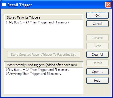
9 Trigger History Save and recall trigger settings Series Quick Start/Installation 9
10 Probing Proper Cooling Probing is the key to effective and efficient use of logic analyzers. Agilent Technologies offers a wide variety of probing accessories that support general-purpose and application-specific measurement needs. We provide reliable, electrically and mechanically unobtrusive probes that make it easy to connect your Agilent logic analyzer to your system under test. For more information on Agilent probes: See the quick reference card that came with your logic analysis system for an overview of probing solutions. Go to for the most up-to-date information on probe compatibility with a given logic analyzer and purchasing information. Go to and search for Probing Solutions for Logic Analyzers (publication E) for a catalog of detailed probing information. To connect and set up a probe, follow the instructions in the User s Guide that came with the probe. Allow at least 5 cm (2 inches) of space between instruments for proper cooling. 5 cm (2 inches) 5 cm (2 inches) Series Quick Start/Installation


11 Self-Test To run self-tests go to Help>Self Test and then select the desired test Series Quick Start/Installation 11


12 Software Installation and Upgrades To install the Agilent Logic Analyzer application, insert the application software CD into the PC s CD drive. Follow the steps in the Install Wizard Series Quick Start/Installation
13 Installing the logic analyzer application on another Windows XP or Windows 2000 computer allows you to analyze data without the logic analyzer. Logic analyzer product CDs can be ordered from this web-site: To be notified when software upgrades are available for downloading from the web, please sign up for notifications at: Specifications and Characteristics The following electrical and operating characteristics are not specifications, but are typical operating characteristics for the Agilent 1690-series logic analyzers. Electrical Characteristics Power Requirements Ferrites Frame: 115/230 Vac +/- 20%, 48-66Hz, 610W Max CAT II (Line voltage in appliance and to wall outlet) Pollution degree 2 In order to ensure compliance of the Agilent 1680-series logic analyzers to the CISPR 11 Class A radio frequency interference (RFI) limits, you must install the ferrite to absorb radio frequency energy. Adding or removing ferrites will not affect the normal operation of the analyzer. Environmental Characteristics (Operating) Temperature Instrument: 0 to + 50 C (+32 to +122 F) Disk Media: 10 to + 40 C (+50 to +104 F) Probes/cables: 0 to + 65 C (+32 to +149 F) Altitude Humidity 3,000 m (10,000 ft) Relative humidity 8 to 80% at 40 C (104 F). Avoid sudden, extreme temperature changes which could cause condensation on the circuit board. For indoor use only Series Quick Start/Installation 13


14 More specifications and characteristics for your instrument and measurement modules are in the on-line help. To find them go to: 1 Click Help>Help Topics. 2 Click Reference>Specifications and Characteristics Series Quick Start/Installation
15 Safety Notices This apparatus has been designed and tested in accordance with IEC Publication 1010, Safety Requirements for Measuring Apparatus, and has been supplied in a safe condition. This is a Safety Class I instrument (provided with terminal for protective earthing). Before applying power, verify that the correct safety precautions are taken (see the following warnings). In addition, note the external markings on the instrument that are described under "Safety Symbols." Warnings Before turning on the instrument, you must connect the protective earth terminal of the instrument to the protective conductor of the (mains) power cord. The mains plug shall only be inserted in a socket outlet provided with a protective earth contact. You must not negate the protective action by using an extension cord (power cable) without a protective conductor (grounding). Grounding one conductor of a two-conductor outlet is not sufficient protection. Only fuses with the required rated current, voltage, and specified type (normal blow, time delay, etc.) should be used. Do not use repaired fuses or short-circuited fuse holders. To do so could cause a shock or fire hazard. If you energize this instrument by an auto transformer (for voltage reduction or mains isolation), the common terminal must be connected to the earth terminal of the power source. Whenever it is likely that the ground protection is impaired, you must make the instrument inoperative and secure it against any unintended operation. Service instructions are for trained service personnel. To avoid dangerous electric shock, do not perform any service unless qualified to do so. Do not attempt internal service or adjustment unless another person, capable of rendering first aid and resuscitation, is present. Do not install substitute parts or perform any unauthorized modification to the instrument. Capacitors inside the instrument may retain a charge even if the instrument is disconnected from its source of supply Series Quick Start/Installation 15
16 Do not operate the instrument in the presence of flammable gasses or fumes. Operation of any electrical instrument in such an environment constitutes a definite safety hazard. Do not use the instrument in a manner not specified by the manufacturer. To optimize your comfort and productivity, it is important that you set up your work area correctly and use your equipment properly. Refer to for set-up and use recommendations Position equipment so that it is not difficult to disconnect the power cord. To clean the instrument If the instrument requires cleaning: 1 Remove power from the instrument. 2 Clean the external surfaces of the instrument with a soft cloth dampened with a mixture of mild detergent and water. 3 Make sure that the instrument is completely dry before reconnecting it to a power source. Safety Symbols! Instruction manual symbol: the product is marked with this symbol when it is necessary for you to refer to the instruction manual in order to protect against damage to the product. Hazardous voltage symbol. Earth terminal symbol: Used to indicate a circuit common connected to grounded chassis. Agilent Technologies, Inc Printed in Malaysia March 2004 * * Manual part number Agilent Technologies
1680-Series Logic Analyzers
 1680-Series Logic Analyzers Quick Start/Installation Product Overview 2 First-Time Power Up Considerations 4 Answering Windows Welcome Questions 6 Additional First-Time Setup Steps 8 Making a Measurement
Agilent Technologies E5385A 100-Pin Probe
 Agilent Technologies E5385A 100-Pin Probe Installation Note The Agilent Technologies E5385A 100-pin probe provides a convenient way to connect two Agilent Technologies logic analyzer probe cables to a
Agilent Technologies E5346A 38-Pin Probe and E5351A 38-Pin Adapter Cable
 Agilent Technologies E5346A 38-Pin Probe and E5351A 38-Pin Adapter Cable Installation Note The 38-pin probe and adapter cable provide a convenient way to connect two Agilent Technologies logic analyzer
Quick Start/Installation Guide
 Agilent Technologies E5850A Time Correlation Fixture Quick Start/Installation Guide The Agilent E5850A time correlation fixture allows you to make time-correlated measurements between a 1680/90 or 16700
Agilent Technologies E5339A 38-Pin Low-Voltage Probe
 Agilent Technologies E5339A 38-Pin Low-Voltage Probe Installation Note The 38-pin low-voltage probe provides a convenient way to connect two Agilent Technologies logic analyzer probe cables to a small
Agilent N4219B Packet Analysis Probe for Serial ATA. User s Guide
 Agilent N4219B Packet Analysis Probe for Serial ATA User s Guide A Notices Agilent Technologies, Inc. 2002-2005 No part of this manual may be reproduced in any form or by any means (including electronic
Agilent W2630 Series DDR2 DRAM BGA Probe User s Guide
 Agilent W2630 Series DDR2 DRAM BGA Probe User s Guide Introduction This User's Guide provides operation information for the W2630 series DDR2 DRAM BGA probe. This information also applies to the E5384A
Agilent 34401A 6½ 桁マルチメータ ユーザーガイド
 Agilent 34401A 6½ 桁マルチメータ ユーザーガイド Safety Information General Do not use this product in any manner not specified by the manufacturer. The protective features of this product may be impaired if it is used
Agilent Series Portable Logic Analyzers
 Agilent 16800 Series Portable Logic Analyzers Installation/Quick Start Guide REPRODUCTION AND DISTRIBUTION OF THIS TECHNICAL MANUAL IS AUTHORIZED FOR GOVERNMENT PURPOSES. Agilent Technologies Notices Agilent
Model 2380 Rack-Mount Kit
 Keithley Instruments 28775 Aurora Road Cleveland, Ohio 44139 1-800-935-5595 http://www.tek.com/keithley Model 2380 Rack-Mount Kit Installation Instructions Introduction The Model 2380 Fixed Rack-Mount
Model P4017 Single Channel USB Oscilloscope. Quick Start Guide
 Model P4017 Single Channel USB Oscilloscope Quick Start Guide General Warranty BNC warrants that the product will be free from defects in materials and workmanship for 3 years from the date of purchase
Advanced Test Equipment Rentals ATEC (2832)
") Established 1981 Advanced Test Equipment Rentals www.atecorp.com 800-404-ATEC (2832) User s Guide Publication number E2625-97003 March 2002 For Safety information and Regulatory information, see the pages
Established 1981 Advanced Test Equipment Rentals www.atecorp.com 800-404-ATEC (2832) User s Guide Publication number E2625-97003 March 2002 For Safety information and Regulatory information, see the pages
HV-CS kv Edge Mount Triaxial Jack
 Keithley Instruments 28775 Aurora Road Cleveland, Ohio 44139 1-800-935-5595 http://www.tek.com/keithley HV-CS-1589 3 kv Edge Mount Triaxial Jack Installation Information Description The Keithley Instruments
RZ5/RZ5D/RZ6 Processor. Operator s Manual
 RZ5/RZ5D/RZ6 Processor Operator s Manual RZ5/RZ5D/RZ6 Processor Operator s Manual Copyright 2010-2013 Tucker-Davis Technologies, Inc. (TDT). All rights reserved. No part of this manual may be reproduced
Keysight E5864A Removable Hard Drive for Series Logic Analyzers. Installation Guide
 Keysight E5864A Removable Hard Drive for 16850-Series Logic Analyzers Installation Guide Notices Keysight Technologies 2013-2014 No part of this manual may be reproduced in any form or by any means (including
Model 2460-KIT. Screw Terminal Connector Kit. Description / September 2014 *P * 1
 Keithley Instruments 28775 Aurora Road Cleveland, Ohio 44139 1-800-935-5595 http://www.keithley.com Model 2460-KIT Screw Terminal Connector Kit Description The Model 2460-KIT Screw Terminal Connector Kit
RZ2 BioAmp Processor. Operator s Manual
 RZ2 BioAmp Processor Operator s Manual RZ2 BioAmp Processor Operator s Manual Copyright 2008-2013 Tucker-Davis Technologies, Inc. (TDT). All rights reserved. No part of this manual may be reproduced or
1-36V, 0-3A DC Power Supply
 1550 1-36V, 0-3A DC Power Supply User Manual Safety Summary The following safety precautions apply to both operating and maintenance personnel and must be followed during all phases of operation, service,
Getting Started with the Agilent Serial BERT N4906B. You only need a few minutes to get started with the Serial BERT.
 Getting Started with the Agilent Serial BERT N4906B You only need a few minutes to get started with the Serial BERT. This Getting Started Brochure helps you to quickly understand the operating principles
Agilent U4154A Logic Analyzer
 Agilent U4154A Logic Analyzer Service Guide Agilent Technologies Notices Agilent Technologies, Inc. 2013 No part of this manual may be reproduced in any form or by any means (including electronic storage
Model 2380 Rack-Mount Kit
 Keithley Instruments 28775 Aurora Road Cleveland, Ohio 44139 1-800-935-5595 http://www.tek.com/keithley Model 2380 Rack-Mount Kit Installation Instructions Introduction The Model 2380 Fixed Rack-Mount
Simple Logger II Series
 Simple Logger II Series Quick Start Guide ENGLISH www.aemc.com CHAUVIN ARNOUX GROUP Statement of Compliance Chauvin Arnoux, Inc. d.b.a. AEMC Instruments certifies that this instrument has been calibrated
Agilent 70612B K18 Switch Matrix
 Agilent 70612B K18 Switch Matrix Hardware Reference Manual Agilent Technologies COPYRIGHT 2000 AGILENT TECHNOLOGIES, INC. ALL RIGHTS RESERVED. NO PART OF THIS DOCUMENT MAY BE REPRODUCED IN ANY FORM OR
Controller Specifications
 INRODUCTION Chromium Controller Specifications FOR USE WITH Chromium Controller & Accessory Kit PN-120223 NOTICES Notices Manual Part Number CG00020 Rev B Legal Notices 2017 10x Genomics, Inc. All rights
DC POWER SUPPLY. Model: PW-3063R / PW-4063R
 DC POWER SUPPLY INSTRUCTION MANUAL Model: PW-3063R / PW-4063R Table of Contents: Notice Before Operation Maintenance General Maintenance Panel Description 1. Symbol Description 2. Front Panel Description
User s Manual Power Supply IM E. 5th Edition
 User s Manual 701934 Power Supply 5th Edition Thank you for purchasing the 701934 Power Supply. This user s manual contains useful information about the functions and operating procedures of the 701934
ATS-16 HV USER MANUAL. Automatic Transfer Switch 16A / 230Vac V090318
 ATS-16 HV Automatic Transfer Switch 16A / 230Vac USER MANUAL V090318 SAFETY Intended use The ATS-16 HV device serves as a power source selector to provide improved power supply for connected loads. ATS-16
OWNER S MANUAL 9908-TE. HIGH PRECISION AUTO-RANGING DC/True RMS AC BENCH-TOP DIGITAL MULTIMETER
 OWNER S MANUAL 9908-TE HIGH PRECISION AUTO-RANGING DC/True RMS AC BENCH-TOP DIGITAL MULTIMETER IMPORTANT! Read and understand this manual before using the instrument. Failure to understand and comply with
HP E2485A. Installation Guide. Memory Expansion Interface. Copyright Hewlett-Packard Company 1997 All Rights Reserved
 Installation Guide Copyright Hewlett-Packard Company 1997 All Rights Reserved For Safety Information, Warranties, and Regulatory information, see the pages at the back of this book. Publication Number
EOS-6000 Series Optical A/B Switch User Manual DC Version
 EOS-6000 Series Optical A/B Switch User Manual DC Version For more information on this and other products: Contact Sales at EMCORE 626-293-3400, or visit www.emcore.com. Table of Contents Table of Contents...2
User s Guide. Agilent Technologies Probes for the 16760A Logic Analyzer (E5378A, E5379A, E5380A, and E5386A)
") User s Guide Publication number 16760-97007 February, 2002 For Safety information, Warranties, and Regulatory information, see the pages behind the index. Copyright Agilent Technologies 2000-2002 All Rights
User s Guide Publication number 16760-97007 February, 2002 For Safety information, Warranties, and Regulatory information, see the pages behind the index. Copyright Agilent Technologies 2000-2002 All Rights
SLA Battery Capacity Analyzer
 Model: 601B SLA Battery Capacity Analyzer USER MANUAL Safety Summary The following safety precautions apply to both operating and maintenance personnel and must be followed during all phases of operation,
* * Agilent Power Distribution Unit (PDU) Installation Guide
 Installation Guide") Agilent Power Distribution Unit (PDU) Installation Guide For use with Agilent PDU kits and PDU installation kits for Agilent instrument racks June 2008 Edition 7 E0608 *5000-0039* 5000-0039 Notice The
Agilent Power Distribution Unit (PDU) Installation Guide For use with Agilent PDU kits and PDU installation kits for Agilent instrument racks June 2008 Edition 7 E0608 *5000-0039* 5000-0039 Notice The
MC-12 Software Installation Instructions
 MC-12 DOCUMENTATION CONVENTIONS This document contains software installation instructions for the MC-12/MC-12 Balanced. Refer to the MC-12 User Guide for general safety, installation, and operating instructions.
Model 4200-CVU-PWR. Parts Package. Introduction. PA-977 Rev. C / September 2016 *PPA-977C* 1
 Keithley Instruments 28775 Aurora Road Cleveland, Ohio 44139 1-800-935-5595 http://www.tek.com/keithley Model 4200-CVU-PWR Parts Package Introduction The Model 4200-CVU-PWR C-V Power Package for both the
Earth Resistance and Resistivity Tester
 User Manual Earth Resistance and Resistivity Tester Model GRT350 Additional User Manual Translations available at www.extech.com Introduction Thank you for selecting the Extech Instruments Model GRT350
MCCB-500 MOLDED-CASE CIRCUIT BREAKER TESTER
 MCCB-500 MOLDED-CASE CIRCUIT BREAKER TESTER USER S MANUAL Vanguard Instruments Company, Inc. 1520 S. Hellman Ave. Ontario, California 91761, USA TEL: (909) 923-9390 FAX: (909) 923-9391 January 2015 Revision
Agilent Technologies LogicWave
 Installation Guide Publication number E9340-97002 December 2000 For Safety information, Warranties, and Regulatory information, see the pages behind the index. Copyright Agilent Technologies 1994-2000
Emerson Network Power provides customers with technical support. Users may contact the nearest Emerson local sales office or service center.
 Liebert PSA iton User Manual Version: V2.8 Revision date: November 14, 2005 Emerson Network Power provides customers with technical support. Users may contact the nearest Emerson local sales office or
Models 2601B, 2602B, and 2604B System SourceMeter Instruments Quick Start Guide
 Models 2601B, 2602B, and 2604B System SourceMeter Instruments Quick Start Guide Safety precautions Observe the following safety precautions before using this product and any associated instrumentation.
Agilent OBSAI Protocol Tester
 Agilent OBSAI Protocol Tester Hardware Reference Guide Agilent Technologies Notices Agilent Technologies, Inc. 2008 No part of this manual may be reproduced in any form or by any means (including electronic
DC 100 A Current Probe
 99 Washington Street Melrose, MA 02176 Phone 781-665-1400 Toll Free 1-800-517-8431 Model: CP62 Visit us at www.testequipmentdepot.com DC 100 A Current Probe USER MANUAL 1 Safety Summary The following safety
CVU-200-KIT. 200 V Bias Tee Kit. Description. Parts list / October 2014 *P A* 1
 Keithley Instruments 28775 Aurora Road Cleveland, Ohio 44139 1-800-935-5595 http://www.keithley.com CVU-200-KIT 200 V Bias Tee Kit Description The CVU-200-KIT Bias Tee Kit consists of three 2600-RBT-200
CVU-3K-KIT. 3 kv Bias Tee Kit. Description. Parts list / October 2014 *P * 1
 Keithley Instruments 28775 Aurora Road Cleveland, Ohio 44139 1-800-935-5595 http://www.keithley.com CVU-3K-KIT 3 kv Bias Tee Kit Description The CVU-3K-KIT Bias Tee Kit consists of three bias tees for
Model 8020-STC. Kelvin Standard Triaxial Connector Card. Description / October 2014 *P * 1
 Keithley Instruments 28775 Aurora Road Cleveland, Ohio 44139 1-800-935-5595 http://www.keithley.com Model 8020-STC Kelvin Standard Triaxial Connector Card Description The Model 8020-STC Kelvin Standard
User Manual. 400Amp AC Clamp Meter + NCV. Model MA430. Additional User Manual Translations available at
 User Manual 400Amp AC Clamp Meter + NCV Model MA430 Additional User Manual Translations available at www.extech.com Introduction Congratulations on your purchase of this Extech MA430 Clamp Meter. This
Model 8020-KHV. Kelvin Keithley Triaxial Connector Card. Description / October 2014 *P * 1
 Keithley Instruments 28775 Aurora Road Cleveland, Ohio 44139 1-800-935-5595 http://www.keithley.com Model 8020-KHV Kelvin Keithley Triaxial Connector Card Description The Model 8020-KHV Keithley HV Connector
Mini Digital Multimeter
 User Manual Mini Digital Multimeter Model MN15A Additional User Manual Translations available at www.extech.com Introduction Congratulations on your purchase of the Extech MN15A MultiMeter. The MN15A offers
Firmware Guide. Keysight PXIe Chassis Family
 Firmware Guide Keysight PXIe Chassis Family Notices Keysight Technologies, Inc. 2018 No part of this manual may be reproduced in any form or by any means (including electronic storage and retrieval or
Mini Digital Multimeter
 User's Guide Mini Digital Multimeter Model MN15 99 Washington Street Melrose, MA 02176 Phone 781-665-1400 Toll Free 1-800-517-8431 Visit us at www.testequipmentdepot.com Back to the Extech MN15/MN16 Series
INSTRUCTION MANUAL. Instruction Manual. Analog Multi-Tube Vortexer Digital Multi-Tube Vortexer
 INSTRUCTION MANUAL Instruction Manual Analog Multi-Tube Vortexer Digital Multi-Tube Vortexer Table of Contents Package Contents............ 1 Warranty............ 1 Installation............ 2 Maintenance
MC 11 EB-2 Power supply cabinet with external bus, AC version
 MC 11 EB-2 Power supply cabinet with external bus, AC version USER/MAINTENANCE MANUAL 1 SLOT 0 SLOT 1 SLOT 2 SLOT 3 SLOT 4 SLOT 5 SLOT 6 SLOT 7 SLOT 8 SLOT 9 SLOT 10 SLOT 11 EB-2 (a) MC11 (b) (c) Figures
User s Guide. 600A AC Clamp Meter. Model 38387
 User s Guide 600A AC Clamp Meter Model 38387 Safety International Safety Symbols This symbol, adjacent to another symbol or terminal, indicates the user must refer to the manual for further information.
AutoRanging Digital MultiMeter
 Owner's Manual AutoRanging Digital MultiMeter Model No. 82175 CAUTION: Read, understand and follow Safety Rules and Operating Instructions in this manual before using this product. Safety Operation Maintenance
User's Guide. Digital Multimeter. Model MN42
 User's Guide Digital Multimeter Model MN42 Introduction Congratulations on your purchase of the Extech MN42 MultiMeter. The MN42 offers AC/DC Voltage, DC Current, and Resistance testing. Proper use and
DDR/LPDDR Custom Configuration Creator Tool. User s Guide
 DDR/LPDDR Custom Configuration Creator Tool User s Guide Notices Keysight Technologies 2008-2014 No part of this manual may be reproduced in any form or by any means (including electronic storage and retrieval
User Guide True RMS Multimeter Extech EX205T
 User Guide Extech EX205T True RMS Digital Multimeter Extech EX210T True RMS Digital Multimeter IR True RMS Multimeter Extech EX205T Introduction Thank you for selecting the Extech EX205T True RMS Auto-ranging
USER MANUAL. Mini Multimeter with Non-Contact Voltage Detector (NCV) Model EX310
 Model EX310") USER MANUAL Mini Multimeter with Non-Contact Voltage Detector (NCV) Model EX310 Introduction Congratulations on your purchase of the Extech EX310 MultiMeter. The EX310 offers AC/DC Voltage, AC/DC Current,
USER MANUAL Mini Multimeter with Non-Contact Voltage Detector (NCV) Model EX310 Introduction Congratulations on your purchase of the Extech EX310 MultiMeter. The EX310 offers AC/DC Voltage, AC/DC Current,
Agilent 1200 Infinity Series Universal Interface Box
 Agilent 1200 Infinity Series Universal Interface Box Agilent Technologies Introduction The Agilent 1200 Infinity Series Universal Interface Box (G1390B) is a multipurpose accessory for the Agilent 1200
Variable-Speed Vortex Mixer
 Variable-Speed Vortex Mixer User Guide Version 1.1 IEC connector Retort rod fitting Rubber cup Speed control dial Power on/off button Mode button Figure 1: Vortex Mixer Figure 2: Front panel 2 Variable-Speed
Network Camera. Quick Guide DC-B1203X. Powered by
 Network Camera Quick Guide DC-B1203X Powered by Safety Precautions English WARNING RISK OF ELECTRIC SHOCK DO NOT OPEN WARNING: TO REDUCE THE RISK OF ELECTRIC SHOCK, DO NOT REMOVE COVER (OR BACK). NO USER-SERVICEABLE
Cantata m100 Amplifier
 Cantata m100 Amplifier Getting Started Guide www.resolutionaudio.com +1.415.553.4100 Safety Information CAUTION RISK OF ELECTRICAL SHOCK DO NOT OPEN CAUTION: TO REDUCE THE RISK OF ELECTRICAL SHOCK, DO
L300 user manual. Programmable DC Electronic Load CONTENTS. Electronic Load Software CAUTION...2 SAFETY NOTES...2
 Programmable DC Electronic Load L300 user manual CONTENTS CAUTION......2 SAFETY NOTES......2 Chapter 1 General Introduction...3 1.1 General Introduction......3 1.2 Specification......3 1.3 Features......3
Model 8010 High Power Device Test Fixture Interconnection Reference Guide
 Model 8010 High Power Device Test Fixture Interconnection Reference Guide Safety precautions Observe the following safety precautions before using this product and any associated instrumentation. Although
1144A Active Probe. User and Service Guide. Publication number September 2002
 User and Service Guide Publication number 01144-97001 September 2002 For Safety and Regulatory information, and publishing information, see the pages at the back of this book. Copyright Agilent Technologies
DM3058/DM3058E Digital Multimeter
 Quick Guide RIGOL Publication number QGA03109-1110 Feb. 2014 DM3058/DM3058E Digital Multimeter 2008 RIGOL Technologies, Inc. All Rights Reserved Copyright 2008 RIGOL Technologies, Inc. All Rights Reserved.
DS1000B Series Digital Oscilloscope
 Quick Guide RIGOL Publication number QGA04114-1110 Feb. 2014 DS1000B Series Digital Oscilloscope DS1074B, DS1104B, DS1204B All Rights Reserved Copyright All Rights Reserved. RIGOL products are protected
USER S MANUAL Linear Programmable DC Power Supply APS
 USER S MANUAL Linear Programmable DC Power Supply APS-5333 www.tmatlantic.com Table of Contents 1. General Safety Requirements... 1 2. Safety Terms and Symbols... 2 3. General Characteristics... 3 4. Quick
DC 100 A Current Probe
 Model: CP62 DC 100 A Current Probe USER MANUAL 1 Safety Summary The following safety precautions apply to both operating and maintenance personnel and must be observed during all phases of operation, service,
INSTRUCTION MANUAL. Universal AC Input Switching Power Supply 24 Vdc Output DIN-Rail Models PSD1000, PSD1000F PSD PSD1000F
 PSD1000 - PSD1000F INSTRUCTION MANUAL Universal AC Input Switching Power Supply 24 Vdc Output DIN-Rail Models PSD1000, PSD1000F PSD1000 - Universal AC Input Switching Power Supply 24 Vdc Output ISM0089-4
38 MHz Passive Voltage Probe R&S RT-ZP1X
 Manual 38 MHz Passive Voltage Probe R&S RT-ZP1X 1333.1370.02 Printed in Germany Test and Measurement 2 Manufacturer ROHDE & SCHWARZ For comprehensive information about Rohde and Schwarz, please visit our
Model INSTRUCTION MANUAL DIGITAL MULTIMETER
 Model 57040 INSTRUCTION MANUAL DIGITAL MULTIMETER SAFETY INFORMATION This multimeter has been designed according to IEC 1010 concerning electronic measuring instruments with an overvoltage category (CAT
QIT600F1 USER'S GUIDE
 QIT600F1 USER'S GUIDE 1 IMPORTANT SAFEGUARDS Warnings: 1. Read all of these instructions. Save these instructions for later use, please. 2. Unplug this monitor from the wall outlet before cleaning. Do
EARTH RESISTANCE & RESISTIVITY TESTER
 99 Washington Street Melrose, MA 02176 Phone 781-665-1400 Toll Free 1-800-517-8431 Visit us at www.testequipmentdepot.com BST-ET103 EARTH RESISTANCE & RESISTIVITY TESTER INSTRUCTION MANUAL INDEX 1. INTRODUCTION...
ETHOS Auto Ranging Digital Multimeter
 ETHOS 5020 Auto Ranging Digital Multimeter 1 1. SAFETY INFORMATION SAFETY SYMBOLS Warning! Dangerous Voltage (Risk of electric shock). Caution! Refer to the user s manual before using this Meter. Double
LED W RGBA User Manual
 LED- 245-1W RGBA User Manual Please read the instructions carefully before use CONTENTS 1. Safety Instructions...2 2. Technical Specifications...3 3. How To Set The Unit...4 3.1 Control Panel...4 3.2 Main
Owner's Manual. True RMS Multimeter. Model No Safety Operation Maintenance Español
 Owner's Manual True RMS Multimeter Model No. 82023 CAUTION: Read, understand and follow Safety Rules and Operating Instructions in this manual before using this product. Safety Operation Maintenance Español
Installation RA5112-C-16A-C20. Basic Rack Power Distribution Unit
 Installation RA5112-C-16A-C20 Basic Rack Power Distribution Unit Contents Before You Begin........................1 Safety and grounding information..........1 How to Install the Rack PDU...............2
Agilent M9502A and M9505A AXIe Chassis Firmware Revision. Firmware Update Guide. Agilent Technologies
 Agilent M9502A and M9505A AXIe Chassis Firmware Revision Firmware Update Guide Agilent Technologies i Notices Agilent Technologies, Inc. 2011, 2012, 2014 No part of this manual may be reproduced in any
OX 5022-CK OX 5042-CK
 QUICK START USER GUIDE OX 5022-CK OX 5042-CK Statement of Compliance Chauvin Arnoux, Inc. d.b.a. AEMC Instruments certifies that this instrument has been calibrated using standards and instruments traceable
General Warranty. For more details, please refer to the user manual on the supplied CD, it can also be downloaded at
 General Warranty Lilliput warrants that the product will be free from defects in materials and workmanship for a period of 3 years (1 year for accessories) from the date of purchase of the product by the
This 4200-RM Rack Mount Kit is for installation in 4200-CAB series cabinets only.
 Keithley Instruments, Inc. 28775 Aurora Road Cleveland, Ohio 44139 (440) 248-0400 Fax: (440) 248-6168 www.keithley.com Model 4200-RM Rack Mount Kit Packing List Introduction NOTE This 4200-RM Rack Mount
2260B-RMK-Series Rack Mount Kit
 Keithley Instruments, Inc. 28775 Aurora Road Cleveland, Ohio 44139 1-888-KEITHLEY http://www.keithley.com Assembly and Mounting Instructions Introduction The 2260B-RMK-Series Rack Mount Kit is suited for
User s Guide. 600A True RMS AC/DC Clamp Meter. Model 38389
 User s Guide 600A True RMS AC/DC Clamp Meter Model 38389 Safety International Safety Symbols This symbol, adjacent to another symbol or terminal, indicates the user must refer to the manual for further
SUBWOOFER SYSTEM YST-MSW10
 ACTIVE SERVO PROCESSING SUBWOOFER SYSTEM YST-MSW10 Active Servo SUBWOOFER SYSTEM YST-MSW10 Active Servo HIGH CUT HIGH LOW OWNER S MANUAL MANUAL DE INSTRUCCIONES CAUTION RISK OF ELECTRIC SHOCK DO NPT OPEN
Agilent Gb/s Serial BERT
 Agilent 3.125 Gb/s Serial BERT N5980A Programming Guide Notices Agilent Technologies, Inc. 2007 No part of this manual may be reproduced in any form or by any means (including electronic storage and retrieval
User's Guide. Extech AM A AC Analog Clamp Meter
 User's Guide Extech AM300 300A AC Analog Clamp Meter Introduction Congratulations on your purchase of the Extech AM300 Analog Clamp Meter. This device measure AC Voltage and Current, DC Voltage, and Resistance.
Automated Tuner System Power Distribution Hub
 User Guide Automated Tuner System Power Distribution Hub Model MT1020B MT1020-340 (Rev B) 12/11 User Guide Automated Tuner System Power Distribution Hub Model MT1020B 2900 Inland Empire Boulevard Ontario,
METREL test and measurement accessories: 3-phase AktivGT / Machine adapter A1322 Instruction manual Version 1.0, Code no.
 METREL test and measurement accessories: 3-phase AktivGT / Machine adapter A1322 Instruction manual Version 1.0, Code no. 20 751 979 Distributor: Manufacturer: METREL d.d. Ljubljanska cesta 77 1354 Horjul
3M RFID Tracking Pad Model 770
 3M RFID Tracking Pad Model 770 Owners Manual 3M Information and Materials Security 3M Center, Building 225-4N-14 St. Paul, Minnesota 55144-1000 xx-xxxx-xxxx-x Rev 1 Copyright 2003 3M IPC. All rights reserved.
Agilent 86121A WDM Channel Analyzer
 Quick Reference Agilent 86121A At a Glance 2 WDM Channel Analyzer Display 3 Agilent 86121A Front Panel 7 Agilent 86121A Rear Panel 8 Measuring Wavelength and Power 9 Changing the Units and Measurement
1. PRODUCT INTRODUCTION Description 1-2. Feature...
 CONTENTS PAGE 1. PRODUCT INTRODUCTION... 1-1. Description 1-2. Feature... 1 1 1 2. TECHNICAL SPECIFICATIONS 3 3. PRECAUTIONS BEFORE OPERATION.... 3-1. Unpacking the Instrument... 3-2. Checking the Line
Series 370 S SoftwSystem are Qui Switch/Mult ck Start G imeter uide Quick Start Guide
 Series ACS 3700A Software System Quick Switch/Multimeter Start Guide Quick Start Guide Safety precautions Observe the following safety precautions before using this product and any associated instrumentation.
700 Series 200 Amp Clamp Meters
 700 Series 200 Amp Clamp Meters #61-700 #61-701 #61-702 1 2 3 6 5 7 4 8 1. Non-contact voltage (NCV) (#61-701 and #61-702) With the NCV tab on the tip of the clamp close to an AC voltage, press the NCV
TT-SI 50 50MHz DIFFERENTIAL PROBE USER S MANUAL
 TT-SI 50 50MHz DIFFERENTIAL PROBE USER S MANUAL This probe is in compliance with IEC-1010.1, IEC-1010.2-031 CAT I or CAT II, Pollution Degree 2. 1. Safety Terms and Symbols Terms appear in this manual:
DS-1H05 Ethernet-over-Coax Extender. User Manual
 DS-1H05 Ethernet-over-Coax Extender User Manual Thank you for purchasing our product. If there is any question or request, please do not hesitate to contact dealer. This manual is applicable to DS-1H05-T,
Antenna Distributor ORDERCODE D1444
 Antenna Distributor ORDERCODE D1444 Congratulations! You have bought a great, innovative product from DAP Audio. The DAP Audio TAS series bring excitement to any venue. Whether you want simple plug-&-play
Agilent Protocol Analyzer and Jammer for USB. Quick Start Guide
 Agilent Protocol Analyzer and Jammer for USB Quick Start Guide Notices Agilent Technologies, Inc. 2011 No part of this manual may be reproduced in any form or by any means (including electronic storage
CLAMP MULTIMETER METRACLIP 85 ENGLISH. Start Guide
 CLAMP MULTIMETER METRACLIP 85 ENGLISH Start Guide Clamp Multimeter METRACLIP 85 English You have just acquired an METRACLIP 85 clamp multimeter and we thank you. For best results from your device : read
EPS Power Supply
 EPS - 600 Power Supply Installation and Operation Manual Version 1.0 *This instrument is intended for laboratory use only Index A. Important Notice ----------------------------------------------------------------