Power Quality Book. Hipulse System Guide UPS FOR THE DIGITAL WORLD. Version 1.0
|
|
|
- Candice Shelton
- 6 years ago
- Views:
Transcription

1 4a Power Quality Book Hipulse System Guide UPS FOR THE DIGITAL WORLD Version 1.0
2
3 CONTENTS GENERAL 5 SYSTEM DESCRIPTION 7 CONFIGURATION 9 COMPONENTS 17 PERFORMANCE REQUIREMENTS 23 5 SUMMARY 5 STANDARDS 6 SYSTEM PROTECTION 7 MODES OF OPERATION 8 ECOMODE CONFIGURATION 9 BASE UNIT 9 UPS Single Module 10 UPS Multi Module 10 SYSTEM CONFIGURATIONS 10 Hot Stand - By 11 1+N Without MSS (Main Static Switch) 12 Multi Module Units (MMU) With MSS (Main Static Switch) 13 Frequency Converter 14 Dual Bus System 17 RECTIFIER/CHARGER 18 INVERTER 20 STATIC BYPASS 20 MAIN STATIC SWITCH(MSS): APPLICABLE FOR MULTI MODULE UNIT (MMU) ONLY 21 MAINTENANCE BYPASS 23 ENVIRONMENTAL CONDITIONS 23 MECHANICAL SPECIFICATION 26 HIPULSE UPS MODULE AC INPUT 27 HIPULSE UPS MODULE AC OUTPUT 28 BYPASS STATIC SWITCH (MULTI AND SINGLE MODULE) 28 EARTHING 28 INSTALLATION 28 Mechanical Considerations 29 Electrical Installation 29 TECHNICAL DATA 29 General Notes 29 UPS Technical Data 39 MSS Technical Data
4 DISPLAY AND CONTROL 41 OPTIONAL SOLUTIONS 45 MAINTENANCE AND SERVICE 55 UPS DELIVERY SUBMITTALS 57 QUALITY ASSURANCE 59 WARRANTY 59 VALUES DECLARATION NOTES COMMUNICATIONS SOLUTIONS 45 Monitoring And Shutdown Software 46 Interface Options 48 Other Hardware Optional Equipment 50 POWER RELIABILITY SOLUTIONS 64
.")
5 1GENERAL 1 SUMMARY These specifications describe Hipulse Uninterruptible Power System (UPS) as a stand-alone unit or connected in parallel with or without the need for a centralized Main Static Switch (MSS). Hipulse automatically maintain AC power within specified tolerances to your critical load, without interruption, during failure or deterioration of the mains, by way of adequate battery back-up. Hipulse can be expandable by paralleling additional modules of the same rating, to provide for module redundancy or capacity growth requirement. Hipulse is carefully designed to maximize the "availability" of your critical loads to ensure that your business is protected to the extent possible against power failure and/or power quality problems. This is the prime objective for which the Hipulse is built. Besides this, Hipulse is designed to address many other "customer values". Fig kVA Hipulse STANDARDS Hipulse is designed and manufactured in accordance with the following applicable standards EN EN ENV UPS - General and safety requirements for UPS UPS - EMC Requirements UPS - Performance requirements and test methods Hipulse is CE marked in accordance with EEC directives 73/23 low voltage and 89/336 electromagnetic compatibility. The Quality System for the engineering and manufacturing facility is certified to conform to Quality System Standard ISO

6 1 SYSTEM PROTECTION Hipulse has built-in protection against the following power events: surges, sags and over-current from the AC source, over voltage and voltage surges. These problems can be originated from output terminals of paralleled sources and load switching and circuit breaker operation in the distribution system. Hipulse is also protected against: sudden changes in output load short circuits at the output terminals permanent damage to itself and the connected load for all predictable types of failures cascading failure of solid-state devices by using fast-acting current limiting devices Internal Hipulse malfunctions cause the module to trip off-line with minimum damage to the module and provide maximum information to maintenance personnel regarding the reason for tripping off line. Customer Values The expensive, sophisticated and sensitive load equipment of customer's critical applications are thoroughly protected by Hipulse against all kinds of predictable power supply abnormalities. Hipulse will provide several solutions for matching any requirements. 6
7 2SYSTEM DESCRIPTION 2 MODES OF OPERATION Hipulse operates as a true on-line system in the following modes: Normal Mains Bypass Mains Q1 Q2 Q3 RECTIFIER DC BUS BATTERY CIRCUIT BREAKER INVERTER BATTERY STATIC SWITCH Q4 Hipulse Single Module System (SMS) Crit ical Load Diagram 1 UPS Module Operation (Single Module System-SMS) A. Normal: Your critical AC load is continuously powered by the Hipulse inverter. The rectifier/charger derives power from the mains converting this to DC power supply the inverter, while simultaneously float charging the battery system. Power supplied by the Hipulse inverter is, to within close tolerances, at rated voltage and frequency. B. Emergency: Upon failure of the mains, your critical AC load is powered by the inverter which, without any switching, obtain power from the battery system. There will be no interruption in power to your critical load upon failure or restoration of the mains. C. Recharge: Upon restoration of the mains, power to the rectifier/charger initially is restricted by a gradual power walk-in by design. Following this relatively short power walk-in period, the rectifier/charger powers inverter and simultaneously recharge the battery. This will be an automatic function and will cause no interruption to your critical load. D. Maintenance Bypass: Hipulse is taken out of service for maintenance or repair. It is possible to transfer the critical load from Inverter to Maintenance Bypass Line by means of Maintenance Bypass Isolator. The transfer process will cause no interruption to your critical load. 7
8 2 E. Off-Battery: If the battery system only is taken out of service for maintenance, it is disconnected from the rectifier/charger and inverter by means of (an) external disconnect breaker(s). Hipulse will continue to function and meet all of the specified steady-state performance criteria, except for the power outage back-up time capability. Customer Values A. Under normal power conditions, the UPS is an unbeatable source of clean, regulated power to your load. Optionally, by disabling the bypass supply, the UPS can be used as a frequency converter from 50 to 60 Hz and vice-versa. B. In the "emergency" conditions, the customer gets the value of uninterruptible regulated power supply for a duration of battery autonomy time. This ensures the critical applications to have the most desired regulated power even in mainsfailure condition. C. A fully charged battery is the best insurance that your application will be safe in the event of a mains power failure. During normal operation bypass thus ensures that the battery is recharging to full ready condition. D. Critical interventions can be carried out without affecting the power supply to your loads. E. It provides Additional Safety for your maintenance personnel, giving to your system more Availability and Flexibility. ECOMODE CONFIGURATION Cost savings can be easily achieved by adopting our exclusive Ecomode configuration. Customer Values Ecomode in fact translates into a higher power factor which in turn means more savings. EcoMode: Less sensitive loads may be fed through the bypass static switch while the bypass mains is within an acceptable frequency and voltage window. Failure of the bypass mains to remain within this window results in transfer of your critical load to the Hipulse inverter. The rectifier/charger in either case float charges the battery system while its input mains is present. 8
9 3CONFIGURATION 3 A Hipulse system consists of either a single module unit, or of two or more (up to a maximum of six) units of the same kva rating. Systems with more than one module operate simultaneously in a parallel configuration with your critical load shared equally between the connected modules. With the exception of a single module configuration, the system will be redundant or non-redundant as per your need and requirement. Several system configurations are shown in the next pages. For more details on various configurations, please refer to your (nearest) Liebert Hiross sales (representative) office. A. Non-Redundant System: in a non redundant system all modules will supply your full rated load. If a module fails, the load will be transferred, automatically and uninterrupted, to the bypass line by the use of the static switch (for 1+N configuration) or the Main Static Switch (for Multi Module Units configuration). B. Redundant System: in a redundant system the system has one or more modules than the minimum required to supply your full rated load. Failure of one the modules will cause that module to be disconnected from your critical load and the remaining module(s) will continue to supply your load. Upon repair of the module, it will be reconnected to your critical load to resume redundant operation. Any Hipulse module is capable of being taken off your critical load manually for maintenance without disturbing your critical load bus. Module redundancy level is a predefined number of modules that are required to supply your full rated load. With the number of connected modules equal to this value, a failure of another module will cause your critical load to be transferred automatically and uninterrupted to the bypass line by the use of the static switch (for 1+N configuration) or the Main Static Switch (for Multi Module Units configuration). BASE UNIT UPS Single Module Hipulse consists of an appropriate number of single module units to meet capacity or redundancy requirement. Each UPS module consists of a rectifier/charger and three-phase inverter with associated transformer, static transfer output switch, static bypass switch, synchronizing equipment, protective devices and accessories as specified. Such Hipulse Module is called SMS (Single Module System). Each UPS module also includes an optional battery disconnect breaker and optional battery system. BATTERY CIRCUIT BREAKER BATTERY Normal Mains Q1 Q4 Crit ical Load RECTIFIER DC BUS INVERTER Q2 STATIC SWITCH Bypass Mains Q3 Hipulse Single Module System (SMS) Diagram 2 - Hipulse Single Module System (SMS) 9
10 3 UPS Multi Module The UPS system consists of an appropriate number of multi-module units for capacity and redundancy a Main Static Switch (MSS), battery disconnect breaker(s) and battery System(s). A. Each multi-module unit (MMU) consists of a rectifier/charger and three phase inverter with associated transformer, static transfer output switch, protective devices and accessories as specified. B. The MSS cabinet contains the main static switch (of bypass circuit), synchronizing equipment and maintenance bypass circuit. Normal Mains Q1 RECTIFIER DC BUS BATTERY CIRCUIT BREAKER INVERTER BATTERY STATIC SWITCH Q4 Hipulse Multi Module Unit (MMU) Crit ical Load Diagram 3 - Hipulse Multi Module Unit (MMU) SYSTEM CONFIGURATIONS Hot Stand-By In this configuration a couple of Single Module System (SMS) UPS can feed one or two load banks. As shown in diagram 4, the bypass mains of the first UPS (A) powering the critical load is supplied by the second one (B). In case of failure of UPS A, your critical load will be fed by UPS B output via the bypass line, in order to still guarantee all the Hipulse quality power features to your critical load. Furthermore, this System Architecture allows to supply also a possible normal load, increasing the flexibility of this kind of Configuration. As a matter of fact, Hot Stand-by solution is able to increase the reliability and the maintainability of your systems, even when an existing installation is concerned (it can be implemented regardless UPS size, generation and manufacturer). This can be possible for a couple of reason at least: this type of configuration can be realized by means of easy connections this type of configuration doesn't require interchange signals between UPS apparatus Customer Values This feature guarantees the quality power to your critical load even when a UPS has a failure. This configuration can be implemented even for existing installation. Enhanced Flexibility and Maintainability for You. Enhanced Reliability for your critical loads. 10
11 3 Normal Load + Priority Load UPS "B" Rating Normal Mains Bypass Mains UPS B BATTERY CIRCUIT BREAKER BATTERY Normal Mains UPS A Normal Load BATTERY CIRCUIT BREAKER BATTERY Priority load Diagram 4 - Hot Stand-by Configuration 1+N Without MSS (Main Static Switch) In this configuration every Hipulse is basically configured as being single module System (SMS) and no particular adjustments have to be done (see diagram 5). It is possible to implemented the System up to six modules in parallel. This implementation can be realized even for existing Hipulse UPS installations.the total load is of the single Hipulse UPS system (depending on the redundancy level) and it is going to be equally shared between all modules. When this type of system configuration includes more than two modules, Liebert Hiross suggests to install a Maintenance Bypass Cabinet; it allows to perform a very safe maintenance to your apparatus, giving you the possibility to remove any Hipulse module without affecting the normal system operation (depending on the redundancy level). "1+N without MSS" solution allows you to obtain: increasing of the system reliability, in order to ensure the presence of quality power for your crtical load increasing of the power availability following the power demand even it was not forecasted, in order to give you an enhanced flexibility for your critical load increasing of the maintainability, in order to perform routine maintenance or repair without affecting the normal system operation (depending on the redundancy level) Customer Values Single Module or 1+N. This option gives you the flexibility to scale the system only when you need to. Start with one or two modules and add more when you need more power or higher redundancy. Avoid immobilizing resources for an over dimensioned unit today. Maintenance Bypass Cabinet it allows to perform: a very safe maintenance to the apparatus the removing of one Hipulse module without affecting the normal system operation (depending on the redundancy level ). Enhanced Availability and Maintainability for You. 11
12 3 Bypass Mains Normal Mains Normal Mains Normal Mains UPS 1 UPS 2 UPS 6 Maint enance Bypass Cabinet Crit ical Load Diagram 5-1+N without MSS (Main Static Switch) Configuration Multi Module Units (MMU) With MSS (Main Static Switch) This feature allows you to have Hipulse in a parallel configuration with MMU (Multi Module Units), without the distribution of the bypass of each machine (see diagram 6). This configuration requires the MSS (Main Static Switch), which has to be sized depending on your critical load. It is possible to implement the System up to six modules in parallel. The total load is of the multi module Hipulse UPS System (depending on the redundancy level) and it is going to be equally shared between all modules. "Multi Module Units with MSS" solution allows you to obtain: increasing of the system reliability, in order to ensure the presence of quality power for your critical load increasing of the power availability up to the MSS capacity increasing of the maintainability, in order to perform routine maintenance or repair without affecting the normal system operation (depending on the redundancy level) centralised monitor of all system parameters (i.e total output current) Customer Values MMU with MSS. This feature allows you to expand the system when you really need to (up to six modules), depending on the size of your Main Static Switch (MSS). This configuration gives you another choice in configuring your system architecture, keeping all the benefits belonging to a parallel configuration. Enhanced Flexibility and Reliability for You. 12
13 3 Normal Mains Normal Mains Normal Mains Bypass Mains UPS 1 UPS 2 UPS 6 MSS Crit ical Load Diagram 6 - Multi Module Units (MMU) with MSS (Main Static Switch) Configuration Frequency Converter Hipulse is designed to function with the output AC to your critical load, supplied at a different frequency to the input mains. The following frequency conversions are available: Hz input 60 Hz output Hz input 50 Hz output When operating a single module as frequency converter the Hipulse requires the static bypass operation to be disabled and isolation of the input mains supply from your critical load. These modifications will be carried out by the setting of internal links to inhibit the static switch operation, and isolation of the supply to the bypass isolator. As a bypass is not required, it is easiest to implement a frequency converter application by using a Multi Module Unit version (MMU) Hipulse module (see Diagram 7). For requirements with different operating voltages the solution is to use a standard MMU module with external adapter auto-transformer. Customer Values This feature provides an additional value of an added application (as frequency converter) to customer's investment. 13
14 3 Normal Mains Q1 RECTIFIER DC BUS BATTERY CIRCUIT BREAKER INVERTER BATTERY STATIC SWITCH Q4 Hipulse Multi Module Unit (MMU) Crit ical Load Diagram 7 - Frequency Converter Configuration for MMU Dual Bus System A Dual Bus System supplies power to the loads from two independent sources (see diagram 8). This configuration will guarantee a very high level of reliability to your critical loads. The main frame of the power distribution is constituted by two different buses. Power can go through two different UPS systems, each consisting of 1 up to 6 UPS modules. These systems can be different in terms of power rating and redundancy. They can be also fed by two different distribution substation. Both bus power supplies are going to be kept in synchronism with each other by means of the HiSync Dual Bus Synchroniser (DBS), a special feature explained in the Optional Solutions chapter. Power coming from both buses can supply your "dual cord" load. HiSwitch has to be installed if you have to power your "single cord" load. This special feature is able to automatically transfer your critical load between the two sources in case of fault of one of them. This switching is performed without affecting the normal operation of your critical load. "Dual Bus System" allows you to phenomenally increase: the system reliability, in order to ensure the presence of quality power for your critical load the system maintainability, in order to perform routine maintenance or repair without affecting the normal system operation Customer Values Dual Bus System. This configuration allows you to ensure a very good quality power to your critical loads. As far as redundancy is concerned, a very high system reliability is guaranteed by using two power supply buses. Furthermore, this type of distributed system allows you to get a very high level of maintenance performances without affecting the normal system operation. Enhanced Reliability for You. Enhanced Flexibility for You. Enhanced Maintainability for You. 14
15 3 Bypass mains Bypass Mains Bypass Mains Normal Mains Normal Normal Normal UPS 1 UPS 6 Mains Mains UPS 1 Mains UPS 6 HiSync (DBS) HiSwitch 1 Critical Load 1 HiSwitch 2 Critical Load Diagram 8 - Dual Bus System Configuration 15
16 16
17 4COMPONENTS 4 RECTIFIER/CHARGER The term rectifier/charger denotes the solid-state equipment and controls necessary to convert AC to regulated DC for input to the inverter and for charging the battery. A. Input Current Total Harmonic Distortion: The available filters allow low THD values (as low as 4.0%), as shown in tables 4 and 11. B. AC Input Current Limiting: The rectifier/charger includes a circuit to limit AC input current to 125% of the full input current rating. A secondary circuit provides limiting to 100% on receipt of an external low voltage signal ( i.e. during generator operation). C. Battery Charge Current Limiting: The rectifier/charger includes a circuit to limit the battery charging current to 25% of the input power rating current. D. Battery Charge Compensation: The rectifier/charger automatically adjusts the battery float charging voltage by ± 2 mv per cell per C when used in conjunction with an optional remote temperature sensor. E. Input Power Walk-in: The rectifier/charger provides a feature that limits the total initial power requirements to 20% of rated load and gradually increases power up to 100% of full rating over a selectable time (2 or 10) second time interval. F. Input Isolator: The rectifier/charger has an input isolator and is fuse protected. The isolator is of the frame size to supply full rated load and recharge the battery at the same time and will withstand a short circuit current up to 100 ka rms. G. Fuse Protection: Each AC phase is individually fused with fast acting fuses so that loss of any semiconductor will not cause cascading failures. H. DC Filter: The rectifier/charger has an output filter to minimize ripple current into the battery. The AC ripple voltage of the rectifier DC output does not exceed 1% rms of the voltage float. The filter is adequate to ensure that the DC output of the rectifier/charger will meet the input requirements of the inverter without the battery connected. I. Battery recharge: In addition to supplying power to your critical load, the rectifier/charger is capable of producing battery charging current sufficient to replace 95% of the battery discharge power within ten (10) times the discharge period. This for batteries with back-up times up to approx. 1,5 h. After the battery is recharged, the rectifier/charger maintains the battery at full charge until the next emergency operation. Customer Values A. With lower input THD value, the customer gains in term of lower electricity bills and lower upstream power pollution. Such gains are really tangible for higher ranges of UPS (i.e. > 200 kva). Below that rating, it is not really worth mentioning. C-D. Such controls are valuable additional protections for the battery and its life duration. All the described features will phenomenally improve it. Investment Protection for You. E. As shown in the picture (fig. 2), the current smoothly follows the sudden voltage variation. The control on the current itself is extremely important and allows a very accurate power walk-in. H. Even a small AC component circulating in the battery will significantly heat it up and shorten its life. Hipulse is built with no compromises regarding the protection of all the components. Investment Protection for You. I. A significantly oversized rectifier is able to guarantee a good recharge time (10 times the discharge period) to the battery in every condition and will reduce the risk of having it not fully charged in case of need. It is able to guarantee as much as 25% of the nominal current dedicated to the battery recharge also at full load. 17

18 4 voltage current 2,5 sec Fig.2 Power Walk-in INVERTER The term inverter denotes the equipment and controls to convert DC from the rectifier/charger or battery to provide AC power to your critical load. The inverter is solid-state, capable of providing rated output power. For increased performance, the inverter is a Pulse Width Modulated (PWM) design and utilize Insulated Gate Bipolar Transistors (IGBTs), switching at high frequency in order to minimize output voltage distortion. A. Overload Capability: The inverter is able to sustain a power overload across its output terminals up to 150% with ± 2% output voltage regulation. In short circuit condition and without the bypass mains available the inverter is capable of supplying at least 150% current for a period up to 5 seconds, after that the Inverter is disconnected from the critical bus. B. Output Frequency: The inverter tracks the bypass mains continuously providing the bypass source maintains the rated frequency (of either 50 or 60 Hz) ±1 or ± 2% (selectable). The inverter will change its frequency at 0.1 Hz per second (adjustable 0.1 to 1.0 Hz per second) to maintain synchronous operation with the bypass. This allows make-before-break manual or automatic transfers of your critical load between the inverter and the bypass mains. If the bypass mains frequency falls outside of these limits, the inverter reverts to an internal oscillator which is temperature compensated and hold the inverter output frequency to within ± 0.01 Hz of the rated frequency for steady state and transient conditions. Drift does not exceed 0.1% during any 24 hour period. Total frequency deviation, including short time fluctuations and drift, does not exceed 0.1 Hz from the rated frequency. C. Phase-to-Phase Balance: System logic provides individual phase voltage compensation to obtain phase balance ± 1% under all conditions including up to 100% load unbalance. D. Fault Sensing and Isolation: Fault sensing is provided to isolate a fault inverter from your critical load bus to prevent disturbance of the critical load voltage beyond the specified limits. The inverter output static switch gets switched off to isolate a fault module from your critical load. E. Battery Protection: The inverter is provided with monitoring and control circuits to protect your battery system from damage due to excessive discharge. Shutdown of the inverter is initiated when the battery has reached the end of discharge (EOD) voltage. The battery EOD voltage is calculated and automatically adjusted for reduced load conditions to allow for extended autonomy periods without damage to your battery. Automatic shutdown control will not be a function of discharge time. 18
 allows the customer to avoid the UPS oversizing and let the UPS absorb basically peak power requirement for a specified duration to")
19 4 Customer Values IGBT: This feature allows inverter to switch higher currents at higher frequency. Low current dissipation. Best system efficiency. Investment Protection for You. Customer Values A. High overload capability (current overload at nominal voltage) allows the customer to avoid the UPS oversizing and let the UPS absorb basically peak power requirement for a specified duration to enhance availability. Reduced initial investment for You. B. The possibility to modify the behavior of the UPS according to the frequency fluctuations value, makes the UPS extremely flexible (it can be used as a frequency converter as well). User flexibility for You. C. This lets you distribute the load between the phases absolutely as you require to do, without any worry for UPS or balancing the loads. User flexibility for You. D. This feature allows to avoid damaging for your critical load. Investment Protection for You. E. This feature offers an extra protection to your battery preventing dangerous situations that could seriously damage it. Investment Protection for You. Fig kva Hipulse 19
20 4 STATIC BYPASS Static Bypass (Single Module Only) For time when maintenance is required or when the inverter cannot maintain voltage to your critical load due to sustained overload, current limiting or failure, a bypass circuit is provided for each module that forms part of the UPS system. The modular bypass circuit(s) will provide for isolation of the inverter(s) and provide a path for power directly from an alternate AC (bypass) source. The UPS control constantly monitors the availability of the inverter bypass circuit to perform a transfer. The inverter bypass of each module consists of a static transfer switch, operating in conjunction with the inverter output static switch. The static switches denotes the solid-state devices that, operating simultaneously, can instantaneously connect your critical load to the alternate AC source. MAIN STATIC SWITCH (MSS): APPLICABLE FOR MULTI MODULE UNIT (MMU) ONLY Bypass Mains Q1 From UPS MSS Diagram 9 - Main Static Switch (MSS) Q3 Crit ical Load Q2 20
21 4 The UPS system is provided with a separate free-standing bypass main static switch for time when maintenance is required or when the inverter cannot maintain voltage to your critical load due to sustained overload, current limiting or failure. The MSS static bypass circuit provides for isolation of the inverter(s) and provides a path for power directly from an alternate AC (bypass) source. The UPS control constantly monitors the availability of the inverter bypass circuit to perform a transfer. The static switch of MSS operates in conjunction with the inverter output static switch. The static switches denote the solid-state devices that, operating simultaneously, can instantaneously connect your critical load to the alternate AC source. A. Manual Load Transfers: A manual load transfer between the inverter output and the alternate AC source is initiated from the control panel. A means to perform manual transfers remotely is made available as an optional extra. B. Automatic Load Transfers: An automatic load transfer between the inverter output and the alternate AC source is initiated if an overload or short circuit condition is sustained for a period in excess of the inverter output capability or due to a failure that would affect output voltage. Transfers caused by overloads will initiate an automatic retransfer of your critical load back to the inverter only after your load has returned to a level within the rating of the inverter source. C. Back-feed Protection: The static bypass is provided with detection and control circuits, to be used in conjunction with external automatic switch-gear, in order to disconnect the bypass line in the event of a short-circuit being detected in the solid-state devices that form the bypass static transfer switch. The purpose of this requirement is to prevent the risk of electrical shock on your distribution system when the normal source of power is disconnected or has failed. Customer Values A It allows to choose how supplying your critical load, depending on your need. Enhanced Availability and Flexibility for your critical load. B It allows to protect either your UPS or your critical load in case of output failure. Investment Protection for You. C Back-feed protection system is an important extra safety tool to protect the life of everyone working on the machine, guaranteeing you also in case of an internal short circuit. This feature permits a very safe manual operation on every condition. Additional Safety and Investment Protection for You. MAINTENANCE BYPASS Internal Maintenance Bypass (Single Module Only) A fully rated bypass circuit is fitted on all Single Module Systems (SMS) to provide an alternative path for power flow from the alternate AC supply to your critical load for the purpose of maintaining the UPS when it is completely powered down. Customer Values Internal Maintenance Bypass It allows to perform maintenance or repair without affecting power for your critical load. Enhanced Availability for You. MSS Maintenance Bypass (Multi Module Only) A fully rated bypass circuit is fitted in the MSS to provide an alternative path for power flow from the alternate AC supply to your critical load for the purpose of maintaining all the Multi Module Units (MMU) while they are completely powered down. Customer Values MSS Maintenance Bypass It allows to perform maintenance or repair to your system without affecting the power supply to the load. Enhanced Availability for You 21
22 22
23 5PERFORMANCE REQUIREMENTS 5 ENVIRONMENTAL CONDITIONS Operating Ambient Temperature UPS: 0 C up to 40 C without de-rating. Battery: 25 C for optimum battery performance. Storage/Transport Ambient Temperature UPS: -25 C up to 70 C. Battery: 20 C for optimum battery storage. Relative Humidity 0 up to 95%, non-condensing. It is assumed that, maximums of both ambient temperature and relative humidity shall not occur simultaneously. Altitude Operating: up to 1000 m above mean sea level (MSL) without de-rating (de-rate by 1% per 100 m between 1000 and 2000 meters above MSL). Storage: up to 1000 m above mean sea level for continuous storage. Up to m above mean sea level for air transportation for a flight duration not exceeding 16 hours. Electrostatic Discharge Hipulse is able to withstand an electrostatic discharge compliant to IEC level 4 (15 kv through air, 8 kv contact) without damage to equipment or your connected load. MECHANICAL SPECIFICATION Materials All materials for the Hipulse are of current manufacture, high grade and have not been in prior service except as required during factory testing. All active electronic devices are solid-state. Control logic and fuses are physically isolated from power train components to ensure operator safety and protection from heat. All electronic components are accessible from the front without removing sub-assemblies for service access. Wiring Wiring practices, materials and coding in Hipulse are in accordance with the requirements of IEC. All electrical power connections are torqued to the required value and marked with a visual indicator. Provisions are made in the cabinets to permit installation of input, output, and external control cabling. Provision are also made for either top or bottom access, allowing for adequate cable bend radius, to the input and output connections. Construction Hipulse is housed in an IP20 enclosure (even with front door opened condition), designed for floor mounting. Hipulse is structurally adequate and have provisions for hoisting, jacking and forklift handling. Maximum cabinet height is 1.9 meters. Cable Entry Cables can enter for Hipulse UPS and battery cabinet either from below or through either side. Side entry is made possible by removing grille panels fitted in the side panel to reveal the cable entry holes. This cable entry method allows cables to pass from one module to the other when positioned side-byside.when selecting the power cables for side entry to a module located on a solid floor, consideration must be given to the minimum permissible radius of the proposed cables to ensure that they can be fashioned to reach the UPS connection bus bars. 23


24 5 Cooling Adequate ventilation is provided in Hipulse to ensure that all components are operated well within temperature ratings. Temperature sensors are provided to monitor UPS internal temperature. Upon detection of temperatures in excess of manufacturer s recommendations, the sensors actuate audible and visual alarms to be sounded at the UPS control panel. A separate room ambient temperature sensor can be optional provided to allow control of the battery charging voltage with change of temperature. No clearance is required at the rear of the Hipulse UPS for the purpose of ventilation. Customer Values Cooling This feature allows components to operate without stressing resulting from high temperature. Investment Protection for You. No clearance. This is important because it allows to leave no more room around UPS for cooling purpose. Space saving. Low cost of ownership for You. Air Flow All models in the Hipulse UPS range are cooled with the aid of internal intake fans. Cool air enters the module through ventilation grills located at various parts of the cabinet and gets exhausted through grills located in the cabinet roof. When the cabinet is located on a raised floor, and bottom cable entry is used, additional cool air also enters the UPS via the floor void. If necessary, a system of extractor fans can be installed by you to aid cool-air flow, and a suitable air filtration system used where the UPS is to operate in a dirty environment. Air flow data are furnished in the following table (1): Table 1- Air flow in Hipulse UPS Table 1a Acoustical noise for Hipulse UPS 24
 Weight (kg) (kva) (mm) (mm) 250 1900 680 875 236 400 1900 900 875 315 600 1900 900 875 360 800 1900 900 875 420 1200 1900")
25 5 Dimensions and Weights Dimensions and Weights for Hipulse UPS and MSS are listed respectively in tables 2 and 3. These external dimensions are measured with closed door and ready-to-use UPS/MSS. Table 2 Dimensions and weights for Hipulse UPS Rating Height Width Depth (mm) Weight (kg) (kva) (mm) (mm) * 3000 * (* = w/o swgr) Table 3 Dimensions and weights for Hipulse MSS (Main Static Switch) 25
26 5 HIPULSE UPS MODULE AC INPUT Hipulse UPS is VFI classified (according to CEMEP / ENV ) producing an output waveform that is independent of both the input supply frequency and voltage. UPS Module AC Input A. Voltage Range: ±15%. B. Frequency Range: Hz without adjustment. C. In-rush Current Limiting: 20% up to 100% of full rated current over 10 seconds. D. Power factor: Minimum of 0.8 lagging at full load with nominal input voltage (can be increased up to 0.93 lagging with optional input tuned filter). Input power factor for 12 pulse modules with input tuned filter permits operation with the filter connected down to 10% rated load without the input power factor going leading. E. 2-Step Input Current Limit: Maximum of 125% normal full load input current (100% for generator operation). F. Temperature Compensated Charging: Above 25 C the battery charge voltage will reduce by 2 mv per cell per C in order to optimize on your battery lifetime. G. Current Distortion: The following table (4 and 11) shows the input current, THD values and the real harmonic distortion value at full load. H. Battery Discharge Test: Your battery will be periodically tested in order to check the components status and health of its components. Customer Values A-B. This large voltage window allows the rectifier to provide energy to the inverter also in critical conditions, preserving the battery, whose life is proportional to the number of charge-discharge cycles. This large frequency tolerance allows the UPS to be fed by a generator being able to follow its frequency without any problem. Investment Protection for You and Enhanced Availability for your critical loads. C. Such a progressive and flexible power transfer is a very valuable feature when the UPS is used together with or without a generator. D. A properly mix of features (6-12 pulse or input filter utilizing) allows to obtain the best solution for your need. Enhanced Availability for You. E. This feature gives you more availability, allowing you to limit input current in case of generator operation. F. Investment Protection for You. G. Low THD values permit Hipulse machines to disturb not any load in parallel being so a clean and not polluting power device. H. A periodic test will ensure the battery works as designed before the system needs it. Enhanced System Availability. 26
27 5 HIPULSE UPS MODULE AC OUTPUT A. Load Rating: 100% continuous load rating at 40 C for any combination of your linear and non-linear loads. B. Voltage Regulation: 1% steady state for your balanced load, 2% for your 100% unbalanced load. C. Frequency Regulation: ± 2 Hz synchronized with bypass source, ± 0.01 Hz free running or on battery operation. D. Frequency Slew Rate: 0,1 Hz per second. E. Efficiency: Not less than 97% at full rated load for either 6 or 12 pulse Single module Systems (SMS) when supplying your critical load through the static mains bypass (Single mode feature only). See the following tables (8 and 15) for true on-line efficiencies. F. Phase Imbalance: 120 el ± 1 el. for your balanced loads; 120 el ± 1 el. for 100% your unbalanced loads. G. Voltage transient: ± 5% for your 100% output load step. H. Transient Recovery Time: To within 1% of steady state output voltage within 20 ms. I. Voltage Distortion (at 100% rated load with crest factor 3:1): < 3% Ph/Ph voltage total harmonic distortion (VTHD); < 5% Ph/N voltage total harmonic distortion (VTHD). J. Module Overload Capability at rated Output Voltage: 110% of rated load for 60 minutes; 125% of rated load for 10 minutes; 150% of full load for 60 seconds. K. Module Current Limit: 150% of rated three phase current for up to 5 seconds (in accordance with EN ); up to 290% of rated single phase current for up to 5 seconds (in accordance with EN ). Customer Values A. Availability up to an ambient temperature of 40 C. B. Availability even at 100% unbalanced loading condition. C. Good range of frequency regulation. Enhanced System Availability for your critical loads. D. High capability to follow the mains frequency. Enhanced System Availability for your critical loads. E. Hipulse efficiency values are extremely high this UPS has been especially designed to provide the best performances between 50% and 85% load, the most common use conditions. Lower Cost of Ownership for You. F. Hipulse is able to keep its Phase Imbalance at 120 el even in presence of a 100% unbalanced loading condition. G. Availability and User Flexibility for You, even for 100% step load change. H. Availability, for your critical loads during power transient condition. I. Availability and Lower Cost of Ownership. J. Availability and Lower Initial Investment. K. Such an over dimensioned bypass static switch allows the UPS to easily carry the short circuit current in order to activate also the most selectable downstream protections. 27
28 5 BYPASS STATIC SWITCH (MULTI AND SINGLE MODULE) A. Voltage Range: 380, 400, 415 V ± 10% (adjustable at any value of window range, potentially from ± 1% up to ± 99%). B. Frequency Range: ± 2% (adjustable from 1 to 9 %) C. Overload Capability: (specified without fuses) 14.3 times rated current for 10 ms 12.6 times rated current for 20 ms 11.0 times rated current for 50 ms 10.0 times rated current for 100 ms 9.0 times rated current for 200 ms 8.0 times rated current for 500 ms 7.1 times rated current for 1 s 6.6 times rated current for 2 s 5.7 times rated current for 5 s Customer Values A. Enhanced Availability to You. B. Enhanced Availability to You. C. Availability and Fault Clearing (down-stream). EARTHING The AC output neutral is electrically isolated from the Hipulse chassis. The Hipulse chassis has an equipment earth terminal. Provisions for local bonding are to be provided. INSTALLATION Mechanical Considerations Hipulse system can comprise a number of equipment cabinets, depending on the individual system design requirements. In general, all the Hipulse cabinets used in a particular installation are of the same height and designed to be positioned side-by-side to form an aesthetically appealing equipment suit. As Hipulse has no ventilation grills at either the sides or the rear, no clearances are required. Back-access is not an essential requirement for maintenance: however, where space permits, a clearance of approximately 600 mm will ease access to magnetic component parts. Clearance around the front of the equipment should be sufficient to enable free passage of your personnel with the doors fully opened.cables can enter for Hipulse cabinet either from below or through either side. Side entry is made possible by removing blanking pieces fitted in the side panel to reveal the cable entry holes. This cable entry method allows the equipment to be positioned on a solid floor without the need for cable trenching and allows cables to pass from one module to the other when positioned side-by-side. Optionally a top cable entry extension may be used ( for more details see Optional Solutions chapter). Customer Values Modular design of cabinets. It allows You to obtain Enhanced Scalability to your System. No clearance. Space Saving, Low Cost of Ownership for You. Cable entrance. Easier access and arrangement for your connections means easier maintenance and a safer environment. 28
29 5 Electrical Installation Hipulse requires both "power" and "control" cabling once it has been mechanically installed. All "control" cables, whether screened or not, should be run separate from the power cables in metal ducts which are electrically bonded to the metalwork of the cabinets to which they are connected. The rectifier input, bypass, output and battery power cables (all require lug type terminations) are connected to bus bars situated in the bottom side of the cabinets. Terminal blocks are used for connecting the control cables to the battery circuit breaker, external emergency stop facility, external OFF inverter, external Bypass, etc. The safety earth bus bar is located near the input and output power supply connections. Customer values Bus bars and terminal blocks. This feature allows to reach a User Friendly access and arrangement. "Control" and "Power" cables. They have been designed to follow different paths inside Hipulse, in order to eliminate disturbance inducted by "power" cables. Enhanced Reliability and Availability to your System. TECHNICAL DATA General Notes There are some UPS parameters (e.g. Input current THD, Efficiency, etc.) that could be influenced by your application and/or environmental conditions. In fact, a mix of circumstances as mains impedance level, harmonic pollution caused by power electronics based equipment, the different quality of power generators, transmission lines, substations, distribution lines (due to the different utility companies), loading conditions like % loading, nature of load, characteristics of the load, starting behavior of the load, number of start/stop per day etc. make it difficult to state the exact data for these above parameters of the UPS after its installation. All these factors have led our Engineering & Development Department to be more prudent in data declaration. The data available on Hipulse Guide are the close-to-accurate values. We suggest you to please contact our nearest sales office/representative in order to get more relevant data related to your plant and application in particular. 29
30 5 UPS Technical Data kva UPS technical data, divided for range and type, are shown in the following tables. RECTIFIER INPUT MAINS ( kva) INPUT RATINGS UNITS INPUT FILTER 80 kva 120 kva 160 kva 200 kva 6 p. 12 p. 6 p. 12 p. 6 p. 12 p. 6 p. 12 p. Rated mains Vac voltage Supply Three phase without neutral Input % ±15 voltage tolerance Frequency Hz 50 or 60 Input frequency tolerance % ±5 Rated input power (*) kva Rated input current (*) A Maximal input power KVA (*) Maximal input current A (*) Duration of progressive power walk-in Sec 2 to 10 THD (at full load) % Power factor Without filter 12 pulse+ 11 th filter 6 pulse + 5 th filter (*) With 400Vac Table 4: kva UPS Electrical Characteristics (Input Rectifier) Minimum of 0.8 (increased up to 0.95 with filter) 30
31 5 Voltage range for inverter operation Recommended number of lead-acid cells Recommended float charge voltage 2.25 V/el. DC INTERMEDIATE CIRCUIT ( kva) UNITS 80 kva 120 kva 160 kva Vdc N o 198 (400 Vac) Vdc 446 (400 Vac) 200 kva Recommended boost charge voltage 2.40 V/el. Vdc 475 (400 Vac) Recommended end of discharge voltage 1.67 V/el. Recommended test voltage 1.90 V/el. Maximum voltage on manual charge 2.45 V/el. Vdc Vdc Vdc 330 (400 Vac) 376 (400 Vac) 495 (400Vac) Maximum recharge battery current A Maximum output current Battery boost charge cycle Maximum boost charge duration Boost-float threshold current Stability of Rectifier voltage Temperature voltage compensation Ripple voltage (with battery disconnected) A - Min A Characteristics to DIN I-U, boost to floating charge switching, with current measuring criterion plus control of charging time % ± 1 mv/ C 2 % <1 Table 5: kva UPS Electrical Characteristics (DC Intermediate Circuit with 400Vac) 31
32 5 INVERTER OUTPUT UNITS 80 kva 120 kva 160 kva 200 kva Rated mains Vac voltage Supply - Three phase with neutral Frequency Hz 50 to 60 Rated power at kva P.F.=0.8 Rated power at P.F.=1 kw Three-phase transient overload min I/In Single-phase transient overload sec I/In Three-phase current limit sec I/In Single-phase current limit sec I/In Maximal non - 100% Pn (crest factor 3) linear load allowed Voltage stability, % ±1 steady state test Voltage stability, % ±5 (*) transient test Phase voltage unbalance Balanced load Unbalanced load % % 1 2 Voltage phase displacement Balanced load Unbalanced load Output voltage distortion Linear load Non linear load Frequency stability, Unsynchronized Maximum rate of change of frequency el el 120±1 120±1 % 1 typ, 2 max % 5 Hz/sec ±0.01 Hz/sec 0.1 (*) Also for 0-100% load transient, restore time 20ms to ±1% Table 6: kva UPS Electrical Characteristics (Inverter Output) 32
33 5 BYPASS INPUT MAINS UNITS 80 kva 120 kva 160 kva 200 kva Rated mains Vac voltage Supply - Three phase with neutral Rated Current (*): 380 Vac 400 Vac 415 Vac A Bypass voltage % ±10 tolerance Frequency Hz 50 or 60 Input frequency % ±2 tolerance Maximum Hz/sec 0.1 frequency slew rate Current rating of x In neutral cable Protection, bypass line Transient overload - To avoid series fuses, the bypass line should be protected using an external device in the input distribution system. This device should be sized to discriminate with the load protection. ms I/In (*) Load P.F.=0.8 Table 7: kva UPS Electrical Characteristics (Bypass Input Mains) SYSTEM PERFORMANCE UNITS 80 kva 120 kva 160 kva 200 kva 6 p. 12 p. 6 p. 12 p. 6 p. 12 p. 6 p. 12 p. Efficiency % % Load Efficiency % % Load Efficiency % % Load Efficiency 100% Load % Ecomode % Up to 98.0% Table 8: kva UPS Electrical Characteristics (System Performance) We suggest you to please contact our nearest sales offices/representative in order to get more relevant data related to your plant and application in particular. HEAT LOSSES UNIT 80 kva 120 kva 160 kva 200 kva 6 p. 12 p. 6 p. 12 p. 6 p. 12 p. 6 p. 12 p. No load losses KW % load losses kw % load losses KW % load losses KW % load losses kw Ecomode kw Table 9: kva UPS Electrical Characteristics (Heat Losses) We suggest you to please contact our nearest sales offices/representative in order to get more relevant data related to your plant and application in particular. 33

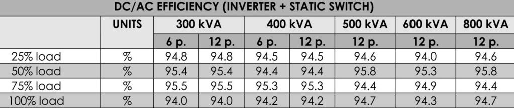
34 5 DC/AC EFFICIENCY (INVERTER + STATIC SWITCH) UNITS 80 kva 120 kva 160 kva 200 kva 6 p. 12 p. 6 p. 12 p. 6 p. 12 p. 6 p. 12 p. 25% load % % load % % load % % load % Table 10: kva UPS Electrical Characteristics (DC/AC Efficiency Inverter + Static Switch) We suggest you to please contact our nearest sales offices/representative in order to get more relevant data related to your plant and application in particular kva UPS technical data, divided for range and type, are shown in the following tables (*) With 400Vac Table 11: kva UPS Electrical Characteristics (Input Rectifier) 34

35 5 Table 12: kva UPS Electrical Characteristics (DC Intermediate Circuit with 400Vac) 35
")
36 5 (*) Also for 0-100% load transient, restore time 20ms ±1% Table 13: kva UPS Electrical Characteristics (Inverter Output) 36

37 5 (*) Load P.F.=0.8 Table 14: kva UPS Electrical Characteristics (Bypass Input Mains) 37

 We suggest you to please")
38 5 Table 15: kva UPS Electrical Characteristics (System Performance) We suggest you to please contact our nearest sales offices/representative in order to get more relevant data related to your plant and application in particular. Table 16: kva UPS Electrical Characteristics (Heat Losses) We suggest you to please contact our nearest sales offices/representative in order to get more relevant data related to your plant and application in particular. Table 17: kva UPS Electrical Characteristics (DC/AC Efficiency Inverter + Static Switch) We suggest you to please contact our nearest sales offices/representative in order to get more relevant data related to your plant and application in particular. 38
39 5 MSS Technical Data kva MSS technical data, divided for range and type, are shown in the following tables: BYPASS INPUT UNIT 250 kva 400 kva 600 kva 800 kva 1200 kva Rated mains Vac voltage Supply - Three phase with neutral Rated Current (*): 380 Vac A Vac Vac Bypass voltage % ±10 tolerance Frequency H 50 or 60 Input frequency % ±2 tolerance Maximum frequency slew rate Hz/sec 0.1 Current rating of neutral cable Protection, bypass line Transient overload (*) Load P.F.=0.8 Table 18: kva MSS Electrical Characteristics (Bypass Input) 2000 kva kva x In 1.15 x In 1 x In - To avoid series fuses, the bypass line should be protected using an external device in the input distribution system. This device should be sized to discriminate with the load protection. ms I/In
40 40

41 6DISPLAY AND CONTROL 6 UPS Display and Control Panel A. UPS Display and Control Panel: Each UPS module of Hipulse is equipped with a 4x20 character alphanumeric display. This automatically provide all information relating to the current status of the UPS as well as being capable of displaying metered values. The display is menu-driven, permitting you to easily navigate through operator screens. B. Metered Values: A microprocessor controls the display functions of the monitoring System. All threephase parameters are displayed simultaneously. All voltage and current parameters are also monitored using true RMS measurements for accurate (± 2%) representation of non-sinusoidal waveforms typical of computers and other sensitive loads. The following parameters are displayed: OUTPUT VOLTAGE (LINE-LINE) INPUT VOLTAGE (LINE) OUTPUT VOLTAGE (LINE-NEUTRAL) TEMPERATURE (BATTERY ROOM) OUTPUT CURRENT (LINE) BATTERY CURRENT OUTPUT REAL POWER (LINE) BATTERY VOLTAGE OUTPUT APPARENT POWER (LINE) BATTERY AUTONOMY % LINE LOAD % BATTERY CHARGE BYPASS FREQUENCY NUMBER OF MODULES IN FAULT (MMU ONLY) INVERTER FREQUENCY BYPASS VOLTAGE (LINE-LINE) C. Power Flow Mimic: Each Hipulse UPS module is equipped with a mimic to indicate power flow to your critical load along with an indication of the availability of the rectifier mains, battery supply and the alternate bypass mains. The mimic provides a quick and easy indication of your load level, including for overload conditions. Under normal operation, the mimic will also display the amount of charge stored in your battery system. During mains failure, the battery charge indication alternates to identify the remaining battery autonomy time; as well as indicating low battery voltage conditions. D. Alarms and Status Information: Alarm and status conditions are reported at the Single Module System (SMS), at the Multi Module Unit (MMU) or at the Main Static Switch (MSS). The display and control panel report the alarms and status information listed in the next table (Table 19). Each alarm is visually displayed in text form and an audible alarm will sound for each alarm displayed. 41
42 6 MESSAGE DESCRIPTION SMS MMU MSS Bypass Switch Open Bypass input isolator (Q2) is open yes X yes X Output Switch Open Output isolator (Q4) is open yes X yes X yes X Rectifier Switch Open Input mains isolator (Q1) is open yes X yes X Battery CB Open Battery circuit breaker is open yes X yes X Manual Bypass Closed Maintenance bypass isolator (Q3) is closed yes X yes X Fan Failure At least a fan is not correctly working yes X yes X yes X Bypass: Absent Bypass mains is failed yes X yes X Bypass: Over Voltage Bypass mains voltage is higher than acceptable range yes X yes X Bypass: Under Voltage Bypass mains voltage is lower than acceptable range yes X yes X Bypass: Frequency Error yes X yes X Bypass mains Frequency is out of an acceptable window Bypass: Phase Rotation Error Bypass power lines have been cross-connected and the phase sequence is incorrect yes X yes X Bypass: SCR Failure One or more of the static switch SCR's has developed a fault yes X yes X Bypass: Off Switching between inverter to bypass is OFF yes X yes X Bypass: Off via Display yes X yes X Switching between inverter to bypass has been selected OFF by means of either the front panel display or an external PC Load on Bypass Bypass mains is powering the load yes X yes X Bypass: Over Temperature Over temperature condition has been detected on the bypass mains yes X yes X Rectifier: Off Rectifier is OFF yes X yes X Rectifier: Off via Display yes X yes X Rectifier: Block Rectifier: Current Limit Rectifier has been selected OFF by means of either the front panel display or an external PC or a switch on UPS µp PCB Rectifier has been blocked by hardware or software failure conditions Rectifier has overtaken settable Input current limit threshold Over temperature condition has been detected on rectifier Rectifier: Over Temperature yes X yes X Rectifier: Fuse Failure Rectifier fuse is blown yes X yes X Inverter: Off Inverter is OFF yes X yes X Inverter: Off Via Display Inverter has been selected OFF by means of either the front panel display or an external PC yes X yes X yes X Inverter: Block Inverter has been blocked by hardware or software failure conditions yes X yes X Inverter: Current Limit Inverter has overtaken settable output current limit threshold yes X yes X Inverter: Over Temperature Over temperature condition has been detected on inverter yes X yes X yes X Inverter: Unsynchronized Inverter is not synchronized with the bypass mains yes X yes X yes X Inverter: Over Voltage Inverter voltage is higher than acceptable range yes X yes X Inverter: Under Voltage Inverter voltage is lower than acceptable range yes X yes X Output: Over Voltage Over voltage condition has been detected on the UPS output yes X yes X yes X Output: Under Voltage Under voltage condition has been detected on the UPS output yes X yes X yes X Output: No Voltage yes X yes X yes X No voltage condition has been detected at the inverter output Table 19: List of alarms and status information available on the display and control panel yes X yes X yes X yes X 42
43 6 Output: Waveform Error Inverter: Frequency Error Inverter: Parallel Error Parallel Bus Open Output voltage peak has flattened caused by an internal inverter problem and therefore the output will be out of limits Frequency error condition has been detected at the inverter output The parallel board has detected a wrong sharing of the load and has blocked its inverter Both of the parallel interconnecting ribbon cables are disconnected (or open circuit) The number of active inverter is below the preset capacity value The system is carrying out a periodic battery test (settable) Battery test is failed; a full check of the battery bank is required yes X yes X yes X yes X yes X yes X yes X yes X (only for 1+N) Nr. Inverters not OK Battery: Under Test yes X yes X Battery: Test Failed yes X yes X Battery: On Load Battery is powering the load yes X yes X Battery discharge has continued beyond a preset Battery: End Of Discharge value yes X yes X Battery: Boost Time Expired Boost time charge elapsed set value yes X yes X DC Bus: Slow Over Voltage DC bus voltage has been overtaking settable threshold for a few time (< 500 Vdc) yes X yes X DC Bus: Under Voltage yes X yes X When the inverter is operating on the battery this message is displayed when the battery voltage has fallen below a preset value Battery: Fuse Failure Battery fuse is blown yes X yes X DC Bus: Fast Over Voltage DC bus voltage has just overtaken pre-defined threshold (> 600 Vdc) yes X yes X Battery: Ground Fault Battery is not longer isolated from ground and there is a danger of electrocution yes X yes X Bypass: Transfer Count The load has been transferred to the bypass more yes X yes X yes X than eight times in one minute. After eight transfers Block the load will remain on bypass Overload Shutdown The load has been transferred to bypass due to an inverter overload yes X yes X Over Temperature Shutdown The load has been transferred to bypass due to an inverter over temperature yes X yes X Emergency Stop Emergency Power Off push-button has been pressed due to operator action yes X yes X yes X Backfeed Fault A failure of the Bypass static devices has resulted in voltage being fed back to the bypass mains yes X yes X Synchro Inhibited The synchronization of the inverter with the bypass line has been inhibited yes X Overload Present It annunciates as soon as the load exceeds 100% of the UPS rating yes X yes X yes X Bad EEPROM Programming It is activated by an internal EEPROM check yes X yes X yes X Error LRC Parameters A LRC (*) Error regarding page 1 parameters (of the yes X yes X yes X Page 1 EEPROM) has been detected Error LRC Parameters A LRC (*) Error regarding page 2 parameters (of the yes X yes X yes X Page 2 EEPROM) has been detected Error LRC Parameters A LRC (*) Error regarding page 3 parameters (of the yes X yes X yes X Page 3 EEPROM) has been detected Error LRC Parameters Alarm History An LRC (*) Error regarding Alarm History parameters has been detected yes X yes X yes X yes X yes X 43
44 6 Error LRC Parameters Event History An LRC (*) Error regarding Event History parameters has been detected X X X Internal Battery Low Internal battery voltage is lower than pre-defined threshold X X X Error LRC Table An LRC (*) Error regarding the Restart Table has been detected X X X Error LRC Panel An LRC (*) Error regarding the EEPROM Panel has been detected X X X Wrong Modem Configuration An LRC (*) Error regarding the Modem configuration has been detected X X X Error LRC Alarm Memory An LRC (*) Error regarding Alarm Memory has been detected X X X No Response from Modem Modem presence test is failed X X X False Modem Command A modem command error has been detected X X X Modem Transmission X X X Modem transmission timeout has been detected Timeout UPS is not responding UPS is not responding X X X Normal operation UPS is normally operating X x x Ecomode Ecomode operation has been selected yes X yes X Autonomy Nr. X UPS not active (*) LRC means Longitudinal Redundancy Check The microprocessor monitors the battery percentage capacity while on charge and the battery time remaining while on discharge It indicates the number of not active module(s) on the System yes yes yes yes yes yes yes yes yes yes yes yes yes yes yes yes yes yes yes yes yes yes yes yes yes yes yes yes yes yes yes yes yes X yes X yes x yes 44

45 7OPTIONAL SOLUTION 7 To further improve the quality of your power quality solution, Hipulse units can be coupled with several optional components. Some of these will enhance your control of the system, some will make the installation easier, while some other will increase the level of protection of your applications. All can significantly add to a Hipulse system and suit your needs of a complete Power Quality Solution. The benefits and applications of each will be clarified in the following paragraphs, however, you can confidently refer to any Liebert or Liebert Hiross representative should you need further explanation about each of the following solutions. Optional components fall broadly under three categories: communications solutions power reliability solutions additional components Below is a brief description of all of them. COMMUNICATIONS SOLUTIONS Monitoring And Shutdown Software HiLink UPS Monitor HiLink UPS Monitor is a cost effective supervision software that will monitor all status, alarm and metered information at the Hipulse UPS. The information is displayed on the computer monitor as a live copy of the UPS display mimic, or can be made available as a data log file. Log files can be further exported in common spreadsheet and database formats for charting and trending. HiLink UPS Monitor allows monitoring not only of single UPS units, but of a whole system. A system can be composed up to 6 UPS units and 1 optional MSS. Only one connection with the server is needed in this case. The software can be further coupled with a Remote Control Panel (see below) for extra flexibility. For remote monitoring one modem connected to a telephone line is required per system this means that each installation, composed of up to 6 units plus MSS will share one modem and one telephone line only, therefore saving connection and setup costs. On a TCP/IP or dial-up network, information can be displayed also on remote computers, and status messages and alarms can be sent via or to out-of-band devices such as pagers or SMS compatible mobile phones. HiLink UPS Monitor runs on Microsoft Windows 95/98/NT4/2000 platforms. When used in combination with MultiLink 3 the software will allow cross platform shutdown of servers and workstations. Customer Values Complete UPS status information. Better management of your critical applications and equipment. Improved monitoring and enhanced availability. 45


46 7 MultiLink MultiLink 3 offers the best protection for your computer and network environment by providing a flexible multi-platform network shutdown solution. MultiLink sits on your workstation or server, monitoring basic UPS status, and ensures a graceful unattended shutdown in the event of an extended power failure. For 7200 and Hipulse UPS or MSS units communications can be obtained using an OpenComms NIC (SNMP/HTTP interface) or by using HiLink UPS Monitor as a bridge. MultiLink supports MS Windows, Linux, HP-UX, Novell Netware, Sun Solaris and IBM AIX platforms. Customer Values Flexible network and multiple platform shutdown. SiteScan SiteScan Centralized Monitoring systems are a combination of interface/control modules and a front end software package. When teamed with a host computer, the SiteScan systems enable communications from Liebert environmental and power units - as well as many other pieces of analog or digital equipment - and provide monitoring, control and alarm management. SiteScan is a monitoring solution for critical environments that utilizes a facility-view approach: its monitoring features give you decision-making power to effectively manage the equipment that is critical to your business. Designed with flexibility for large, complex systems as well as smaller single-site facilities, the Liebert SiteScan line of products can provide real-time status and alarms. Additionally, reporting is available with user-friendly enhanced graphics screens, or in basic text format. Interface Options Hirolink IGM (Hirovisor 2000 Interface) Hirolink IGM is an interface device that allows integration of your Liebert Hiross UPS equipment for monitoring via the Hirovisor2000 supervision software. Customers requiring integration with a Hirovisor2000 monitoring system will need to have one Hirolink IGM fitted on each UPS. Hirovisor is a sophisticated monitoring solution that allows you to monitor all Liebert Hiross Power UPS and HPAC (High Precision Air Conditioning) equipment from one integrated platform. Features include a sophisticated SMS messaging platform, advanced logging facilities and additional useful remote monitoring tools. Hirovisor2000 is the ideal solution when you need 24 by 7 availability, and readily available information, even in distant locations, regardless of type of equipment. As such Hirovisor 2000 is the platform of choice for our Liebert Hiross Services group, which provides 24x7 monitoring and assistance for all Liebert and Liebert Hiross equipment across Europe. 46
47 7 Customer Values Integration and control monitoring together with all Liebert Hiross HPAC and UPS equipment. Enhanced Availability and Reduced Cost of Maintenance. OpenComms NIC (SNMP/HTTP Interface) The OpenComms Network Interface Card provides status monitoring and alarm information through SNMPv1 protocol messages. This option allows connection over a 10-baseT Ethernet network. Additionally, it will also transmit the same status information and all measured parameters for display to a web browser via the HTTP protocol. The information is visible on common browsers like Internet Explorer 4.0 or better, Netscape Navigator 4.0 or better, and Opera 5.0 or better. Customer Values Popular Internet standard protocol. Web enabled monitoring. NMS integration, ideal in networking environments and Information Technology companies. Modbus/Jbus Option (BMS Interface) The Modbus/Jbus Option can be installed on Hipulse units by replacing a programmable component on the UPS Logic Board. This option allows communication between UPS (or MSS) and any Building Management System, by using the standard Modbus/Jbus RTU protocol. Building Management Systems are sophisticated programs that help facility managers and technicians monitor and control temperature and ventilation conditions, security and fire safety, power distribution systems as well as power supply systems - like UPS units - in non-residential buildings. Customer Values Works with most common Building Management System. Simple and time-tested solution. 47


48 7 Example of Modbus/Jbus system architecture Other Hardware Optional Equipment Remote Control Panel This option allows the system alarms and variables to be displayed remotely from the Hipulse UPS. It can be connected up to six UPS via RS-485 serial interface. An audible warning accompanies the above alarm conditions and it can be cancelled by pressing the reset push-button, while the alarm indication will remain illuminated until the condition is rectified. This type of Man Machine Interface can be divided in three functional areas: LCD Display, equipped with a 4x20 character alphanumeric display, which automatically provides information relating to your System and metered values current status. The display is menu driven, permitting you to easily navigate through operator screens. System alarm LED, (left side) representing the main information about your System status. System apparatus LED, (right side) representing the main information about your connected Apparatus status. Customer Values Facilitates Management Information System (MIS) for You to keep vigil and monitor UPS status to ensure enhanced availability for your critical loads LED SIGNALLING: 1-6 UPS 7 MSS (ISR) 8 BYPASS 9 BATTERY 10 UPS 11 ALARM 48 Remote Control Panel
49 7 Relay Boards (standard relay contact boards) I/O Alarm Interface Board (iseries-as/400 Interface): this board allows connections for two input signals on a terminal block. One remote input allows the inverter s shutdown, the second one can be set up to reduce the input current limit, to inhibit the battery charge or to synchronize the inverter. The board provides 9 critical UPS alarms (4 of these are provided as a standard interface to an IBM iseries/as400 computer), via volt-free relay contacts (max 1 A, 50 Vdc). I/O Extension Board: this board further increases the number of signals that can be used to monitor the UPS, via volt-free relay contact (max 1 A, 50 Vdc) by transmitting 6 additional events. I/O iseries-as/400 Expansion Board: this board provides an additional interface for connection with 3 IBM iseries-as/400 systems. 4 critical signals are provided via volt-free relay contacts (max 1 A, 50 Vdc). Remote Alarm monitor: the Remote Alarm Monitor (RAM) Board can be used in conjunction with one of the I/O Alarm Interface boards (described above) to display UPS alarms at a remote station up to 100 meters away from the main equipment. Critical events are accompanied by flashing LEDs and audible sounds. Sound alarms can be turned off by pressing the reset push-button, while the LED indicators will remain lit until the UPS returns in normal operation status. Relay Boards offer different types of messages depending whether they are fitted on a Hipulse UPS or MSS unit. Below is a list of the relevant messages communicated by the boards: Board Type Messages UPS I/O Interface Board UPS Bypass(*) Battery Low(*) UPS ON(*) Utility Failure(*) Bypass Failure Low Battery Load on Mains Load on Bypass Load on Inverter UPS Extension Board Battery on Load Overload Inverter OverTemp Invert Outof Sync Transfer on Bypass Inhibited Rectifier/Mains Failure Bypass Failure (*) These messages are used for communicating to IBM iseries-as/400 servers. MSS I/O Interface Board N.Invertersnot OK Load on Mains Load on Inverter MSS Extension Board Number of UPS not Active MSS Overload MSS OverTemp Inverters Out of Sync Manual Bypass Closed BackFeed Fault 49
50 7 POWER RELIABILITY SOLUTIONS HiSync Dual Bus Synchroniser (DBS) HiSync DBS allows the parallel use of 2 different systems of UPS, each consisting of 1 up to 6 machines. The two systems will be following the same frequency even if connected to two different lines or using the battery power. Hisync (DBS) has been designed to ensures that. In fact, it is able to synchronize the slave power bus to the master one (selectable), checking, at the same time, also the synchronism of each UPS. If a difference between the two power bus is detected, HySinc (DBS) will pilot UPS feeding the slave bus in order to keep both bus frequency within an acceptable value. Customer Values This special feature is necessary to perform a dual bus system, which is one of the most reliable system for your critical loads. Enhanced Reliability for You. Sour Source#1 Source#2 Normal Mains UPS1 Normal UPS6 Mains Normal Mains UPS1 UPS6 Normal Mains HiSync (DBS) HiSwitch 1 HiSwitch 2 Diagram 10 - HiSync Dual Bus Synchroniser (DBS) Critical Load 1 Critical Load 2 50
51 7 HiSwitch This automatic static transfer switch provides independent source transfers to meet the highest level of power availability and fault tolerance. Thanks to HiSwitch, a dual bus distribution system is made available to all downstream loads. By continuously monitoring the power quality of two power sources, HiSwitch provides protection against power failure by transferring to the alternative power source (selectable) in near instantaneous changeovers. The alternative power source must be kept in synchronism, to avoid the danger of out of phase transfers, which could result in load loss. HiSwitch avoids common points of source failure making it the ideal solution to maintenance problems that are both unexpected and unwanted. HiSwitch advanced communication features enable you to monitor network power and to prevent your system from serious damages caused by blackout or other problems. A wide range of HiSwitch sizes are available, from 100 up to 1200 A. Customer Values This special feature allows you to obtain a true power redundancy, eliminating single points of failure. Enhanced availability and reliability for your critical loads. Investment Protection for You. Source#1 Source#2 Q4 Q1 Q2 Q5 Power Supply Diagram 11 - HiSwitch HiswitchSW1 Logic Driver Q3 OUTPUT HiswitchSW2 Hiswitch 51
52 7 Input Filter Properly designed tuned filters are available to reduce the most critical harmonic pollution (5th and 11th). They also can improve the Hipulse input power factor, leading Power Factor (P.F.) from 0,8 up to 0,93. These input filters can be installed without any additional system footprint and their performances are shown in tables 4 & 11. Input Isolation Transformer Input Isolation Transformers are required in case of having a galvanic isolation between Input/Bypass Mains and UPS Output. They are normally a Delta/ZigZag double wound transformer and they are available for every range of UPS ( kva). They are housed in an optional cabinet in which the nonautomatic circuit breaker with fuses are also installed. Input isolation transformer are designed to power both rectifier and bypass mains, depending on their size. Transient Voltage Surge Suppressor - TVSS This option is an advanced Transient Voltage Surge Suppressor. It has been designed for medium and heavy duty applications with capacities from 100 up to 400 ka per phase. TVSS is normally connected at the bypass path of Hipulse or inside the HiSwitch as an optional item. Customer Values Input Filter Lower cost of ownership, due to lower electricity bill and reduced up-stream power pollution. Input Isolation Transformer Enhanced optional protection: Galvanic Isolation Reduced Fault Current Reduce the harmonic currents back on mains when the UPS is on bypass Protection (optional) against Battery Ground Fault Creation of Neutral Top Cable Entry It is possible to have a top cable entry option when the power supply cables are coming from the top of UPS. This kit incorporates a bus bar cabling system and flexible cables to connect to the Hipulse input/output terminals. This option is available for a wide range of Hipulse UPS ratings. Battery Circuit Breaker (BCB) Each Hipulse UPS module has the optional properly rated circuit breaker (500 Vdc) to isolate it from your battery. This breaker is to be housed in a separate enclosure, or mounted inside an optional battery cabinet. When the BCB is open, there will be no battery voltage inside the Hipulse enclosure. Each Hipulse module will automatically be disconnected from your battery by opening its breaker when it reaches the minimum discharge voltage level or when signaled by other control functions. 1+N Parallel Interface Kit This kit allows UPS modules to operate in parallel mode, with SMS (Single Module System) without the use of MSS (Main Static Switch). Battery Ground Fault Sensor This option allows to detect a battery ground fault; it gives an alarm contact output that can be managed by your system. 52
53 7 Battery Temperature Sensor This option allows the temperature compensated charging, in order to optimize on your battery lifetime. Battery Control Board This option allows to control the Battery Circuit Breaker by piloting its trip coil. Customer Values Top Cable Entry This TCE may be used for both top and bottom cable entry, ease of installation, user flexibility Battery Circuit Breaker This feature offers extra protection to the battery, disconnecting it whenever conditions may require so. By avoiding that the battery works under inappropriate conditions, you will increase the battery life and your equipment s safety.the safety tools employed on Hipulse UPS are designed with no compromises regarding safety and functionality. Investment protection for you, additional safety for your maintenance personnel. Battery Control Board The battery control board is required when the BCB is fitted in the battery cabinets supplied by others. Protection Degree (IP) This standard describes a system for classifying the degrees of protection provided by the enclosures of the electrical equipment. Standard Hipulse enclosure is IP20, but it is possible to reach up to IP4x enclosure for most of the kva ratings of Hipulse. Customer Values This feature allows Hipulse to operate in heavier environmental conditions. Enhanced availability. 53
54 54

55 8MAINTENANCE AND SERVICE 8 Maintenance and Service can be activated and built around customer needs. This could include services listed in the following: Routine Maintenance, which includes Equipment refurbishing and re-commissioning Battery maintenance, that typically includes regular inspection and maintenance visits On site visits in order to assure preventative maintenance program Remote diagnostic Service 24-hour emergency call-out Performance Contracting, a total site service where Company will take responsibility for everything from routine maintenance to re-commissioning for support equipment, across a site or group of sites. Example of Remote diagnostic service organization 55
56 56

57 9UPS DELIVERY SUBMITTALS 9 Hipulse is generally supplied with one (1) user manual to include details for: A. Functional description for the equipment with block diagrams. B. Detailed installation drawings, including all terminal locations for power and control connections for both the UPS and battery system. C. Safety precautions. D. Step-by-step operating procedures. E. General maintenance guidelines. Hipulse is supplied with a record of pre-shipment final factory test report. 57
58 58
59 10 QUALITY ASSURANCE 10 Manufacturer Qualifications Hipulse is a product of a minimum of twenty years of reach experience and wealth of knowledge in the design, manufacture and testing of solid-state UPS system. Liebert Hiross is certified to ISO Factory Testing Before shipment, Hipulse is fully tested internally to ensure compliance with the specification. 11 WARRANTY 11 UPS Warranty We warrant the unit against defects in workmanship for 12 months after initial start-up or 15 months after ship date, whichever comes first. Battery Warranty The battery manufacturer s standard warranty will generally be passed through to the end user. 59
60 60

61 12 VALUES DECLARATION NOTES 12 When anyone is requested to provide any kind of parameter, he will find out that there are many ways to proceed and statistical interpretation. How does this process and the value distribution work? The desired values are spread between a minimum and a maximum (see graph 1 as an example of efficiency measurement) but are mainly concentrated near a mean value which will be the most common one. The standard deviation (shown in graph 1) is a value that is mathematically calculated in order to give information about the event's distribution percentage and strictly linked with the shape of the Gauss-bell. A rigorous declaration of a value should consist of the mean value and the standard deviation value, in order to allow the customer to draw the Gauss-bell curve and have a clear view of the situation. Graph 1 What does Liebert Hiross do? We are actually very conservative regarding the affirmation of the performances of our UPS and the values we declare are realistic as being the minimum ones (see left-hand side arrow in the curve) at the left of the standard deviation value. This allows us to state: the efficiency will be not less than..% without any tolerance. Why have we chosen such a solution? Because for the customer it s extremely difficult to assess if the claimed value is really true or the result of a generous tolerance. He should, in fact, test hundreds of machines to realize that standard deviation value or the mean one is not correct. The only way to ensure the quality and the performances of a machine is actually to assure a minimum value, that the customer will be able to consider good enough, according to his needs. Come to visit us and attend a witness test, we will be glad to show you our factory and products! 61
R E C T I F I E R I N V E R T E R C O N V E R T E R MP7
 Uninterruptible Power Supply Product Specifications Description The industrial UPS provides your critical equipment with uninterruptible 3 phase AC power. Using high frequency dual conversion technology,
MP7. Uninterruptible Power Supply
 Uninterruptible Power Supply PRODUCT SPECIFICATIONS Description The industrial UPS provides your critical equipment with uninterruptible 3 phase AC power. Using high frequency dual conversion technology,
Tel: AC Power for Business-Critical Continuity TM
 Tel: +852-2690-4118 AC Power for Business-Critical Continuity TM Anticipating Technology Changes Through Adaptive Architecture Today, you need a power infrastructure that can work across your enterprise
Liebert NX - Next Generation UPS for protecting your Business Critical Systems. AC Power Systems for Business-Critical Continuity
 - Next Generation UPS for protecting your Business Critical Systems AC Power Systems for Business-Critical Continuity Advanced UPS Technology Protects Modern IT Equipment Today s advanced digital computing,
Hipulse-U UPS 80kVA - 500kVA Utmost Reliable Power Solution for Critical Business Applications
 TM Hipulse-U UPS 80kVA - 500kVA Utmost Reliable Power Solution for Critical Business Applications WE ARE VERTIV Vertiv, formerly Emerson Network Power, designs, builds and services mission critical technologies
(1986; Rev. 1989) Molded Case Circuit Breakers and Molded Case Switches. (1985; Rev. 1988) Enclosures for Electrical Equipment (1000 Volts Maximum)
 Molded Case Circuit Breakers and Molded Case Switches. (1985; Rev. 1988) Enclosures for Electrical Equipment (1000 Volts Maximum)") Section 16306 50/60-HERTZ (HZ) SOLID STATE FREQUENCY CONVERTER Index PART 1 GENERAL PART 2 PRODUCTS 1.1 References 2.1 Frequency Converters 1.2 Factory Tests 2.2 Conduit and Fittings 1.3 Submittals 2.3
Section 16306 50/60-HERTZ (HZ) SOLID STATE FREQUENCY CONVERTER Index PART 1 GENERAL PART 2 PRODUCTS 1.1 References 2.1 Frequency Converters 1.2 Factory Tests 2.2 Conduit and Fittings 1.3 Submittals 2.3
UPS. centric Hot scalable modular 3-phase UPS Delivers 25 up to 200 kva/kw INFINITE POWER. Mission Critical Applications
 INFINITE POWER Mission Critical Applications UPS UNINTERRUPTIBLE POWER SUPPLY centric Hot scalable modular 3-phase UPS Delivers 25 up to 200 kva/kw Rack-mountable modules designed for blades, data-center,
RT12-240V/2.4kW Rectifier Specification
 The RT12-240V/2.4kW is a switched mode rectifier (SMR) module that delivers up to 2.4kW of output power (and up to 11A output current) into a 240V nominal DC system. The RT12 suits AC supply voltages between
PHASE ONE Series 700: Uninterruptible Power Supply (UPS) Systems
 Systems") PHASE ONE Series 700: Uninterruptible Power Supply (UPS) Systems Features General Universal Application Data Processing Telecommunications Medical/Health Care Manufacturing/ Process Control Quality Design
PHASE ONE Series 700: Uninterruptible Power Supply (UPS) Systems Features General Universal Application Data Processing Telecommunications Medical/Health Care Manufacturing/ Process Control Quality Design
RT4F-120V/20A-WAC RECTIFIER
 The RT4F-120V/20A-WAC is a switched mode rectifier/charger module designed to provide up to 20A of output current into a 120V nominal system. This charger has been designed for use in conjunction with
Liebert NXr Series 30kVA to 160kVA. AC Power for Business-Critical Continuity TM
 Liebert NXr Series 30kVA to 160kVA AC Power for Business-Critical Continuity TM Anticipating Technology Changes Through Adaptive Architecture Today, you need a power infrastructure that can work across
RT4F-110V/25A RECTIFIER
 The RT4F-110V/25A is a hot-pluggable switched mode rectifier (SMR) module designed to provide up to 25A of output current into a 110V nominal system. Examples of such systems are 60 cells lead acid (136V
10 kva 3/1 15 kva 3/1 20 kva 3/1 10 kva 3/3 15 kva 3/3 20 kva 3/3 30 kva 3/3 40 kva 3/3 UOUS SERV WARRANTY
 OF CONTINUOUS SERVICE YEARS WARRANTY B8000 FXS 10-40kVA BORRI B8000 FXS With disturbances to the electrical supply being one of the major causes of IT downtime, the UPS system is regarded as the most critical
SmartOnline SVX Series 120kVA Modular, Scalable 3-Phase, On-line Double-Conversion 400/230V 50/60Hz UPS System
 SmartOnline SVX Series 120kVA Modular, Scalable 3-Phase, On-line Double-Conversion 400/230V 50/60Hz UPS System MODEL NUMBER: SVX120KL Highlights 120kVA / 120kW modular, scalable, 3-phase, Large-Frame tower
the Centric 300 An advanced modular UPS up to 1800kVA/kW
 the Centric 300 An advanced modular UPS up to 1800kVA/kW 1 Gamatronic, Israel s Leading Power Electronics Company True to the exceptional reputation earned by Israeli technology companies, Gamatronic has
RT4F-48V/50A-WAC RECTIFIER
 The RT4F-48V/50A-WAC is a switched mode rectifier (SMR) module designed to provide up to 58A of output current into a 48V nominal system, over a wide range of AC input voltage. This rectifier has been
RT4B-110V/12A RECTIFIER
 The RT4B-110V/12A is a switched mode rectifier (SMR) module designed to provide up to 12A of output current into a 110V nominal system. It can be used with or without a cooling fan. With a fan it runs
Technical Data Sheets Uninterruptible Power Supply LP11 Series UPS kva
 GE Critical Power Technical Data Sheets Uninterruptible Power Supply LP11 Series UPS 3 5 6 8 10 kva GE Consumer & Industrial SA General Electric Company CH 6595 Riazzino (Locarno) Switzerland T +41 (0)91
PRODUCT. Battery Charger
 PRODUCT Battery Charger Model : BC 9080 Battery Charger The ICD Battery Charger is designed to supply required DC Voltage and Current to the connected load and recharge the Battery on boost charging over
Product Specifications
 Product Specifications Models: USC-10001, USC-10002 USC-20001, USC-20002 USC-30001, USC-30002 Guide Specification for UniStar C Series Rack/Universal 1, 2, 3Kva Single-Phase, On-Line Double Conversoin
Liebert NX Series. 30kVA to 200kVA. AC Power for Business-Critical Continuity TM
 Liebert NX Series 30kVA to 200kVA AC Power for Business-Critical Continuity TM Anticipating Technology Changes Through Adaptive Architecture Today, you need a power infrastructure that can work across
LEVELUPS T3. SERIES kva ONLINE UPS 3:3 PHASE VFI TYPE. Highest Reliability and Robust Protection for Industrial Loads
 LEVELUPS T SERIES DATA CENTER MEDICAL TRANSPORT INDUSTRY EMERGENCY VFI TYPE PF= 0.9 Service UPS ONLINE TOWER POWER FACTOR SERVICE HIGHLIGHTS Built In Inverter Transformer for DC-AC Galvanic Protection
SmartOnline SVX Series 90kVA 400/230V 50/60Hz Modular Scalable 3-Phase On-Line Double- Conversion Medium-Frame UPS System, 5 Battery Modules
 SmartOnline SVX Series 90kVA 400/230V 50/60Hz Modular Scalable 3-Phase On-Line Double- Conversion Medium-Frame UPS System, 5 Battery Modules MODEL NUMBER: SVX90KM3P5B Highlights 90kVA/90kW Modular, Scalable,
ATS-16 HV USER MANUAL. Automatic Transfer Switch 16A / 230Vac V090318
 ATS-16 HV Automatic Transfer Switch 16A / 230Vac USER MANUAL V090318 SAFETY Intended use The ATS-16 HV device serves as a power source selector to provide improved power supply for connected loads. ATS-16
1PH RACK 19 SINGLE PHASE UPS Rev. 11 SR 6kVA 10kVA
 The SR series on line double conversion UPS with full time Digital Signal Processor control technology is the perfect solution for mission critical users who demand high reliability, availability and performance
Galaxy VX. From 500 to 1500 kw N+1 Parallel solutions up to 4000 kw 380V / 400V / 415V / 440V. schneider-electric.com/ups
 Galaxy VX Highly efficient, scalable, three-phase power protection with flexible operating modes and ECOnversion for large facilities, data centers, and business-critical applications. From 500 to 1500
POWERVAR SECURITY PLUS SERIES DETAILED UPS SPECIFICATION (8kVA 10kVA)
") POWERVAR SECURITY PLUS SERIES DETAILED UPS SPECIFICATION (8kVA 10kVA) A55-00017 SEC PLUS 8-10 KVA MAREKTING SPECS REV. A 9/10 8kVA, 10kVA POWERVAR Isolated On-Line UPS Specifications Index 1.0 General
POWERVAR SECURITY PLUS SERIES DETAILED UPS SPECIFICATION (8kVA 10kVA) A55-00017 SEC PLUS 8-10 KVA MAREKTING SPECS REV. A 9/10 8kVA, 10kVA POWERVAR Isolated On-Line UPS Specifications Index 1.0 General
PLT. Breaker-based transfer switch open, closed or soft transition amps. Specification sheet
 Specification sheet PLT Breaker-based transfer switch open, closed or soft transition 800 3000 amps Description PLT breaker-based transfer switches are designed for operation and switching of electrical
MUST900 Modular UPS. Datacenter & servers. Internet centers. Local Area Networks (LAN) Telecommunication devices. Emergency application
 Telecommunication devices. Emergency application") MUST900 Modular UPS 30-300 kva modular UPS - up to 900 Datacenter & servers Internet centers Local Area Networks (LAN) Telecommunication devices Emergency application Smart Energy Solutions HOT SWAP 0.9
MUST900 Modular UPS 30-300 kva modular UPS - up to 900 Datacenter & servers Internet centers Local Area Networks (LAN) Telecommunication devices Emergency application Smart Energy Solutions HOT SWAP 0.9
APMTM UPS 18kW - 90kW The Flexpower Technology for mission critical applications
 APM UPS 18kW - 90kW The Flexpower Technology for mission critical applications WE ARE VERTIV Vertiv, formerly Emerson Network Power, designs, builds, and services mission critical technologies that enable
Keor HPE UPS THREE-PHASE UPS. from 60 to 200 kw GLOBAL SPECIALIST IN ELECTRICAL AND DIGITAL BUILDING INFRASTRUCTURES
 Keor HPE UPS THREE-PHASE UPS from 60 to 200 kw GLOBAL SPECIALIST IN ELECTRICAL AND DIGITAL BUILDING INFRASTRUCTURES LEGRAND UPS SERVICE continuity ENERGY efficiency SUPERIOR PERFORMANCES Legrand, world
RT7-48V/6kW Specification
 The RT7-48V/6kW is a 3 phase, active power factor corrected, switched mode rectifier (SMR) module designed to provide up to 6kW of output power (100A nominal) into a 48V nominal system. This rectifier
Modes of Operation The UPS shall be designed to operate as a true on-line system in the following modes:
 5K Modular UPS Guide Specifications for a 4 to 16 KVA (208/120V or 240/120V) Single - Phase System 1.0 General 1.1 Summary This specification describes the 5K Modular UPS, a modular uninterruptible power
The quality management system is. Mitsubishi Electric Corporation Kobe Works has been approved to ISO9001:2000.
 7011A_JAN_2011_REVISED_88776_A_7011A 2/1/11 12:57 PM Page 1 7011A Series (6kVA to ) Advantages UNINTERRUPTIBLE POWER SUPPLIES Advanced IGBT technology in both the rectifier and inverter True double conversion
SmartOnline SV Series 20kVA Small-Frame Modular Scalable 3-Phase On-Line Double- Conversion 208/120V 50/60 Hz UPS System, No SVBM Battery Module
 SmartOnline SV Series 20kVA Small-Frame Modular Scalable 3-Phase On-Line Double- Conversion 208/120V 50/60 Hz UPS System, No SVBM Battery Module MODEL NUMBER: SV20KS1P0B Highlights Scalable capacity up
MGE Galaxy /50/60/80/100/130 kva. The recommended power protection for all critical applications
 MGE Galaxy 5000 40/50/60/80/100/130 kva The recommended power protection for all critical applications 40 130 kva state-of-the-art three-phase power protection designed to meet a wide range of requirements
LEVELUPS T3 3 UPS. SERIES kva ONLINE UPS 3:3 PHASE VFI TYPE. Highest Reliability with Embedded Isolation Transformer
 LEVELUPS T SERIES DATA CENTER MEDICAL TRANSPORT INDUSTRY EMERGENCY Three LEVEL UPS VFI TYPE PF=.0 Service UPS ONLINE TOWER POWER FACTOR SERVICE HIGHLIGHTS True Three Level Rectifier and Inverter Technology
Keor HPE UPS. THREE-PHASE UPS from 60 to 300 kw GLOBAL SPECIALIST IN ELECTRICAL AND DIGITAL BUILDING INFRASTRUCTURES
 Keor HPE UPS THREE-PHASE UPS from 60 to 300 kw GLOBAL SPECIALIST IN ELECTRICAL AND DIGITAL BUILDING INFRASTRUCTURES LEGRAND UPS SERVICE continuity ENERGY efficiency SUPERIOR PERFORMANCES Legrand, world
SmartOnline SV Series 40kVA Medium-Frame Modular Scalable 3-Phase On-Line Double- Conversion 208/120V 50/60 Hz UPS System, 2 Battery Modules
 SmartOnline SV Series 40kVA Medium-Frame Modular Scalable 3-Phase On-Line Double- Conversion 208/120V 50/60 Hz UPS System, 2 Battery Modules MODEL NUMBER: SV40KM2P2B Highlights Scalable capacity up to
ALL PSU Ltd ROTATION+ 6kVA - 10kVA PARALLEL ON LINE DOUBLE CONVERSION
 ALL PSU Ltd Unit D6 Laser Quay, Culpeper Close Medway City Estate, Rochester, Kent, ME2 4HU Phone: 01634-725527 Fax: 01634-739111 E-mail: sales@allpsu.co.uk Web: www.allpsu.co.uk ROTATION+ 6kVA - 10kVA
SMARTONLINE E3 UPS SYSTEMS
 SMARTONLINE E3 UPS SYSTEMS Extremely efficient protection for your most important equipment IDEAL OUTPUT POWER PROTECTS CRITICAL SYSTEMS On-line, double conversion operation continuously delivers precision-regulated,
Liebert EXM UPS 1.0 GENERAL. Single-Module Uninterruptible Power System kVA, 480V GUIDE SPECIFICATIONS 1.1 SUMMARY 1.
 1.1 SUMMARY Liebert EXM UPS Single-Module Uninterruptible Power System 50-250kVA, 480V GUIDE SPECIFICATIONS 1.0 GENERAL These specifications describe requirements for an Uninterruptible Power System (UPS)
THOR Modular. Modular UPS system. Online double-conversion Scalable Decentralized Parallel. Modular. 10, 20, 30, 40kVA modules kVA systems
 Power Supplies Modular THOR Modular Modular UPS system Online double-conversion Scalable Decentralized Parallel Modular 10, 20, 30, 40kVA modules 10-520kVA systems Power factor 1.0 at 10/20kVA/kW modules
MGE Galaxy /30/40/60/80/100/120 kva. The recommended power protection for all critical applications.
 MGE Galaxy 5000 20/30/40/60/80/100/120 kva The recommended power protection for all critical applications. 20 120 kva state-of-the-art, threephase power protection designed to meet a wide range of requirements
9900B UPS. The POWER of Green UNINTERRUPTIBLE POWER SUPPLIES
 UNINTERRUPTIBLE POWER SUPPLIES 9900B 9900B UPS UNINTERRUPTIBLE POWER SUPPLIES 300 kva / 300KW 500 kva / 500KW 750 kva / 750KW The POWER of Green EXCEPTIONAL EFFICIENCY The NEW 9900B Series UPS will deliver
Distributed by. Keor T UPS THREE-PHASE UPS. from 10 to 120 kva GLOBAL SPECIALIST IN ELECTRICAL AND DIGITAL BUILDING INFRASTRUCTURES
 Distributed by Keor T UPS THREE-PHASE UPS from 10 to 120 kva GLOBAL SPECIALIST IN ELECTRICAL AND DIGITAL BUILDING INFRASTRUCTURES T THREE-PHASE UPS T has been designed with advanced technologies and the
SagFighter Active Voltage Conditioner / Sag Ride Through (SRT)
") Utility Systems Technologies, Inc. P.O. Box 110 Latham, NY 12110 SagFighter Active Voltage Conditioner / Sag Ride Through (SRT) Overview The SagFighter is an industrial-grade, solid state, electronic voltage
Utility Systems Technologies, Inc. P.O. Box 110 Latham, NY 12110 SagFighter Active Voltage Conditioner / Sag Ride Through (SRT) Overview The SagFighter is an industrial-grade, solid state, electronic voltage
RT9-48V/1.4kW Rectifier Specification
 The RT9-48V/1.4kW is a switched mode rectifier (SMR) module that delivers up to 1.4kW of output power (and up to 30A output current) into a 48V nominal DC system. The RT9 suits AC supply voltages between
MODULYS GP Unique, fully modular and redundant solution Green Power 2.0 range from 25 to 600 kva/kw
 Unique, fully modular and redundant solution The solution for > Computer rooms > Data centres > Banks > Healthcare facilities > Insurance > Telecom Advantages > Ensures absolute business continuity > Aligns
SmartOnline SVTX Series 3-Phase 380/400/415V 30kVA 27kW On-Line Double-Conversion UPS, Tower, Extended Run, SNMP Option
 SmartOnline SVTX Series 3-Phase 380/400/415V 30kVA 27kW On-Line Double-Conversion UPS, Tower, Extended Run, SNMP Option MODEL NUMBER: SVT30KX Highlights On-line double-conversion topology, VFI operation
GAMATRONIC, A SolarEdge Division.
 GAMATRONIC, A SolarEdge Division. 17 Hartum Street, POB 45029, Jerusalem 9777517,Israel Tel: +972-2-5888222 Fax: +972-2-5828875 e-mail: info@gamatronic.com www.gamatronic.com The Power+ Premium 60 is
MODULYS GP Unique, fully modular and redundant solution Green Power 2.0 range from 25 to 600 kva/kw
 Unique, fully modular and redundant solution The solution for > Computer rooms > Data centres > Banks > Healthcare facilities > Insurance > Telecom Advantages > Ensures absolute business continuity > Aligns
Modular UPS S KVA
 Scalable 3 - phase, double conversion UPS system with hot-plug design up to 220 KVA (n + 1). The modular design with 20 KVA modules makes any system up or downgrade flexible and avoids high inv estment
APC Matrix-UPS 3kVA 208V/240V In 120/208/240V Out
 APC Matrix-UPS 3kVA 208V/240V In 120/208/240V Out APC Matrix-UPS, 2250 Watts / 3000 VA,Input 208V / Output 120V, 208V, Interface Port DB-9 RS-232, SmartSlot, Extended runtime model Includes: CD with software,
E-Series Site Preparation Guide
 E-Series Site Preparation Guide September 2017 215-11797_A0 doccomments@netapp.com Table of Contents 3 Contents Deciding whether to use this guide... 10 Specifications of the model 3040 40U cabinet...
CUS150M1 Instruction Manual
 BEFORE USING THE POWER SUPPLY UNIT Be sure to read this instruction manual thoroughly before using this product. Pay attention to all cautions and warnings before using this product. Incorrect usage could
9900AUPS. Efficiency UNINTERRUPTIBLE POWER SUPPLIES 80KVA 225KVA
 UNINTERRUPTIBLE POWER SUPPLIES 9900A 9900AUPS UNINTERRUPTIBLE POWER SUPPLIES 80KVA 225KVA Efficiency & F L E X I B I L I T Y EXCEPTIONAL EFFICIENCY The 9900A Series UPS delivers as much as 96.3% system
3 Uninterruptible Power Systems
 S5K Modular Series Uninterruptible Power Systems (UPS) This easily upgraded and flexible UPS provides the protection you want, when you need it. The 5K Modular is scalable from 4 to 20 kva, offering many
APC Symmetra LX. GUIDE SPECIFICATIONS FOR 4kVA-16kVA Uninterruptible Power System
 APC Symmetra LX GUIDE SPECIFICATIONS FOR 4kVA-16kVA Uninterruptible Power System PART 1 - GENERAL 1.1 SUMMARY A. This specification describes the operation and functionality of a continuous duty, singlephase,
DPA UPSCALE TM RI kw Technical Specifications
 DPA UPSCALE TM RI 10-80 kw Technical Specifications Edition 18.06.2012 Copyright 2015 ABB, All rights reserved. TABLE OF CONTENTS 10.1 DPA UPScale RI SYSTEM DESCRIPTION... 3 10.2 TECHNICAL CHARACTERISTICS
UPS Sentry MPS. SENTRY MPS is also compatible with different battery technologies: openvase lead acid and AGM and Gel VRLA, NiCd.
 Quality Power Supply SENTRY MPS is an on-line double conversion (VFI SS 111 in accordance with IEC EN 620406-3) with a transformer isolated inverter. With a compact footprint and high power quality output,
Symmetra PX. Symmetra PX 48kW Scalable from 16kW to 48kW. Modular, Scalable, High-Efficiency Power Protection for Data Centers
 Modular, Scalable, High-Efficiency Power Protection for Data Centers Symmetra PX 48kW Scalable from 16kW to 48kW > High Performance, Right-Sized 3-Phase Power Protection with Industry-Leading Efficiency,
QUINT-PS/ 1AC/24DC/20/CO
 Extract from the online catalog QUINT-PS/ 1AC/24DC/20/CO Order No.: 2320898 DIN rail power supply unit 24 V DC/20 A/CO, dip-coated circuit board, primary-switched, 1-phase. For the first time, SFB (selective
7011A Series Single-Phase
 7011A Series Single-Phase UNINTERRUPTIBLE POWER SUPPLY SYSTEMS (1/2/3/5.4/6/8/10/12kVA) Tower Type (1.5/ 3kVA) Rackmount Type ISO 9001 CERTIFIED The Power Protection Solution Provider For Critical Operations
Liebert Hipulse E Hi-Availability UPS. Power Quality Solutions. Compact Footprint. Multi Bus Compatible. Wide Input Voltage & frequency Ranges
 Power Quality Solutions Liebert Hipulse E Hi-Availability UPS 4-5% 0,9% Input Total Current Harmonics Input Power Factor Expandable up to Six UPS modules Wide Input Voltage & frequency Ranges Multi Bus
EP Series II UPS 230 V
 EP Series II UPS 230 V 1000/2000/3000 VA Uninterruptible Power Supply (UPS) geindustrial.com Non-stop pure power Today s 24/7 business world depends on 24/7 power availability and demands zero down time.
Intelligent On-Line UPS
 Intelligent On-Line UPS Intelligent On-Line UPS Unity Input Power Factor Single-Chip Microprocessor Control Wide Input Voltage Range Pure Sinewave Output Smart RS-232 Communication Interface External Battery
Emerson Network Power provides customers with technical support. Users may contact the nearest Emerson local sales office or service center.
 Liebert PSA iton User Manual Version: V2.8 Revision date: November 14, 2005 Emerson Network Power provides customers with technical support. Users may contact the nearest Emerson local sales office or
Eaton 9EHD Industrial UPS
 Power Quality Solution Eaton 9EHD Industrial UPS Effective power management for every harsh environment Innovation design for the most demanding applications Eaton s rugged products, innovative designs
AIR COOLED MODULAR RECTIFIER
 CONTROLLED POWER COMPANY SPECIFICATIONS AIR COOLED MODULAR RECTIFIER Spc1800a1 5JAN1999 SPECIFICATION S-1800-A MODULAR (REMOVABLE AND NON-REMOVABLE MODULES) AIR COOLED RECTIFIER Standard output power range:
3 Uninterruptible Power Systems
 S5K Modular Series On-Line Uninterruptible Power s (UPS) This easily upgraded and flexible UPS provides the protection you want, when you need it. The 5K Modular is scalable from 4 to 20 kva, offering
Rhino Buffer Module PSM24-BFM600S. Operating Instructions
 Rhino Buffer Module PSM24-BFM600S Operating Instructions RHINO BUFFER MODULE PSM24-BFM600S Description The PSM24-BFM600S Buffer Module will hold the output voltage of a 24 VDC power supply after brownouts
Line reactors SINAMICS. SINAMICS G130 Line reactors. Safety information 1. General. Mechanical installation 3. Electrical installation
 Safety information 1 General 2 SINAMICS SINAMICS G130 Mechanical installation 3 Electrical installation 4 Technical specifications 5 Operating Instructions Control version V4.7 04/2014 A5E00331462A Legal
TME Modular Series UPS System kva/kw - 208/220 VAC
 GE TME Modular Series UPS System 15-90 kva/kw - 208/220 VAC TME Modular Series UPS 15-90 kva/kw Highest Technology with Modular Design GE s TME Series UPS is one of the most reliable three-phase UL UPS
Specification Voltage Limiting Device
 Engineering Specification Electrical Networks L1-CHE-SPE-152 Specification Voltage Limiting Device Version: 1 Issued: 20 th April 2018 Owner: Chief Engineer Approved By: Andrew Russack Head of Engineering,
PHOENIX CONTACT - 01/2007
 Uninterruptible power supply INTERFACE Data Sheet 103123_00_en PHOENIX CONTACT - 01/2007 Description Especially compact and easy-to-use, the new MINI-DC-UPS/ 24 DC/2 is a combination of the power supply
Three Phase UPS Systems
 Three Phase UPS Systems Range: 10 to 500kVA UL Series MEDICAL PLASTIC AUTOMOBILE PULP & PAPER PACKAGING Three Phase UPS Systems Hitachi Hi-Rel Power Electronics Pvt. Ltd. is in the business of Industrial
Liebert NX Series. 30kVA to 200kVA. AC Power For Business-Critical Continuity
 Liebert NX Series 30kVA to 200kVA AC Power For Business-Critical Continuity Liebert NX Anticipating Technology Changes Through Adaptive Architecture Today, you need a power infrastructure that can work
UNINTERRUPTIBLE POWER SUPPLIES 9900A >9900AUPS
 UNINTERRUPTIBLE POWER SUPPLIES 9900A >9900AUPS UNINTERRUPTIBLE POWER SUPPLIES >EfficiencyIMPACT True on-line, double conversion UPS systems have emerged as the preferred topology for mission critical applications
Uninterruptible Power Systems
 Uninterruptible Power s 2 S5K Modular Series On-Line Uninterruptible Power s (UPS) The 5K Modular is scalable from 4 to 20 kva, offering many flexible options by adding a few standard modules. Designed
LC35SE-CC LOOP
 35 W SELV Constant current LED driver Product code: 5748 35 W 220 240 V 0/ 50 60 Hz SELV output protection for safety and flexibility in luminaires Very low current ripple, complying with IEEE 1789 standard
LC51SE-CC LOOP
 51 W SELV Constant current LED driver Product code: 5740 51 W 220 240 V 0/ 50 60 Hz SELV output protection for safety and flexibility in luminaires Very low current ripple, complying with IEEE 1789 standard
The Power of Modularity
 Protectplus M600 The Power of Modularity to protect critical applications Protectplus M600 Flexible, scalable and smart It s our business to make your power security easy UPS systems from AEG Power Solutions
Withstands max. 320 VAC (max. 1 hour) *) Low frequency, LED load: Cree XP-G L LEDs. 350 ma 600 ma Fixed output 850 ma P Rated
 *) Low frequency, LED load: Cree XP-G L LEDs. 350 ma 600 ma Fixed output 850 ma P Rated") 35 W SELV Constant current LED driver Product code: 5732 35 W 220 240 V 0/ 50 60 Hz SELV output protection for safety and flexibility in luminaires Very low current ripple, complying with IEEE 1789 standard
35 W SELV Constant current LED driver Product code: 5732 35 W 220 240 V 0/ 50 60 Hz SELV output protection for safety and flexibility in luminaires Very low current ripple, complying with IEEE 1789 standard
Liebert Hipulse E Liebert Hipulse E
 Power Protection for Business-Critical Continuity Liebert Hipulse E Liebert Hipulse E Liebert Hipulse E Hi-Availability UPS The increased sophistication of critical & hyper critical applications in today's
Symmetra LX APC Symmetra LX 8kVA Scalable to 16kVA N+1, Tower 208/240V Input, 208/240V and 120V Output
 Symmetra LX APC Symmetra LX 8kVA Scalable to 16kVA N+1, Tower 208/240V Input, 208/240V and 120V Output APC Symmetra LX, 6400 Watts / 8000 VA,Input 208V / Output 120V, 208V, Interface Port DB-9 RS-232,
Table of Contents. Safety. Attention. Warnings
 Solstart Miniature Soft Starter 8-58A, 220-600V Instruction Manual Ver. 21.2. 2002 Table of Contents Page Subject 3 Starter Selection 4 Installation Notes 5 Wiring 6 Starter Settings & Start-up Procedure
SECTION TRANSIENT VOLTAGE SUPPRESSION FOR LOW-VOLTAGE ELECTRICAL POWER CIRCUITS
 SECTION 264313 - TRANSIENT VOLTAGE SUPPRESSION FOR LOW-VOLTAGE ELECTRICAL POWER CIRCUITS PART 1 - GENERAL 1.1 RELATED DOCUMENTS A. Drawings and general provisions of the Contract, including General and
Symmetra LX APC Symmetra LX 8kVA Scalable to 8kVA N+1 Rack-mount, 208/240V Input, 208/240V and 120V Output
 Symmetra LX APC Symmetra LX 8kVA Scalable to 8kVA N+1 Rack-mount, 208/240V Input, 208/240V and 120V Output APC Symmetra LX, 6400 Watts / 8000 VA,Input 208V / Output 120V, 208V, Interface Port DB-9 RS-232,
Symmetra LX APC Symmetra LX 8kVA Scalable to 16kVA N+1 Rack-mount, 208/240V Input, 208/240V and 120V Output
 Symmetra LX APC Symmetra LX 8kVA Scalable to 16kVA N+1 Rack-mount, 208/240V Input, 208/240V and 120V Output APC Symmetra LX, 6400 Watts / 8000 VA,Input 208V / Output 120V, 208V, Interface Port DB-9 RS-232,
ATS22D17Q soft starter-ats22-control 220V-power 230V (4kW)/ V(7.5kW)
/ V(7.5kW)") Product datasheet Characteristics ATS22D17Q soft starter-ats22-control 220V-power 230V (4kW)/400...440V(7.5kW) Complementary Assembly style Function available Supply voltage limits Main Range of product
Product datasheet Characteristics ATS22D17Q soft starter-ats22-control 220V-power 230V (4kW)/400...440V(7.5kW) Complementary Assembly style Function available Supply voltage limits Main Range of product
PART 1: GENERAL PART 2: PRODUCT. Effective: 12/29/10 Page 1 of 6 FECA-TE-104D
 Specification Number: 23 09 33 Product Name: FRENIC-Eco AC Drives for Variable Torque Fan & Pump Applications (1-125Hp at 208/230V and 1-900Hp at 460V) PART 1: GENERAL 1.01 SUMMARY A. This specification
Modular, scalable, high-efficiency power protection for data centers
 Scalable from 16 kw to 160 kw Modular, scalable, high-efficiency power protection for data centers The right-sized UPS for demanding business-critical applications The Schneider Electric Symmetra PX 96/160
ALP UPS FEATURES & ADVANTAGES
 ALP UPS FEATURES & ADVANTAGES 1. True Galvanic Isolation Usually, Y-caps are installed in UPS s input & output to eliminate the electro-magnetic interference, but Y-caps will increase the ground leakage
ATS22D17Q soft starter-ats22-control 220V-power 230V(4kW)/ V(7.5kW)
/ V(7.5kW)") Characteristics soft starter-ats22-control 220V-power 230V(4kW)/400...440V(7.5kW) Main Range of product Altistart 22 Product or component type Product destination Product specific application Component
Characteristics soft starter-ats22-control 220V-power 230V(4kW)/400...440V(7.5kW) Main Range of product Altistart 22 Product or component type Product destination Product specific application Component
Liebert NXr Series 15KVA to 90KVA (208V/220V) AC Power for Business-Critical Continuity
 AC Power for Business-Critical Continuity") Liebert NXr Series 15KVA to 90KVA (208V/220V) AC Power for Business-Critical Continuity Anticipating Technology Changes Through Adaptive Architecture Today, you need a power infrastructure that can work
Liebert NXr Series 15KVA to 90KVA (208V/220V) AC Power for Business-Critical Continuity Anticipating Technology Changes Through Adaptive Architecture Today, you need a power infrastructure that can work
ATS22D62Q soft starter-ats22-control 220V-power 230V(15kW)/ V(30kW)
/ V(30kW)") Characteristics soft starter-ats22-control 220V-power 230V(15kW)/400...440V(30kW) Main Range of product Altistart 22 Product or component type Product destination Product specific application Component
Characteristics soft starter-ats22-control 220V-power 230V(15kW)/400...440V(30kW) Main Range of product Altistart 22 Product or component type Product destination Product specific application Component
RTU500 series Data Sheet Power Supply CP-E 24/2.5
 Data Sheet Power Supply CP-E 24/2.5 Power Supply CP-E 24/2.5 Application The primary switch mode power supply offers two voltage input ranges. This enables the supply with AC or DC. Furthermore it is equipped
Model HM-535 Power Supply Installation and Service Instructions
 Model HM-535 Power Supply Installation and Service Instructions 430-535 0104 2004 Heritage MedCall, Inc SENTRY INSTALLATION & SERVICE INSTRUCTIONS POWER SUPPLY UNIT Model HM-535 IMPORTANT SAFETY INSTRUCTIONS
QUINT-BUFFER/24DC/24DC/40
 Buffer module Data sheet 105496_en_01 PHOENIX CONTACT 2013-11-01 1 Description The QUINT BUFFER buffer module combines the electronic switchover unit and power storage in the same housing. The buffer module