STRA-17 Room controller. Installation and maintenance manual. Content
|
|
|
- Brittney Montgomery
- 6 years ago
- Views:
Transcription
1 Content Installation preparations... Wiring diagram...3 Display handling...5 Technical data...6 Configuration...7 Operating modes...7 Controller modes...7 Activation operating modes...7 Control states...8 Actuators...9 Fan control...1 Functions description...1 Parameter settings...13 Quick guide...14 Parameters list
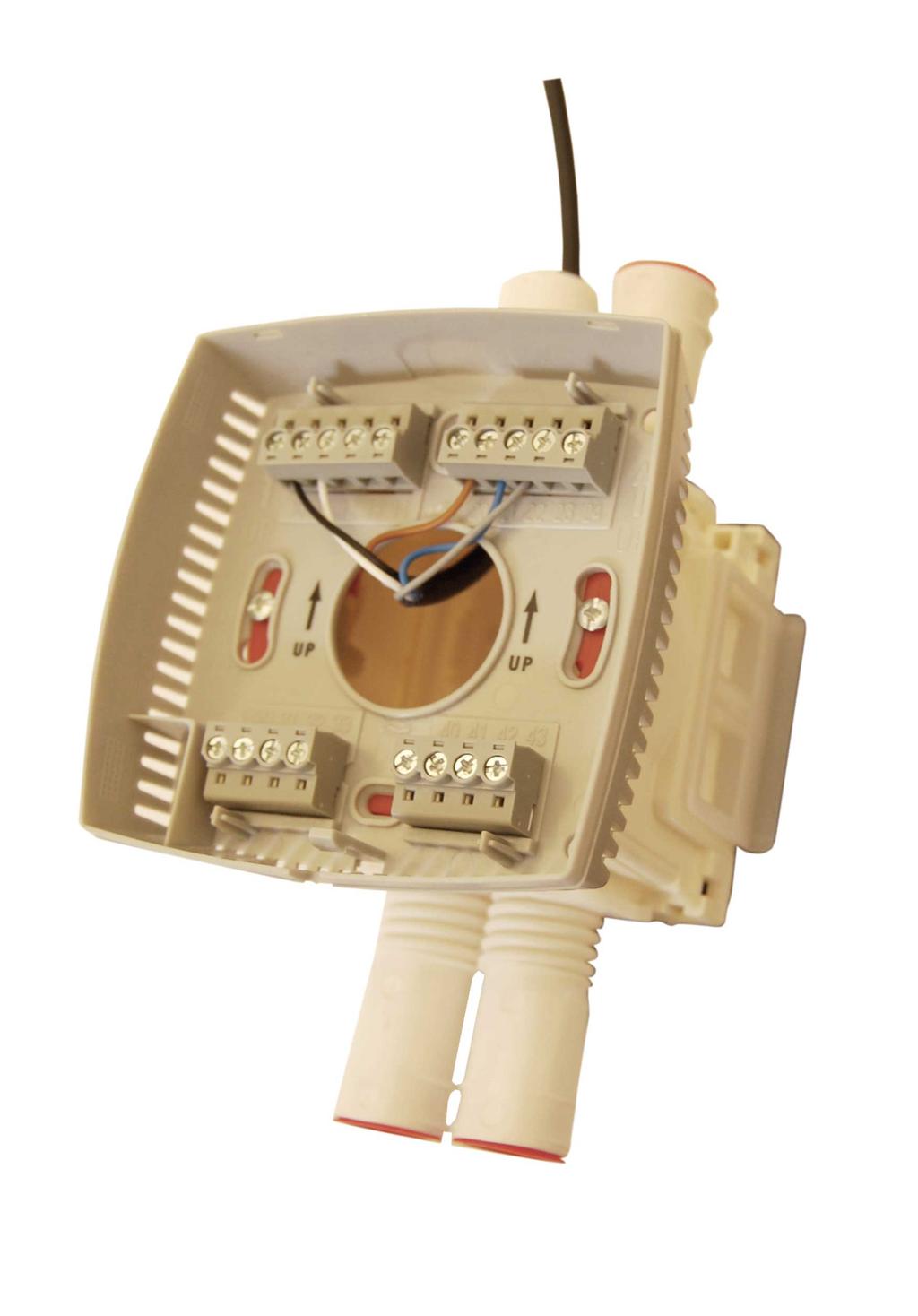


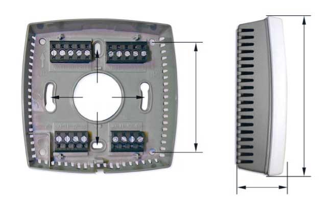
2 Installation instructions Ensure that the installation complies with local safety regulations Alternative 4. Dimensions Dimensions in mm 5.

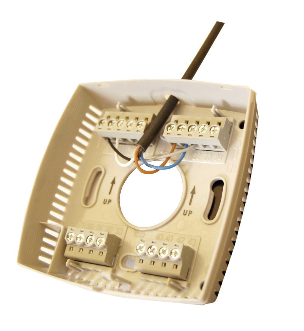
3 Wiring has been constructed to be as compact as possible. Therefore, the controller s communication input is not galvanically separated from the supply voltage. This means that it is important to keep G and G in order, as well as the communication input s A and B. All units that share the same transformer and communication loop must use the same transformer pole for G (terminal 1) and G (terminal 11). On the communication loop the A-terminal (terminal 4) should only be connected to another A-terminal and the Bterminal (terminal 43) to another B-terminal. Otherwise, there is great danger of short-circuit with damaged components as a result. Inputs AI UI CI DI Outputs DO UO 3 PT1-sensor,...5 C, accuracy +/-.1 C AI: PT1-sensor,...1 C, accuracy +/-. C or DI: see DI below s condensation detector, STRZ-16 Closing potential-free contact connected to +C in one end 4 V AC, max,5 A DO:4 V AC, max. A or O: V DC, max 5 ma +C, power output for DI only...4 V DC, max 1mA, short circuit protected
4 Terminal Designation G G 3 UO1 4 UO 3 AI1 31 UI1 3 DI1 33 DI/CI C AGnd A B GDO G UO3 Operation Supply voltage 4 V AC Supply voltage V No function. 4 V AC out common for DO. Internally connected to terminal 1, G. V common for UO. Internally connected to terminal 11, G. Output for VAV or EC-fan. For 1 V DC damper control/ec-fan. The damper actuator/ec-fan 1 V control signal terminal is connected to terminal, and its supply terminals to terminals 1 and 11.Make sure that the reference pole G is connected to the correct terminal on the actuator. Control of heating (FS) cooling or heating/cooling via change-over. For...1 V DC valve actuators, max 5 ma (FS). The valve actuator's 1 V control signal terminal is connected to terminal 3 and its supply terminals to terminals 1 and 11. Make sure that the reference pole G is connected to the correct terminal on the actuator. alternatively For a 4 V AC thermal actuator, max. A. The thermal actuator is connected between terminals 3 and, GDO. Control output heating or cooling (FS). For a...1 V DC valve actuator, max 5 ma (FS). The valve actuator s 1 V control signal terminal is connected to terminal 4 and its supply terminals to terminals 1 and 11. Make sure that the reference pole G is connected to the correct terminal on the actuator. alternatively For a 4 V AC thermal actuator, max. A. The thermal actuator is connected between terminals 4 and, GDO. For an external room sensor, PT1. Measuring range...5 C. The sensor is connected between terminals 3 and 41, AGnd. For switching between heating and cooling on a two-pipe system (change-over). A PT1-sensor is connected between terminals 31 and 41, AGnd. Measuring range:...1 C. alternatively For a potential-free contact. A potential-free contact is connected between terminals 31 and 4, +C. Occupancy detector. A potential-free contact is connected between terminals 3 and 4, +C. Closed contact corresponds to occupancy. alternatively Window contact (DI). A potential-free contact is connected between terminals 33 and 4, +C. Closed contact indicates closed window. See also the section Occupancy detector in the chapter Operating modes. condensation detector STRZ-16 (FS). The sensor is connected between terminals 33 and 41, AGnd. alternative alternatively Window contact (DI). A potential-free contact is connected between terminals 33 and 4, +C. Closed contact indicates closed window. 4 V DC out common for DI and UI (with digital function) Analogue ground, reference for AI and UI (with analogue function) RS-485-Communication A RS-485-Communication B 4
 Pressing on INCREASE increases the current setpoint by.5 C with each press up to the max.")

5 Display handling Set point The display has the following indications: In Occupied mode, the controller operates from a heating setpoint (FS = C), or a cooling setpoint (FS = 4 C) that can be changed using the INCREASE and DECREASE buttons. Auto/Man Current indication fan speed for the fan (, 1,, 3) Pressing on INCREASE increases the current setpoint by.5 C with each press up to the max. limit (FS = +3 C). Pressing on DECREASE decreases the current setpoint by.5 C with each press down to the min. limit (FS = -3 C). Forced ventilation Changeable value Occupancy Fan Switching between heating and cooling setpoints is done automatically in the controller depending on the heating and cooling requirement. indication Setpoint Indoor / Current room outdoor temp. temperature in C to one decimal point Fan control OFF: Unoccupied Open window RC-C3DFOC has a fan button. The speed is set with the fan button. When the fan button is pressed, the fan speed will step from the current speed to the next. The controller has the following positions: (also shows temperature) or Off STANDBY: COOL/HEAT: Shows if the unit indication Standby indication controls according to the heating (only OFF) SERVICE: or cooling setpoint Setting parameters Auto It is possible to set different parameter values in a parameter menu in the display, using the buttons on the controller. You change parameter values with the INCREASE and DECREASE buttons and confirm changes with the Occupancy button. I II III Automatic control of the fan speed to maintain desired room temperature. Fan Off. Manual position with low speed. Manual position with medium speed. Manual position with high speed. In operating modes Off and Unoccupied, the fan is stopped, regardless of the setting in the display. 5
6 Technical data Supply voltage Internal consumption Ambient temperature Storage temperature Ambient humidity Protection class Communication Modbus BACnet Communication speed Display Built-in temperature sensor Material, casing Weight Colour V AC, Hz.5 VA...5 C C Max 9% RH IP RS485 (EXOline or Modbus with automatic detection/change-over, or BACnet) 8 bits, 1 or stop bits. Odd, even (FS) or no parity MS/TP slave and master 96, 19, 384 bps (EXOline Modbus and BACnet) or 768 bps (BACnet only) LCD with background illumination NTC type, measuring range...5 C, accuracy ±.5 C at C Polycarbonate, PC 11 g Cover: Polar white RAL91 Bottom plate: Light gray This product conforms to the requirements of the EMC Directive 4/18/EC through product standards EN and EN RoHS This product conforms to the Directive 11/65/EU of the European Parliament and of the Council. Inputs External room sensor Change-over alt. potential-free contact Occupancy detector Condensation detector alt. window contact PT1-sensor, 5 C. Suitable sensors are STRZ-5 PT1-sensor, 1 C. Suitable sensor is STRZ-15 Closing potential-free contact. Suitable occupancy detector is STRZ-9. condensation detector STRZ-16 alt. Window contact STRZ-38 resp. potential-free contact Outputs Valve actuator, alt. thermal actuator or On/Off actuator (UO1, UO) Valve actuator Thermal actuator On/Off actuator Damper actuators (UO3) EC fan Control outputs 1 V, max 5 ma 4 V AC, max. A (time-proportional pulse output signal) 4 V AC, Max.. A Control Heating, cooling or VAV (damper) 1 output...1 V DC EC fan Actuator exercise Terminal blocks S = 3 hours interval Lift type for cable cross-section.1 mm Setpoint settings Basic heating setpoint Basic cooling setpoint Setpoint displacement C C ±...1 C (FS = ±3 C) 6
7 Configuration Activation of the different operating modes The controllers are configured via the display through setting the required parameters. See section Display handling/parameter menu. Different applications require different parameters to be set. Preset operating mode Operating modes Occupied is the preset operating mode. The operating mode is changed at the following events: When the Occupancy button is pressed (if the controller has an Occupancy button). Activation/deactivation of an occupancy detector on the digital input. There are five different operating modes: Off, Unoccupied, Stand-by, Occupied and Bypass. Occupied is the preset operating mode. It can be changed to Standby in the parameter menu in the display. The operating modes can be activated via a central command, an occupancy detector or the Occupancy button. CO value exceeded. Via central control, for example central time control, central booking system etc. Occupancy button Off Heating and cooling are disconnected. However, the temperature must not drop below the set minimum temperature ( setting (FS)=8 C). Operating mode Off is activated on open window. Unoccupied The room where the controller is placed is not used for an extended period, for example during holidays or long weekends. Both heating and cooling are disconnected within a temperature interval with configurable min/max temperatures (FS min=15 C, max=3 C). Stand-by The room is in an energy save mode and is not used at the moment. This can for example be during nights, weekends, evenings etc. The controller is prepared to change operating mode to Occupied if someone enters the room. Both heating and cooling are disconnected within a temperature interval around the applicable setpoint (FS heating setpoint value=-3 C, cooling setpoint=+3 C). Occupied The room is in use and is therefore in a comfort mode. The controller regulates the temperature around a heating setpoint (FS= C) and a cooling setpoint (FS=4 C). Bypass The temperature in the room is controlled in the same way as in operating mode Occupied. The output for forced ventilation is also active. Bypass is useful for example in conference rooms, where many people are present at the same time for a certain period of time. When Bypass has been activated by a press on the Occupancy button, the controller will automatically return to the preset operating mode (Occupied or Stand-by) after a configurable time (FS= hours). If an occupancy detector is used, the controller will automatically return to the preset operating mode after 1 minutes absence. 7
8 Shutdown Control states When the Occupancy button is held depressed for more than 5 seconds, the controller changes operating mode to Shutdown (Off/Unoccupied), regardless of the current operating mode. Via the display, you can configure which operating mode, Off or Unoccupied, should be activated on Shutdown. The factory setting is that Unoccupied is activated. can be configured for different controller modes/ control sequences: Heating Heating/Heating Heating/Cooling via change-over If you press the Occupancy button for less than 5 seconds when the controller is in operating mode Shutdown or the preset operating mode, the controller changes to operating mode Bypass. If you press the button for less than 5 seconds when the controller is in Bypass, it changes operating mode to the Preset operating mode. After a configurable time in Bypass (FS= hours), the controller returns to the preset operating mode. Heating/Cooling Heating/Cooling with VAV-control and forced supply air function Heating/Cooling with VAV-control Cooling Cooling/Cooling Heating/Cooling with change-over for cooling For handling of the Occupancy button in combination with central control, see the section Central control below. Occupancy detector For the control states, UO1 is used for the left control function and UO is used for the right control function. For control states where only one control function is active (Heating, Heating or cooling via the change-over function, and Cooling), only UO1 is used. Heating In control state Heating, the unit is always a heating controller and controls according to the heating setpoint plus/minus the setpoint displacement. The setpoint can be adjusted in the display. Heating or cooling via the change-over function For local control of the operating mode between the preset operating mode and Bypass, an occupancy detector is connected. When occupancy is indicated, the controller changes operating mode to Bypass. If you want to be able to enter the room temporarily without activating Bypass, for example to pick something up, you can configure a power up delay. This means that Bypass is not activated until the power-up delay has expired. The Bypass delay can be set to a value between and 6 minutes (FS= min). In Bypass on presence, there is a switch-off timer, which means that if there is no occupancy indication during this time (FS=1 min), the controller will return to the preset operating mode. Like control state Heating but with change-over function, I. e. when the change-over input is active, the controller becomes a cooling controller and regulates according to the basic cooling setpoint plus/minus the setpoint displacement. See more in the section Change-over. Heating/cooling with change-over for cooling A function for control of a heating battery on UO1 in sequence with change-over on UO is available. When this has been performed, the start sequence of UO1/UO is changed along with the limits for fan start. The change-over function will be used to switch between summer and winter mode. UO will be used as a cooling actuator in summer mode and as a heating actuator in winter mode. In summer mode, the will function as a regular heating/cooling controller. In winter mode, the will function as a heating/heating controller. UO will initiate first and UO1 second. The electrical heating battery connected to UO1 will start only if the ordinary heat battery on UO cannot meet the heating demand. When a heating demand exists, the output of UO is 1 % linear to the heating demand 48 % and UO1 1 % to the heating demand 5 1 %. When the heating demand is 48 5 % UO will always output 1 % and UO1 %. 8
9 Heating/Heating Cooling/Cooling Split output signal Split output signal In control mode Cooling/Cooling, the controller always functions as a cooling controller and controls according to the basic cooling setpoint plus the setpoint displacement. When the controller output signal reaches 5%, it is divided between two actuators. 48% of the signal is sent to actuator 1 and 5 1% of the signal is sent to actuator. See the figure below. Split output signal In control state Heating/Heating, the controller is always a heating controller and controls according to the basic heating setpoint plus the setpoint displacement. When the controller output signal reaches 5%, it is divided between two actuators. 48% of the signal is sent to actuator 1 and 5 1% of the signal is sent to actuator. See the figure below. Actuators Heating/Cooling In control state Heating/Cooling, the controller functions as a heating controller when the room temperature is lower than the basic heating setpoint plus half the neutral zone. The neutral zone is the difference in temperature between the heating setpoint and the cooling setpoint. When the room temperature exceeds this limit, the controller becomes a cooling controller. There is a hysteresis of.1 C when the controller changes from heating to cooling controller and vice versa. When the controller is heating, it regulates according to the basic heating setpoint plus the setpoint displacement, and when it is cooling according to the basic cooling setpoint plus the setpoint adjustment. can be used with two types of actuators: Analogue 1 V actuators Thermal actuators The actuator type is set via the parameter menu in the display. Analogue actuators The following output signals can be set for analogue actuators: 1 V (FS) 1 V 1 V 1 V Thermal actuators When thermal actuator control has been selected, this is controlled digitally with time proportional pulses via output UO. By pulsing, the opening degree of the actuator (and its valve) is varied. The period time (in seconds) is the sum of the on and off output times on the output. The period time is FS=6s. The controller varies the on and off output times proportionally depending on the output signal demand to the actuator. Actuator exercise Cooling All actuators are exercised. The exercise takes place at set intervals in hours (FS=3 hours interval). An opening signal is sent to the actuator for as long time as the run time has been configured. Then a closing signal is sent for as long time and the exercise is finished. In control state Cooling, the unit is always a cooling controller and controls according to the basic cooling setpoint plus the setpoint displacement. 9

10 is always the set speed. In the other operating modes, the fan is demand controlled. Fan control In it is possible to control a fan at the following speeds: Off, Low speed, Medium speed, High speed, Auto. The fan speed in the Auto position depends on the controller output signal and the settings for each speed. Auto control Manual control The fan can be manually controlled to work at any speed. On models with display, you press the fan button once and a fan symbol is lit for 1 seconds in the display. As long as the symbol is lit, you can change the fan speed with the INCREASE/DECREASE buttons. In auto mode, you can configure if the fan should be controlled by the heating output, the cooling output, or both the heating and cooling outputs. When the selected output exceeds the start value that has been set for each speed (FS speed 1=%, speed =6%, speed 3=1%), the fan is activated. It stops when the controller output signal drops below the set value minus the set hysteresis (FS=5%). When the fan speed changes, there is always a minimum delay (-3 s) between the inactivation of the output for the current speed and the activation of the output for the new speed. Only one fan speed output is defined at a time. Off/Unoccupied In operating modes Off and Unoccupied, the fan is stopped, regardless of the position of the fan switch or the setting in the display, on condition that the temperature is within the set temperature limits. If the temperature is not within the set temperature limits, the fan will be started in the corresponding Auto position, regardless of the settings. Figure 9. Fan button on models with display Figure 1. Alter fan speed The controller has the following positions: Auto I II III Automatic control of the fan speed to maintain desired room temperature. Fan Off. Manual position with low speed. Manual position with medium speed. Manual position with high speed. Manual setting of speed I-III means that the speed of the fan in operating modes Stand-by, Occupied and Bypass 1
 as for other fan models.")
11 EC fan control The has also a function to control EC fan. When this function is active, Y3 will follow Y1 and Y, respectively. It is possible to select whether the fan will run in Heating or Cooling, or in both Heating and Cooling. This setting is made using the same parameter (P5) as for other fan models. The function is activated by setting UO3 to Control of EC fan (P). It may be activated in control modes Heating, Heating/Heating, Heating or Cooling via change-over, Heating/ Heating or Cooling via change-over, Heating/Cooling, Cooling/Cooling and Cooling. The function will add a minimum limit to UO3, so that the fan will have sufficient supply voltage. The fan button will control the EC fan output to preset speeds and then offer feedback to the user through the fan segment displayed. When the fan button is depressed, it will step through the configured fan levels: 11
12 Functions description CO sensor and VAV control When the is to VAV control, the control mode is combined with a CO control function. In control mode Heating/Cooling with VAV-control, the CO concentration in the room will make the VAV damper, cooling output UO, open. The function is linear and the damper works between the configured min. flow (FS= %) and 1 %, depending on the CO concentration in the room. If the CO concentration drops below the configured min. limit, the damper will stay on the minimum allowed air flow. When the CO concentration rises, the damper will open linearly until reaching the configured CO max. value, at which point it will be 1 % open. Minimum limit on analogue 1 V actuator Min. Limit % % % % % When using a digital signal input (potential-free contact), closing the contact switches the change-over function and sets the heating output, UO1 alt. DO/DO3 (-T-models), to cooling. On open contact, the change-over function sets the heating output to heating. It is also possible to control change-over via a central command. See the variable list. Control states To activate the change-over function, control mode Heating or cooling via the change-over function should be configured. has an input for change-over. The input can be either of the type analogue Pt1-sensor or a closing contact connected to a digital input (FS=Pt1-input). The minimum limitation on the analogue output is only active in Bypass, Occupied and Standby. If the operating mode is Unoccupied or Off, the damper will be closed ( V on the analogue output). See table below: Operating mode Bypass Occupied Standby Unoccupied Off activated and the heating output, UO1 alt. DO/DO3 (Tmodels), is set to cooling. When the temperature exceeds C (FS) the change-over function is deactivated and the heating output is set to heating. The Pt1-sensor is mounted so that it senses the temperature on the feed wire to the battery. If the temperature drops below 18 C (FS), change-over is activated and the heating output, UO1 alt. DO/DO3 (-Tmodels), is set to cooling. When the temperature exceeds C (FS) the change-over function is deactivated and the heating output is set to heating. VAV output (Y) V V V V V When using a digital signal input (potential-free contact), closing the contact switches the change-over function and sets the heating output, UO1 alt. DO/DO3 (-T-models), to cooling. On open contact, the change-over function sets the heating output to heating. Many damper actuators have a working range of...1 V. This means that to set a minimum limitation of %, the min. limitation in the Regio will have to be set to 36 %. It is also possible to control change-over via a central command. See the variable list in page 14 of this manual. Forced ventilation The has no forced ventilation damper output exists, but the forced ventilation flag is activated when in Bypass mode. Condensation detector Special input CI Change-over Change-over is a function for installations with -pipe systems. It makes it possible to use the same pipe for both heating and cooling, depending on requirements during for example the summer (cooling output) and the winter (heating output). To activate the change-over function, control mode Heating or cooling via the change-over function should be configured. The Pt1-sensor is mounted so that it senses the temperature on the feed wire to the battery. If the temperature drops below 18 C (FS), change-over is When the condensation detector is activated, the cooling control is blocked and the controller is set in neutral position. When condensation ceases, the controller will start controlling from the neutral position. Window Contact When the window contact has been configured the regulator is set to normal operation when window is closed. If the window is open, the regulator is set in mode off, heating and cooling outputs are set to V and the frost protection function is activated. has an input for change-over. The input can be either of the type analogue Pt1-sensor or a closing contact connected to a digital input (FS=Pt1-input). There is a special input (CI) on controllers. This input is intended for s condensation detector, STRZ-16, and functions internally as a digital input, I. e. condensation or no condensation. 1
13 Frost protection STRA has built-in frost protection, which is activated when the controller is not in use. The frost protection prevents the temperature from dropping below 8 C. Return to normal fan speed and control occurs automatically when the room temperature exceeds 8 C. Parameter Settings is delivered with a number of factory settings. To acquire the desired function, the controller must be adapted to it s specific application. This is done through the parameter menu in the display. Applications may vary and incorrectly set parameters can effect the controller and application negatively. Be sure to set the necessary parameters relevant for your application. Parameter menu It is possible to set different parameter values in a parameter menu. The parameter menu is accessed by simultaneously holding the INCREASE and DECREASE buttons depressed for about 5 seconds and then pressing the INCREASE button twice. The Service indication will be displayed. First the display will show the parameter-number 1. Scroll between parameters by using the INCREASE and DECREASE buttons. Press the Occupancy button to select the desired parameter. The parameter number will be replaced by the parameter value. The value can be changed using the INCREASE and DECREASE buttons. If a button is held depressed the value will start scrolling, first slowly and then with increasing speed in 3 4 steps with 3 seconds between steps. Acknowledge/Regret To acknowledge and store a set parameter value, press the Occupancy button again, the display then returns to showing the parameter number. To retrieve the original value, i.e. the value before change, press the INCREASE and DECREASE buttons at the same time. The original value is shown on the display. Return After a certain time, about 1 minute, or when the INCREASE and DECREASE buttons are pressed at the same time while in the menu, the display returns to the normal view. Exit is shown on the display after the last parameter. The parameter menu is exited by pressing the Occupancy button while in Exit. Pressing on INCREASE goes to the first parameter and pressing on DECREASE goes to the last parameter.. 13
14 for Fan coils Quick guide to standard applications: Desired basic heating setpoint: 1 Desired basic cooling setpoint: Application control state: 11 Type of temperature sensor: 15 State of function UO1 (heating output): State of function UO (cooling output): 1 State output signal range, heating actuator: 9 State output signal range, cooling actuator: 3 Preset operating mode: 45 State operating mode by depressing occupancy button for 46 5 sec: Configuration of fan control 5 Start signal (%) for fan speed 1 51 Start signal (%) for fan speed 5 Start signal (%) for fan speed 3 53 Parameters The following parameters can be changed in the parameter menu (FS = setting): Parameter number Description FS Basic heating setpoint Basic cooling setpoint Neutral zone at standby, Heating setpoint = Basic sp. heating-3 by default Cooling setpoint = Basic sp.cooling+3 by default Heating setpoint at Unoccupied Cooling setpoint at Unoccupied Frost protection setpoint P-band for room controller I-time (s) for room controller The difference between the temperature in the room and the media temperature for change-over to cooling The difference between the temperature in the room and the media temperature for change-over to heating Control mode: =Heat, 1=Heat/Heat, =Heat or cooling via Change-over, 3=Heat/Cooling, 4=Heat/Cooling with VAV-control and forced ventilation, 5=Heat/Cooling with VAV control, 6=Cooling, 7=Cooling/Cooling, 9=Heat/Heat or Cooling via change-over (only available on models with fan control) Time in Bypass mode Disconnect timer with occupancy/unoccupancy Switch on delay for occupancy State connected sensor on AI1: =Internal sensor, 1=External room sensor State connected sensor on DI1: 1=Window contact, = No function, 3= Presence detector, 4=Change-over sensor State connected sensor on DI: 1=Window contact, =Condensation detection, 3=No function, 4=Change-over sensor State function of signal on UO1: =None, 1=Thermal actuator heat, =None, 3=Heating actuator...1v, 4=None, 5=On/off actuator heat, 6= None State function of signal on UO3: =None, 1=Forced vent. digital, =Analogue output (OEM), 3=None, 4=Ordinary analogue output, 5=None, 6=Control of EC fan State output signal range for Y3-actuators: = 1V, 1= 1V, =1 V, 3=1 V State output signal range for heating actuators: = 1V, 1= 1V, =1 V, 3=1 V State output signal range for cooling actuators: = 1 V, 1= 1 V, =1 V, 3=1 V Period time for heating actuator with thermal actuator Period time for cooling actuator with thermal actuator Run time for heating actuator with increase/decrease actuator Run time for cooling actuator with increase/decrease actuator Neutral zone for increase/decrease actuator Time in hours between exercise of heating actuator. Time in hours between exercise of cooling actuator. Hysteresis for on/off actuators and heating Hysteresis for on/off actuators and cooling Minimum limit for the heat output The fan will never stop: =OFF, 1=ON Select if setpoint or actual value is to be shown on display, =Actual, 1=Heating setpoint, =Cooling setpoint, 3=Average value of heating and cooling setpoint, 4=Only setpoint offset, 5= CO concentration in the room in ppm, 6=Heating setpoint +setpoint offset, 7=cooling setpoint +setpoint offset, 8=Average of heating and cooling setpoint+setpoint offset, 9=The calculated flow in the duct in l/s Highest permitted setpoint offset upwards Highest permitted setpoint offset downwards Preset operating mode: =Off, 1=Unoccupied, =Stand-by, 3=Occupied. Forced ventilation is not set in Occupied mode. State operating mode by depressing Occupancy button for 5 sec: =Off, 1=Unoccupied. Select operating mode for central control: =Off, 1=Unoccupied, =Stand-by, 3=Occupied, 5=No central control Min flow at cool output when control mode Heating/Cooling with VAV- control is selected Min flow at Y3 output when control mode Heating/Cooling/VAV is selected Max flow on Y3 output when control mode Heating/Cooling/VAV is selected and in heating mode C 4 C 3 C 15 C 3 C 8 C 1 C 3 s 3K 4K 3 1 min 1 min min s 6 s 1 s 1 s % 3 h 3 h K K 3 C 3 C % % Continued on next page 14
15 Parameter number Description FS Configuration of fan control: =No control, 1=The fan is controlled by heating requirement, =The fan is controlled by cooling requirement, 3=The fan is controlled by heating and cooling requirement Start signal in % for fan speed 1 on heating or cooling control Start signal in % for fan speed Start signal in % for fan speed 3 Hysteresis for start/stop of fans State number of speeds for fan Temperature compensation on AI1 Temperature compensation on UI1 Temperature compensation for internal room sensor Filter factor for analogue temperature inputs State NO/NC digital input 1: =NO (Normally open), 1=NC (Normally closed) State NO/NC digital input : =NO (Normally open), 1=NC (Normally closed) State NO/NC universal input :1 =NO (Normally open), 1=NC (Normally closed) Manual/Auto heating output signal: =Off, 1=Manual, =Auto Manual/Auto cooling output signal: =Off, 1=Manual, =Auto Manual/Auto Y3 forced ventilation output: =Off, 1=Manual, =Auto Manual/Auto control of change-over mode: =Heating control, 1=Cooling control, =Automatic change over depending on analogue sensor input or digital input Heating output signal in manual mode Cooling output signal in manual mode Controller Modbus address 3 5% 6% 1% 5% 3 C C C 1 % % set Parity bit Modbus communication: =No parity, 1=Odd parity, =Even parity Modbus time out for character (t1.5), in ms. Should be 1,5 times a character, i.e. at least ms. 3 ms Answer delay in Modbus (t3.5), in ms. Should be 3,5 times a character, i.e. at least 5 ms. 5 ms Selection of heating output function (NO/NC): =NC (Normally closed), 1=NO (Normally opened) Setpoint display at setpoint adjustment.: =The offset is shown in the display, 1=The active setpoint + offset is shown in the display. Heat or Cool is shown depending on whether heat or cool is active when entering the menu, =Heat setpoint + offset is shown in the display, 3=Cooling setpoint + offset is shown in the display Sequence order for Y and Y3: =Y activates before Y3, 1=Y3 activates before Y Forced ventilation, control function: =Not active, 1=Forced ventilation at 1% output of heat or cool, =Forced ventilation at 1% Cool output Operating mode at presence detection (DI1): 3=Occupied, 4=Bypass 4 EXOline PLA-address set EXOline PLA-address set Selection of cooling output functions (NO/NC): =NC, 1=NO State the connected sensor at AI: =None, 1 4=No function, 5= CO-sensor, 6=No function, 7= 1% (OEM-function), 8=Flow calculation, 5 9= 1 V Flow at V input in AI l/s Flow at 1 V input in AI 1 l/s Minimum runtime when calculating for change over 6s Alarm limit for high room temperature 4 C Alarm limit for low room temperature 15 C Continued on next page 15
16 Parameter number Description FS Activate presence if CO level is higher Deactivate presence if the CO level is lower than the limit minus this hysteresis Filter factor for CO-input CO-level at V CO-level at 1 V Min limit for VAV-damper at CO-control Max limit for VAV-damper at CO - control This parameter defines the protocol to be used: =EXOline/Modbus, 1=BACnet MS/TP, BACnet MS/TP MAC address: -17=master address, 18-54=slave address 116 Low 4 figures of the BACnet device ID High 3 figures of the device ID BACnet MS/TP Max master. COMbus speed: =96, 1=19, =384, 3=768 (only BACnet), COMbus reset. When activated (1) it resets the communication to default settings Min limit for EC fan (%) Max limit for EC fan (%) Model 16 Version Major 17 Version Minor 18 Version Branch 19 Revision 8 ppm 16 ppm. ppm ppm 6 ppm 8 ppm set (-99) set set 17 (deactivated) 1 % 1 % set (read only) set (read only) set (read only) set (read only) set (read only) 16
Pre-programmed room controller with display and communication
 revision 01 2014 RC-C3DOC Pre-programmed room controller with display and communication RC-C3DOC is a complete pre-programmed room controller from the Regio Midi series intended to control heating, cooling
RC-CDTO. Pre-programmed room controller with display, communication and three-point control
 revision 02 2016 RC-CDTO Pre-programmed room controller with display, communication and three-point control RC-CDTO is a complete pre-programmed room controller from the Regio Midi series intended to control
Pre-programmed room controller with display and communication
 revision 10 2017 RC-C3DOC Pre-programmed room controller with display and communication RC-C3DOC is a complete pre-programmed room controller from the Regio Midi series intended to control heating, cooling
Room controller STRA-17
 Room controller STRA-17 Application example Room 2 Room 3 Room 4 SCADA EXOline alt. RS485 Modbus Transformer STRZ-24 (Required component) STRA-17 is a preprogrammed room controller intended to control
RCF-230CD. Communicating room thermostat for fan-coil applications with on/off outputs
 revision 11 2013 RCF-230CD Communicating room thermostat for fan-coil applications with on/off outputs RCF-230CD intended to control heating and/or cooling in 2- or 4-pipe installations. Setpoint and fan
RCF-230CAD. Room controller with communication for fancoil applications with two analogue V DC outputs
 revision 04 2016 RCF-230CAD Room controller with communication for fancoil applications with two analogue 0...10 V DC outputs Intended to control heating and/or cooling in 2- or 4-pipe installations. Setpoint
RCF-230CAD. Communicating room controller for fan-coil applications with two analogue V DC outputs
 revision 01 2015 RCF-230CAD Communicating room controller for fan-coil applications with two analogue 0...10 V DC outputs RCF-230CAD intended to control heating and/or cooling in 2- or 4-pipe installations.
RCF-230CTD. Room controller for fan-coil applications with outputs for two thermal or one 3-position actuator or function for an electric heater
 revision 03 2012 RCF-230CTD Room controller for fan-coil applications with outputs for two thermal or one 3-position actuator or function for an electric heater RCF-230CTD is a room controller intended
RCF-230CTD. Built-in or external sensor The controller has a built-in sensor. Alternatively, the input for an external PT1000-sensor can be used.
 revision 01 2015 RCF230CTD Communicating room controller for fancoil applications with outputs for two thermal or one 3position actuator or function for an electric heater RCF230CTD is intended to control
WE TAKE BUILDING AUTOMATION PERSONALLY MANUAL RCF
 WE TAKE BUILDING AUTOMATION PERSONALLY MANUAL RCF Copyright AB Regin, Sweden, 2016 DISCLAIMER The information in this manual has been carefully checked and is believed to be correct. Regin, however, makes
AIAS. Technical description
 Fans Air Handling Units Air Distribution Products Fire Safety Air Curtains AIAS - and Efficient Heating Demand Products Controlled Tunnel Ventilation Fans 1 / 4 AIAS Technical description 2 / 9 AIAS -
FCU-4 FAN COIL CONTROLLER
 FCU-4 FAN COIL CONTROLLER BACnet Enabled Description The FCU-4 is designed to provide complete control of fan coil units. The FCU-4 incorporates all the inputs and outputs to ensure that this advanced
OP10. Pre-programmed, configurable controller for simple applications
 revision 10 2013 OP10 Pre-programmed, configurable controller for simple applications The Optigo OP10 range of controllers can be set to handle everything from temperature or humidity control to control
FCU-4 FAN COIL CONTROLLER
 FCU-4 FAN COIL CONTROLLER BACnet Enabled Description The FCU-4 is designed to provide complete control of fan coil units. The FCU-4 incorporates all the inputs and outputs to ensure that this advanced
EXOcompact. Third generation freely programmable controllers
 revision 1 013 EXOcompact Third generation freely programmable controllers Small, compact controller with different types of communication, with or without built-in display. EXOcompact can be used either
HLS34 Modbus FCU/VAV Controllers installation instructions
 HLS34 Modbus FCU/VAV Controllers installation instructions The HLS34 is specifically designed for individual room temperature and zone control applications. The controllers have built-in RS-485 channel
Communicative controller for VAV systems
 FCR015 Communicative controller for VAV systems Summary FCR015 is a communicative controller for heating and cooling panels and a VAV (variable air volume) damper. It measures temperature and CO 2 concentration
Evolution TH. Pre-configured controller with display, clock and communication. Evolution. Applications. TH version. Sensors
 Pre-configured controller with display, clock and communication Room controller for thermoregulation applications, equipped with rapid access buttons for the most common functions. Communication via RS485
Field selectable application type and room module series, via dip-switches on controller
 TUC03 Plus Configurable Terminal Unit Controller Product bulletin The TUC03 Plus configurable Terminal Unit Controller is specifically designed to provide an improved BACnet integration. It allows the
Suitable for a wide range of installations with wall-mount, flush-mount and hand-held remote control options.
 TUC03 Configurable Terminal Unit Controller Product Bulletin The TUC03 Configurable Terminal Unit Controller is designed specifically to provide direct digital control of terminal unit applications with
FCU-MULTI Modbus Fan Coil Unit Controller
 Product Sheet CT2.61 Controller Type FCU-MULTI FCU-MULTI Modbus Fan Coil Unit Controller FCU-MULTI is completely stand-alone operating room controller designed for room heating, cooling, ventilation, lighting
CONTENTS CONTROLLERS room controllers room units control units PRODUAL 3 CATALOGUE
 Catalogue 207 CONTENTS CONTROLLERS... 4 room controllers... 5 room units... 29 control units... 24 PRODUAL 3 CATALOGUE T U R KU I C T C ON T R OL L E R S Multifunctional controllers for optimal performance
TAC Xenta 101-VF. 3-Speed Fan Coil Controller. TAC Xenta
 TAC Xenta TAC Xenta 101-VF 3-Speed Fan Coil Controller TAC Xenta 101-VF is a zone controller intended primarily for fan coil applications with the ability to control fans with multiple speeds, with one
MiG2 CONTROLLERS. 2 & 4 Stage General Purpose Controllers, with Air-conditioning Facilities
 MiG2 CONTROLLERS 2 & 4 Stage General Purpose Controllers, with Air-conditioning Facilities The MiG2 controllers incorporate: 2 Inputs (Configurable as Resistive, 0 10V, 0 20mA or 4 20mA) 2 or 4 Relay Outputs
UC102 basic version with display and knob UC102BL version with display, knob and backlight UC102DK version without knob and display
 UC102 Communicative heating controller Summary UC102 is a communicative room heating controller with two inputs and one PWM output for control of a radiator or electrical heater. It can work autonomously,
Master room unit for RRV controllers
 2 722 Master room unit for RRV controllers 2 wire bus connection QAX850 Multifunctional, digital room unit for installer and end-user interface with RRV controllers. Use Use Application Room unit in combination
Semi Flush-mount Room Temperature Controllers with LCD
 3 076 RDF300, RDF300.02, RDF340 RDF400.01 Semi Flush-mount Room Temperature Controllers with LCD for 2-pipe, 2-pipe with el. heater and 4-pipe fan coil units for use with compressors in DX type equipment
Room Temperature Controller
 3 023 Room Temperature Controller for four-pipe fan coil units RCC30 Outputs for on / off valve actuators Outputs for three-speed fan Control depending on room or return air temperature Operating modes:
Modbus Integration Integration for Modbus Functionality for VTR8300 Series
 Modbus Integration Integration for Modbus Functionality for VTR8300 Series Building Management System *For data visualization and analysis Modbus Controller VT8000 Series room controllers 2 TABLE OF CONTENTS
SE7600E Series Application Guide
 SE7600E Series Application Guide Schneider Electric SE7600E Series RTU Controller with IAQ Control Application Guide CONTENTS Solution Overview 2 Product Overview 3 Features & Benefits 3 System Overview
Room Temperature Controller
 3 023 Room Temperature Controller for four-pipe fan coil units RCC30 Outputs for on / off valve actuators Outputs for three-speed fan Control depending on room or return air temperature Operating modes:
Room Temperature Controllers
 3 021 Room Temperature Controllers for two-pipe fan coil units RCC10 Output for on / off valve actuator Outputs for three-speed fan Control depending on the room or return air temperature (RCC10) Automatic
UCU Room Display. Operation Modes. Features. Applications DATASHEET
 DATASHEET UCU Room Display The UCU Room Display provides dedicated visually appealing Room Control display for use with UCU10FC/K Unitary Controller. The display allows the user to view and adjust selected
O P T I G O R E A D Y - S T E A D Y - G O Optigo OP5U Manual Copyright AB Regin, Sweden, 2012
 O P T I G O R E A D Y - S T E A D Y - G O Optigo OP5U Manual Copyright AB Regin, Sweden, 2012 DISCLAIMER The information in this manual has been carefully checked and is believed to be correct. Regin however,
MOD-RI Room Interface Modules with Modbus
 Product sheet MOD3.00 Type MOD-RI MOD-RI Room Interface Modules with Modbus The MOD-RI are room interface modules designed to provide room control interface for the building management systems. The MOD-RI
7-day room temperature controller
 s 2 208 7-day room temperature controller Heating applications REV34.. Mains-independent, battery-operated room temperature controller featuring user-friendly operation, easy-to-read display and large
ExactLogic BACnet Communicating Zone Damper EXL01710 Sequence Datasheet
 ExactLogic BACnet Communicating Zone Damper EXL01710 Sequence Datasheet DataSheet ev 1.12.302/4.3 October 27, 2014 Operating Sequence Standard Occupied During normal occupied operation the display will
LLR-MOD Modbus Light Level and Occupancy Sensor
 Product sheet SN1.418 Type LLR-MOD LLR-MOD Modbus Light Level and Occupancy Sensor The LLR-MOD sensors are designed to measure Light Level (LUX) in the room spaces and have built-in RS485 Modbus communication
Temperature controller Ducted systems
 2 725 Temperature controller Ducted systems Standard model without zoning functions RRV851 Multifunctional controller used for central control of ducted HVAC systems in combination with a QAX850 master
ExactLogic BACnet Communicating Pressure Dependent VAV Damper Control with Heat EXL01820 Sequence Datasheet
 ExactLogic BACnet Communicating Pressure Dependent VAV Damper Control with Heat EXL01820 Sequence Datasheet DataSheet ev 1.12.307/4.0 June 14, 2018 Operating Sequence Standard Occupied During normal occupied
Small distributed I/O module
 MLIO Summary Application Function Small distributed I/O module Small I/O module MLIO is a microprocessor-controlled, communiccative module for installation outside the control panel. It is used for topologies
RXTP ROOM TEMPERATURE
 ROOM TEMPERATURE CONTROLLER WITH PI CONTROL Mounting and operating instructions Table of contents SAFETY AND PRECAUTIONS 3 PRODUCT DESCRIPTION 4 ARTICLE CODES 4 INTENDED AREA OF USE 4 TECHNICAL DATA 4
CCM-204 MULTI-PURPOSE TEMPERATURE CONTROLLER
 CCM-204 MULTI-PURPOSE TEMPERATURE CONTROLLER BACnet Enabled C-037 08/12 DESCRIPTION The BACnet enabled CCM-204 Multi-Purpose temperature controller is designed to offer complete control flexibility for
CDR Room CO 2 and Temperature Sensor with Modbus
 Product sheet SN1.404 Type CDR-MOD CDR-MOD Room CO 2 and Temperature Sensors with Modbus The CDR-MOD sensors are designed to detect carbon dioxide concentration and temperature in the room spaces and have
OEM. Room unit QAA822 with2- wire interface. Building Technologies CLIMATIX TM. For use with Climatix controllers
 OEM CLIMATIX TM Room unit QAA822 with2- wire interface For use with Climatix controllers Remote control of air conditioning unit Mandík Measurement of the room temperature Buttons for starting, setting
RXTH DUAL ROOM SENSOR / SWITCH
 DUAL ROOM SENSOR / SWITCH FOR TEMPERATURE AND RELATIVE HUMIDITY Mounting and operating instructions Table of contents SAFETY AND PRECAUTIONS 3 PRODUCT DESCRIPTION 4 ARTICLE CODES 4 INTENDED AREA OF USE
TLR-D42 with OPA-D42 Intelligent PI fan coil controller for modulating actuators. Cabinet mounted base, wall mounted operation terminal.
 TLR-D42 with OPA-D42 Intelligent PI fan coil controller for modulating actuators. Cabinet mounted base, wall mounted operation terminal. Features Temperature control for 2-pipe and 4-pipe fan coil systems.
R7426A TEMPERATURE CONTROLLER WITHOUT REAL-TIME CLOCK. MicroniK 200. Order Numbers
 MicroniK 200 Fig. 1. Temperature controller GENERAL The R7426A temperature controller covers all space, air or water flow temperature applications within the selectable control range of 0...50 C (LOw range)
Constant & Variable air volume controllers
 Fans Air Handling Units Air Distribution Products Fire Safety Air Curtains and Heating Products Tunnel Fans Constant & Variable air volume controllers Air volume the smart way 2 Systemair Spread the secret
TER-MOD Active Room Temperature Sensors (Controllers) with Modbus
 with Modbus") Product sheet TER Type TER-MOD TER-MOD Active Room Temperature Sensors (Controllers) with Modbus The TER-MOD active sensors are designed to detect temperature in the room spaces and have built-in RS485
Product sheet TER Type TER-MOD TER-MOD Active Room Temperature Sensors (Controllers) with Modbus The TER-MOD active sensors are designed to detect temperature in the room spaces and have built-in RS485
Measure & Control Temperature & CO2 levels with analog & digital I/O
 MADE IN OZ HTC-DIGITAL-LCD PROGRAMMABLE TEMPERATURE CONTROLLER c/w YEARLY PROGRAMMABLE TIME SWITCH COMPATIBLE WITH A WIDE RANGE OF SENSORS ROOM O/A WALL DUCT PIPE Use Features Measure & Control Temperature
Universal Controller
 3 342 Universal Controller For comfort control in HVAC & R-Systems Standalone electronic universal controller with P or PI response Operating voltage in accordance to type AC 24 V Control application selectable
Control system. Type FSL-CONTROL II. Modular, stand-alone room control system, specially for decentralised ventilation systems (with bus communication
 X X testregistrierung Control system Type Central BMS interface DCP-FSL II-Stand-alone Pressure independent control valve Straight-way valve Modular, stand-alone room control system, specially for decentralised
Non-communicating room controllers
 3 882 DESIGO RXA Non-communicating room controllers RXA29.1 For fan-coil systems The RXA29.1 room controller are used for temperature control in individual rooms. For 2-pipe or 4-pipe fan-coil systems,
RXB10.1. Room controller. Siemens Building Technologies Building Automation DESIGO RXB. for chilled ceilings and radiators with EIB bus communication
 3 870 DESIO RXB Room controller for chilled ceilings and radiators with EIB bus communication RXB10.1 The RXB10.1 controller is used for temperature control in individual rooms: For chilled ceilings and
TAC Xenta 121-FC Programmable Fan Coil Application
 TAC Vista TAC Xenta 121-FC Programmable Fan Coil Application TAC Xenta 121-FC is an easily programmable controller intended for both 2-pipe and 4-pipe applications, with or without re-heat. It can be configured
Supplementary operating instructions for your air curtain system Controller TMC 500
 Supplementary operating instructions for your air curtain system Controller TMC 500 (Translation of the original) Serial number: Year: Please quote this number when contacting customer service! Date 08.04.2016
Semi flush-mounted room temperature controllers with LCD
 s 3 077 RDD310 RDE410 Semi flush-mounted room temperature controllers with LCD For heating systems RDD310 RDE410 RDD310 and RDE410 features: Operating voltage AC 230 V 2-position control with On / Off
RHR-MOD Combined Room Temperature and Humidity Sensors (Controllers) with Modbus
 with Modbus") Product sheet SN1.411 Type RHR-MOD RHR-MOD Combined Room Temperature and Humidity Sensors (Controllers) with Modbus The RHR-MOD sensors are designed to detect relative humidity and temperature in the room
Product sheet SN1.411 Type RHR-MOD RHR-MOD Combined Room Temperature and Humidity Sensors (Controllers) with Modbus The RHR-MOD sensors are designed to detect relative humidity and temperature in the room
Technical data sheet
 ZoneEase VAV Cloud VAV Controller set with Room Unit of Choice and Integrated pressure sensor, controller and damper actuator for pressure-independent temperature control VAV, Simple VAV and Demand Control
EYE 200: DDC single-room controller, ecos200
 Product data sheet 94.200 EYE 200: DDC single-room controller, ecos200 How energy efficiency is improved Individual unitary control, fan coil units, chilled-beam control system, etc. Features Part of the
Semi flush-mounted room temperature controllers with LCD
 s 3 077 RDD310 RDE410 Semi flush-mounted room temperature controllers with LCD For heating systems RDD310 RDE410 RDD310 and RDE410 features: Operating voltage AC 230 V 2-position control with On / Off
Corrigo E. Version 3.0 (ventilation), 3.0 (heating), 1.1 (boiler). Controllers for heating, boiler and ventilation applications in buildings.
, 3.0 (heating), 1.1 (boiler). Controllers for heating, boiler and ventilation applications in buildings.") revision 03 2011 Corrigo E Version 3.0 (ventilation), 3.0 (heating), 1.1 (boiler). Controllers for heating, boiler and ventilation applications in buildings. Pre-programmed with all applications and languages
revision 03 2011 Corrigo E Version 3.0 (ventilation), 3.0 (heating), 1.1 (boiler). Controllers for heating, boiler and ventilation applications in buildings. Pre-programmed with all applications and languages
BACnet Product Overview
 BACnet Product Overview Comfort and energy-saving of a HVAC system are all about control. With networking devices, you can monitor and control your equipment via a communication system anywhere and anytime
LM24A-MOD. Cable 1 m, 6 x 0.75 mm 2 RJ12 socket
 echnical data sheet Damper actuator for Modbus for adjusting air dampers in ventilation and air conditioning systems in buildings orque 5 Nm Nominal voltage AC/DC 4V Communication via Modbus RU (RS-485)
EY-EM : Remote I/O module, ecolink
 EY-EM 510...512: Remote I/O module, ecolink510...512 How energy efficiency is improved Optimum adjustment to applications by means of module technology. Reduction in wiring Features Part of the SAUTER
CDR-RH Room CO 2, Temperature and Humidity Sensors (Controllers)
") Product sheet SN1.401 Type CDR-RH CDR-RH Room CO 2, Temperature and Humidity Sensors (Controllers) CDR-RH sensors are designed to detect carbon dioxide concentration, relative humidity and temperature
Product sheet SN1.401 Type CDR-RH CDR-RH Room CO 2, Temperature and Humidity Sensors (Controllers) CDR-RH sensors are designed to detect carbon dioxide concentration, relative humidity and temperature
TC-8900 Controller Units with PM-8900 Power Modules
 European Electronic Controls Catalogue Catalogue Section F Product Bulletin PM-8900 Issue date 06 2000 TC-8900 Controller Units with PM-8900 Power Modules Introduction TC-8900 is a family of analogue controllers,
Networkable Dual Duct VAV Controller Specification and Installation Instructions
 Controller Models EVCBM14NIT2S (Master controller / 2 TRIACs) EVCS14N (Slave controller) TRL Series Thermostat TRL24 (Room Sensor: Temp) TRLH24 (Room Sensor: Temp and %RH) TRLG24 (Room Sensor: Temp and
Application program: description and examples
 F a n C o i l U n i t C o n t r o l l e r F a n C o i l 4 9 5 5 1 Application program: description and examples Woertz AG Electrotechnical accessories, installation systems Hofackerstrasse 47, P.O. Box
RTT2 ROOM TEMPERATURE SWITCH. Mounting and operating instructions
 Mounting and operating instructions Table of contents SAFETY AND PRECAUTIONS PRODUCT DESCRIPTION ARTICLE CODES INTENDED AREA OF USE TECHNICAL DATA STANDARDS OPERATIONAL DIAGRAMS WIRING AND CONNECTIONS
Electrical data Nominal voltage AC/DC 24 V Nominal voltage frequency
 echnical data sheet LR24A-MOD Communicative rotary actuator for ball valves orque motor 5 Nm Nominal voltage AC/DC 24 V Control modulating,, hybrid mode Conversion of sensor signals Communication via BACnet
ExactLogic BACnet Communicating Thermostat EXL01716 Sequence Datasheet Duel Deck VAV
 ExactLogic BACnet Communicating Thermostat EXL01716 Sequence Datasheet Duel Deck VAV DataSheet ev 1.12.302/4.1 June 26, 2018 Operating Sequence Standard Occupied Thermostat occupancy can be set from a
DUKE UNIVERSITY DESIGN & CONSTRUCTION STANDARDS
 1 25 95 00 Integrated Automation Control Sequences for HVAC GENERAL The HVAC operational sequences in this guideline are commonly used by Duke University. They are being provided as a preferred design
NT50 Series RS485 Modbus RTU Networking LCD Fan Coil Thermostat
 NT50 Series RS485 Modbus RTU Networking LCD Fan Coil Thermostat Features Modern Appearance Stylish rotary dial and buttons Large LCD with backlight Support Modbus RTU protocol Support standalone operation
7-day room temperature controller
 s 2 205 7-day room temperature controller Heating or cooling applications REV24.. Mains-independent, battery-operated room temperature controller featuring user-friendly operation, easy-to-read display
EXOcompact. Freely programmable controller
 flik plats revision 0 710 12 2005 EXOcompact Freely programmable controller A small and compact controller in three different I/O sizes and with different kinds of communication, with or without internal
RTD-RA. realtime. Installation Instructions. English A B. Installation Instructions Control Systems LEDS ALL DIMENSIONS IN MM
 RTD-RA Installation Instructions 37.50 LEDS 4 3 2 1 D English Installation Instructions 80.00 80.00 ALL DIMENSIS IN MM C realtime Control Systems A B LEDS 4 3 2 1 D S21 J3 J6 1 2 3 4 J5 5 6 7 0V S1 0V
Installation and Operation. Tracer MP501 Controller CNT-SVX08B-EN
 Installation and Operation Tracer MP501 Controller CNT-SVX08B-EN Installation and Operation Tracer MP501 Controller CNT-SVX08B-EN April 2005 CNT-SVX08B-EN Tracer MP501 Controller Installation and Operation
Weekday / weekend room temperature controller
 s 2 203 Weekday / weekend room temperature controller Heating applications REV17.. Mains-independent, battery-operated room temperature controller featuring user-friendly operation, easy-to-read display
Room unit with PPS2 interface
 1 626 Room unit with PPS2 interface for use with: controllers with a PPS2 interface QAA88.3 Room temperature measurement Key buttons for adjustment of the room temperature setpoint Key buttons for operating
FANCOIL CONTROLLER UNIT TC17B01KNX. Product Handbook
 FANCOIL CONTROLLER UNIT TC17B01KNX Product Handbook Product: TC17B01KNX Description: FANCOIL CONTROLLER UNIT Document Version: 1.2 Date: 09/09/2016 1/37 INDEX 1. General Introduction... 4 2. Product and
Compact universal controllers
 7 867 Compact universal controllers RWF55... The RWF55 is used mainly for controlling the temperature or pressure in oil- or gas-fired heating plants. If the relevant parameters are set, the RWF55 can
EY-RU : Room operating unit, ecounit
 Product data sheet 94.040 EY-RU 341...346: Room operating unit, ecounit341...346 How energy efficiency is improved Individual setting of occupancy and absence as well as a room setpoint correction and
RST ROOM TEMPERATURE TRANSMITTER. Mounting and operating instructions
 Mounting and operating instructions Table of contents SAFETY AND PRECAUTIONS 3 PRODUCT DESCRIPTION 4 ARTICLE CODES 4 INTENDED AREA OF USE 4 TECHNICAL DATA 4 STANDARDS 4 OPERATIONAL DIAGRAM 5 WIRING AND
VTR8300 User Interface Guide VTR8300 Room Controller Series
 VTR8300 User Interface Guide VTR8300 Room Controller Series CONTENTS Home Screen Display 2 How to Enter Setup Screen 3 Setup Screen Display 3 Network Settings 4 ZigBee Network Settings 4 BACnet Network
SE7600E Series Application Guide
 Schneider Electric SE7600E Series RTU Controller with IAQ Control Application Guide CONTENTS Solution Overview 2 Product Overview 3 Features & Benefits 3 System Overview & Architecture 4 Models Available
Viconics VT76x6W Water-source Heat Pump Controllers Engineering Guide Specification
 Viconics VT76x6W Water-source Heat Pump Controllers Engineering Guide Specification General The VT76xxW series is designed for single-stage and multi-stage control of water source heat pumps with dedicated
Temperature Controller (Heat Pumps)
") 3 347 Temperature Controller (Heat Pumps) For comfort control in HVAC & R systems Standalone electronic controller Programmable controller with preconfigured applications Three universal inputs for Ni1000,
3 347 Temperature Controller (Heat Pumps) For comfort control in HVAC & R systems Standalone electronic controller Programmable controller with preconfigured applications Three universal inputs for Ni1000,
DESIGO RX Individual room controllers. for fan-coil systems, chilled ceilings and radiators, with LONMARK-compatible bus communications
 3 834 DESIO RX Individual room controllers for fan-coil systems, chilled ceilings and radiators, with MARK-compatible bus communications RXC20.1 RXC21.1 The RXC20.1 and RXC21.1 controllers are used for
Modbus RTU/TCP GOLD RX/PX/CX/SD, GENERATION C/D Applicable to program version 1.05 and newer versions
 Modbus RTU/TCP GOLD RX/PX/CX/SD, GENERATION C/D Applicable to program version 1.05 and newer versions Overview ModBus can access single addresses or multiple addresses simultaneously; either reading or
/ 2CKA001473B KNX Technical Reference Manual ABB i-bus KNX. Room temperature controller with display 6108/18-500
 1473-1-8913 / 2CKA001473B8913 23.03.2016 KNX Technical Reference Manual ABB i-bus KNX Room temperature controller with display 6108/18-500 Table of contents Table of contents 1 s on the instruction manual...
Microprocessor based Temperature / CO2 Controller c/w 365 Day Time Switch & Modbus Communication.
 HTC-DIGITAL-LCD Microprocessor based Temperature / CO2 Controller c/w 365 Day Time Switch & Modbus Communication. Features Use Australian Made and designed LCD 2 X 16 Character Backlit Display Five Programmable
MOD-IO9 Modbus Input / Output Modules, Wall Mounted
 Product sheet MOD3.9 Type MOD-IO9 MOD-IO9 Modbus Input / Output Modules, Wall Mounted MOD-IO9 and MOD-IO9-AI have been designed to be a compact wall mounted Modbus RTU input and output module. The module
Weekday / weekend room temperature controller
 s 2 203 Weekday / weekend room temperature controller Heating applications REV17.. Mains-independent, battery-operated room temperature controller featuring user-friendly operation, easy-to-read display
Andover ContinuumTM. b3850 Series Terminal Controllers
 TM b3850 Series Terminal Controllers The TM b3850 series controllers are native BACnet controllers that communicate on an RS-485 field bus as Master devices using the MS/TP BACnet protocol. 02 Features
TRACKER 240 SERIES. Load Cell and Weighing Indicators. A Precision Measurement Instrument with Outstanding Features
 TRACKER 240 SERIES Load Cell and Weighing Indicators A Precision Measurement Instrument with Outstanding Features TRACKER 240 SERIES INDICATORS Ratiometric Measurement Tare and Auto Transducer Excitation
Millennium Simplicity Elite Parameter Points and Quirks
 Millennium Simplicity Elite Parameter Points and Quirks How to access, view and change parameter settings Program Button Test Reset UP Alarms Change Data Address Down 1. Push the Program button once. The
RТTH DUAL ROOM SWITCH
 DUAL ROOM SWITCH FOR TEMPERATURE AND RELATIVE HUMIDITY Mounting and operating instructions Table of contents SAFETY AND PRECAUTIONS PRODUCT DESCRIPTION ARTICLE CODES INTENDED AREA OF USE TECHNICAL DATA
RAMSES D GB F NL. Installation and operating instructions Room thermostat. RAMSES 832 top2
 309 358 04 RAMSES RAMSES 811 top2 RAMSES 831 top2 811 9 132 831 9 132 RAMSES 812 top2 RAMSES 832 top2 812 0 132 832 0 132 GB Installation and operating instructions Room thermostat D GB F E I NL RAMSES