Operating manual GTL 142 GTL 152. Temperature probe. Please keep the manual for future use.
|
|
|
- Scott Lane
- 6 years ago
- Views:
Transcription


1 Operating manual Temperature probe GTL 142 GTL 152 Please keep the manual for future use. L01.0.1X.6C-02
2 GREISINGER electronic GmbH Hans-Sachs-Str Regenstauf Germany Fon +49(0) Fax Table of contents Page 1 Intended use (application area) Safety signs and symbols Safety instructions Product liability and warranty Standards and directives Approval Product description Scope of supply Ambient temperature Design of temperature probe Type label Mounting and electrical installation Mechanical mounting Welding instructions Electric installation Connection Operating elements and functions Operation (with integrated on-site-display) Configuration of device with button (with integrated on-site display) Configuration of device with GTL - Configuration tool Commissioning, maintenance and servicing Technical data Mechanical design / dimensions Ordering code Accessories Device transport and storage Returns Disposal EC conformity certificate Imprint /16

3 1 Intended use (application area) The chapter Product description provides details on the application area. The operational safety of the device is only ensured for the intended use according to this manual. Any changes not described in this manual must only be done by personnel authorized by the manufacturer due to security and warranty aspects. Unauthorized reconstructions or changes are expressly prohibited. Application-specific hazards may be provoked by improper or not intended use of this device. The device must not be used in potentially explosive areas or for security-related components according to SIL. General safety notices, application This manual must be kept at a place at which it can be looked at any time by the qualified personnel. All procedures described in this manual must be done only by skilled and authorized personnel with adequate protective clothing. All rights reserved. 1.1 Safety signs and symbols Warnings are labeled in this document with the followings signs: GEFAHR Caution! This symbol warns of imminent danger, death, serious injuries and significant damage to property at non-observance. Attention! This symbol warns of possible dangers or dangerous situations which can provoke damage to the device or environment at non-observance. Note! This symbol point out processes which can indirectly influence operation or provoke unforeseen reactions at non-observance. Table 1 3 / 16
4 GREISINGER electronic GmbH Hans-Sachs-Str Regenstauf Germany Fon +49(0) Fax Safety instructions Read this document carefully before you use the device. Assure that the device is suitable for the desired application The operator is responsible for interference-free operation. He must assure the accordance to required job safety measures of the current applicable regulations during the whole period of application. GEFAHR 1.3 Product liability and warranty Disclaimer: The content of the manual is checked for conformity to the described device. However, differences cannot be excluded completely. Therefore we cannot guarantee full conformity. All information of this manual are continuously checked and necessary corrections are included to the following editions. Technical modifications are reserved. Additionally all claims are subject to the latest General Terms of Delivery for Products and Services of the Electrical Industry (ZVEI). Please note that Greisinger electronic cannot check or repair devices without the specified, fully completed form (see chapter 8, Returns ). 1.4 Standards and directives Conform to EMVG 2004/108/EG CE-conformity EN : Vibration test EN Approval EHEDG Conform to FDA and 3A 4 /16
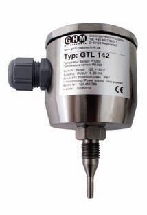
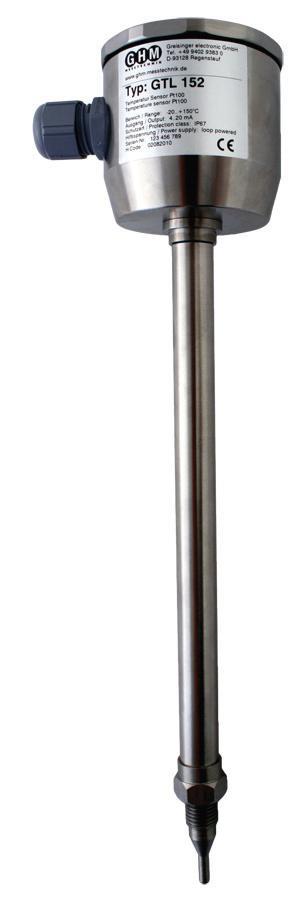
5 2 Product description The GTL 142 and GTL 152 are temperature probes with or without transmitter for collecting and converting temperature input signals. 2.1 Scope of supply Temperature probe This operating manual Possibly further documents 2.2 Ambient temperature Restrictions dependent on ambient temperature (recommended values) Max. ambient temperature Max. process temperature Note up to 20 C 150 C up to 40 C 130 C 140 C if t 30min up to 60 C 110 C 120 C if t 30min Note: The max. permitted process temperature depends on the ambient temperature and must not be exceeded to ensure faultless functioning. 2.3 Design of temperature probe GTL 142 e housing type label wrench size SW17 process thread sealing edge to process Figure 1 sensor tip 5 / 16


6 GREISINGER electronic GmbH Hans-Sachs-Str Regenstauf Germany Fon +49(0) Fax Type label The type label (Fig. 2) provides important identification data: Type and article name Technical data Serial number 3 Mounting and electrical installation 3.1 Mechanical mounting Figure 2 The correct seating of the device, correct function and sealing of the connection can only be ensured by using the GHMadapt accessories. The device is not suitable for use in abrasive materials. No additional sealing material (e.g. Teflon tape) must be used on the sealing cone or on the thread. Use a suitable welding mandrel for the correct installation of GHMadapt welded sleeves. The switch must not be sued as a welding aid. Installation direction of the welded sleeves (Fig. 3 and 4). The marking shows the position of the M12 connector or cable screw fitting. Line marking on the sleeve Figure 4 Figure 3 6 /16
 Note the correct sequence of the tacking 3. Screw in the welding aid (see Product information GHMadapt AMH121, -122, -123) 4.")
7 3.2 Welding instructions Welding in tanks: Figure 5 1. Drill a hole with the outer diameter of the sleeve, max. tolerance +0.2 mm 2. Tack the sleeve in place at 4 points (Fig. 5) Note the correct sequence of the tacking 3. Screw in the welding aid (see Product information GHMadapt AMH121, -122, -123) 4. Weld the sections between the tacks 4 sections for thread M12 Welding in pipes: In addition to the APH pipe system, ball sleeves or sleeves with a welding shoulder for pipes with collars are also available. Note the maximum permissible tightening torque when mounting! Remove the switch before carrying out any welding work on the tank. This will avoid damage to the electronics due to inductive coupling. The case must not be used for screwing in! Tightening will result in damage to the electronics. Use the hexagonal provided for screwing in the switch. In order to avoid excess heating or warping of the sleeve during the welding process, allow a pause between the individual sections so that the sleeve can cool down Instructions for installation to EHEDG The installation without gap and dead space is based on the hygienic elastomer-free sealing principle. For this purpose, we offer corresponding fitting accessories such as sleeves and adapters with the GHMadapt sealing principle. 7 / 16
8 GREISINGER electronic GmbH Hans-Sachs-Str Regenstauf Germany Fon +49(0) Fax Electric installation GEFAHR The device must be installed only by a qualified electrician. The national and international regulations for the installation of electrical systems of the relevant operator country apply. Power supply according to DIN EN , SELV, PELV. 3.4 Connection For electric connection: Cable junction M12-plug With transmitter Without transmitter Figure 6 Figure 7 For electric connection: Cable gland M16x1.5(PG) With transmitter Without transmitter Figure 8 Figure 9 8 /16

9 4 Operating elements and functions 4.1 Operation (with integrated on-site display) min/max Press button (Fig. 10) shortly: The following points are displayed one after another: Display Duration Lo 0.5s Min value 1.5s Hi 0.5s Max value 1.5s blank 0.5s Current value Figure 10 Press button for 2s while the device still displays Lo, Hi or the corresponding values to delete min/max values. Confirmation: display of CLr 4.2 Configuration of device with button (with integrated on-site display) To configure the device s functions proceed as follows: Switch the device on Press button 4s until the first parameter rang is displayed o Press button shortly to select next parameter o No button-press >5s: restart, data is saved Press button for 2s until the current parameter value is displayed o Press button shortly to set parameter value o No button-press >2s: back to parameter selection Parameters adjustable via button Parameter Display Parameter value Meaning Temperature range rang r C r C r C r C r C Filter FiLt off no filter 1 filter stage 1 2 filter stage 2 3 filter stage 3 Default state of output da.er Lo 3.75 ma Hi 22 ma Backlight bl off off on on 9 / 16
10 GREISINGER electronic GmbH Hans-Sachs-Str Regenstauf Germany Fon +49(0) Fax Example: Switch-on backlight Switch the device on Press button 4s until the first parameter rang is displayed Press button shortly to select next parameter until bl is displayed Press button for 2s until the current parameter value ( off or on ) is displayed Press button shortly to select parameter value on No button-press >2s: back to parameter selection No button-press >5s: restart, data is saved 4.3 Configuration of device with GTL - Configuration tool The transmitter integrated in GTL 142 / GTL 152 provides several configuration possibilities. For parameterization the GTL - Configuration tool is needed. The operating manual of the GTL - Configuration tool provides detailed information. The following parameters are supported: Measuring range Filter Default state Parameter measuring range: 5 predefined and a freely selectable measuring range can be chosen. M1: C M2: C M3: C M4: C M5: C MB: measuring range freely selectable, span 50 K Parameter filter Integrated software filter (low-pass filter) to smooth the output signal. 4 filter steps are available: 0: Filter off, maximal reaction time 1: T 90 approx. 250 ms 2: T 90 approx. 800 ms 3: T 90 approx ms Parameter default state This parameter allows selecting whether < 3.75 ma or > 20.5 ma is outputted in case of a detected error. 10 /16
11 5 Commissioning, maintenance and servicing Commissioning 1. Check the integrity at the sleeve. 2. Ensure that the M12-plug or cable gland is correctly fitted. Maintenance When cleaning take care that case surface and seals are not attacked by the cleaning agent. If the case is cleaned using a high-pressure cleaning appliance, ensure not to direct the spray jet at the electrical connection. Deposits of cleaning agents on the thread must be avoided. Servicing Clean the switch (and especially the sealing cone) and the auxiliary tool after dismantling and before refitting the device carefully with suitable tools and agents, in order to maintain the integrity and hygiene requirements. The device itself cannot be repaired. 11 / 16
12 GREISINGER electronic GmbH Hans-Sachs-Str Regenstauf Germany Fon +49(0) Fax Technical data Housing Probe head Neck tube (GTL152) Protection tube and tip Protection class : (V2A) : (V2A) : (V4A) : IP67 / IP69K Ambient conditions Working temperature : C Storage temperature : C Climate class : EN :06/2010 Vibrations : EN Sensor Sensor type : Pt100 to IEC Temperature range : C (probe tip) Accuracy : class A, class AA Response time : FS Ø 3 mm: T s : FS Ø 4 mm: T s : FS Ø 6 mm: T s Process temperature : C (see chapter 2.2) : CIP-/SIP-capable Process pressure : max.10 bar Process material : (V4A) Process connection : M12 Tightening torque : Nm Electric connection : M12-plug or cable gland Transmitter Supply voltage : V DC Measuring ranges : -10 C..+40 C, 0 C..+50 C, 0 C C : 0 C C, 0 C C : or freely selectable within range C Measuring span : 50K Accuracy : 0.2% FS Temperature drift : 0.01 % FS/K Reaction time* : 200 ms (filter off) : filter selectable in 4 steps Initialization time : 1.5 s Output : ma, 2-wire Sensor break / short circuit: 3.75 ma or 20.5 ma 12 /16
13 6.1 Mechanical design / dimensions GTL 142 GTL 152 Figure / 16
14 GREISINGER electronic GmbH Hans-Sachs-Str Regenstauf Germany Fon +49(0) Fax Ordering code GTL Design type 142 without neck tube 152 with neck tube (HL = 100 mm) 2. Electric connection P cable screwing M16x1.5 (PG) M cable connection M12-plug 3. Fitting length EL mm mm mm mm xxxx any EL in mm (e.g. 320 = 320 mm) Ø 6: max mm 4. Diameter protection tube and probe tip 6 Ø 6 mm, without taper 4 Ø 4 mm, without taper 3 Ø 6 mm, with tapered probe tip Ø 3 mm 5. Accuracy class A class A D class AA (1/3 class B) 6. Transmitter GTML1 (programmable) 00 without transmitter M1 with transmitter, measuring range C M2 with transmitter, measuring range C M3 with transmitter, measuring range C M4 with transmitter, measuring range C M5 with transmitter, measuring range C MB transmitter with special measuring range in C (state special measuring range separately e.g.: C or C) keep a minimum range of 50 C 7. Option 00 without option VO with integrated on-site display (LCD) (only combined with electric connection: cable connection M12-plug and integrated transmitter) 14 /16
.")
15 6.3 Accessories For sleeves, adapters and connection cables, see separate product information Accessories Hygienic Design. 7 Device transport and storage The case must be packed carefully and stress-free for transport (no automatic binding of the packaging). The device must be stored under the ambient conditions specified in the technical data. 8 Returns GEFAHR Legal regulations for the protection of the environment and our personnel require that returned devices which have come into contact with media can be handled without risk to personnel and the environment. If you send a device back to us for checking or repair, we must request that you pay strict attention to the following requirements: A returns form can be downloaded from our homepage under: Download / Repair/Service. The repair can be carried out quickly and without further questions if: 1. A completed form is available for every device. 2. The device has been cleaned and returned in packaging which prevents any damage to the device. 3. The completed form and any possible safety data sheet on the measurement medium are attached to the outside of the packaging. 9 Disposal The device components and packaging must be separated by materials for disposal. The legal regulations and guidelines applicable at the relevant time must be observed. The device must not be disposed of as general waste. If a device is to be disposed of, send it back to us direct with the completed Returns form specified under Point 8 and we will then take care of proper disposal. 15 / 16
16 10 EC conformity certificate 11 Imprint Managing Director: Günther Oehler Place of fulfillment and jurisdiction: Regenstauf Copyright: GREISINGER electronic GmbH. All rights reserved. Reprinting, digital use of any type and duplication is allowed only with the written permission of GREISINGER electronic GmbH.
Operating manual. GTL - Configuration tool. Please keep the manual for future use.
 Operating manual GTL - Configuration tool Please keep the manual for future use. V1.00-01 GREISINGER Electronic GmbH Hans-Sachs-Str. 26 93128 Regenstauf Germany Fon +49(0)9402-9383-0 Fax +49(0)9402-9383-33
Englisch. Operating Manual. Capacitive Level Sensor MLC490/491/492. Retain for future reference. V3.01. Company / GHM brands
 Englisch Operating Manual Capacitive Level Sensor MLC490/491/492 Company / GHM brands www.ghm-messtechnik.de Retain for future reference. V3.01 Table of contents Page 1 Proper use (application areas)...
Operating Manual MLC420/422. Capacitive Level Switch. Patent no.: DE Retain for future reference V3.01
 Operating Manual Capacitive Level Switch MLC420/422 Patent no.: DE 10 2010 013 812 Retain for future reference V3.01 GHM Messtechnik GmbH Kiebitzhörn 18 22885 Barsbüttel GERMANY Tel.: +49 40 67073-0 info@ghm-group.de
English. Operating Manual. Conductive point level switch MLR120. Retain for later reference. Companies / brands of GHM
 English Operating Manual Conductive point level switch MLR120 Companies / brands of GHM www.ghm-group.de Retain for later reference Table of contents Page 1. Proper use (application areas)... 3 Safety
English. Operating manual. Universal transmitter UT125. Save for later reference. Companies / brands of GHM
 English Operating manual Universal transmitter UT125 Companies / brands of GHM www.ghm-messtechnik.de Save for later reference. Table of contents page 1. Intended use (areas of application)... 3 1.1 Safety
Digital Quick-Response Thermometer
 H56.0.01.6C-06 Digital Quick-Response Thermometer Operating Manual GTH 1170 WEEE-Reg.-Nr. DE93889386 GHM Messtechnik GmbH Standort Greisinger Hans-Sachs-Str. 26 D-93128 Regenstauf +49 (0) 9402 / 9383-0
Manometer. (Over- /Under- And Difference Pressure) Operating Manual GDH
 Operating Manual GDH") H59.0.02.6C-03 Manometer (Over- /Under- And Difference Pressure) Operating Manual GDH 200-13 WEEE-Reg.-No. DE93889386 GHM Messtechnik GmbH Standort Greisinger Hans-Sachs-Str. 26 D-93128 Regenstauf +49
H59.0.02.6C-03 Manometer (Over- /Under- And Difference Pressure) Operating Manual GDH 200-13 WEEE-Reg.-No. DE93889386 GHM Messtechnik GmbH Standort Greisinger Hans-Sachs-Str. 26 D-93128 Regenstauf +49
GMH Operating Manual for Digital Quick-Response Thermometer
 H58.0.01.6C-02 Operating Manual for Digital Quick-Response Thermometer GMH 1170 WEEE-Reg.-Nr. DE93889386 GHM Messtechnik GmbH Standort Greisinger Hans-Sachs-Str. 26 D-93128 Regenstauf +49 (0) 9402 / 9383-0
English. Operating manual. Limit switch GS125. Keep for future reference. Ventures / brands of GHM
 English Operating manual Limit switch GS125 Ventures / brands of GHM www.ghm-messtechnik.de Keep for future reference. Table of contents Page 1. Intended use (areas of application)... 3 1.1 Safety signs
Hygro-/Thermometer. Operating Manual GFTH 95
 H53.0.X1.6C-07 Hygro-/Thermometer Operating Manual GFTH 95 WEEE-Reg.-No. DE93889386 GHM Messtechnik GmbH Standort Greisinger Hans-Sachs-Str. 26 D-93128 Regenstauf +49 (0) 9402 / 9383-0 +49 (0) 9402 / 9383-33
Englisch. Operating Manual. Operating Software GHMware Retain for further references. Unternehmen / Marken der GHM
 Englisch Operating Manual Operating Software GHMware 2.02 Unternehmen / Marken der GHM Programming Adapter EYY120 www.ghm-messtechnik.de Retain for further references. Table of Contents Page 1 Intended
PTB 01 ATEX 2064 U, IECEx PTB U. Example / Beispiel / Exemple: Type Operating Instructions
 , Equipment protection fuse with Ex mb II C Gb approval Geräteschutzsicherung mit Zulassung Ex mb II C Gb Fusible de protection d appareil avec homologation Ex mb II C Gb Example / Beispiel / Exemple:
Installation manual plugs and connectors with screw connection (16/32 A)
") EN Installation manual plugs and connectors with screw connection (16/32 60003213 Issue 04.2016 2016-04-01 Table of contents 1 About this manual 3 1.1 Structure of the warnings 3 1.2 Symbols used 4 1.3
EN Installation manual plugs and connectors with screw connection (16/32 60003213 Issue 04.2016 2016-04-01 Table of contents 1 About this manual 3 1.1 Structure of the warnings 3 1.2 Symbols used 4 1.3
PTB 01 ATEX Example / Beispiel / Exemple. Type Operating Instructions
 Device with II 2G EX i approval Geräte mit II 2G EX i Zulassung Appareils avec mode de protection II 2G EX i Example / Beispiel / Exemple Type 6106 Operating Instructions Bedienungsanleitung Manuel d utilisation
Operating Instructions VEGAMET 381
 Operating Instructions VEGAMET 381 in out Contents Contents 1 About this document... 4 1.1 Function... 4 1.2 Target group... 4 1.3 Symbolism used... 4 2 For your safety... 6 2.1 Authorised personnel...
Inductive sensor NI3-EG08K-Y1-H1341
 ATEX category II 1 G, Ex zone 0 ATEX category II 1 D, Ex zone 20 SIL2 as per IEC 61508 Threaded barrel, M8 x 1 Stainless steel, 1.4427 SO DC 2-wire, nom. 8.2 VDC Output acc. to DIN EN 60947-5-6 (NA- MUR)
Electronic Temperature Controller. Instruction Manual Version
 Electronic Temperature Controller 701 Instruction Manual Version 1.00.01 Dear Customer, we have made up this operating manual in such a way that all necessary information about the product can be found
Operating instructions. Standstill monitor A / / 2011
 Operating instructions Standstill monitor A300 UK 1 2 3 4 5 6 7 8 7390337 / 01 02 / 2011 1 2 3 4 5 6 7 8 switchpoint min max pulse/min power Made in Germany ifm electronic gmbh D 45127 Essen func. I II
CombiTemp TFRN/TFRH. Operating instructions. Temperature sensor. Operating Instructions: EN.
 EN/2017-04-03 Design and specifications subject to change without notice English page 1 8 Field of application CombiTemp TFRx is a temperature sensor, based on RTD technology, which is designed and produced
Temperature Switches
 ETS 00 Series Temperature Switch for Inline and Tank Mounting Applications Description The ETS 00 is a compact electronic temperature switch with 4-digit digital display. Pressure resistant to 8700 psi,
GREISINGER electronic GmbH D Regenstauf, Hans-Sachs-Straße 26
 H20.0.34.6C-05 EASYBus-Sensor module for temperature from version V3.2 Operating Manual EBT 2R Content 1 INTENDED USE 2 2 GENERAL ADVICE 2 3 SAFETY INSTRUCTIONS 2 4 DISPOSAL NOTES 2 5 ASSIGNMENT 3 6 DIMENSION
GREISINGER electronic GmbH D Regenstauf, Hans-Sachs-Straße 26
 E39.0.31.6C-02 Data logger for humidity temperature as of version V1.0 Operating Manual T-Logg 160 GREISINGER electronic GmbH D - 93128 Regenstauf, Hans-Sachs-Straße 26 +49 (0) 9402 / 9383-0 +49 (0) 9402
TEMPERIX S Clamp. FAFNIR GmbH Schnackenburgallee 149 c Hamburg Germany
 Process Automation Edition 2016.09 Technical Changes Reserved 1 TEMPERIX S Clamp 1 General Information These operating instructions contain information necessary for the proper installation and use of
Operating instructions for AX5801. TwinSAFE drive option card for the AX5000 servo drive. Version: Date:
 Operating instructions for AX5801 TwinSAFE drive option card for the AX5000 servo drive Version: 1.2.0 Date: 2016-03-15 Table of contents Table of contents 1 Foreword 3 1.1 Notes on the manual 3 1.1.1
Inductive sensor BI1.5-EG08-Y1-H1341
 ATEX category II 1 G, Ex zone 0 ATEX category II 1 D, Ex zone 20 SIL2 (Low Demand Mode) acc. to IEC 61508, PL c acc. to ISO 13849-1 at HFT0 SIL3 (All Demand Mode) acc. to IEC 61508, PL e acc. to ISO 13849-1
Inductive dual sensor For rotary actuators NI4-DSU35TC-2Y1X2/S933
 ATEX category II 2 G, Ex zone 1 ATEX category II 1 D, Ex zone 20 SIL2 as per IEC 61508 Rectangular, housing DSU35 Plastic, PP-GF30-VO Two outputs for monitoring the position of rotary actuators Mounting
Temperature measurement TER8 Front-flush and low-invasive resistance thermometers
 Product highlights 3-A fulfillment without elastomers Front-flush or immersed types Accurate reading independent on ambient temperature Fast response time Hermetically sealed towards process Capable of
Operating Instructions
 TPS S1 AC in DC out Translation of the original instructions TPS 110-400 Mains pack Operating Instructions PT 0199 BEN/C (1010) EN Table of contents Table of contents 1 About this manual...............................................
Operating instructions. Switching amplifier DN0210 DN / / 2015
 Operating instructions Switching amplifier DN0210 DN0220 UK 80011079 / 00 01 / 2015 Contents 1 Preliminary note...4 1.1 Symbols used...4 1.2 Warning signs used...4 2 Safety instructions...5 2.1 General...5
LS 6600 Technical Datasheet
 Technical Datasheet Switch for level detection and dry-run protection Optimised sensor geometry, easy to clean Measures products with dielectric constant > 1.5 Small and compact KROHNE 06/2011-4001367301
Operating manual LRD 325. Conductivity measuring cell to be installed in pipelines
 Operating manual Conductivity measuring cell to be installed in pipelines ba55321de02 10/2010 Copyright Weilheim 2010, WTW GmbH Reprinting - even as excerpts - is only allowed with the explicit written
MANUAL LML-P, LML-S, LML-Ex
 PROCESS AUTOMATION MANUAL LML-P, LML-S, LML-Ex Magnetic Immersion Probe for Limit Value Detection ISO9001 With regard to the supply of products, the current issue of the following document is applicable:
CPCI-PS24 24V-Power Supply
 24V-Power Supply Hardware Manual to Product I.2301.21 esd electronic system design gmbh Vahrenwalder Str. 207 30165 Hannover Germany http://www.esd.eu Phone: +49 (0) 511 3 72 98-0 Fax: +49 (0) 511 3 72
Operating Instructions (Translation) 3. Safety Information. 1. Description. 2. Explosion Protection. Supply module Type 17-21BB-170x
 3. Safety Information. 1. Description. 2. Explosion Protection. Supply module Type 17-21BB-170x") 1. Description The supply module was developed specially for direct mounting in hazardous areas in Zone 1 and 21 and is ATEX-certified. The supply module is a permanently installed piece of electrical
1. Description The supply module was developed specially for direct mounting in hazardous areas in Zone 1 and 21 and is ATEX-certified. The supply module is a permanently installed piece of electrical
Operating Manual MPI-300 NCS-M Parameter Tool
 SENSORS FOR FOOD AND LIFESCIENCE. Operating Manual MPI-300 NCS-M Parameter Tool MPI-300 30013 / 1.2 / 2018-02-14 / AR / EU Operating Manual MPI-300 2 Table of contents 1 Application... 3 2 System Requirements...
Polymer Electric. Operating Instructions. Control Unit SG-EFS 1X4 ZK2/1 8k2. Version 3
 Operating Instructions Control Unit SG-EFS 1X4 ZK2/1 8k2 Version 3 1003100 SG-EFS 104 ZK2/1 8k2 24 V=/~ 7500354 SG-EFS 134 ZK2/1 8k2 230 V~ Original instructions GmbH & Co. KG Polymer Electric Örlinger
Operating instructions. Speed monitor D / / 2014
 Operating instructions Speed monitor D200 80005257 / 00 05 / 2014 Contents 1 Preliminary note...4 1.1 Symbols used...4 1.2 Warning signs used...4 2 Safety instructions...5 2.1 General...5 2.2 Target group...5
Inductive sensor BI1.5-EG08-Y1-H1341
 ATEX category II 1 G, Ex zone 0 ATEX category II 1 D, Ex zone 20 SIL2 (Low Demand Mode) acc. to IEC 61508, PL c acc. to ISO 13849-1 at HFT0 SIL3 (All Demand Mode) acc. to IEC 61508, PL e acc. to ISO 13849-1
Inductive sensor For rotary actuators NI4-DSU35TC-2Y1X2/S933
 ATEX category II 2 G, Ex zone 1 ATEX category II 1 D, Ex zone 20 SIL2 (Low Demand Mode) acc. to IEC 61508, PL c acc. to ISO 13849-1 at HFT0 SIL3 (All Demand Mode) acc. to IEC 61508, PL e acc. to ISO 13849-1
JUMO PINOS L01. Calorimetric flow sensor. Brief description. Special features. Customer benefits. Data Sheet
 sales@jumo.co.uk info.us@jumo.net Page 1/9 JUMO PINOS L01 Calorimetric flow sensor Brief description The JUMO PINOS L01 flow sensor serves the measuring and monitoring of flow velocities of water and aqueous
GREISINGER electronic GmbH D Regenstauf, Hans-Sachs-Straße 26 phone: / , fax: / ,
 H55.0.21.6C-02 Operating Manual Precision Barometer from Version 1.0 GPB 3300 GREISINGER electronic GmbH D - 93128 Regenstauf, Hans-Sachs-Straße 26 phone: +49 9402 / 9383-0, fax: +49 9402 / 9383-33, email:
GREISINGER electronic GmbH D Regenstauf, Hans-Sachs-Straße 26 phone: / , fax: / ,
 H55.0.31.6C-04 Operating Manual Vacuum- / Baro- / Manometer from Version 1.1 GDH 200-14 GREISINGER electronic GmbH D - 93128 Regenstauf, Hans-Sachs-Straße 26 phone: +49 9402 / 9383-0, fax: +49 9402 / 9383-33,
Type Quickstart (from device Version 2)
") Type 8022 Flow Transmitter / Pulse divider Durchflusstransmitter / Impulsteiler Transmetteur de débit / Diviseur d impulsions We reserve the right to make technical changes without notice. Technische Änderungen
Type 8022 Flow Transmitter / Pulse divider Durchflusstransmitter / Impulsteiler Transmetteur de débit / Diviseur d impulsions We reserve the right to make technical changes without notice. Technische Änderungen
Operating Manual / IEC. Explosion-Proofed Junction Boxes, Polyester. Wallücker Bahndamm 7 DE Kirchlengern
 Operating Manual / IEC Explosion-Proofed Junction Boxes, Polyester Wallücker Bahndamm 7 DE- 32278 Kirchlengern Tel.: +49 5223 49107-0 Fax: +49 5223 49107-28 info@multi-box.com www.multi-box.com Contents
Magnetic Field Sensor Magnetic-inductive Proximity Sensor BIM-EG08-Y1X-H1341
 ATEX category II 1 G, Ex zone 0 ATEX category II 1 D, Ex zone 20 SIL2 (Low Demand Mode) acc. to IEC 61508, PL c acc. to ISO 13849-1 at HFT0 SIL3 (All Demand Mode) acc. to IEC 61508, PL e acc. to ISO 13849-1
Explosion-Protected Arc-Fault Protection ExAFCI Arc-Fault Circuit Interrupter
 Installation, Operation & Maintenance Sheet Explosion-Protected Arc-Fault Protection ExAFCI Arc-Fault Circuit Interrupter > Contents 1 Contents 1 Contents...2 2 General Information...2 2.1 Manufacturer...2
English. Operating Manual. Universal Isolating Amplifier TV125M / ST125M. Save for later reference. Companies / Brands of GHM
 English Operating Manual Universal Isolating Amplifier TV125M / ST125M Companies / Brands of GHM www.ghm-messtechnik.de Save for later reference. Table of contents Page 1 Intended use (areas of application)...
Operating manual. Diagnostic adapter VAS Operating manual Diagnostic adapter VAS Client documentation Revision: 00 Version: 05/2018
 Operating manual Diagnostic adapter VAS 611 009 CAR-connect GmbH info@car-connect.cc www.car-connect.cc Page 1 of 11 Imprint Title: Operating manual of diagnostic adapter VAS 611 009 Manufacturer: CAR-connect
GREISINGER electronic GmbH. D Regenstauf, Hans-Sachs-Straße 26. T-Logg 120 W -... T-Logg 120 K -...
 E39.0.1X.6C-01 Data logger for standard signals as of version 1.0 Operating Instruction T-Logg 120... T-Logg 120 W -... T-Logg 120 K -... GREISINGER electronic GmbH D - 93128 Regenstauf, Hans-Sachs-Straße
SolConeX Wall-Mounted Socket, 16 A
 SolConeX Wall-Mounted Socket, 16 A Operating instructions Additional languages www.stahl-ex.com General Information Contents 1 General Information...2 1.1 Manufacturer...2 1.2 Information Regarding the
Inductive angle sensor with analog output Ri360P1-DSU35TC-ELi-Exi
 ATEX category II 2 G, Ex Zone 1 ATEX category II 2 D, Ex Zone 21 Rectangular, housing DSU35 Plastic, PP-GF30-VO Detection of angular range 0 to 360 P1-Ri-QR14 positioning element included in delivery Measuring
Inductive sensor Dual sensors with extended temperature range NI4-DSU35TC-2Y1X2/S97
 ATEX category II 2 G, Ex zone 1 ATEX category II 1 D, Ex-zone 20 for temperatures up to -25 C SIL2 acc. to IEC 61508 Rectangular, housing DSU35 Plastic, PP-GF30-VO Two outputs for monitoring the position
Polymer Electric. Operating Instructions. Control Unit SG-TRS 3X8. Version 1
 Operating Instructions Control Unit SGTRS 3X8 Version 1 100597 SGTRS 318 110 V= 100596 SGTRS 38 4 V= Original instructions GmbH & Co KG Örlinger Straße 1 3 89073 Ulm GERMANY Tel: +49 731 0610 Fax: +49
Operating instructions AS-i SmartLine module AC3200 AC /00 06/2016
 Operating instructions AS-i SmartLine module AC3200 AC3201 80237876/00 06/2016 Contents 1 Preliminary note...3 1.1 Symbols used...3 1.2 Warnings used...3 2 Safety instructions...3 2.1 General...3 2.2 Target
Operating instructions Evaluation system for flow sensors VS / / 2013
 Operating instructions Evaluation system for flow sensors VS3000 7097 / 0 07 / 203 Contents Preliminary note...2 2 Safety instructions...3 3 Function and features... Mounting.... Mounting of the sensors...
Control unit SG-EFS 104/4L. EN Operating instructions. Innovative by tradition. Version SG-EFS 104/4L AC/DC 24 V
 Innovative by tradition. Control unit SG-EFS 104/4L EN Operating instructions Version 2 1004128 SG-EFS 104/4L AC/DC 24 V Original instructions Mayser GmbH & Co. KG Örlinger Straße 1 3 89073 Ulm GERMANY
Inductive sensor with analog output BI15-M30-LI-EXI
 ATEX category II 1 G, Ex-zone 0 ATEX category II 2 D, Ex-zone 21 Threaded barrel, M30 x 1.5 Chrome-plated brass Analog+ Extended operating range 2-wire, 14 30 VDC Analog output 4 20 ma Cable connection
Flow Sensor SONOFLOW CO.55
 Flow Sensor SONOFLOW CO.55 Operating Manual Device: Model: Type: Flow Sensor SONOFLOW CO.55 Manufacturer: SONOTEC Ultraschallsensorik Halle GmbH Nauendorfer Str. 2 06112 Halle (Saale), Germany Phone: +49
Immersion Temperature Sensors
 1 782 1782P01 Symaro Immersion Temperature Sensors QAE2164 QAE2174 Active sensors for acquiring the water temperature in pipes and tanks Operating voltage AC 24 V or DC 13535 V Signal output DC 010 V or
MDM 011-Z1 Regen Resistor
 MDM 011-Z1 Regen Resistor Date of creation: 10.04.2017 Version date: 10.04.2017 Article number: 09-402-011-Z1-E Publisher: SIGMATEK GmbH & Co KG A-5112 Lamprechtshausen Tel.: 06274/4321 Fax: 06274/4321-18
Flow measurement FlexFlow PF20S Flow sensor for industrial applications
 Product highlights Parallel measurement of flow and temperature Flow measurement independent of the mounting position Large measuring range up to 400 cm/s Measurement at high media temperatures up to 125
Inductive sensor For rotary actuators NI4-DSU35TC-2Y1X2
 ATEX category II 2 G, Ex zone 1 ATEX category II 1 D, Ex zone 20 SIL2 (Low Demand Mode) acc. to IEC 61508, PL c acc. to ISO 13849-1 at HFT0 SIL3 (All Demand Mode) acc. to IEC 61508, PL e acc. to ISO 13849-1
Inductive Angle Sensor With Analog Output RI360P1-DSU35TC-ELI-EXI
 ATEX category II 2 G, Ex Zone 1 ATEX category II 2 D, Ex Zone 21 Rectangular, housing DSU35 Plastic, PP-GF30-VO Detecting angular positions of 0 to 360 P1-Ri-DSU35 positioning element included in delivery
Operating manual. Series 450. Compact thermometer. BA01235O/09/en/
 Operating manual Series 450 Compact thermometer BA01235O/09/en/01.13 71220279 2 Table of contents 1 Safety instructions... 3 2 Installation... 4 3 Wiring overview... 7 4 Commissioning... 7 5 Operation...
Installation Instruction. HART Add-On Module
 - Translation Typs 17-A1Z0-0005, B7-A2Z0-0033 and G7-A0Z0-0007 Version for: Non hazardous areas ATEX/IECEx Zone 1 and Zone 2 UL Class I Division 1 and Division 2 Document No.: B1-A2Z0-7N0001 / 400570 Revision
Operating Instructions
 Innovative by tradition. Operating Instructions Control Unit SG-RSV 239 Version 1 1003986 SG-RSV 239/24 24 V= 1005372 SG-RSV 239/36 36 V= 1003271 SG-RSV 239 50-150 V= Mayser GmbH & Co. KG Örlinger Straße
Control unit SG-EFS 104/2W. EN Operating instructions. Innovative by tradition. Version SG-EFS 104/2W 24 V=/~
 Innovative by tradition. Control unit SG-EFS 104/2W EN Operating instructions Version 0.9 1005196 SG-EFS 104/2W 24 V=/~ Original instructions Mayser GmbH & Co. KG Örlinger Straße 1 3 89073 Ulm GERMANY
Type Quickstart
 Type 8605 Digital Control Electronics for Proportional Valves Digitale Ansteuerelektronik für Proportionalventile Régulateur électronique numérique pour vannes proportionnelles Quickstart Contents 1 Quickstart...
GREISINGER electronic GmbH. D Regenstauf, Hans-Sachs-Straße 26. T-Logg 100. T-Logg 100 E
 E39.0.0X.6C-03 Data logger for temperature as of version V1.3 Operating Manual T-Logg 100 T-Logg 100 T-Logg 100 E GREISINGER electronic GmbH D - 93128 Regenstauf, Hans-Sachs-Straße 26 +49 (0) 9402 / 9383-0
Operating instructions RFID evaluation unit DTE / / 2016
 Operating instructions RFID evaluation unit DTE101 80005398 / 01 06 / 2016 Contents 1 Preliminary note...4 1.1 Notes on this document...4 1.2 Symbols used...4 2 Safety instructions...4 2.1 General...4
Signal processor MS96 for flow sensors MS96-11EX0-R/230VAC
 MS96-11EX0-R/230VAC ATEX category II (1) G, Ex Zone 0 ATEX category II (1) D, Ex Zone 20 single-channel signal processor MS96 for connection of an intrinsically safe flow control sensor in zone 0 adjustment
Magnetic Field Sensor for pneumatic cylinders BIM-INT-Y1X-H1141
 ATEX category II 1 G, Ex zone 0 ATEX category II 1 D, Ex zone 20 SIL2 (Low Demand Mode) acc. to IEC 61508, PL c acc. to ISO 13849-1 at HFT0 SIL3 (All Demand Mode) acc. to IEC 61508, PL e acc. to ISO 13849-1
Inductive sensor BI5-EM18-Y1X-H1141
 ATEX category II 1 G, Ex zone 0 ATEX category II 1 D, Ex zone 20 SIL2 (Low Demand Mode) acc. to IEC 61508, PL c acc. to ISO 13849-1 at HFT0 SIL3 (All Demand Mode) acc. to IEC 61508, PL e acc. to ISO 13849-1
Documentation KM2042. Sixteen channel digital output module with D-Sub Connector. Version: Date:
 Documentation Sixteen channel digital output module with D-Sub Connector Version: Date: 2.0.0 2017-11-20 Table of contents Table of contents 1 Foreword... 5 1.1 Notes on the documentation... 5 1.2 Safety
Magnetic Field Sensor Magnetic-inductive Proximity Sensor BIM-M12E-Y1X-H1141
 ATEX category II 1 G, Ex zone 0 ATEX category II 1 D, Ex zone 20 SIL2 (Low Demand Mode) acc. to IEC 61508, PL c acc. to ISO 13849-1 at HFT0 SIL3 (All Demand Mode) acc. to IEC 61508, PL e acc. to ISO 13849-1
BVS 17 ATEX E 117 X / IECEx BVS X Types 3320, 3321, 3323, 3360, 3361, 3363 AE3320, AE3321, AE3323, AE3360, AE3361, AE3363
 BVS 17 ATEX E 117 X / IECEx BVS 17.0100X Types 3320, 3321, 3323, 3360, 3361, 3363 AE3320, AE3321, AE3323, AE3360, AE3361, AE3363 Electromotive control valve with ATEX approval and IECEx approval Elektromotorisches
FlowJam Plus. Superior with Solids. Material flow monitor with blockage detector. Operating instructions
 EN Superior FlowJam Plus Operating instructions Material flow monitor blockage detector SWR engineering Messtechnik GmbH PART OF THE ENVIRONNEMENT S.A GROUP CONTENTS Page 1. Function.................................................
Polymer Electric. Operating Instructions. Control Unit SG-RST 153. Version 0.3
 Operating Instructions Control Unit SGRST 153 Version 0.3 1004931 SGRST 153 Original instructions GmbH & Co. KG Örlinger Straße 1 3 89073 Ulm GERMANY Tel.: +49 731 20610 Fax: +49 731 2061222 EMail: info.ulm@mayser.com
SIWAREX JB Aluminum Housing. Instruction Manual Edition 03/2006
 s SIWAREX JB Aluminum Housing Instruction Manual Edition 03/2006 Table of Contents Table of Contents... 2 Warning and Safety Terms... 3 General... 4 1 Technical Description... 5 1.1 Area of Application...
PROCESS AUTOMATION INSTRUCTION MANUAL FIELDBUS SURGE PROTECTOR F*-LBF-I1.32 F*-LBF-D1.32
 PROCESS AUTOMATION INSTRUCTION MANUAL FIELDBUS SURGE PROTECTOR F*-LBF-I1.32 F*-LBF-D1.32 With regard to the supply of products, the current issue of the following document is applicable: The General Terms
GREISINGER electronic GmbH D Regenstauf, Hans-Sachs-Straße 26
 H20.0.24.6C1-07 EASYBus-Sensor module for humidity temperature with option: selectable humidity display from version V3.2 Operating Manual EBHT 2R / UNI Content 1 INTENDED USE 2 2 GENERAL ADVICE 2 3 SAFETY
Vibration Sensor Type 640
 Vibration Sensor Type 640 Standard Zone-1-21 Zone-2-22 Instruction Manual English Instruction Manual Vibration Sensor Type 640 Standard Zone-1-21 Zone-2-22 Edition: 12.04.10 Attention! Before Start-Up
Original operating instructions Fail-safe inductive sensor GF711S / / 2013
 Original operating instructions Fail-safe inductive sensor GF7S 8528 / 5 / 23 Contents Preliminary note...3. Explanation of symbols...3 2 Safety instructions...4 2. Safety-related requirements regarding
SolConeX extra-low voltage flange socket
 SolConeX extra-low voltage flange socket Operating instructions Additional languages www.stahl-ex.com Contents 1 General Information...3 1.1 Manufacturer...3 1.2 Information regarding the operating instructions...3
Inductive sensor For rotary actuators NI4-DSU35-2Y1X2-H1140
 ATEX category II 2 G, Ex zone 1 ATEX category II 1 D, Ex zone 20 SIL2 (Low Demand Mode) acc. to IEC 61508, PL c acc. to ISO 13849-1 at HFT0 SIL3 (All Demand Mode) acc. to IEC 61508, PL e acc. to ISO 13849-1
Output Signal Active Note DC V. Electrical Data Power Supply DC V, ±10%, 1.4 W
 Differential Pressure Sensor (Air) Differential pressure transmitter with 8 selectable ranges 0 to 5/10 V, 4 to 20 ma outputs and Modbus functionality. NEMA 4X / IP65 rated enclosure. For monitoring the
Magnetic field sensor Magnetic-inductive Proximity Sensor BIM-M12E-Y1X
 ATEX category II 1 G, Ex zone 0 ATEX category II 1 D, Ex zone 20 SIL2 as per IEC 61508 Threaded barrel, M12 x 1 Chrome-plated brass Rated operating distance 90 mm with DMR31-15-5 magnet DC 2-wire, nom.
TFR5. Room or outdoor temperature sensor. Operating instructions for temperature sensor. English page 1...5
 EN/2018-03-14 Design and specifications subject to change without notice Operating instructions for temperature sensor English page 1...5 Field of application CombiTemp is a temperature sensor, based on
Technical Manual Room temperature controller
 1473-1-8563 03.07.2014 Technical Manual Room temperature controller RTC-F-1 ABB-free@home Content 1 Notes on the instruction manual 3 2 Safety 4 2.1 Used symbols 4 2.2 Intended use 5 2.3 Improper use 5
Operating Manual -ENGLISH- Page 1 KWG-ISO
 Page 1 KWG-ISO Operating manual English- Status May 2013 Page 2 Manufacturer address KW-Generator GmbH & Co.KG Bänglesäcker 24 73527 Schwäbisch-Gmünd / Lindach Phone: +49 (0) 7171 104 17 0 Fax: +49 (0)
BA01236F/00/EN/ Products Solutions Services. ToF Adapter FXA291
 BA01236F/00/EN/01.14 71240651 Products Solutions Services ToF Adapter FXA291 Contents Contents 1 Safety instructions............................................................. 3 1.1 Designated use......................................................................................
BVS 17 ATEX E 117 X / IECEx BVS X Types 3320, 3321, 3323, 3360, 3361, 3363 AE3320, AE3321, AE3323, AE3360, AE3361, AE3363
 BVS 17 ATEX E 117 X / IECEx BVS 17.0100X Types 3320, 3321, 3323, 3360, 3361, 3363 AE3320, AE3321, AE3323, AE3360, AE3361, AE3363 Electromotive control valve with ATEX approval and IECEx approval Elektromotorisches
Installation instructions Inclination sensor EC2019 EC / / 2013
 Installation instructions Inclination sensor UK EC219 EC245 739215 / 3 1 / 213 Inhalt 1 Safety instructions 3 2 Mounting 4 3 Electrical connection 4 4 Dimensions 4 5 Technical Data 5 6 Characteristics
Magnetic Field Sensor Magnetic-inductive Proximity Sensor BIM-EG08-Y1X
 ATEX category II 1 G, Ex zone 0 ATEX category II 1 D, Ex zone 20 SIL2 (Low Demand Mode) acc. to IEC 61508, PL c acc. to ISO 13849-1 at HFT0 SIL3 (All Demand Mode) acc. to IEC 61508, PL e acc. to ISO 13849-1
Electromotoric actuators Torques up to 60 Nm Running times ¹) s. ¹) Predefined by the basic unit (LMV5...)
 s. ¹) Predefined by the basic unit (LMV5...)") 7 818 Actuators SQM9... Electromotoric actuators Torques up to 60 Nm Running times ¹) 30...120 s ¹) Predefined by the basic unit (LMV5...) The SQM9... and this Data Sheet are intended for use by OEMs which
7 818 Actuators SQM9... Electromotoric actuators Torques up to 60 Nm Running times ¹) 30...120 s ¹) Predefined by the basic unit (LMV5...) The SQM9... and this Data Sheet are intended for use by OEMs which
MSI-RM2 Safety Relays
 MSI-RM2 Safety Relays EN 2010/11-603021 We reserve the right to make technical changes SAFE IMPLEMENTATION AND OPERATION Original operating instructions Relay module for Optoelectronic Protective Devices
Type 6150 AS-Interface Module. Type 3372 Electropneumatic Actuator with AS-interface module. Mounting and Operating Instructions EB 6150 EN
 Type 6150 AS-Interface Module Type 3372 Electropneumatic Actuator with AS-interface module Mounting and Operating Instructions EB 6150 EN Edition July 2013 Definition of the signal words used in these
Description. SIMATIC Sensors. RF systems Wide-range power supply unit for SIMATIC RF systems. Operating Instructions 11/2007 J31069-D0169-U001-A4-7618
 1 SIMATIC Sensors RF systems Wide-range power supply unit for SIMATIC RF systems Operating Instructions 11/2007 J31069-D0169-U001-A4-7618 Safety Guidelines This manual contains notices you have to observe
KROHNE 12/ GR Installation and Operating Instructions BM 500
 KROHNE 12/2003 7.02273.21.00 GR Installation and Operating Instructions BM 500 Subject to change without notice. Variable area flowmeters Vortex flowmeters Flow controllers Electromagnetic flowmeters Ultrasonic
/ 2CKA001473B Technical Reference Manual Compact combination 1/1gang with T13 SSA-F-1.1.
 1473-1-8873 / 2CKA001473B8873 18.04.2016 Technical Reference Manual ABB-free@home Compact combination 1/1gang with T13 SSA-F-1.1.2-508 Table of contents Table of contents 1 Information on the manual...