SMAVIA Enterprise Storage JBOD Commissioning
|
|
|
- Colleen Fowler
- 6 years ago
- Views:
Transcription


1 SMAVIA Enterprise Storage JBOD Commissioning English /
2 Copyright 2015 Dallmeier electronic GmbH & Co.KG The reproduction, distribution and utilization of this document as well as the communication of its contents to others without express authorization is prohibited. Offenders will be held liable for the payment of damages. All rights reserved in the event of the grant of a patent, utility model or design. Figures in this document may differ from the actual product. We reserve the right to make technical modifications. The manufacturer accepts no liability for damage to property or pecuniary damages arising due to minor defects of the product or documentation, e.g. print or spelling errors, and for those not caused by intention or gross negligence of the manufacturer. All trademarks identified by are registered trademarks of Dallmeier electronic. Third-party trademarks are named for information purposes only. Dallmeier electronic respects the intellectual property of third parties and always attempts to ensure the complete identification of third-party trademarks and indication of the respective holder of rights. In case that protected rights are not indicated separately, this circumstance is no reason to assume that the respective trademark is unprotected.
3 Contents 1 Validity 4 2 Documents 4 This Document 5 Other Applicable Documents 5 3 Typographical Conventions 6 4 Safety Instructions 8 5 General Notes 12 Scope of Delivery 12 Transportation and Packaging 12 Warranty 12 Approvals/Certifications 12 Appropriate Use 13 Main Features 13 6 Requirements 14 General Considerations 14 Rack Mounting Considerations 16 Power Supply 17 Maintenance 17 Cleaning 18 7 Connections and System Interface 19 8 Chassis Setup and Maintenance 22 Chassis Cover 23 Hard Disk Drives 24 Air Shroud 26 System Fan 27 Power Supply 28 9 Rack Installation
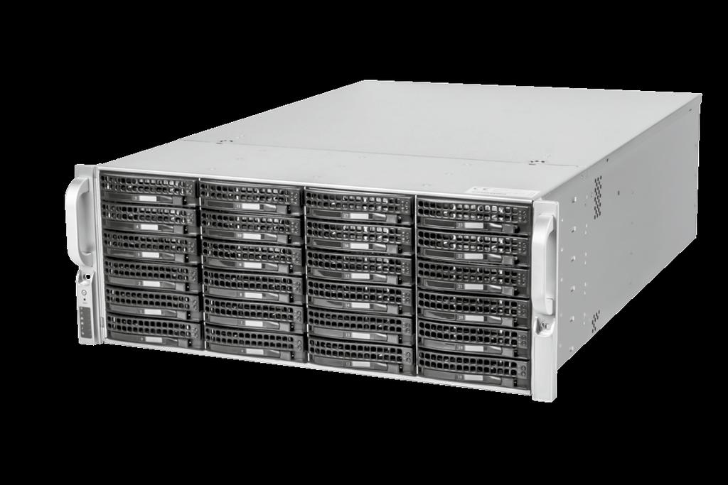
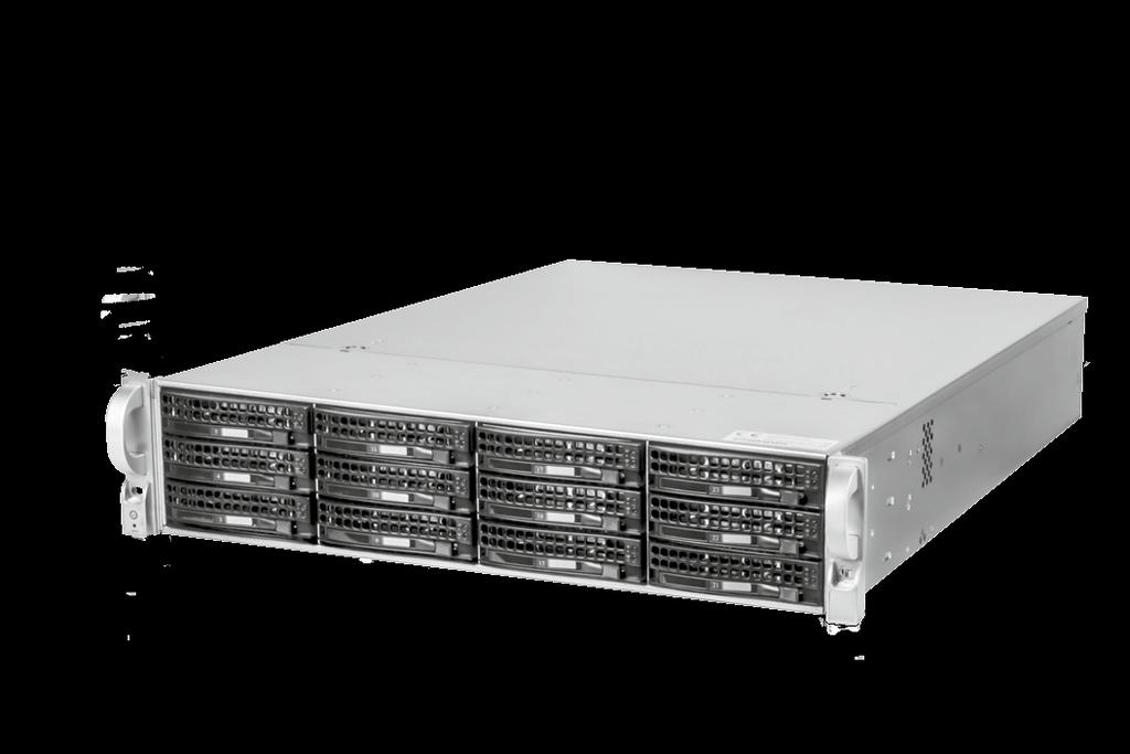
4 1 Validity This document applies to the following devices: SMAVIA Enterprise Storage JBOD - 12 SAS SMAVIA Enterprise Storage JBOD - 24 SAS SMAVIA Enterprise Storage JBOD - 45 SAS Figures in this document are based on the 12 SAS model, but may differ from the actual product. Corresponding descriptions are valid for the 24 SAS and 45 SAS model as well. 2 Documents The product documentation contains several documents which are included in the scope of delivery in a printed form and/or on a digital medium. Read all documents included in the scope of delivery carefully and thoroughly before using the device. Always follow the instructions, notes and warnings and observe the technical specifications in the product data sheet. Keep all documents in legible condition and in a suitable location for future reference. Regularly check the website for the latest updates on product documentation. 4
5 This Document Commissioning The document Commissioning (this document) contains detailed descriptions on installation, connection and commissioning of the device as well as safety instructions and general notes. The target audience of this document is trained system integrators. Other Applicable Documents Data Sheet The document Data Sheet contains detailed technical specifications, features and characteristics of the device. The target audience of the document is trained system integrators. 5
6 3 Typographical Conventions This document may contain various warning words and symbols that indicate potential sources of danger: DANGER DANGER indicates a hazardous situation which, if not avoided, will result in death or serious injury. WARNING WARNING indicates a hazardous situation which, if not avoided, could result in death or serious injury. CAUTION CAUTION indicates a hazardous situation which, if not avoided, could result in minor or moderate injury. NOTICE NOTICE is used to address practices not related to physical injury. 6
7 For reasons of clarity and readability, various text formatting elements and types of emphasis are used in this documentation: Instructions are indicated by arrows ( ). Always carry out instructions one after the other in the sequence described. Expressions in quotation marks generally indicate a control element on the device (switches or labels) or on its user interface (buttons, menu items). Paragraphs in italics provide information on basic principles, special features and efficient procedures as well as general recommendations. 7
8 4 Safety Instructions Only use the device if it is technically in proper working condition and for the intended purpose while keeping safety and potential dangers in mind. Qualified Personnel The installation, mounting, connection, commissioning and configuration of the device may only be carried out by qualified personnel. This also applies to the maintenance, testing and repair, whereat the regulations of the DIN VDE 0701 series of standards (repair, modification and inspection of electrical appliances) must be followed. Regulations The use of video and audio surveillance systems is, in general, strictly regulated. Inform yourself about the currently valid laws and regulations regarding data, worker and environmental protection before using the device and ensure compliance with them. System Components Only use internal components that have been tested and approved by Dallmeier. Inappropriate internal components may cause malfunctions, damages and data loss and may result in the loss of warranty. Modifications Do not make any modifications to the hardware or software that have not been tested and approved by Dallmeier. Inappropriate modifications may cause malfunctions, damages and data loss and may result in the loss of warranty. 8
9 Documentation Read the documents included in the delivery carefully and thoroughly. Always observe the contained instructions, notes and warnings. The product documentation contains several documents which are included in the scope of delivery in a printed form and/or on a digital medium. Keep all documents in legible condition and in a suitable location for future reference. Condensation Water If the device is brought from a cold to a warm environment, resulting condensation water may cause malfunctions and damages. In this case, wait (up to 8 hours) until the device has reached room temperature before commissioning. Earthing & Equipotential Bonding For the safety of persons (protection against dangerous contact voltages) and devices (protection against over-voltages) and the immunity of information and communication technology equipment to electromagnetic interferences (EMI), all protective measures, which are specified by the currently valid DIN, VDE and ISO standards and which provide for a standard-compliant earthing and a correct equipotential bonding of electrical and electronic devices, are mandatory and must be fulfilled by all means. Lightning Storms To avoid damage to the device by electrical surge during lightning storms, all protective measures, which are specified by the currently valid DIN, VDE and ISO standards and which provide for a standardcompliant lightning protection equipotential bonding, are mandatory and must be fulfilled by all means. 9
10 Operating Conditions Unfavorable operating conditions may shorten the life of the device and may cause malfunctions, damages and data loss and may result in the loss of warranty. Observe the specifications given in the technical data, the operating condition requirements and the maintenance instructions. Shocks Shocks may cause malfunctions and damages. The unit may not be moved while in operation. Foreign Bodies If objects or liquids get into the device, immediately disconnect it from the power supply (pull out the power plug). Contact the sales partner responsible for your area. Burnt Smell If you notice burnt smell or a formation of smoke coming from the device, immediately disconnect it from the power supply (pull out the power plug). Contact the sales partner responsible for your area. Opening The device may only be opened by qualified personnel for commissioning, inspection, maintenance and repair. Elevated ambient temperature The ambient temperature in a multi-unit rack may be higher than the room ambient. Ensure that the maximum ambient temperature in the rack complies with the requirements specified in the technical data. 10
11 Reduced air flow The air flow in a (closed) rack may be reduced. Ensure that the amount of air flow required for a safe operation is not compromised. Ensure sufficient ventilation with 4" (10 cm) of free space on the front, rear and right side of the device. Disposal Do not dispose waste electrical and electronic equipment into the household trash. Disconnect the device from the power supply. Remove all connected devices. Return the device to your respective sales partner. 11
12 5 General Notes Scope of Delivery The standard scope of delivery includes all brackets and screws that are necessary for a proper installation. The scope of delivery may differ depending on the ordered equipment, device variant or country of destination. The functional range of the device depends on the ordered equipment or device variant and may differ from this document s content. Certain functions and features may require the purchase of an additional license. Transportation and Packaging Store the original packaging for later transportation. Dallmeier is not responsible for any damage resulting from unprofessional/improper transportation. The device should only be shipped in the original packaging. If the original packaging is no longer available, ensure that the used packaging sufficiently protects the device against damage, moisture, heat and cold. Warranty The terms and conditions valid at time the contract was signed shall apply. Approvals/Certifications The following approvals/certifications were valid at the time of this document s compilation: CE Visit for possible updates. 12
13 Appropriate Use The product described in this document is a scalable JBOD system for the extension of a SMAVIA Enterprise Storage Server. It is available in three different sizes with up to 45 SAS hard disk drives. Each server can be extended with up to two JBOD systems. This allows the connection of up to 90 SAS hard disk drives with a total capacity of up to 540 TB. The SMAVIA Enterprise Storage JBODs are designed for installation in a 19" rack. The required mounting rails are included. Main Features Frames for SAS hard disk drives included SAS hard disk drives with 2000, 4000 or 6000 GB optional SAS cable SFF-8088 included Two highly efficient (80PLUS Platinum) and redundant power supply units Solid rack-mount housing Mounting rails for the installation in a 19" rack included 13
14 6 Requirements General Considerations The unit is designed for installation in a 19" rack. The required mounting rails are included. Unfavourable local conditions may shorten the life of the unit and may cause malfunctions or damages. Setup Location Leave at least 60 cm clearance in front of the rack to open the front door completely. Leave approximately 75 cm of clearance in the back of the rack to allow for sufficient airflow and access for servicing. Ensure a restricted access location, such as a dedicated equipment room or a service closet. Rack Precautions Ensure that the leveling jacks on the bottom of the rack are fully extended to the floor with the full weight of the rack resting on them. Ensure that stabilizers are attached to the rack in single rack installations. Ensure that racks are coupled together in multiple rack installations. Always make sure that the rack is stable before extending a component from the rack. Server Precautions Review the electrical and general safety precautions that came with the components you are adding to your chassis. Determine the placement of each component in the rack before you install the rails. Install the heaviest server components on the bottom of the rack first, and then work upward. 14
15 Use a regulating uninterruptible power supply (UPS) to protect the server from power surges, voltage spikes and to keep your system operating in case of a power failure. Allow the hot-swappable hard drives and power supply modules to cool before touching them. Always keep the rack s front door and all panels and components on the servers closed when not servicing to maintain proper cooling. 15
16 Rack Mounting Considerations Ambient Operating Temperature If installed in a closed or multi-unit rack assembly, the ambient operating temperature of the rack environment may be greater than the ambient temperature of the room. Therefore, consideration should be given to installing the equipment in an environment compatible with the manufacturer s maximum rated ambient temperature (TMRA). Sufficient Airflow Equipment should be mounted into a rack so that the amount of airflow required for safe operation is not compromised. Circuit Overloading Consideration should be given to the connection of the equipment to the power supply circuitry and the effect that any possible overloading of circuits might have on overcurrent protection and power supply wiring. Appropriate consideration of equipment nameplate ratings should be used when addressing this concern. Reliable Ground A reliable ground must be maintained at all times. To ensure this, the rack itself should be grounded. WARNING Danger of bodily injury To prevent bodily injury when mounting or servicing this unit in a rack, you must take special precautions to ensure that the system remains stable. 16
17 Power Supply The device is operated with 110/240 V AC, 50/60 Hz. NOTICE Prevention of separation from the circuit The plug of the supply line is used as disconnection device from the supply circuit. Use a socket-outlet that is installed near the unit. Ensure that the socket-outlet is easily accessible. Maintenance The housing of the unit may only be opened by qualified personnel for commissioning, inspection, maintenance and repair. WARNING Danger of electric stroke The device is equipped with two redundant power supply units. Ensure that both supply lines are disconnected from the supply circuit. CAUTION Danger of explosion if battery is incorrectly replaced Replace and discard the battery of the main board in accordance with the instructions of the manufacturer. 17
18 Cleaning If it is necessary to clean the device, observe the following notes: NOTICE Damage to the surface coating of the device Clean the housing with a soft, dry and antistatic cloth. Do not use detergents. 18
19 7 Connections and System Interface Mains Switch Reset LED Power Status LED Network Activity LAN 2 LED Power Fail LED Hard Disk Activity LED Network Activity LAN 1 LED Info Fig. 1 The chassis includes two push-buttons that control power to the system. Mains Switch The main power switch is used to apply or remove power from the power supply to the server system. Turning off system power with this button removes the main power but keeps standby power supplied to the system. Therefore, you must unplug system before servicing. Reset The reset button is used to reboot the system. 19
20 The server includes a control panel on the front that houses status monitoring lights. The externally accessible hard drives display status lights. The power supply displays status lights visible from the back of the chassis. LED Power Status Indicates power is being supplied to the system power supply units. This LED should normally be illuminated when the system is operating. LED Hard Disk Activity Indicates activity on the hard drive when flashing. LED Network Activity LAN 1/2 Indicates network activity on LAN 1/2 when flashing. LED Info Alerts operator of several states, as noted in the table below. Status Continuously on and red Blinking red (1 Hz) Blinking red (0.25 Hz) Solid blue Blinking blue Description An overheat condition has occurred. (This may be caused by cable congestion.) Fan failure, check for an inoperative fan. Power failure, check for a non-operational power supply. Local UID has been activated. Use this function to locate the server in a rack mount environment. Remote UID is on. Use this function to identify the server from a remote location. LED Power Fail Indicates a power supply has failed. 20
21 Overheating There are several possible responses if the system overheats. Use the LEDs to determine the nature of the overheating condition. Confirm that the chassis covers are installed properly. Check the routing of the cables and make sure all fans are present and operating normally. Verify that the heatsinks are installed properly. Drive Carrier LEDs The chassis includes externally accessible SAS/SATA drives. Each drive carrier displays two status LEDs on the front of the carrier. LED Color Green Red Description When illuminated, this LED indicates drive activity. It blinks on and off when that particular drive is being accessed. When illuminated, this LED indicates a drive failure. Power Supply LEDs On the rear of the power supply module, an LED displays the status. Status Solid Green Solid Amber Blinking Amber Description When illuminated, indicates that the power supply is on. When illuminated, indicates the power supply is plugged in and turned off, or the system is off but in an abnormal state. When blinking, this system power supply temperature has reached 63 C. The system will automatically power-down when the power supply temperature reaches 70 C and restart when the power supply temperature goes below 60 C. 21
22 8 Chassis Setup and Maintenance This chapter covers the steps required to install components and perform maintenance on the chassis. The only tool required is a Phillips screwdriver. NOTICE General risk of property damage and injury Review the warnings listed in the chapter Security Instructions. WARNING Danger of electric stroke The device is equipped with two redundant power supply units. Ensure that both supply lines are disconnected from the supply circuit Before performing some setup or maintenance tasks, use the following procedure to ensure that power has been removed from the system. Use the operating system to power down the unit. Pull the power cord out of the back of the power supply 1. Pull the power cord out of the back of the power supply 2. Disconnect the cord from the power strip or wall outlet. 22
23 Chassis Cover Proceed as described in order to remove the chassis cover. If necessary, unplug the chassis from any power source. Fig. 2 Remove the two screws securing the cover to the side of the chassis (2). Depress the two release buttons (3). Push the cover toward the rear (4). Lift the cover off the chassis (5). NOTICE Risk of damage Do not operate the server without the cover in place. The chassis cover must be in place to allow proper airflow and prevent overheating. 23
24 Hard Disk Drives The drives are mounted in drive carriers to simplify their installation and removal from the chassis. These carriers also help to promote proper airflow for the drive bays. Proceed as described in order to remove a drive carrier, remove the dummy drive and mount the drive in the carrier. Fig. 3 Press the release button to extend the drive carrier handle (1). Use the handle to pull the drive carrier out of the chassis (2). Except for short periods of time, such as while swapping hard drives, do not operate the server with the carriers removed from the chassis drive bays. 24
25 Fig. 4 Remove the two screws securing the dummy (3). Remove the dummy drive. Fig. 5 Slide the drive into the carrier with the circuit board side facing down. Align the mounting holes in both the drive carrier and the drive. Secure the hard drive to the carrier using six screws (4). Replace the drive carrier into the chassis and close/lock the handle. 25
26 Air Shroud Air shrouds concentrate airflow to maximize fan effectiveness. It does not require screws for its installation. Proceed as described in order to install the air shroud. It is designed with removable break-away tabs that allow the air shroud to be adjusted to fit a variety of boards. Fig. 6 The air shroud fits behind the fans and beside to the power supply. Move any cables that interfere with the air shroud placement. Place the air shroud in the chassis. Remove any break-away tabs necessary to ensure a proper fit with the board. 26
27 System Fan The chassis is equipped with three hot-swappable fans for cooling from the middle, augmented by two rear exhaust fans. Proceed as described in order to replace a system fan. Fig. 7 Remove the failed fan s power cord from the board. Press the fan release tab and pull it out of the chassis. Fig. 8 Place the new fan into the vacant space. Ensure that the arrows on the top of the fan (indicating airflow direction) point in the same direction as the arrows on the other fans. 27
28 Power Supply The chassis has a redundant power supply. Redundant power supplies are hot-swappable, and can be changed without powering down the system. This power supply is auto-switching capable. This enables it to automatically sense and operate at a 100 V to 240 V input voltage. An amber light will be illuminated on the power supply when the power is off. An illuminated green light indicates that the power supply is operating. Proceed as described in order to replace a power supply module. Fig. 9 Unplug the AC cord from the power supply module to be replaced. Push the release tab on the back of the power supply module. Pull the power supply module out of the chassis using the handle provided. 28
29 Replace the failed power supply module with the same model. Push the new power supply module into the power bay until it locks. Plug the AC power cord back into the module. 29
30 9 Rack Installation This chapter provides information on installing the server into a rack with the rails provided. There are a variety of racks on the market, so the assembly procedure may differ slightly. Refer to the installation instructions that came with your rack. The provided rails fit a rack between 67 cm and 92 cm deep. Identifying the Rack Rail The chassis package includes two rail assemblies, one designed and labeled for each side of the chassis. Each assembly consists of an inner rail that secures directly to the chassis, and an outer rail that secures to the rack. The outer rail has two sections that can slide and adjust to fit your rack depth. Fig
31 Releasing the Inner Rail Each inner rail has a locking latch. This latch prevents the server from coming completely out of the rack when the chassis is pulled out for servicing. Proceed as described in order to release the inner rail from the outer rails. Fig. 11 Pull the inner rail out of the outer rail until it is fully extended (1). Press the locking tab down to release the inner rail (2). Pull the inner rail all the way out (3). 31
32 Installing the Inner Rails Proceed as described in order to install the inner rails on the chassis. Fig. 12 Identify the left and right inner rails. They are labeled. Place the inner rail firmly against the side of the chassis (2). Align the hooks on the side of the chassis with the holes in the inner rail (2). Slide the inner rail forward toward the front of the chassis until the quick release bracket snaps into place, securing the rail to the chassis (3). Secure the inner rail to the chassis with screws (4). 32
33 Installing the Outer Rails Proceed as described in order to install the outer rails on the rack. Fig. 13 Press upward on the locking tab at the rear end of the middle rail (1). Push the middle rail back into the outer rail (2). Hang the hooks on the front of the outer rail onto the square holes on the front of the rack (3). Use screws to secure the outer rails to the rack (3). Pull out the rear of the outer rail, adjusting the length until it just fits within the posts of the rack (4). Hang the hooks of the rear section of the outer rail onto the square holes on the rear of the rack. Take care that the proper holes are used so the rails are level. Use screws to secure the rear of the outer rail to the rear of the rack. 33
34 Sliding the Chassis onto the Rack Rails Proceed as described in order to slide the chassis onto the installed rack rails. WARNING Danger of bodily injury and damage Mounting the system into the rack requires at least two people to support the chassis during installation. Follow safety recommendations printed on the rails. NOTICE Risk of damage The handles of the chassis are designed to pull the system from a rack. Do not pick up the chassis with the front handles. 34
35 Fig. 14 Align the inner rails of the chassis with the outer rails on the rack. Slide the inner rails into the outer rails. While sliding, keep the pressure even on both sides. Ensure to slide the chassis completely until it clicks into the locked position. Use screws to secure the front of the chassis to the rack. The figure above is for illustrative purposes only. Always install servers to the bottom of the rack first. WARNING Danger of bodily injury and damage The rack stabilizing mechanism must be in place, or the rack must be bolted to the floor before you slide the unit out for servicing. Ensure a stabilized rack to prevent it from tipping over. 35
36 Dallmeier electronic GmbH & Co.KG Cranachweg Regensburg Germany Phone +49 (0) Fax +49 (0) info@dallmeier.com
Quick Guide. English. Appliance. SMAVIA Enterprise JBOD. Rev /
 Quick Guide English Appliance IPS 10 000 SMAVIA Enterprise JBOD Rev. 1.0.0 / 2017-02-13 Information about copyright, trademarks, design patents 2017 Dallmeier electronic The reproduction, distribution
PTZ Control VMC Joystick
 Installation and Configuration English PTZ Control VMC Joystick Rev. 1.0.0 / 2010-07-20 Information about Copyright, Trademarks, Design Patents 2010 Dallmeier electronic The reproduction, distribution
Workstation Rack Commissioning
 Workstation Rack Commissioning English 005522 / 1.0.0 / 2015-04-23 Information about Copyright, Trademarks, Design Patents 2015 Dallmeier electronic The reproduction, distribution and utilization of this
DIS-2/M UTP DIS-2/M NSU DIS-2/M Multi-D HD
 Commissioning English Dallmeier DIS-2/M UTP DIS-2/M NSU DIS-2/M Multi-D HD 004076 / 1.0.0 / 2012-10-30 Content Content Validity...2 Conventions...2 Environmental Conditions...2 Safety Instructions...3
Video Management Center VMC-1
 Installation and Configuration English Video Management Center VMC-1 Rev. 1.1.0 / 2010-07-20 Information about Copyright, Trademarks, Design Patents 2010 Dallmeier electronic The reproduction, distribution
Obtaining Documentation and Submitting a Service Request, page xvii Safety Warnings, page xvii Safety Guidelines, page xx
 Preface Obtaining Documentation and Submitting a Service Request, page xvii Safety s, page xvii Safety Guidelines, page xx Obtaining Documentation and Submitting a Service Request For information on obtaining
2U Server. User Manual
 2U Server User Manual The information in this User Manual has been carefully reviewed and is believed to be accurate. The vendor assumes no responsibility for any inaccuracies that may be contained in
350 East Plumeria Drive San Jose, CA USA February
 Installation Guide 350 East Plumeria Drive San Jose, CA 95134 USA February 2013 201-15135-03 Support Thank you for selecting NETGEAR products. After installing your device, locate the serial number on
DIS-2/M DecoderPro HD
 Configuration English Audio and Video Decoder DIS-2/M DecoderPro HD Rev. 1.0.1 / 2012-10-26 Information about Copyright, Trademarks, Design Patents 2012 Dallmeier electronic The reproduction, distribution
350 East Plumeria Drive San Jose, CA USA May
 Installation Guide 350 East Plumeria Drive San Jose, CA 95134 USA May 2012 201-15135-02 NETGEAR, Inc. All rights reserved. No part of this publication may be reproduced, transmitted, transcribed, stored
MDF4220HD Commissioning
 MDF4220HD English 004709 / 2.0.0 / 2017-01-17 MDF4220HD Information about Copyright, Trademarks, Design Patents 2017 Dallmeier electronic The reproduction, distribution and utilization of this document
DMS / DLS / VNS Recorders
 Commissioning English Dallmeier DMS / DLS / VNS Recorders 00077 / Rev...0 Contents Contents Validity...2 Safety instructions...3 Requirements...4 HDD mounting...5 Mounting DMS... 6 Mounting DLS / VNS...7
JanusRAID SA-6692J Hardware User Manual
 JanusRAID SA-6692J Hardware User Manual 42-30000-5067 SATA II JBOD enclosure Version 1.1 SA-6692J SATA II JBOD enclosure Hardware User Manual Table of Contents Preface... i Chapter 1 System Requirements
Lightspeed Advanced Reporting Bottle Rocket Hardware Installation Guide
 Lightspeed Advanced Reporting Bottle Rocket Hardware Installation Guide 1800 19th Street / Bakersfield, CA 93301 / Tel: 661.716.7600 / Toll Free: 877.447.6244 / www.lightspeedsystems.com Table of Contents
Dell MD1280 Storage Enclosure Getting Started Guide
 Dell MD1280 Storage Enclosure Getting Started Guide Regulatory Model: SP-2584, E11J Notes, Cautions, and Warnings NOTE: A NOTE indicates important information that helps you make better use of your computer.
Preparing to Install the VG248
 CHAPTER 2 To ensure normal system operation, plan your site configuration and prepare your site before installation. Before installing the VG248, review these sections: Preparing the Installation Site,
LVN5200A-R2, rev. 1, Hardware Installation Guide
 LVN5200A-R2 LVN5250A-R2 LVN5200A-R2, rev. 1, Hardware Installation Guide Customer Support Information Order toll-free in the U.S.: Call 877-877-BBOX (outside U.S. call 724-746-5500) FREE technical support
Network Camera. Quick Guide DC-B1203X. Powered by
 Network Camera Quick Guide DC-B1203X Powered by Safety Precautions English WARNING RISK OF ELECTRIC SHOCK DO NOT OPEN WARNING: TO REDUCE THE RISK OF ELECTRIC SHOCK, DO NOT REMOVE COVER (OR BACK). NO USER-SERVICEABLE
Cisco CRS 3-Phase AC Power Distribution Unit Installation Guide 2. Cisco CRS 3-Phase AC Power Distribution Unit 2
 Cisco CRS 3-Phase AC Power Distribution Unit Installation Guide Cisco CRS 3-Phase AC Power Distribution Unit Installation Guide 2 Cisco CRS 3-Phase AC Power Distribution Unit 2 Revised: November 18, 2016,
Installation and Configuration. English. Workstation PVS 7. Rev /
 Installation and Configuration English Workstation PVS 7 Rev. 2.1.0 / 100426 Information about copyright, trademarks, design patents 2010 Dallmeier electronic The reproduction, distribution and utilization
16Hi HARDWARE INSTALLATION GUIDE
 16Hi HRDWRE INSTLLTION GUIDE Table of Contents Section 1 Ratings....................................................................... 3 Section 2 Site Preparation................................................................
HP UPS R/T3000 ERM. Overview. Precautions. Installation Instructions
 HP UPS R/T3000 ERM Installation Instructions Overview The ERM consists of two battery packs in a 2U chassis. The ERM connects directly to a UPS R/T3000 or to another ERM. Up to two ERM units can be connected.
Serial ATA Hot Swap Drive Cage Upgrade Kit for: Intel Server Chassis SC5200 Intel Server Chassis SC5250-E
 Serial ATA Hot Swap Drive Cage Upgrade Kit for: Intel Server Chassis SC5200 Intel Server Chassis SC5250-E A Guide for Technically Qualified Assemblers of Intel Identified Subassemblies/Products Order Number:
easyraid Q24P2-U4R4 Hardware Manual
 easyraid Q24P2-U4R4 Hardware Manual 42-30000-5105 SCSI Channel to Serial ATA II Disk Array System Version 1.0 easyraid Q24P2-U4R4 U320 SCSI Channel to Serial ATA II Disk Array System Hardware User Manual
Table of Contents Quick Install Guide page Introduction Safety Rack System Precautions ESD Precautions...
 Table of Contents Quick Install Guide page 1 EN English Table of Contents 1. Introduction... 2 1.1 Safety... 2 1.2 Rack System Precautions... 2-3 1.3 ESD Precautions... 3... 3 1... 3 2 Fitting PSU s...
Operation. English. Recording Server. WebConfig. Rev /
 Operation English Recording Server WebConfig Rev. 1.0.0 / 2014-11-27 Information about copyright, trademarks, design patents 2014 Dallmeier electronic The reproduction, distribution and utilization of
D610H, D610H MKII, D610S, D610T dimmer pack. user manual
 D610H, D610H MKII, D610S, D610T dimmer pack user manual Musikhaus Thomann Thomann GmbH Hans-Thomann-Straße 1 96138 Burgebrach Germany Telephone: +49 (0) 9546 9223-0 E-mail: info@thomann.de Internet: www.thomann.de
Remote Configuration Software DMS NetConfig 2
 Installation and Operation English Remote Configuration Software DMS NetConfig 2 Rev. 1.0.0/ 2010-07-22 Information about copyright, trademarks, design patents 2010 Dallmeier electronic The reproduction,
SATA II HDD Canister KISS DA 435 Quick Reference Guide
 SATA II HDD Canister KISS DA 435 Quick Reference Guide If it s embedded, it s Kontron 1. Table of Contents SATA II HDD Canister KISS DA 435 1. Table of Contents 1. Table of Contents... 1 2. Important Information...
3-Phase, Dual-Input 6-Slot Power Supply System STARTUP GUIDE
 3-Phase, Dual-Input 6-Slot Power Supply System STARTUP GUIDE -ST-01 Page 1 of 10 November 2016 2016 Copyright Lite-On Technology Corporation ALL RIGHTS RESERVED. Lite-On is a trademark of Lite-On Technology
InnoMedia Business VoIP ATA Models
 InnoMedia Business VoIP ATA Models MTA8328-4, MTA8328-8, MTA8328-24 Quick Installation Guide Important Safety Instructions Protective Earthing Protective earthing is used as a safeguard. This equipment
Replacing the RAID Battery Backup Unit Assembly on Series 3 FireSIGHT 3500 Defense Centers, Version 5.x
 Replacing the RAID Battery Backup Unit Assembly on Series 3 FireSIGHT 3500 Defense Centers, Version 5.x Last Updated: December 4, 2014 Use these instructions to replace the RAID battery backup unit (BBU)
One Identity Safeguard 2.1. Appliance Setup Guide
 One Identity Safeguard 2.1 Appliance Setup Guide Copyright 2017 One Identity LLC. ALL RIGHTS RESERVED. This guide contains proprietary information protected by copyright. The software described in this
Video Management System SeMSy III Workstation Software
 Installation English Video Management System SeMSy III Workstation Software Rev. 1.1.0 / 2016-09-14 Information about Copyright, Trademarks, Design Patents 2016 Dallmeier electronic The reproduction, distribution
Omnitron Systems Technology, Inc. 1. iconverter. 19-Module Managed Power Chassis User s Manual
 Omnitron Systems Technology, Inc. 1 iconverter 19-Module Managed Power Chassis User s Manual 27 Mauchly, #201, Irvine, CA 92618 Phone: (949) 250-6510; Fax: (949) 250-6514 2 Omnitron Systems Technology,
LifeSize ClearSea Installation Guide August 2012
 LifeSize ClearSea Installation Guide August 2012 LifeSize ClearSea LifeSize ClearSea Virtual Machine LifeSize ClearSea Installation Guide 2 LifeSize ClearSea This guide describes how to install and configure
64 Bays SAS to SAS/SATA JBOD Subsystem. User Manual. Revision 1.0
 64 Bays SAS to SAS/SATA JBOD Subsystem Revision 1.0 Table of Contents Preface... 4 Before You Begin... 5 Safety Guidelines... 5 Controller Configurations... 5 Packaging, Shipment and Delivery... 5 Unpacking
Video Management System SeMSy III Setup Server
 Installation English Video Management System SeMSy III Setup Server Rev. 1.0.0 / 2012-12-20 Information about Copyright, Trademarks, Design Patents 2012 Dallmeier electronic The reproduction, distribution
Configuration. English. Video Management System. SeMSy III Modul Map. Rev /
 Configuration English Video Management System SeMSy III Modul Map Rev. 1.0.1 / 2014-08-31 Information about Copyright, Trademarks, Design Patents 2014 Dallmeier electronic The reproduction, distribution
Emerson Network Power provides customers with technical support. Users may contact the nearest Emerson local sales office or service center.
 Liebert PSA iton User Manual Version: V2.8 Revision date: November 14, 2005 Emerson Network Power provides customers with technical support. Users may contact the nearest Emerson local sales office or
DC-V3213XJ-4.3mm DC-V3213XJ-2.5mm
 Network Camera Quick Guide DC-V3213XJ-4.3mm DC-V3213XJ-2.5mm Powered by Safety Precautions WARNING RISK OF ELECTRIC SHOCK DO NOT OPEN WARNING: TO REDUCE THE RISK OF ELECTRIC SHOCK, DO NOT REMOVE COVER
Installing and Configuring Rialto Analytic Appliances
 Installing and Configuring Rialto Analytic Appliances Important Safety Information This manual provides installation and operation information and precautions for the use of this camera. Incorrect installation
ReadyNAS OS 6 Rack-Mount Hardware Manual
 Rack-Mount Hardware Manual Model ReadyNAS 2120 ReadyNAS 2120 v2 ReadyNAS 3130 ReadyNAS 3138 ReadyNAS 3220 ReadyNAS 3312 ReadyNAS 4220 ReadyNAS 4312 ReadyNAS 4360 April 2017 202-11272-08 350 E. Plumeria
SeMSy III Interface Server / Clients
 Installation English Video Management System SeMSy III Interface Server / Clients Rev. 2.0.1 / 2015-10-09 Information about Copyright, Trademarks, Design Patents 2015 Dallmeier electronic The reproduction,
3-4 SAS/SATA II HDD Canister Entry version USER S MANUAL XC-34D1-SA10-0-R. Document number: MAN A
 3-4 SAS/SATA II HDD Canister Entry version XC-34D1-SA10-0-R USER S MANUAL Document number: MAN-00077-A ii Preface Important Information Warranty Our product is warranted against defects in materials and
SeMSy III Interface Server / Clients
 Installation English Video Management System SeMSy III Interface Server / Clients Rev. 2.0.3 / 2017-01-13 Information about Copyright, Trademarks, Design Patents 2017 Dallmeier electronic The reproduction,
Allworx 24x Service and Troubleshooting Guide
 Allworx 24x Service and Troubleshooting Guide -PAGE INTENTIALLY LEFT BLANK- Table of Contents 1 Safety Instructions...1 1.1 Electrical...1 1.2 Electrostatic Discharge...1 2 Chassis Views...2 3 Exterior
DS-1H05 Ethernet-over-Coax Extender. User Manual
 DS-1H05 Ethernet-over-Coax Extender User Manual Thank you for purchasing our product. If there is any question or request, please do not hesitate to contact dealer. This manual is applicable to DS-1H05-T,
Unified Office Gateway UMG Quick Installation Guide. Version: 1.0
 Unified ice Gateway UMG-2000 Quick Installation Guide Version: 1.0 Table of Contents 1. Package Contents... 3 2. Overview... 4 3. Hardware Installation... 6 3.1 Unpack the UMG-2000... 6 3.2 Choosing a
Operating and Installation Manual. EASYLAB Expansion modules Type EM-TRF for 230 V AC mains voltage
 Operating and Installation Manual EASYLAB Expansion modules Type EM-TRF for 230 V AC mains voltage Type EM-TRF-USV for 230 V AC mains voltage; provides uninterruptible power supply (UPS) The art of handling
CPCI System Subrack 1 U
 User s Manual Product No.: Doc-No: 63972-165_R1.0 January 14, 2008 Rev. Date updated Change R1.0 January 14, 2008 Initial Release Impressum: Schroff GmbH D-75334 Straubenhardt, Germany The details in this
English. Installation and Operation. PTZ Controller WTX Rev /
 English Installation and Operation PTZ Controller WTX-2000 Rev. 1.0.1 / 070123 PTZ Controller - WTX-2000 Copyright All rights reserved. This document may not be copied, photocopied, reproduced, translated,
QUICKSTART INSTALLATION INSTRUCTIONS
 WEGENER i8640 DIGITAL AUDIO SERVER QUICKSTART INSTALLATION INSTRUCTIONS This satellite receiver has been provided for the reception of MRN, WestwoodOne or Compass Sports. Once installed, please contact
D1210H dimmer pack. user manual
 D1210H dimmer pack user manual Musikhaus Thomann Thomann GmbH Hans-Thomann-Straße 1 96138 Burgebrach Germany Telephone: +49 (0) 9546 9223-0 E-mail: info@thomann.de Internet: www.thomann.de 13.08.2015,
Thank you for selecting UTC RETAIL s innovative Model 1170 Point of Sale solution!
 1170 POS SYSTEM 1170 INSTALLATION GUIDE Thank you for selecting UTC RETAIL s innovative Model 1170 Point of Sale solution! This Installation Guide will help you efficiently install the 1170 POS. The document
Installation of the POTS splitter card requires the following steps: Determining the cables you need. Installing the POTS splitter chassis
 5910 High Density Lifeline POTS Splitter Installation Instructions Document Number 5910-A2-GZ40-00 May 2005 About the 5910 POTS Splitter The 5910 is a double-density POTS splitter that separates the (Digital
Configuration and Operation. English. DMVC App. Client Software for Dallmeier Recording Systems and DMVC Server
 Configuration and Operation English Client Software for Dallmeier Recording Systems and DMVC Server Rev. 2.0.0 /12-09-2017 Information about Copyright, Trademarks, Design Patents 2017 Dallmeier electronic
Installation Job Aid for VSP 4850GTS
 Installation Job Aid for VSP 4850GTS Notices Release 6.1.0.0 NN46251-308 Issue 02.01 November 2017 Notice paragraphs alert you about issues that require your attention. The following paragraphs describe
The power behind competitiveness. Delta Infrasuite Power Management. Power Distribution Unit. User Manual.
 The power behind competitiveness Delta Infrasuite Power Management Power Distribution Unit User Manual www.deltapowersolutions.com Save This Manual This manual contains important instructions and warnings
HP UPS R/T3000 G2. Overview. Precautions. Kit contents. Installation Instructions
 HP UPS R/T3000 G2 Installation Instructions Overview The HP UPS R/T3000 G2 features a 2U rack-mount with convertible tower design and offers power protection for loads up to a maximum of 3300 VA/3000 W
G3-APEX-ENT-32T. Apex technical specifications. Parts list
 Apex Enterprise Hardware Installation 25 May 2018 G3APEXENT32T The G3APEXENT32T is best suited for any data center. Apex technical specifications System Deployment Base storage 32 TB Max storage 32 TB
Manual Version: V1.00. Video Decoder Quick Guide
 Manual Version: V1.00 Video Decoder Quick Guide Thank you for purchasing our product. If there are any questions, or requests, please do not hesitate to contact the dealer. Copyright Copyright 2016 Zhejiang
Operation. English. Detection And Evaluation Of Licence Numbers. SEDOR ANPR Server. Rev /
 Operation English Detection And Evaluation Of Licence Numbers SEDOR ANPR Server Rev. 1.0.0 / 2015-03-25 Information about copyright, trademarks, design patents 2015 Dallmeier electronic The reproduction,
User s Guide. for egfx Breakaway Box and egfx Breakaway Box 550 Thunderbolt 3 to egpu PCIe Card Expansion Systems
 User s Guide for egfx Breakaway Box and egfx Breakaway Box 550 Thunderbolt 3 to egpu PCIe Card Expansion Systems Important GPU Card Compatibility and Installation Information For users installing a GPU
Arcserve UDP 8100 and UDP 8200
 HARDWARE INSTALLATION GUIDE Arcserve UDP 8100 and UDP 8200 Appliance Hardware Installation Guide Table of Contents Section 1 Safety Notice and Warnings........................................... 3 Section
Main Functions. English. Viewing Client
 Main Functions English Viewing Client Rev. 2.0.0/ 2015-12-9 004057 / Rev. 1.0.0 / 2012-08-10 Validity...2 Safety Instruction...2 Documents...2 Typographical Conventions...2 Login...3 Activation...4 Zoom...6
Customer Replacement Procedure
 Customer Replacement Dell EMC Unity Family Dell EMC Unity All Flash and Unity Hybrid Replacing a faulted 80-drive DAE cooling module 302-003-777 REV 01 July 2017 This document describes how to replace
To connect the AC adapter:
 Replacing the AC Adapter Replacing the AC Adapter 3 Plug the power cord into a wall outlet. The power indicator turns on. To connect the AC adapter: Connect the power cord to the AC adapter. Power indicator
icore Kiosk system Installation Guide
 icore Kiosk system Installation Guide The reproduction, transmission or use of this document or its contents is not permitted without express authority. Offenders will be liable for damages. All rights,
TVAC25100 TVAC25110 User manual
 TVAC25100 TVAC25110 User manual Version 11/2010 Original user manual. Keep for future use. 12 Introduction Dear Customer, Thank you for purchasing this product. This product meets the requirements of the
Dell Networking S4100-ON Series. Set-Up Guide
 Dell Networking S4100-ON Series Set-Up Guide Notes, cautions, and warnings NOTE: A NOTE indicates important information that helps you make better use of your product. CAUTION: A CAUTION indicates either
Dell Networking S4810 Open Networking (ON) Getting Started Guide
 Getting Started Guide") Dell Networking S4810 Open Networking (ON) Getting Started Guide Regulatory Model: S4810 Notes, Cautions, and Warnings NOTE: A NOTE indicates important information that helps you make better use of your
Dell Networking S4810 Open Networking (ON) Getting Started Guide Regulatory Model: S4810 Notes, Cautions, and Warnings NOTE: A NOTE indicates important information that helps you make better use of your
1 Channel Strobe Controller ORDERCODE 40226
 1 Channel Strobe Controller ORDERCODE 40226 Congratulations! You have bought a great, innovative product from Showtec. The Showtec Strobe Controller brings excitement to any venue. Whether you want simple
Installing and Managing the Switch
 CHAPTER 2 This chapter describes how to install and manage the Cisco SFS 7008 system hardware and contains these sections: Safety, page 2-2 Preparing the Site, page 2-3 Rack-Mounting the Switch, page 2-4
DC-D4213RX DC-D4213WRX
 Network Camera Quick Guide DC-D4213RX DC-D4213WRX Powered by Safety Precautions WARNING RISK OF ELECTRIC SHOCK DO NOT OPEN WARNING: TO REDUCE THE RISK OF ELECTRIC SHOCK, DO NOT REMOVE COVER (OR BACK).
Replacing the Power Supply
 APPENDIX B This appendix includes information on how to replace the power supply for the Cisco AS550XM universal gateway and contains the following sections: Safety Recommendations, page B-1 Required Tools
Operation. English. Viewer. Rev /
 Operation English Viewer Rev. 2.0.0 / 2017-11-13 Information about Copyright, Trademarks, Design Patents 2017 Dallmeier electronic The reproduction, distribution and utilization of this document as well
Network Camera. Quick Guide DC-D1223WX. Powered by
 Network Camera Quick Guide DC-D1223WX Powered by Safety Precautions WARNING RISK OF ELECTRIC SHOCK DO NOT OPEN WARNING: TO REDUCE THE RISK OF ELECTRIC SHOCK, DO NOT REMOVE COVER (OR BACK). NO USER-SERVICEABLE
Sivy SA-4327S Hardware User Manual
 Sivy SA-4327S Hardware User Manual esata to Serial ATA II Disk Array System Version 1.0 SA-4327S esata to Serial ATA II Disk Array System Hardware User Manual Table of Contents Preface... i Chapter 1
Documentation KM2042. Sixteen channel digital output module with D-Sub Connector. Version: Date:
 Documentation Sixteen channel digital output module with D-Sub Connector Version: Date: 2.0.0 2017-11-20 Table of contents Table of contents 1 Foreword... 5 1.1 Notes on the documentation... 5 1.2 Safety
B&W RearView Camera Installation & Operation
 B&W RearView Camera Installation & Operation CA52 (Camera) FOR MORE INFORMATION WWW.STRATEGICVISTA.COM BEFORE OPERATING THIS SYSTEM, PLEASE READ THIS MANUAL THOROUGHLY AND RETAIN IT FOR FUTURE REFERENCE
Rack Installation Instructions
 Rack Installation Instructions For System Storage EXP2512 and EXP2524 Express Storage Enclosures Use the instructions in this document to install an IBM System Storage EXP2512 Express Storage Enclosure
LED Pixel Rail Drive 640 controller. user manual
 LED Pixel Rail Drive 640 controller user manual Musikhaus Thomann Thomann GmbH Hans-Thomann-Straße 1 96138 Burgebrach Germany Telephone: +49 (0) 9546 9223-0 E-mail: info@thomann.de Internet: www.thomann.de
Installation- and Operating instructions for CU Ethernet Controller with USB Input. Version: 1.4 Date:
 Installation- and Operating instructions for CU8880-0010 Ethernet Controller with USB Input Version: 1.4 Date: 2018-04-12 Table of contents Table of contents 1. 2. 3. 4. 5. General instructions 2 Notes
User Manual AIMB-C200. Economical Embedded Chassis for Mini-ITX Motherboard
 User Manual AIMB-C200 Economical Embedded Chassis for Mini-ITX Motherboard Copyright The documentation and the software included with this product are copyrighted 2010 by Advantech Co., Ltd. All rights
HX1 Bluetooth Stereo Headset
 HX1 Bluetooth Stereo Headset Ref. nr.: 130.115 INSTRUCTION MANUAL V1.1 ENGLISH Congratulations to the purchase of this Max product. Please read this manual thoroughly prior to using the product in order
Junos WebApp Secure 5.0 Hardware Guide
 Junos WebApp Secure 5.0 Hardware Guide Junos WebApp Secure 5.0 Hardware Guide This document contains a specification for the MWS1000 hardware appliance, as well as instructions for installation into a
Installing the Cisco MDS 9020 Fabric Switch
 CHAPTER 2 This chapter describes how to install the Cisco MDS 9020 Fabric Switch and its components, and it includes the following information: Pre-Installation, page 2-2 Installing the Switch in a Cabinet
Tiger Box Expansion Chassis Assembly Guide
 Tiger Box Expansion Chassis Assembly Guide Product Overview................................. 3 Tiger Box Expansion Chassis Features............... 3 Package Content............................. 4 Hardware
CX1 Outdoor Color-Changing Wireless Bluetooth Speaker Please fully charge the speaker prior to first use!
 CX1 Outdoor Color-Changing Wireless Bluetooth Speaker 130.109 Please fully charge the speaker prior to first use! 1 ENGLISH Congratulations to the purchase of this Max product. Please read this manual
System Storage EXP3000 Rack Installation Instructions
 System Storage EXP3000 Rack Installation Instructions Review the documentation that comes with your rack cabinet for safety and cabling information. When you install the IBM System Storage EXP3000 in a
DPX-620III 6-Ch. dimmer pack. user manual
 DPX-620III 6-Ch. dimmer pack user manual Musikhaus Thomann Thomann GmbH Hans-Thomann-Straße 1 96138 Burgebrach Germany Telephone: +49 (0) 9546 9223-0 E-mail: info@thomann.de Internet: www.thomann.de 28.08.2017,
Installation Job Aid for VSP 4450GTX-HT- PWR+
 Installation Job Aid for VSP 4450GTX-HT- PWR+ Notices Release 6.1.0.0 NN46251-305 Issue 02.01 November 2017 Notice paragraphs alert you about issues that require your attention. The following paragraphs
UP-1-1 Channel Dimmer dimmer pack. user manual
 UP-1-1 Channel Dimmer dimmer pack user manual Musikhaus Thomann Thomann GmbH Hans-Thomann-Straße 1 96138 Burgebrach Germany Telephone: +49 (0) 9546 9223-0 E-mail: info@thomann.de Internet: www.thomann.de
User s Manual (Model A) isappos 9/12 Stand
 isappos 9/12 Stand") User s Manual (Model A) isappos 9/12 Stand Section 1 Overview The Jacket (unit: mm) Package Contents Aluminum base plate Aluminum Stand body Jacket for ipad 1 x Micro-USB cable (For charging and data syncing)
User s Manual (Model A) isappos 9/12 Stand Section 1 Overview The Jacket (unit: mm) Package Contents Aluminum base plate Aluminum Stand body Jacket for ipad 1 x Micro-USB cable (For charging and data syncing)
Network Camera. Quick Guide DC-T3243HRX. Powered by
 Network Camera Quick Guide DC-T3243HRX Powered by Safety Precautions WARNING RISK OF ELECTRIC SHOCK DO NOT OPEN WARNING: TO REDUCE THE RISK OF ELECTRIC SHOCK, DO NOT REMOVE COVER (OR BACK). NO USER-SERVICEABLE
DC-D2212R / DC-D2212WR
 Network Camera Quick Guide / DC-D2212WR Powered by Safety Precautions WARNING RISK OF ELECTRIC SHOCK DO NOT OPEN WARNING: TO REDUCE THE RISK OF ELECTRIC SHOCK, DO NOT REMOVE COVER (OR BACK). NO USER-SERVICEABLE
HP R/T2200 UPS. Overview. Precautions. Installation Instructions. The HP UPS R/T2200 features power protection for loads up to 2200 VA/1600 W.
 HP R/T2200 UPS Installation Instructions Overview The HP UPS R/T2200 features power protection for loads up to 2200 VA/1600 W. For more information about any of the topics covered in this document, see
Operating Instructions
 TPS S1 AC in DC out Translation of the original instructions TPS 110-400 Mains pack Operating Instructions PT 0199 BEN/C (1010) EN Table of contents Table of contents 1 About this manual...............................................
Installing the Cisco SFS 3504 Server Switch
 CHAPTER 3 This chapter describes how to mount your Cisco SFS 3504 Server Switch on a rack, boot the Cisco SFS 3504 Server Switch, and configure basic services. For advanced configuration information, see