FutureLink Modular. Fiber Optic Cabling System. Issue 1. Corning Cable Systems. Project Services. Data Centers OEM. Private Networks.
|
|
|
- Tyler Hoover
- 6 years ago
- Views:
Transcription


1 FutureLink Modular Fiber Optic Cabling System Issue 1 Corning Cable Systems Vogel. Michael P. Giordano. November 2000 Carrier Networks Private Networks OEM Data Centers Project Services
2 Introduction 6 Corning: An Experienced and Reliable Partner for You 7 The Customer is Our Focal Point 8 Corning Cable Systems: Global Cable and Hardware Business 10 Standards for Structured Premises Cabling Solutions 11 Structured Cabling to ISO/IEC (2000) and EN (2000) 15 Future Standards for Structured Premises Cabling Solutions 16 Planned Additions for the Future Editions of EN (2002) and ISO/IEC (2002) 18 Laser-Optimized Multimode Fibers for Gigabit Ethernet 20 Laser-Optimized InFiniCor Fibers System description 22 FutureLink Modular System Description Cables 26 Cables 28 FutureLink Modular Cables Technical Data MPC (Multi-Purpose Cables) 30 MPC, Loose Tube Designs 36 MPC, Tight Buffered Indoor Cables 38 Indoor Cables, Loose Tube Designs 42 Multifiber Indoor Cables (MIC) 44 Breakout Cables with 2.9 mm Subunits 46 Breakout Cables with 2.0 mm Subunits 48 Duplex Cables, Zipcord
3 Pre-assembled Cables 52 Pre-assembled Cables 54 Duplex Patch Cables (Zipcord) with ST, SC and SC Duplex Single-Fiber Connectors 56 Duplex Patch Cables with MT-RJ Connectors 59 Pigtails 61 Pre-assembled Multifiber Cables A-DQ(BN)H 62 Pre-assembled Multifiber Cables A-VB(BN)H 63 Pre-assembled Multifiber Cables MIC J-VH 64 Pre-assembled Multifiber Cables Breakout T-VHH Cables, Connectors and Adapters for Assemblers 66 FO Bulk Cables and Connecting Hardware for Assemblers 68 Pre-assembly Cables Mini-MIC 70 Pre-assembly Cables Simplex and Duplex Cables (Zipcord/Mini-Zip) 72 Pre-assembly Cables Simplex and Duplex Cables (Zipcord) with 2.0 mm Subunits 74 Pre-assembly Cables Tight-buffered Fiber Pigtails 76 BoP Connectors and Accessories ST, SC, FC and LC Connectors 82 BoP Connectors and Accessories MT-RJ Connectors 83 FO Adapters 88 FO Hybrid Adapters Connecting Hardware Field-installable Connectors and Modules 90 UniCam Field-installable Connectors 92 Continuity Test System (CTS) Feature 94 Field-installable UniCam Connectors ST, SC, MT-RJ, MT-RJ QuickPress, LC and FC 100 Tool Sets and Accessories for Field-installable UniCam Connectors 103 Field-installable Fast Cure GIC Connectors 105 Tool Sets and Accessories for Field-installable Fast Cure GIC Connectors 106 Mechanical Splice CamSplice 107 Furcation and Fan-Out Kits 108 FO Modules CORNING CABLE SYSTEMS
4 Outlets, Floor Box and Patch Panel Solutions 114 Outlets and Outlet Accessories 126 Accessories for Floor Box Solutions 128 LANscape Patch Panels (High-grade Steel) 131 LANscape Patch Panel Accessories (High-grade Steel) 134 LANscape Patch Panels (Black) 137 LANscape Patch Panel Accessories (Black) 138 Partially loaded LANscape Patch Panels (High-grade Steel) 143 Partially loaded LANscape Patch Panels (Black) 145 Patch Panel Accessories 148 CCH Connector Housings 150 CCH Connector Housing Accessories 151 CCH Panels 155 WCH Connector Housings Tester and Tools 158 Testers for ST, SC and MT-RJ Cables 161 Fiber Cleavers 162 FO Tool Cases Other Product Families 164 Solutions for Fiber Optic Networks 165 Closures for Fiber Optic Cables 166 Fusion Splicers for Optical Fibers 167 Distribution Systems for Fiber Optic Cables
5 Training 168 Expertise for Your Employees 169 Training Center Corning Cable Systems 169 If You Require Support Further Information 170 Corning Cabling Solutions EWP 172 Glossary 176 Type Codes for Fiber Optic Cables 178 Product Range Catalogs CORNING CABLE SYSTEMS
6 Introduction > Corning: An experienced and reliable partner for you With over 150 years of experience in telecommunications, Corning is a reliable partner that meets the communication requirements of its customers all over the world with cost-effective solutions. In the field of fiber optic cable technology, Corning was one of the original pioneers with expertise second to none. In 2000 Corning grouped all its cable, hardware and equipment businesses into the Corning Cable Systems division. Corning Cable Systems now comprises the former Siecor Corporation, the communication cables business from BICC (Corning Cables), Siemens former Communication Cables division and RXS Kabelgarnituren. The Norddeutsche Seekabelwerke that also belongs to Corning Incorporated is continuing to operate as a separate company. As early as 1974, when fiber optic technology was still in its infancy, Corning was working with Europe s leading Public Telecommunications companies in developing trial fiber optic routes. In 1977 came the first fiber optic route for Deutsche Telekom in Berlin. This was followed in 1979 with further projects in the USA, marking the start of a global business with a string of major commercial contracts. Today, Corning offers with LANscape a complete system of copper components with 100 to 1200 MHz bandwidth that can also be combined with modular FutureLink fiber optic components. LANscape, which combines FutureCom and FutureLink, is thus able to provide an excellent solution for every network. Corning Cable Systems stands for technical expertise, superior product quality and customized support services. Corning, as a market leader, has sold more than 40 million fiber kilometers in fiber optic cables worldwide, providing a fund of experience on which you can build. As a manufacturer of passive cabling systems, we can supply our customers not only with individual products but also complete cabling solutions from a single source. Our global presence is your gain because, wherever you are, Corning is close at hand. Our quality and environmental management systems are naturally certified to DIN EN ISO 9001 and ISO LANscape, FutureCom and FutureLink are registered trademarks of Corning Inc., USA. 6


7 > The customer is our focal point Our commitment is to meet the expectations of our customers unreservedly in supplying high-quality products and services for all communication networks. Introduction 7
8 8 Corning Cable Systems: Global Cable and Hardware Business
9 Stand: 2001 Introduction 9
 Cabling standard")


10 Introduction > Standards for structured premises cabling solutions The requirements of future-proof and flexible structured cabling are largely determined by three fundamental cabling standards addressing specific geographic regions: Europe EN ( A1: 2000) Cabling standard Information technology Generic cabling systems EN North America TIA/EIA 568 A (1994)/B (1999) Commercial building telecommunications cabling standard TIA / EIA World ISO/ IEC Edition 1.2/ Cabling standard Generic cabling for customer premises ISO/ IEC The TIA/EIA is not a standard as such, but an industry specification in the North American market. It also contains requirements regarding the transmission characteristics of cabling and components that differ from those of the EN or ISO/IEC. It has its origins in the specification of unshielded copper components. 10
11 > Structured cabling according to ISO/IEC (2000) and EN (2000) Introduction The current EN and ISO/ IEC are largely identical and contain the same cabling and component requirements. The two standards are currently being revised and the aim is to achieve complete harmonization. Campus distributor Building distributor Floor distributor Telecommunication outlet Terminal equipment Fiber Fiber (copper) Copper/Fiber Copper/Fiber 1500 m 500 m 90 m Campus backbone Building backbone Horizontal subsystem 100 m incl. patch and connecting cords In the EN as in the ISO/IEC the premises cabling is divided into three subsystems: The campus backbone subsystem for connecting the buildings of a site one to another The building backbone subsystem for connecting the individual floors of a building The horizontal subsystem for connecting the communication outlets (e. g. wall outlet) to the floor distributor 11

12 > Structured cabling according to ISO/IEC Horizontal subsystem: FutureLink outlets and outlet accessories see pages 114 to 124 or FutureCom outlets and outlet accessories see FutureCom system catalogs Horizontal subsystem: FutureLink indoor cables see pages 42 to 49 or FutureCom data cables see FutureCom system catalogs 12

13 11801 (2000) and EN (2000) Introduction Horizontal subsystem: FutureLink floor box solutions see pages 123, 126 to 127 Campus backbone building distributors: FutureLink Modular 19 patch panels see pages 128 to 147 Campus backbone cabling: FutureLink fiber optic outdoor and universal cables see pages 30 to 37 Building backbone floor distributors FutureLink Modular 19 patch panels see pages 128 to 147 or FutureCom 19 patch panels see FutureCom system catalogs Building backbone riser cabling: FutureLink fiber optic indoor cables see pages 38 to 47 13
14 Introduction > Structured cabling according to ISO/IEC (2000) and EN (2000) In premises cabling it is possible to use both fiber optic cabling and components as well as balanced copper cabling and components. The campus backbone employs only fiber optic cables and components. Campus Backbone The campus backbone cabling interconnects the individual buildings of a site. The center of this cabling subsystem is the campus distributor. For the campus backbone with its relatively long transmission links only fiber optic cabling is suitable. Here Corning provides the FutureLink Modular system, a high-quality, coordinated cabling solution. The campus backbone employs mainly single-mode-fiber cables that are outstanding for their low loss and high bandwidth. A further argument for fiber optic cables in this area is their electromagnetic immunity (EMI). Horizontal Subsystem The horizontal subsystem mainly employs shielded balanced copper cables. The cabling is configured as a star radiating out from the floor distributor to the individual outlets. The distance here should, however, not exceed 90 m. Otherwise the cabling will not conform to the standards. A further option in the horizontal subsystem is fiber-to-the-desk, i. e. fiber optic cabling right up to the workplace. This is employed for very high bandwidth requirements or for long distances. A further advantage of fiber optic cabling in this application is once again its EMI immunity. Building Backbone The connection between the building distributor and the various floor distributors is known as the building backbone and forms the vertical riser in the building. With bandwidth requirements increasing, it is advisable to use fiber optic cables in this area also for enhanced future proofing (usually multimode-fiber cables). However, high-end copper data cables (bandwidths up to 1200 MHz), as provided in the Corning FutureCom product range, can also be used in the building backbone for distances of up to 100 m. 14
15 > Future Standards for structured premises cabling solutions Introduction The first editions of these standards were published in 1995 and expanded in The future issues of EN (2002) and ISO/ IEC (2002) will contain, as before, detailed requirements for cables and components as well as specifications relating to the cabling structure. The structure of the standard is also to be revised for easier comprehension. Moreover, various additions will be incorporated in order to take account of progress in the industry. Both standards are currently subject of discussions that are aiming to achieve complete harmonization. Requirements formulated in TIA/ EIA will be taken into account in the process. The interaction between the study groups in the various cabling-related standards bodies is shown in the following diagram. ISO/IEC Europe USA EN TIA/EIA 568 A Germany DIN EN

16 Introduction > Planned additions to the future editions of EN (2002) and ISO/IEC (2002) The present structure with the subdivision into campus, building and horizontal areas has been retained together with the associated maximum permissible distances. However, there are a few amendments and additions relating to the building and horizontal cabling areas. MUTO In parallel with the hitherto optionally permitted Consolidation Point, the so-called Multi User Telecommunication Outlet (MUTO), enabling several work areas to be served by one outlet (in raceway, wall or floor box), can now be used to support Open Office Cabling. Centralized fiber cabling Centralized cabling will be adopted as a new cabling concept to support fiber cabling to the work area (desk). This centralized cabling (completely passive from the building distributor to the outlet) makes the following options possible: 1. Cable pulled through directly from the building distributor to the consolidation point, to the telecommunications outlet (TO) at the work area or to the multi-user TO (MUTO) 2. Plain splice connection in the floor distributor 3. Cross-connect in the floor distributor TO Direct cabling FD TO FD TO Splice tray BD + Electronics CD Passive distributor 16
17 Introduction The permitted distances under discussion for centralized cabling with fiber-optic cables are considerably greater than 100 m. Approval of this cabling structure will allow the floor distributor to be omitted, making Fiber-to-the-Desk (FttD) commercially more attractive than copper cabling. For copper cabling the maximum lengths of 100 m to the terminal equipment, including patch cords, will continue to apply. Although patch cords with a total length of more than 10 m are permissible, the permanently cabled path (hitherto 90 m maximum) must then be reduced in accordance with a formula given in the standard. Small form factor optical connectors The use of so-called small form factor (SFF) connectors, e.g. MT-RJ, LC, at the telecommunications outlet (TO) is not provided for in the new editions of the standards. However, their use outside the TOs is not excluded in either draft standard. By contrast, the industry standard TIA/EIA covering the North American region includes almost all the SFF designs. This approach ensures that all connectors of the same type, that conform to the standard, will be compatible. Connector interface at the telecommunications outlet (TO) The so-called ST legacy clause will not be included in the new editions of ISO/IEC and EN This means that the only standards-compliant connector interface at the TO is the SC or SC duplex connector. New fiber classes In order for multimode fibers to meet requirements for Gigabit-Ethernet compatibility, the optical fibers were categorized in various fiber classes. The proposed fiber classes are: OM1: OM2: OM3: OS1: Multimode fibers with minimum modal OFL bandwidth (MHz x km) of 200 (850 nm)/500 (1300 nm) Multimode fibers with minimum modal OFL bandwidth (MHz x km) of 500 (850 nm)/500 (1300 nm) So-called next generation multimode fibers with minimum modal OFL bandwidth (MHz x km) of 500 (850 nm)/500 (1300 nm) and a laserbandwidth of 2000 MHz x km in the first window Single-mode fibers with 9 µm core diameter In addition, the multimode fiber classes differentiate for the first time between OFL (Over-Filled Launch) and laser bandwidth. Further details on the fibers can be obtained from the Introduction in the section on Cables. 17
.")
18 Introduction > Laser-Optimized Multimode fibers for Gigabit Ethernet Gigabit Ethernet requires lasers in place of LEDs New and future transmission standards are imposing additional demands on fiber cabling in local area networks. The data rate transmitted by active components with LED transceivers is limited to 622 Mbps (megabits per second). This is due to the inertia of the transmit LEDs resulting from their switching hysteresis. However, to transmit Gigabit Ethernet (GbE) and future applications, the data rates required will be significantly higher than 622 Mbps, necessitating active components with alternative transmitters. Instead of using lasers, such as Fabry-Perot or DFB (Distributed Feedback) lasers that are relatively expensive and would escalate the cost of the active components, so-called VCSELs (Vertical Cavity Surface Emitting Lasers) are employed. These VCSELs, unlike alternative lasers, using a wavelengths of 850 nm and enables the lower costs of active components. All the established manufacturers of transceivers offer implementations with VCSELs, which are already being widely used by many manufacturers of active components. the delay differences to a minimum. Nevertheless, the modal dispersion is relatively high due to the large number of modes involved. If a graded-index multimode fiber of the type required for Gigabit Ethernet data rates is operated with a VCSELs, the optical power is transmitted by a few modes in the region of the fiber core center. The modal dispersion is in this case very low. VCSELs have further advantages over LEDs, such as a lower loss during launching, a higher transmit power and thus greater transmission distances, a longer service life and not least a better price/performance ratio. In addition to the savings achieved by using active components with VCSELs instead of alternative/conventional lasers, the lowercost connecting hardware is a further argument in favor of using multimode fibers. Differences between LED launching and laser launching The difference between the use of LEDs and lasers lies in the method of launching. The method used by the LED is the over-filled launch (OFL), while the laser employs the laser launch condition. LED When a multimode fiber is operated with an LED, hundreds of optical modes are propagated throughout the fiber core and beyond (over-filled launch). The parabolic index profile of today s graded-index fibers reduce Laser 18

19 Introduction Furthermore, multimode fiber connecting hardware with its large core diameter compared to single-mode fibers, is quicker, simpler and more reliable to handle, providing the benefit of further cost savings during installation. Reasons for using multimode fibers optimized for laser applications The current or future use of lasers in place of LEDs means that the fibers employed must be optimized in the core center for laser launching. The reason for this is that in the center of common multimode fibers there are frequently disturbances, such as the so-called centerline dip. The centerline dip is a dip in the index profile at the center of the fiber. Other disturbances occurring in the index profile are flat tops and peaks. When the narrow laser signal is fed into the center of the fiber core, a large proportion of the total power is incident on this region, resulting in distortion of the original transmission pulse. Ultimately the resulting, undefinable distortion of the transmitted signal produces an increase in the bit error rate. This in turn leads to a deterioration in the net data rate. In extreme cases this may result in complete failure of the transmission. Given the high degree of future proofing and investment protection that these fibers provide together with their favorable price/ performance ratio in combination with low cost SX active components, laser-optimized multimode fibers for 850 nm VCSELs transmission are the fibers of choice for cabling in the riser or out-to-the-desk. The use of single-mode fibers in these network areas is often inadvisable for commercial reasons. Index profile with centerline dip (exaggerated for clarity) Index profile of a laser-optimized fiber without centerline dip Multimode fiber Fiber core with diameter of 50 or 62.5 µm Cladding glass with diameter of 125 µm Different multimode fiber index profiles 19
20 Introduction > Laser-optimized InfiniCor fibers Fibers which are to be used in laser systems must be tested for their specific laser system performance. The measurement method RML (Restricted Mode Launch) used for this has been defined in the new test specification FOTP 204 for determining the laser bandwidth. The IEEE Gigabit-Ethernet standard refers to FOTP 204 in relation to verifying the required fiber transmission characteristics. Corning InfiniCor fibers are measured in accordance with specification FOTP 204 using the RML method and are thus tested at the exact launch conditions of the VCSELs. Verification of the RML conditions makes it possible to guarantee, on an application-specific basis, the minimum distances over which these fibers can transmit Gigabit Ethernet data rates. Test specification FOTP 204 describes in detail the reproducible verification of the RML conditions. Fiber type Features Core diameter in µm Guaranteed minimum distance in m at 1 Gbit/s 850 nm 1300 nm Guaranteed minimum distance in m at 10 Gbit/s 850 nm InfiniCor InfiniCor InfiniCor CL n/a InfiniCor SX300 is a fiber which already meets the current requirements of the future standard IEEE 802.3ae for 10 GbE transmission (Draft 1394b). Fiber type Features Core diameter in µm Guaranteed minimum distance in m at 10 Gbit/s 850 nm InfiniCor SX As can be seen from the tables, the laseroptimized fibers are specified by the guaranteed minimum transmission link length at a data rate of 1 Gbit/s or 10 Gbit/s. This considerably simplifies the planning and implementation of the cabling, since the difference between bandwidth-distance product in MHz and data rate in Mbit does not have to be considered in relation to the specific type of Gigabit Ethernet encoding. 20
21 Introduction The necessary fiber type can be read off directly from the required path lengths! The specified transmission lengths are guaranteed values which are at least equal to the distances specified for Gigabit Ethernet transmission by the IEEE. In addition, investigations have proved that Gigabit Ethernet can be readily transmitted over more than 1 km with normal commercial 850 nm VCSEL based active SX components and InfiniCor CL 1000 or InfiniCor 600 fibers. Moreover, cables equipped with InfiniCor fibers are fully compatible with all LEDbased transmission methods, such as FDDI, Ethernet and Fast Ethernet, and thus with all standard active components. Furthermore, InfiniCor fibers can be combined with all standard patch cords and pigtails in customary lengths as well as with standard connectors and adapters. They can also be processed on splicing equipment in the same way as the conventional multimode fibers. Summary With the prospect of rapid growth in GbE applications and the need to future-proof the investment in the cabling system, Corning Cable Systems recommends that private networks with multimode fibers should be planned and implemented using cables with InfiniCor fibers. This approach allows for transmitting data with existing LED-based components as well as for changing over to low cost Gigabit Ethernet or even 10 Gigabit Ethernet active component in the future. This is an important consideration particularly for the cabling because, compared to end devices and active components, it have very long life cycles and hence a special claim to future proofing. Cables equipped with InfiniCor fibers can be readily distinguished from existing standard cables by virtue of the printing on the jacket. The use of InfiniCor fibers in patch cords and pigtails of normal length is not absolutely necessary given the short distances involved, but they are recommended. In addition, Corning continues to offer all cable products with the existing standard fibers. These are listed, as before, in parallel with the new InfiniCor cable types in the cable product descriptions in this catalog. 21

22 > FutureLink Modular System description System description A high-performance and reliable communications infrastructure gives the user a vital competitive edge. The rapid advance in information technology and the constantly increasing demands on the telecoms and IT network underline the importance of selecting the right platform for the optimum communications infrastructure. The passive cabling, in particular, needs the maximum possible investment protection. This means that the cabling system must meet both current and future requirements for universal, application-independent deployment, bandwidth evolution, service reliability and interference immunity. System configuration for Fiber-to-the-Desk FO outlet, 1xSC duplex, inclined, white LAXSLSD-S0201-C001 Order faceplate separately: e. g. faceplate DELTAfläche, white WAXWSE C002 Cable J-VH 2G50/125 2,7B ,8F1200 LCXL12-L1002-J700 FutureLinkduplex patch cord 50 µm, 2 m A-end: 2 x SC plugs B-end: 2 x SC plugs LCAL12-B2322-A020 Patch panel universal box 19, 1U, 24 ports loaded with various FO modules WAXWSV C001 FutureLinkduplex patch cord 50 µm, 2 m, zero-halogen A-end: 2 x ST-1 connectors B-end: 1 x MT-RJ connector LCAL12-B5341-A020 FutureLinkduplex patch cord 50 µm, 2 m, zero-halogen A-end: 1 x MT-RJ connector B-end: 1 x MT-RJ connector LCAL12-B7344-A020 The FutureLink Modular fiber optic (FO) cabling system is part of the Corning LANscape product family for structured building and campus cabling. The LANscape product family is the generic designation covering all the modular cabling system solutions based on copper and fiber technology. The modularity of the LANscape connecting hardware provides the flexibility that modern cabling systems nowadays demand. Accordingly, the FutureCom and FutureLink modules, being compatible, make it possible for the copper and fiber connecting hardware to be combined in the same patch panels and outlets as required. 22
23 FutureLink components have hitherto been employed principally in the campus backbone (inter-building) and building backbone (riser) cabling subsystems. However, with the cost of active components declining, it is increasingly important for a cabling system to be future proof so there is a growing trend to build the cabling system with fiber components up to the workstation (FttD = Fiber to the Desk). Here again, the universal and compact FutureLink components deliver the desired solutions. FutureLink cabling systems already support future network topologies such as centralized fiber optic cabling or open office cabling with consolidation point and/or multi-user telecommunications outlet assembly (MUTO). System description Owing to their compact size, the system components reduce the space required in cable runs and in distribution hardware to a minimum. FutureLink cabling systems implemented in compliance with the standards provide the universal deployability and multi-service capability required for operating network systems such as Ethernet, Fast Ethernet, Gigabit Ethernet, ATM or Token Ring at all network levels. When the new Small Form Factor MT-RJ or LC connectivity is used, it is possible to achieve the high packing density normally associated with copper cabling systems. 23
24 24 Notes


25 FutureLink Modular Cables Issue 1 Carrier Networks Private Networks OEM Private Networks Carrier Data Centers OEM Project Services Data Centers Project Services
26 > FutureLink Modular Cables Cables The cables referred to below are provided with laser-optimized Infinicor 600 and Infinicor 300 fibers as well as with standard single- and multimode fibers. High-end fibers such as Infinicor CL 1000, SX300 and SMF-28e as well as other fiber types are also available on request. The coated fibers are colored according to the Telcordia (formerly Bellcore) specification for ease of identification. The coating and coloring process employed is state of the art and guarantees a uniform, smooth surface. The cables employed in the system are metal-free, thus obviating the need for equipotential bonding and lightning protection measures. Universal Cables A link failure in a modern FO network can involve the operator in considerable costs. The cables must therefore meet stringent mechanical requirements and be able to withstand environmental effects such as frost and humidity. Accordingly, FutureLink universal cables have been designed to be particularly rugged and resilient. For campus cabling applications there are MPC (Multi-Purpose Cables = in- and outdoor cables) available. The MPC cables provide outdoor characteristics e. g. enhanced rodent protection, water blocking and UV resistance. The microbe resistance of the cable sheaths allows them to be buried directly in the ground. The LS0H (Low Smoke Zero Halogen) characteristics enable the cable to be deployed inside buildings. The cable sheaths are colored black. Two design variants are provided: Minibundle cables: Cables with loose buffer tubes stranded around a central metallic or non-metallic (dielectric) strength member. Maxibundle (maxitube) cables: Cables with a central loose buffer tube and with strength members partially integrated in the sheath. If a bundle is to contain more than twelve fibers (the maximum that can be distinguished visually), the fibers are grouped in twelves with a colored binder. This also prevents the individual optical fiber being subjected to the mechanical stress that may be caused by ring marking. To prevent water, that may have entered through cable sheath damage, from penetrating any further, water blocking is generally provided in the form of swellable (dry) elements. The advantage of this so-called dry cable design is the enhanced installerfriendliness. 26
27 Indoor Cables The indoor cables used for the building backbone (riser) and horizontal subsystems are non-corrosive (to IEC ), lowsmoke (to IEC 61034) and flame-retardant cables (tested to IEC or -3 and DIN VDE 0472, part 804, test type B or C). The color of the cable sheaths is, unless stated otherwise, yellow for single-mode and orange for multimode fiber cables. Multifiber indoor cables are often also called mini-breakout or MIC cables. Simplex and duplex cords are single-fiber or Zipcord cables with tight buffer fibers. All FutureLink indoor FO cables are metalfree and hence EMC immune require no grounding require no lightning protection require no equipotential bonding With the new tight buffer coating TB3 (Tight Buffer 3rd Generation) our indoor FO cabling is even more installer-friendly, as well as zero halogen and flame retardant. In addition, it excels over other indoor FO cables on the market with the following advantages: installer-friendly as it contains no filling compound very easy to strip with stripping lengths of about 150 mm rapid, direct connectorization direct termination of field-installable connectors on tight buffer flame retardant to IEC non-corrosive (halogen free) Cables There are multifiber indoor, breakout and patch cables available. Multifiber indoor cables consist of tight buffers stranded together with a serving of non-metallic strength members. Breakout cables comprise buffered singlefiber cables (tight buffers each in own sheath) stranded together as subunits for tensile strength under an additional shared sheath. 27
28 > FutureLink Modular Cables Technical Data Laser-optimized InfiniCor Multimode fibers Fiber type Features Typ. attenuation in loose tube cable in db/km Typ. attenuation in tight buffer cable in db/km Bandwidth-length product (OFL) in MHz x km* Guaranteed minimum distance in m at 1 Gbit/s 850 nm 1300 nm 850 nm 1300 nm 850 nm 1300 nm 850 nm 1300 nm Fiber Class** InfiniCor 600 (50 µm) OM 2 InfiniCor 300 (62.5 µm) OM 1 *) The stated bandwidth-length products (OFL) are provided for information, but are not relevant owing to the previously stated requirements for GbE. Cables Standard Single-mode fiber Fiber type Features Typ. attenuation in loose tube cable in db/km Typ. attenuation in tight buffer cable in db/km Chromatic dispersion ps/(nm x km) 1310 nm 1550 nm 1310 nm 1550 nm 1310 nm 1550 nm Fiber Class** Single-mode fiber SMF-28 (9 µm) OS 1 Standard Multimode fiber (for LED operation) Fiber type Features Typ. attenuation in loose tube cable in db/km Typ. attenuation in tight buffer cable in db/km Bandwidth-length product (OFL) in MHz x km* 850 nm 1300 nm 850 nm 1300 nm 850 nm 1300 nm Fiber Class** Multimode fiber 50 µm OM 2 Multimode fiber 62.5 µm OM 1 *) Fibers with other bandwidth-length products are available on request, e. g. 500/1200 at 50 µm **) According to Draft ISO/IEC (2002), status Feldafing
29 Technical Data for Cables with special fibers The following fiber types, as well as others, can be incorporated in the FutureLink MPC and indoor cables on request. Fiber type Features Typ. attenuation in loose tube cable in db/km Typ. attenuation in tight buffer cable in db/km Bandwidth-length product (OFL) in MHz x km 850 nm 1300 nm 850 nm 1300 nm 850 nm 1300 nm Guaranteed minimum distance in m at 10 Gbit/s 850 nm Fiber Class** InfiniCor SX300 (50 µm) OM 3 Fiber type Features Typ. attenuation in loose tube cable in db/km Typ. attenuation in tight buffer cable in db/km Bandwidth-length product (OFL) in MHz x km Typ. minimum distance in m at 1 Gbit/s 850 nm 1300 nm 850 nm 1300 nm 850 nm 1300 nm 850 nm 1300 nm Fiber Class** Cables Multimode fiber 50 µm premium 500 Multimode fiber 50 µm premium OM 2 OM 2 Fiber type Features Typ. attenuation in loose tube cable in db/km Typ. attenuation in tight buffer cable in db/km Bandwidth-length product (OFL) in MHz x km Guaranteed minimum distance in m at 1 Gbit/s 850 nm 1300 nm 850 nm 1300 nm 850 nm 1300 nm 850 nm 1300 nm Fiber Class** InfiniCor CL 1000 (62.5 µm) OM 1 Fiber type Features Typ. attenuation in loose tube cable in db/km 1310 nm 1383 nm Typ. attenuation in tight buffer cable in db/km 1550 nm 1310 nm 1383 nm Chromatic dispersion ps/(nm x km) 1550 nm 1550 nm 1310 nm Fiber Class** Single-mode fiber SMF-28e (9 µm) OS 1 **) According to Draft ISO/IEC (2002), status Feldafing
30 FutureLink Modular MPC Minibundle MPC (Multi-Purpose Cable) A-DQ(ZN)H Application Cables Temperature Range Central member, metal-free FRNC sheath Swellable elements Strength members, metal-free Minibundle with up to 12 fibers, filled Rip cord FutureLink MPC (multi-purpose) cables can be employed both indoors and outdoors for campus backbone and building backbone (riser) cabling as well as for the cabling between floor distributors. The cables can be installed in conduits, ducts and be buried directly in the ground. Features Low-smoke to IEC and zero-halogen (LS0H) Flame-retardant to IEC and non-corrosive to IEC (FRNC) and DIN VDE0472 part 813 Metal-free, hence no ground loop problems Dry cable core Water blocking to IEC F5 UV resistant Suitable for use outdoors and indoors Direct burial in the ground possible (microbe resistant) Installation and assembly 5 C to +50 C Operation 30 C to +70 C Transport and storage 40 C to +70 C Characteristics Type designation Fiber count Outside dia. (mm) Weight (kg/km) Tensile strength (N) Bend radius for installation (mm) Bend radius in service (mm) Fire rating (MJ/m) Color code Telcordia No. Bundle/fiber color A-DQ(ZN)H 2x6 A-DQ(ZN)H 4x6 A-DQ(ZN)H 2x12 A-DQ(ZN)H 3x12 A-DQ(ZN)H 4x12 A-DQ(ZN)H 5x12 A-DQ(ZN)H 6x Blue Orange Green Brown Gray White Red Black Yellow Violet Pink Turquoise 30
31 A-DQ(ZN)H with laser-optimized InifiniCor fibers Features Tested for their laser performance to FOTP 204 Optimized for VCSEL launch conditions Guaranteed minimum distances for Gigabit Ethernet transmission Order Numbers Type designation Fiber count InifiniCor 600 (50/125 µm) InfiniCor 300 (62.5/125 µm) A-DQ(ZN)H 2x6 A-DQ(ZN)H 4x6 A-DQ(ZN)H 2x12 A-DQ(ZN)H 3x12 A-DQ(ZN)H 4x12 A-DQ(ZN)H 5x12 A-DQ(ZN)H 6x LCXLM1-L4012-B702 LCXLM1-L4024-B702 LCXLM1-L4024-B701 LCXLM1-L4036-B701 LCXLM1-L4048-B701 LCXLM1-L4060-B701 LCXLM1-L4072-B701 LCXLM1-M4012-A702 LCXLM1-M4024-A702 LCXLM1-M4024-A701 LCXLM1-M4036-A701 LCXLM1-M4048-A701 LCXLM1-M4060-A701 LCXLM1-M4072-A701 Cables A-DQ(ZN)H with standard fibers Single-mode SMF-28, multimode fibers G50 and G62.5 (for LED operation) Order Numbers Type designation Fiber count 9/125 µm 50/125 µm 62.5/125 µm A-DQ(ZN)H 2x6 A-DQ(ZN)H 4x6 A-DQ(ZN)H 2x12 A-DQ(ZN)H 3x12 A-DQ(ZN)H 4x12 A-DQ(ZN)H 5x12 A-DQ(ZN)H 6x LCXLM1-D4012-U701 LCXLM1-D4024-U701 LCXLM1-D4024-U704 LCXLM1-D4036-U701 LCXLM1-D4048-U701 LCXLM1-D4060-U701 LCXLM1-D4072-U702 LCXLM1-K4012-J703 LCXLM1-K4024-J705 LCXLM1-K4024-J706 LCXLM1-K4036-J703 LCXLM1-K4048-J704 LCXLM1-K4060-J703 LCXLM1-K4072-J702 LCXLM1-M4012-H701 LCXLM1-M4024-H701 LCXLM1-M4024-H704 LCXLM1-M4036-H701 LCXLM1-M4048-H701 LCXLM1-M4060-H701 LCXLM1-M4072-H702 31
32 FutureLink Modular MPC Minibundle MPC (Multi-Purpose Cable) A-DQ(BN)H Cables Temperature range Dummy element if required Central member, metal-free Glass yarn armor, metal-free Swellable elements Buffer tube with up to 12 fibers, filled FRNC sheath Rip cord Installation and assembly 5 C to +50 C Operation 30 C to +70 C Transport and storage 40 C to +70 C Application FutureLink MPC (multi-purpose) universal cables can be employed both indoors and outdoors for campus backbone and building backbone (riser) cabling as well as for the cabling between floor distributors. The cables can be installed in conduits, ducts and be buried directly in the ground. Features Low-smoke to IEC and zero-halogen (LS0H) Flame-retardant to IEC and non-corrosive to IEC (FRNC) and DIN VDE0472 part 813 Metal-free, hence no ground loop problems Enhanced rodent protection Dry cable core Water blocking to IEC F5 UV resistant Suitable for use outdoors and indoors Direct burial in the ground possible (microbe resistant) Characteristics Type designation Fiber count Outside dia. (mm) Weight (kg/km) Tensile strength (N) Bend radius for installation (mm) Bend radius in service (mm) Fire rating (MJ/m) Color code Telcordia No. Bundle/fiber color A-DQ(BN)H 2x6 A-DQ(BN)H 4x6 A-DQ(BN)H 2x12 A-DQ(BN)H 3x12 A-DQ(BN)H 4x12 A-DQ(BN)H 5x12 A-DQ(BN)H 6x Blue Orange Green Brown Gray White Red Black Yellow Violet Pink Turquoise 32
33 A-DQ(BN)H with laser-optimized InifiniCor fibers Features Tested for their laser performance to FOTP 204 Optimized for VCSEL launch conditions Guaranteed minimum distances for Gigabit Ethernet transmission Order Numbers Type designation Fiber count InfiniCor 600 (50/125 µm) InfiniCor 300 (62.5/125 µm) A-DQ(BN)H 2x6 A-DQ(BN)H 4x6 A-DQ(BN)H 2x12 A-DQ(BN)H 3x12 A-DQ(BN)H 4x12 A-DQ(BN)H 5x12 A-DQ(BN)H 6x LCXLM1-L4012-B703 LCXLM1-L4024-B703 LCXLM1-L4024-B700 LCXLM1-L4036-B700 LCXLM1-L4048-B700 LCXLM1-L4060-B700 LCXLM1-L4072-B700 LCXLM1-M4012-A703 LCXLM1-M4024-A703 LCXLM1-M4024-A700 LCXLM1-M4036-A700 LCXLM1-M4048-A700 LCXLM1-M4060-A700 LCXLM1-M4072-A700 Cables A-DQ(BN)H with standard fibers Single-mode SMF-28, multimode fibers G50 and G62.5 (for LED operation) Order Numbers Type designation Fiber count 9/125 µm 50/125 µm 62.5/125 µm A-DQ(BN)H 2x6 A-DQ(BN)H 4x6 A-DQ(BN)H 2x12 A-DQ(BN)H 3x12 A-DQ(BN)H 4x12 A-DQ(BN)H 5x12 A-DQ(BN)H 6x LCXLM1-D4012-U702 LCXLM1-D4024-U702 LCXLM1-D4024-U703 LCXLM1-D4036-U702 LCXLM1-D4048-U702 LCXLM1-D4060-U702 LCXLM1-D4072-U701 LCXLM1-K4012-J704 LCXLM1-K4024-J707 LCXLM1-K4024-J708 LCXLM1-K4036-J703 LCXLM1-K4048-J704 LCXLM1-K4060-J703 LCXLM1-K4072-J703 LCXLM1-M4012-H702 LCXLM1-M4024-H702 LCXLM1-M4024-H703 LCXLM1-M4036-H702 LCXLM1-M4048-H702 LCXLM1-M4060-H702 LCXLM1-M4072-H701 33
34 FutureLink Modular MPC Maxibundle MPC (Multi-Purpose Cable) A-DQ(BN)H Application Cables Maxitube with up to 24 fibers, filled Glass yarn armor, metal-free FRNC sheath FutureLink MPC (multi-purpose) universal cables can be employed both indoors and outdoors for campus backbone and building backbone (riser) cabling as well as for the cabling between floor distributors and the terminal equipments/workstations (fiber-to-the-desk). The cables can be installed in conduits, ducts and be buried directly in the ground. Features Temperature Range Rip cord Installation and assembly 5 C to +50 C Operation 20 C to +60 C Transport and storage 25 C to +70 C Low-smoke to IEC and zero-halogen (LS0H) Flame-retardant to IEC (up to 12 fibers) or IEC (16- and 24-fiber)and non-corrosive to IEC (FRNC) and DIN VDE0472 part 813 Metal-free, hence no ground loop problems Enhanced rodent protection Water blocking to IEC F5 UV resistant Suitable for use outdoors and indoors Direct burial in the ground possible (microbe resistant) Small diameter Special Features Pre-assembled lengths available Characteristics Type designation A-DQ(BN)H 1 x 4 A-DQ(BN)H 1 x 6 A-DQ(BN)H 1 x 8 A-DQ(BN)H 1 x 12 A-DQ(BN)H 1 x 16 A-DQ(BN)H 1 x 24 Fiber count Outside dia. (mm) Weight (kg/km) Tensile strength (N) Bend radius for installation (mm) Bend radius in service (mm) Fire rating (MJ/m) Color code Telcordia No Fiber color Blue Orange Green Brown Gray White Red Black Yellow Violet Pink Turquoise 34
35 A-DQ(BN)H with laser-optimized InifiniCor fibers Features Tested for their laser performance to FOTP 204 Optimized for VCSEL launch conditions Guaranteed minimum distances for Gigabit Ethernet transmission Order Numbers Type designation Fiber count InfiniCor 600 (50/125 µm) InfiniCor 300 (62.5/125 µm) A-DQ(BN)H 1 x 4 A-DQ(BN)H 1 x 6 A-DQ(BN)H 1 x 8 A-DQ(BN)H 1 x 12 A-DQ(BN)H 1 x 16 A-DQ(BN)H 1 x LCXLM1-L0004-B700 LCXLM1-L0006-B700 LCXLM1-L0008-B700 LCXLM1-L0012-B700 LCXLM1-L0016-B700 LCXLM1-L0024-B700 LCXLM1-M0004-A700 LCXLM1-M0006-A700 LCXLM1-M0008-A700 LCXLM1-M0012-A700 LCXLM1-M0016-A700 LCXLM1-M0024-A700 Cables A-DQ(BN)H with standard fibers Single-mode SMF-28, multimode fibers G50 and G62.5 (for LED operation) Order Numbers Type designation Fiber count 9/125 µm 50/125 µm 62.5/125 µm A-DQ(BN)H 1 x 4 A-DQ(BN)H 1 x 6 A-DQ(BN)H 1 x 8 A-DQ(BN)H 1 x 12 A-DQ(BN)H 1 x 16 A-DQ(BN)H 1 x LCXLM1-D0004-U700 LCXLM1-D0006-U700 LCXLM1-D0008-U700 LCXLM1-D0012-U700 LCXLM1-D0016-U700 LCXLM1-D0024-U700 LCXLM1-K0004-J701 LCXLM1-K0006-J701 LCXLM1-K0008-J701 LCXLM1-K0012-J701 LCXLM1-K0016-J701 LCXLM1-K0024-J701 LCXLM1-M0004-H700 LCXLM1-M0006-H700 LCXLM1-M0008-H700 LCXLM1-M0012-H700 LCXLM1-M0016-H700 LCXLM1-M0024-H700 35
36 FutureLink Modular MPC Tight-Buffered MPC (Multi-Purpose Cable) A-VB(BN)H... TB3 FRNC Application Cables Maxitube (additional inner tube) with up to 24 tight buffers (900 µm) Glass yarn armor, metal-free FRNC sheath Swellable elements FutureLink MPC (multi-purpose) universal cables can be employed both indoors and outdoors for campus backbone and building backbone (riser) cabling as well as for the cabling between floor distributors and terminal equipments/workstations (fiber-to-the-desk). The cables can be installed in conduits, ducts and be buried directly in the ground. The 900 µm tight buffer design allows direct connectorization without fanout adapters. Features Temperature Range Installation and assembly 5 C to +50 C Operation 30 C to +70 C Transport and storage 30 C to +70 C Special Features Especially suitable for field-installable UniCam connectors Pre-assembled lengths available Tight-buffered fiber of 900 µm diameter, TB3 design (easy to strip) Low-smoke to IEC and zero-halogen (LS0H) Flame-retardant to IEC and non-corrosive to IEC (FRNC) and DIN VDE0472 part 813 Metal-free, hence no ground loop problems Enhanced rodent protection Completely dry design, water blocking to IEC F5 UV resistant Suitable for use outdoors and indoors Direct burial in the ground possible (microbe resistant) Characteristics Type designation A-VB(BN)H 1 x 4 A-VB(BN)H 1x6 A-VB(BN)H 1x8 A-VB(BN)H 1x12 A-VB(BN)H 1x24 Fiber count Outside dia. (mm) Weight (kg/km) Tensile strength (N) Bend radius for installation (mm) Bend radius in service (mm) Fire rating (MJ/m) Color code Telcordia No Tight buffer color Blue Orange Green Brown Gray White Red Black Yellow Violet Pink Turquoise 36
37 A-VB(BN)H with laser-optimized InifiniCor fibers Features Tested for their laser performance to FOTP 204 Optimized for VCSEL launch conditions Guaranteed minimum distances for Gigabit Ethernet transmission Order Numbers Type designation Fiber count InfiniCor 600 (50/125 µm) InfiniCor 300 (62.5/125 µm) A-VB(BN)H 1 x 4 A-VB(BN)H 1x6 A-VB(BN)H 1x8 A-VB(BN)H 1x12 A-VB(BN)H 1x LCXLM2-L0004-B700 LCXLM2-L0006-B700 LCXLM2-L0008-B700 LCXLM2-L0012-B700 LCXLM2-L0024-B700 LCXLM2-M0004-A700 LCXLM2-M0006-A700 LCXLM2-M0008-A700 LCXLM2-M0012-A700 LCXLM2-M0024-A700 Cables A-VB(BN)H with standard fibers Single-mode SMF-28, multimode fibers G50 and G62.5 (for LED operation) Order Numbers Type designation Fiber count 9/125 µm 50/125 µm 62.5/125 µm A-VB(BN)H 1 x 4 A-VB(BN)H 1x6 A-VB(BN)H 1x8 A-VB(BN)H 1x12 A-VB(BN)H 1x LCXLM2-D0004-U700 LCXLM2-D0006-U700 LCXLM2-D0008-U700 LCXLM2-D0012-U700 LCXLM2-D0024-U700 LCXLM2-L0004-J701 LCXLM2-L0006-J701 LCXLM2-L0008-J701 LCXLM2-L0012-J701 LCXLM2-L0024-J701 LCXLM2-M0004-H700 LCXLM2-M0006-H700 LCXLM2-M0008-H700 LCXLM2-M0012-H700 LCXLM2-M0024-H700 37
38 FutureLink Modular Indoor Cables Indoor Minibundle Cables J-DH Application Cables Dummy element if required FRNC sheath Central member, metal-free Buffer tube with up to 12 fibers, filled FutureLink indoor cables are particularly suitable for placing and pulling into cable conduits and shafts inside buildings and in the building riser between floor distributors. Features Low-smoke to IEC and zero-halogen (LS0H) Flame-retardant to IEC and non-corrosive to IEC (FRNC) and DIN VDE0472 part 813 Metal-free, hence no ground loop problems Small diameter Low weight Low fire load rating Temperature Range Installation and assembly 5 C to +50 C Operation 20 C to +60 C Transport and storage 25 C to +70 C Characteristics Type designation J-DH 2x6 J-DH 4x6 J-DH 2x12 J-DH 3x12 J-DH 4x12 J-DH 5x12 J-DH 6x12 J-DH 8x12 J-DH 10x12 J-DH 12x12 Fiber count Outside dia. (mm) Weight (kg/km) Tensile strength (N) Bend radius for installation (mm) Bend radius in service (mm) Fire rating (MJ/m) Color code Telcordia No Bundle/fiber color Blue Orange Green Brown Gray White Red Black Yellow Violet Pink Turquoise 38
39 J-DH with laser-optimized InifiniCor fibers Features Tested for their laser performance to FOTP 204 Optimized for VCSEL launch conditions Guaranteed minimum distances for Gigabit Ethernet transmission Order Numbers Type designation Fiber count InfiniCor 600 (50/125 µm) InfiniCor 300 (62.5/125 µm) J-DH 2x6 J-DH 4x6 J-DH 2x12 J-DH 3x12 J-DH 4x12 J-DH 5x12 J-DH 6x12 J-DH 8x12 J-DH 10x12 J-DH 12x LCXLI1-L4012-B700 LCXLI1-L4024-B701 LCXLI1-L4024-B700 LCXLI1-L4036-B700 LCXLI1-L4048-B700 LCXLI1-L4060-B700 LCXLI1-L4072-B700 LCXLI1-L4096-B700 LCXLI1-L4120-B700 LCXLI1-L4144-B700 LCXLI1-M4012-A700 LCXLI1-M4024-A701 LCXLI1-M4024-A700 LCXLI1-M4036-A700 LCXLI1-M4048-A700 LCXLI1-M4060-A700 LCXLI1-M4072-A700 LCXLI1-M4096-A700 LCXLI1-M4120-A700 LCXLI1-M4144-A700 Cables J-DH with standard fibers Single-mode SMF-28, multimode fibers G50 and G62.5 (for LED operation) Order Numbers Type designation Fiber count 9/125 µm 50/125 µm 62.5/125 µm J-DH 2x6 J-DH 4x6 J-DH 2x12 J-DH 3x12 J-DH 4x12 J-DH 5x12 J-DH 6x12 J-DH 8x12 J-DH 10x12 J-DH 12x LCXLI1-D4012-U700 LCXLI1-D4024-U702 LCXLI1-D4024-U701 LCXLI1-D4036-U701 LCXLI1-D4048-U701 LCXLI1-D4060-U701 LCXLI1-D4072-U700 LCXLI1-D4096-U700 LCXLI1-D4120-U700 LCXLI1-D4144-U700 LCXLI1-K4012-J703 LCXLI1-K4024-J703 LCXLI1-K4024-J704 LCXLI1-K4036-J702 LCXLI1-K4048-J702 LCXLI1-K4060-J702 LCXLI1-K4072-J702 LCXLI1-K4096-J701 LCXLI1-K4120-J701 LCXLI1-K4144-J701 LCXLI1-M4012-H700 LCXLI1-M4024-H701 LCXLI1-M4024-H702 LCXLI1-M4036-H701 LCXLI1-M4048-H701 LCXLI1-M4060-H701 LCXLI1-M4072-H700 LCXLI1-M4096-H700 LCXLI1-M4120-H700 LCXLI1-M4144-H700 39
40 FutureLink Modular Indoor Cables Indoor Maxibundle (Maxitube) Cables J-DH Application FRNC sheath Strength members, metal-free FutureLink maxibundle cables are particularly suitable for placing and pulling into cable conduits and shafts inside buildings and in the building riser between floor distributors. Cables Buffer tube with up to 12 fibers, filled Fiber Rip cord Features Low-smoke to IEC and zero-halogen (LS0H) Flame-retardant to IEC and non-corrosive to IEC (FRNC) and DIN VDE0472 part 813 Metal-free, hence no ground loop problems Small diameter Low weight Low fire load rating Temperature Range Installation and assembly 5 C to +50 C Operation 20 C to +60 C Transport and storage 25 C to +70 C Characteristics Color code Telcordia Type designation J-DH 1x4 J-DH 1x6 J-DH 1x8 J-DH 1x12 Fiber count Outside dia. (mm) Weight (kg/km) Tensile strength (N) Bend radius for installation (mm) Bend radius in service (mm) Fire rating (MJ/m) No Fiber color Blue Orange Green Brown Gray White Red Black Yellow Violet Pink Turquoise 40
41 J-DH with laser-optimized InifiniCor fibers Features Tested for their laser performance to FOTP 204 Optimized for VCSEL launch conditions Guaranteed minimum distances for Gigabit Ethernet transmission Order Numbers Type designation Fiber count InfiniCor 600 (50/125 µm) InfiniCor 300 (62.5/125 µm) J-DH 1x4 J-DH 1x6 J-DH 1x8 J-DH 1x LCXLI1-L0004-B700 LCXLI1-L0006-B700 LCXLI1-L0008-B700 LCXLI1-L0012-B700 LCXLI1-M0004-A700 LCXLI1-M0006-A700 LCXLI1-M0008-A700 LCXLI1-M0012-A700 Cables J-DH with standard fibers Single-mode SMF-28, multimode fibers G50 and G62.5 (for LED operation) Order Numbers Type designation Fiber count 9/125 µm 50/125 µm 62.5/125 µm J-DH 1x4 J-DH 1x6 J-DH 1x8 J-DH 1x LCXLI1-D0004-U700 LCXLI1-D0006-U700 LCXLI1-D0008-U700 LCXLI1-D0012-U700 LCXLI1-K0004-J701 LCXLI1-K0006-J701 LCXLI1-K0008-J701 LCXLI1-K0012-J701 LCXLI1-M0004-H700 LCXLI1-M0006-H700 LCXLI1-M0008-H700 LCXLI1-M0012-H700 41
42 FutureLink Modular Indoor Cables Multifiber Indoor Cables (MIC) J-VH...TB3 FRNC Application Cables Central member, metalfree (8 fibers upwards) Tight buffer Strength members, metal-free FRNC sheath FutureLink multifiber indoor (mini-breakout) cables are particularly suitable for placing and pulling into cable conduits and shafts (building backbone and horizontal subsystems), also underfloor, for use as jumper and adapter cables and for connecting workstations inside buildings (FttD). They can also be used as inter-building cables laid in dry conduits. The 900 µm tight buffer design allows easy and direct infield connectorization. Rip cord Features Temperature Range Installation and assembly 5 C to +50 C Operation 20 C to +60 C Transport and storage 25 C to +70 C Tight-buffered fiber of 900 µm diameter TB3 design (easy to strip) Low-smoke to IEC and zero-halogen (LS0H) Flame-retardant to IEC and non-corrosive to IEC (FRNC) and DIN VDE0472 part 813 Metal-free, hence no ground loop problems Completely dry design Special Features Especially suitable for field-installable UniCam connectors Pre-assembled lengths available Characteristics Type designation Fiber count Outside dia. (mm) Weight (kg/km) Tensile strength (N) Bend radius for installation (mm) Bend radius in service (mm) Fire rating (MJ/m) Color code Telcordia No. Tight buffer color J-VH 2 J-VH 4 J-VH 6 J-VH 8 J-VH 12 J-VH 16 J-VH Blue Orange Green Brown Gray White Red Black Yellow Violet Pink Turquoise 42
43 J-VH with laser-optimized InifiniCor fibers Features Tested for their laser performance to FOTP 204 Optimized for VCSEL launch conditions Guaranteed minimum distances for Gigabit Ethernet transmission Order Numbers Type designation Fiber count InfiniCor 600 (50/125 µm) InfiniCor 300 (62.5/125 µm) J-VH 2 J-VH 4 J-VH 6 J-VH 8 J-VH 12 J-VH 16 J-VH LCXLI2-L1002-B700 LCXLI2-L1004-B700 LCXLI2-L1006-B700 LCXLI2-L1008-B700 LCXLI2-L1012-B700 LCXLI2-L1016-B700 LCXLI2-L1024-B700 LCXLI2-M1002-A700 LCXLI2-M1004-A700 LCXLI2-M1006-A700 LCXLI2-M1008-A700 LCXLI2-M1012-A700 LCXLI2-M1016-A700 LCXLI2-M1024-A700 Cables J-VH with standard fibers Single-mode SMF-28, multimode fibers G50 and G62.5 (for LED operation) Order Numbers Type designation Fiber count 9/125 µm 50/125 µm 62.5/125 µm J-VH 2 J-VH 4 J-VH 6 J-VH 8 J-VH 12 J-VH 16 J-VH LCXLI2-D1002-U700 LCXLI2-D1004-U700 LCXLI2-D1006-U700 LCXLI2-D1008-U700 LCXLI2-D1012-U700 LCXLI2-D1016-U700 LCXLI2-D1024-U700 LCXLI2-L1002-J702 LCXLI2-L1004-J703 LCXLI2-L1006-J701 LCXLI2-L1008-J701 LCXLI2-L1012-J701 LCXLI2-L1016-J701 LCXLI2-L1024-J701 LCXLI2-M1002-H700 LCXLI2-M1004-H700 LCXLI2-M1006-H700 LCXLI2-M1008-H700 LCXLI2-M1012-H700 LCXLI2-M1016-H700 LCXLI2-M1024-H700 43
44 FutureLink Modular Indoor Cables Breakout Cables with 2.9 mm Subunits T-VHH...TB3 FRNC Application Cables Central member, metal-free Tight buffer Strength members, metal-free FRNC sheath Ø 2.9 mm FutureLink breakout cables are particularly suitable for placing and pulling into cable conduits and shafts (building backbone and horizontal subsystems), also underfloor, for use as jumper and adapter cables and for connecting workstations inside buildings (FttD). They can also be used as inter-building cables laid in dry conduits. Easy and direct infield connectorization is possible with enhanced strain relief. Temperature Range FRNC outer sheath Rip cord (4 fibers upwards) 2-fiber design Installation and assembly 5 C to +50 C Operation 20 C to +60 C Transport and storage 25 C to +70 C Features Tight-buffered fiber of 900 µm diameter TB3 design (easy to strip) Low-smoke to IEC and zero-halogen (LS0H) Flame-retardant to IEC and non-corrosive to IEC (FRNC) and DIN VDE0472 part 813 Metal-free, hence no ground loop problems Completely dry design Subunits of 2.9 mm diameter and with additional strength members Special Features Especially suitable for field-installable UniCam connectors Pre-assembled lengths available Characteristics Type designation Fiber count Outside dia. (mm) Weight (kg/km) Tensile strength (N) Bend radius for installation (mm) Bend radius in service (mm) Fire rating (MJ/m) T-VHH 2 T-VHH 4 T-VHH 6 T-VHH 8 T-VHH x
45 T-VHH with laser-optimized InifiniCor fibers Features Tested for their laser performance to FOTP 204 Optimized for VCSEL launch conditions Guaranteed minimum distances for Gigabit Ethernet transmission Order Numbers Type designation Fiber count InfiniCor 600 (50/125 µm) InfiniCor 300 (62.5/125 µm) T-VHH 2 T-VHH 4 T-VHH 6 T-VHH 8 T-VHH LCXLI2-L3002-B720 LCXLI2-L3004-B720 LCXLI2-L3006-B720 LCXLI2-L3008-B720 LCXLI2-L3012-B720 LCXLI2-M3002-A720 LCXLI2-M3004-A720 LCXLI2-M3006-A720 LCXLI2-M3008-A720 LCXLI2-M3012-A720 Cables T-VHH with standard fibers Single-mode SMF-28, multimode fibers G50 and G62.5 (for LED operation) Order Numbers Type designation Fiber count 9/125 µm 50/125 µm 62.5/125 µm T-VHH 2 T-VHH 4 T-VHH 6 T-VHH 8 T-VHH LCXLI2-D3002-U720 LCXLI2-D3004-U720 LCXLI2-D3006-U720 LCXLI2-D3008-U720 LCXLI2-D3012-U720 LCXLI2-L3002-J721 LCXLI2-L3004-J721 LCXLI2-L3006-J721 LCXLI2-L3008-J721 LCXLI2-L3012-J721 LCXLI2-M3002-H720 LCXLI2-M3004-H720 LCXLI2-M3006-H720 LCXLI2-M3008-H720 LCXLI2-M3012-H720 45
, also underfloor, for use as jumper and")
46 FutureLink Modular Indoor Cables Breakout Cables with 2.0 mm Subunits T-VHH...TB3 FRNC Application Cables Central member, metal-free Tight buffer Strength members, metal-free FRNC sheath Ø 2.0 mm FutureLink breakout cables are particularly suitable for placing and pulling into cable conduits and shafts (building backbone and horizontal subsystems), also underfloor, for use as jumper and adapter cables and for connecting workstations inside buildings (FttD). They can also be used as inter-building cables laid in dry conduits. Easy and direct infield connectorization is possible with enhanced strain relief. Temperature Range FRNC outer sheath Rip cord (4 fibers upwards) 2-fiber design Installation and assembly 5 C to +50 C Operation 20 C to +60 C Transport and storage 25 C to +70 C Features Tight-buffered fiber of 900 µm diameter TB3 design (easy to strip) Low-smoke to IEC and zero-halogen (LS0H) Flame-retardant to IEC and non-corrosive to IEC (FRNC) and DIN VDE0472 part 813 Metal-free, hence no ground loop problems Completely dry design Subunits of 2.0 mm diameter and with additional strength members Special Features Especially suitable for field-installable UniCam LC connectors Pre-assembled lengths available Characteristics Type designation Fiber count Outside dia. (mm) Weight (kg/km) Tensile strength (N) Bend radius for installation (mm) Bend radius in service (mm) Fire rating (MJ/m) T-VHH 2 T-VHH 4 T-VHH 6 T-VHH 8 T-VHH x
47 T-VHH with laser-optimized InifiniCor fibers Features Tested for their laser performance to FOTP 204 Optimized for VCSEL launch conditions Guaranteed minimum distances for Gigabit Ethernet transmission Order Numbers Type designation Fiber count InfiniCor 600 (50/125 µm) InfiniCor 300 (62.5/125 µm) T-VHH 2 T-VHH 4 T-VHH 6 T-VHH 8 T-VHH LCXLI2-L3002-B750 LCXLI2-L3004-B750 LCXLI2-L3006-B750 LCXLI2-L3008-B750 LCXLI2-L3012-B750 LCXLI2-M3002-A750 LCXLI2-M3004-A750 LCXLI2-M3006-A750 LCXLI2-M3008-A750 LCXLI2-M3012-A750 Cables T-VHH with single-mode SMF-28 Order Numbers Type designation Fiber count 9/125 µm T-VHH 2 T-VHH 4 T-VHH 6 T-VHH 8 T-VHH LCXLI2-D3002-U750 LCXLI2-D3004-U750 LCXLI2-D3006-U750 LCXLI2-D3008-U750 LCXLI2-D3012-U750 47

48 FutureLink Modular Indoor Cables Duplex Cable (Zipcord) J-VH...TB3 FRNC Cables Tight buffer 900 µm Strength members, metal-free FRNC sheath Application FutureLink Zipcord cables are particularly suitable for placing and pulling into cable conduits and shafts, for use as jumper and adapter cables and for connecting workstations inside buildings (FttD). The 900 µm tight buffer design allows easy and direct infield connectorization. Features Temperature Range Installation and assembly 5 C to +50 C Operation 20 C to +60 C Transport and storage 25 C to +70 C Tight-buffered fiber of 900 µm diameter TB3 design (easy to strip) Low-smoke to IEC and zero-halogen (LS0H) Flame-retardant to IEC and non-corrosive to IEC (FRNC) and DIN VDE0472 part 813 Metal-free, hence no ground loop problems Completely dry design Subunits of 2.9 mm diameter and with additional strength members Special Features Especially suitable for field-installable UniCam connectors Characteristics Type designation Fiber count Outside dia. (mm) Weight (kg/km) Tensile strength (N) Bend radius for installation (mm) Bend radius in service (mm) Fire rating (MJ/m) Color code Telcordia No. Tight buffer color J-VH 2x x Blue Orange 48
49 J-VH with laser-optimized InifiniCor fibers Features Tested for their laser performance to FOTP 204 Optimized for VCSEL launch conditions Guaranteed minimum distances for Gigabit Ethernet transmission Order Numbers Type designation Fiber count InfiniCor 600 (50/125 µm) InfiniCor 300 (62.5/125 µm) J-VH 2x1 Special colours J-VH 2x1 2 2 LCXLI2-L2002-B720 Jacket colour: Green LCXLI2-L2002-B721 LCXLI2-M2002-A720 Jacket colour: Blue LCXLI2-M2002-A721 Cables J-VH with standard fibers Single-mode SMF-28, multimode fibers G50 and G62.5 (for LED operation) Order Numbers Type designation Fiber count 9/125 µm 50/125 µm 62.5/125 µm J-VH 2x1 2 LCXLI2-D2002-U720 LCXLI2-L2002-J722 LCXLI2-M2002-H720 49
50 50 Notes


51 FutureLink Modular Pre-assembled cables Issue 1 Carrier Networks Private Networks OEM Data Centers Project Services


52 > FutureLink Modular Pre-assembled cables Pre-assembled multifiber cables, pigtails and patch cords For non-permanent connections between patch panels, transmission equipment etc. patch cables are used. Already installed cables often terminated with pigtails by using fusion splicers, pigtails and patch cables are pre-assembled with connectors. Apart from pigtails and patch cables, there are also multifiber cables available in factory pre-assembled form such as MPC and MIC (Multifiber Indoor Cable) cables. Pre-assembled cables The connectors available include not only the familiar SC and ST types but also the small form factor MT-RJ connectors that connect two fibers simultaneously. For these connectors we offer two-fiber cables that are optimized configured for the MT-RJ connector. To make the transition from MT-RJ to SC and ST single-fiber (simplex) connectors or SC duplex connectors, appropriate connectorized MiniZip cables are available. Pre-assembled cables allow for the implementation of complete plug & play solutions. When such a solution is adopted with accurate dimensioning and appropriate cable routing, it is possible to install even large cabling systems rapidly. A further advantage is that it eliminates the need for splicing. The plug & play approach is particularly suitable for cabling clean and ultraclean rooms. Connector performance Controlling connector end-face geometry is key to assuring network reliability. Radius of curvature, apex offset and fiber undercut are the three critical parameters that affect long-term connector performance. These parameters are closely monitored and controlled throughout Corning s automated process, thus assuring the highest quality in each and every connector assembly. 52


53 Radius of curvature Endface curvature Ferrule Fiber Ferrule/ Fiber alignment Radius Radius of curvature describes the radius of the endface surface measured from the ferrule axis. The correct curvature radius and spring force are necessary to control the compressive forces on the connector endface. Radius of curvature values between 10 to 30 mm are recommended to avoid fiber damage and to assure low reflectance and insertion loss. Apex offset Top of dome Ferrule Fiber Apex offset Apex offset is the displacement between the apex of the sphere that fits the ferrule endface and the center of the fiber core. Excessive apex offset can lead to a lack of physical contact of the fiber cores and cause an increase in insertion loss. An apex offset value of < 50 µm is recommended. Values greater than 50 µm can reduce fiber-tofiber contact and cause increases in reflectance over the operating temperature. Fiber undercut/protrusion Pre-assembled cables Ferrule Fiber Undercut Fiber undercut is the distance of the fiber above or below the fitted spherical surface of the ferrule. Proper undercut guarantees that fiber-to-fiber contact will always be maintained over the operating temperature range. An undercut value of < 50 nm is recommended to avoid air gaps between the fibers. Larger undercut values can cause changes in reflectance and insertion loss. Excessive fiber protrusion of more than 50 nm can increase the compressive load at the end of the fiber causing fiber damage or failure of the fiber-ferrule epoxy bond. 53
 InfiniCor 300 (MM 62.")
54 FutureLink Modular Patch Cables Duplex Patch Cables (Zipcord) with ST, SC and SC-Duplex Single-Fiber Connectors Scheme Part number: Fiber type X: SMF-28 (single-mode 9/125 µm) InfiniCor 600 (MM 50/125 µm) InfiniCor 300 (MM 62.5 /125 µm) L C A L I 2-2 X 3 -A A Length in dm** B C Ordering examples Duplex patch cables, J-VH 2x1G50/125 InfiniCor 600 TB3 FRNC, 1.5 m long, zero-halogen, orange, A end: 2xSC connectors, E end: 2xST connectors, : LCALI2-B2321-A015 Connector type*: A end Connector ST = 1 SC = 2 SC duplex = 3 E end Connector 0 = none 1 = ST 2 = SC 3 = SC duplex *) To form the order number, first enter the larger digit at pos. 11, then the smaller one at pos. 12. **) Other lengths and connector combinations, such as the standard patch cables below, can be produced upon request. J-VH 2x1G62.5/125 InfiniCor 300 TB3 FRNC, 10 m long, zero-halogen, orange, E end: SC duplex connector, A end: SC duplex connector, : LCALI2-C2333-A100 Standard patch cables (Zipcord) with single-fiber connectors Pre-assembled cables Designation Length FO duplex patch cables, zero-halogen, A end: 2xST connectors E end: 2xST connectors 1.0 m 1.5 m 2.0 m 2.5 m 3.0 m 4.0 m 5.0 m 6.0 m 7.0 m 8.0 m 10.0 m LCALI2-x2311-A010 LCALI2-x2311-A015 LCALI2-x2311-A020 LCALI2-x2311-A025 LCALI2-x2311-A030 LCALI2-x2311-A040 LCALI2-x2311-A050 LCALI2-x2311-A060 LCALI2-x2311-A070 LCALI2-x2311-A080 LCALI2-x2311-A100 FO duplex patch cables, zero-halogen, A end: 2xSC connectors E end: 2xST connectors 1.0 m 1.5 m 2.0 m 2.5 m 3.0 m 4.0 m 5.0 m 6.0 m 7.0 m 8.0 m 10.0 m LCALI2-x2321-A010 LCALI2-x2321-A015 LCALI2-x2321-A020 LCALI2-x2321-A025 LCALI2-x2321-A030 LCALI2-x2321-A040 LCALI2-x2321-A050 LCALI2-x2321-A060 LCALI2-x2321-A070 LCALI2-x2321-A080 LCALI2-x2321-A100 54

55 Standard patch cables (Zipcord) with single-fiber connectors Designation Length FO duplex patch cables, zero-halogen, A end: 1xSC duplex connector E end: 2xST connectors 1.0 m 1.5 m 2.0 m 2.5 m 3.0 m 4.0 m 5.0 m 6.0 m 7.0 m 8.0 m 10.0 m LCALI2-x2331-A010 LCALI2-x2331-A015 LCALI2-x2331-A020 LCALI2-x2331-A025 LCALI2-x2331-A030 LCALI2-x2331-A040 LCALI2-x2331-A050 LCALI2-x2331-A060 LCALI2-x2331-A070 LCALI2-x2331-A080 LCALI2-x2331-A100 FO duplex patch cables, zero-halogen, A end: 2xSC connectors E end: 2xSC connectors FO duplex patch cables, zero-halogen, A end: 1xSC duplex connector E end: 2xSC connectors 1.0 m 1.5 m 2.0 m 2.5 m 3.0 m 4.0 m 5.0 m 6.0 m 7.0 m 8.0 m 10.0 m 1.0 m 1.5 m 2.0 m 2.5 m 3.0 m 4.0 m 5.0 m 6.0 m 7.0 m 8.0 m 10.0 m LCALI2-x2322-A010 LCALI2-x2322-A015 LCALI2-x2322-A020 LCALI2-x2322-A025 LCALI2-x2322-A030 LCALI2-x2322-A040 LCALI2-x2322-A050 LCALI2-x2322-A060 LCALI2-x2322-A070 LCALI2-x2322-A080 LCALI2-x2322-A100 LCALI2-x2332-A010 LCALI2-x2332-A015 LCALI2-x2332-A020 LCALI2-x2332-A025 LCALI2-x2332-A030 LCALI2-x2332-A040 LCALI2-x2332-A050 LCALI2-x2332-A060 LCALI2-x2332-A070 LCALI2-x2332-A080 LCALI2-x2332-A100 Pre-assembled cables FO duplex patch cables, zero-halogen, A end: 1xSC duplex connector E end: 1xSC duplex connector 1.0 m 1.5 m 2.0 m 2.5 m 3.0 m 4.0 m 5.0 m 6.0 m 7.0 m 8.0 m 10.0 m LCALI2-x2333-A010 LCALI2-x2333-A015 LCALI2-x2333-A020 LCALI2-x2333-A025 LCALI2-x2333-A030 LCALI2-x2333-A040 LCALI2-x2333-A050 LCALI2-x2333-A060 LCALI2-x2333-A070 LCALI2-x2333-A080 LCALI2-x2333-A100 55
56 FutureLink Modular Patch Cables Duplex Patch Cables with MT-RJ Connectors Scheme Ordering Examples Part number: Fiber type X: SMF-28 (single-mode 9/125 µm) InfiniCor 600 (MM 50/125 µm) InfiniCor 300 (MM 62.5 /125 µm) Cables: Duplex (Mini-Zipcord) for hybrid version Duplex (Mini-Mic) for MT-RJ both ends L C A L I 2-3 X -A A Length in dm** B C 5 7 Duplex patch cables, J-VH 2x1G50/125 InfiniCor 600 TB3 R FRNC, 5 m long, zero-halogen, orange, A end: 2xSC connectors, E end: MT-RJ connector no pins, : LCALI2-B5342-A050 J-VH 2G62.5/125 InfiniCor 300 TB3 R FRNC, 90 m long, zero-halogen, orange, E end: MT-RJ connector with pins, A end: MT-RJ connector with pins, Pre-assembled cables Connector type*: A end Connector MT-RJ (pins) = 4 MT-RJ (pins) = 5 E end Connector 0 = none 1 = ST 2 = SC 3 = SC duplex 4 = MT-RJ (no pins) 5 = MT-RJ (pins) *) To form the order number, first enter the larger digit at pos. 11, then the smaller one at pos. 12. **) Other lengths and connector combinations, such as the standard patch cables below, can be produced upon request. : LCALI2-C7355-A900 Note on terminated MT-RJ connectors: Permanently installed cables are normally provided with pins at both ends. Patch cords do not have pins because the active components always contain pins. On the stated standard MT-RJ patch cords connectorized at both ends the polarity is reversed (transmitter to receiver). Standard patch cables with MT-RJ connectors Designation Length FO duplex patch cables, zero-halogen, A end: 1xMT-RJ connector (no pins) E end: 2xST connectors 1.0 m 1.5 m 2.0 m 2.5 m 3.0 m 4.0 m 5.0 m 6.0 m 7.0 m 8.0 m 10.0 m LCALI2-x5341-A010 LCALI2-x5341-A015 LCALI2-x5341-A020 LCALI2-x5341-A025 LCALI2-x5341-A030 LCALI2-x5341-A040 LCALI2-x5341-A050 LCALI2-x5341-A060 LCALI2-x5341-A070 LCALI2-x5341-A080 LCALI2-x5341-A100 56
57 Duplex patch cables with MT-RJ connectors Designation Length FO duplex patch cables, zero-halogen, A end: 1xMT-RJ connector (without pins) E end: 2xSC connectors 1.0 m 1.5 m 2.0 m 2.5 m 3.0 m 4.0 m 5.0 m 6.0 m 7.0 m 8.0 m 10.0 m LCALI2-x5342-A010 LCALI2-x5342-A015 LCALI2-x5342-A020 LCALI2-x5342-A025 LCALI2-x5342-A030 LCALI2-x5342-A040 LCALI2-x5342-A050 LCALI2-x5342-A060 LCALI2-x5342-A070 LCALI2-x5342-A080 LCALI2-x5342-A100 FO duplex patch cables, zero-halogen, A end: 1xMT-RJ connector (without pins) E end: 1xSC duplex connector FO duplex patch cables, zero-halogen, A end: 1xMT-RJ connector (with pins) E end: 2xST connectors 1.0 m 1.5 m 2.0 m 2.5 m 3.0 m 4.0 m 5.0 m 6.0 m 7.0 m 8.0 m 10.0 m 1.0 m 1.5 m 2.0 m 2.5 m 3.0 m 4.0 m 5.0 m 6.0 m 7.0 m 8.0 m 10.0 m LCALI2-x5343-A010 LCALI2-x5343-A015 LCALI2-x5343-A020 LCALI2-x5343-A025 LCALI2-x5343-A030 LCALI2-x5343-A040 LCALI2-x5343-A050 LCALI2-x5343-A060 LCALI2-x5343-A070 LCALI2-x5343-A080 LCALI2-x5343-A100 LCALI2-x5351-A010 LCALI2-x5351-A015 LCALI2-x5351-A020 LCALI2-x5351-A025 LCALI2-x5351-A030 LCALI2-x5351-A040 LCALI2-x5351-A050 LCALI2-x5351-A060 LCALI2-x5351-A070 LCALI2-x5351-A080 LCALI2-x5351-A100 Pre-assembled cables FO duplex patch cables, zero-halogen, A end: 1xMT-RJ connector (with pins) E end: 2xSC connectors 1.0 m 1.5 m 2.0 m 2.5 m 3.0 m 4.0 m 5.0 m 6.0 m 7.0 m 8.0 m 10.0 m LCALI2-x5352-A010 LCALI2-x5352-A015 LCALI2-x5352-A020 LCALI2-x5352-A025 LCALI2-x5352-A030 LCALI2-x5352-A040 LCALI2-x5352-A050 LCALI2-x5352-A060 LCALI2-x5352-A070 LCALI2-x5352-A080 LCALI2-x5352-A100 57
58 FutureLink Modular Patch Cables Duplex Patch Cables with MT-RJ Connectors Designation Length FO duplex patch cables, zero-halogen, A end: 1xMT-RJ connector (with pins) E end: 1xSC duplex connector 1.0 m 1.5 m 2.0 m 2.5 m 3.0 m 4.0 m 5.0 m 6.0 m 7.0 m 8.0 m 10.0 m LCALI2-x5353-A010 LCALI2-x5353-A015 LCALI2-x5353-A020 LCALI2-x5353-A025 LCALI2-x5353-A030 LCALI2-x5353-A040 LCALI2-x5353-A050 LCALI2-x5353-A060 LCALI2-x5353-A070 LCALI2-x5353-A080 LCALI2-x5353-A100 Pre-assembled cables FO duplex patch cables, zero-halogen, A end: 1xMT-RJ connector (without pins) E end: 1xMT-RJ connector (without pins) FO duplex patch cables, zero-halogen, A end: 1xMT-RJ connector (with pins) E end: 1xMT-RJ connector (without pins) 1.0 m 1.5 m 2.0 m 2.5 m 3.0 m 4.0 m 5.0 m 6.0 m 7.0 m 8.0 m 10.0 m 1.0 m 1.5 m 2.0 m 2.5 m 3.0 m 4.0 m 5.0 m 6.0 m 7.0 m 8.0 m 10.0 m LCALI2-x7344-A010 LCALI2-x7344-A015 LCALI2-x7344-A020 LCALI2-x7344-A025 LCALI2-x7344-A030 LCALI2-x7344-A040 LCALI2-x7344-A050 LCALI2-x7344-A060 LCALI2-x7344-A070 LCALI2-x7344-A080 LCALI2-x7344-A100 LCALI2-x7354-A010 LCALI2-x7354-A015 LCALI2-x7354-A020 LCALI2-x7354-A025 LCALI2-x7354-A030 LCALI2-x7354-A040 LCALI2-x7354-A050 LCALI2-x7354-A060 LCALI2-x7354-A070 LCALI2-x7354-A080 LCALI2-x7354-A100 FO duplex patch cables, zero-halogen, A end: 1xMT-RJ connector (with pins) E end: 1xMT-RJ connector (with pins) 1.0 m 1.5 m 2.0 m 2.5 m 3.0 m 4.0 m 5.0 m 6.0 m 7.0 m 8.0 m 10.0 m LCALI2-x7355-A010 LCALI2-x7355-A015 LCALI2-x7355-A020 LCALI2-x7355-A025 LCALI2-x7355-A030 LCALI2-x7355-A040 LCALI2-x7355-A050 LCALI2-x7355-A060 LCALI2-x7355-A070 LCALI2-x7355-A080 LCALI2-x7355-A100 58
59 FutureLink Modular Pigtails Pigtails Scheme Ordering examples Part number: Fiber type X: SMF-28 (single-mode 9/125 µm) InfiniCor 600 (MM 50/125 µm) InfiniCor 300 (MM 62.5 /125 µm) L C A L I 2-1 X -A A Length in dm** B C Pigtails, V-E9/ F H18 TB FRNC, 2 m long, zero-halogen, yellow, A end: SC connector, : LCALI2-A3120-A020 Cables: Pigtail 900 µm* for ST, SC and SC duplex connectors Pigtail 700 µm* for MT-RJ connectors only 3 6 V-G62.5/125 InfiniCor 300 TB FRNC, 2 m long, zero-halogen, orange, A end: MT-RJ connector (with pins), : LCALI2-C6150-A020 Connector type: A end Connector ST = 1 SC = 2 SC duplex = 3 MT-RJ (no pin) = 4 MT-RJ (pins) = 5 E end Connector 0 = none *) The pigtails are strippable 1.5 m (TB), other pigtails (TB3) upon request. **) Other lengths and connectors, such as the standard pigtails below, can be produced upon request Tight buffer colors 9 µ yellow 50 µ green 62.5 µ blue Pre-assembled cables Tight buffer pigtails Designation Length FO pigtail, zero-halogen, A end: ST connector Delivery unit 12 pcs. 1.0 m 1.5 m 2.0 m 2.5 m 3.0 m LCALI2-x3110-A010 LCALI2-x3110-A015 LCALI2-x3110-A020 LCALI2-x3110-A025 LCALI2-x3110-A030 59
 Delivery unit 2 pcs. 1.0 m 1.5 m 2.0 m 2.")
60 FutureLink Modular Pigtails Pigtails Designation Length FO pigtail, zero-halogen, A end: SC connector Delivery unit 12 pcs. 1.0 m 1.5 m 2.0 m 2.5 m 3.0 m LCALI2-x3120-A010 LCALI2-x3120-A015 LCALI2-x3120-A020 LCALI2-x3120-A025 LCALI2-x3120-A030 FO pigtail, zero-halogen, A end: MT-RJ connector (with pins) Delivery unit 2 pcs. 1.0 m 1.5 m 2.0 m 2.5 m 3.0 m LCALI2-x6150-A010 LCALI2-x6150-A015 LCALI2-x6150-A020 LCALI2-x6150-A025 LCALI2-x6150-A030 Pre-assembled cables 60
H... Pre-assembled MPC A-DQ(BN)H SMF-28 (single-mode 9/125 µm) InfiniCor 600 (MM 50/125 µm) InfiniCor 300 (MM 62.")
61 FutureLink Modular Pre-assembled Multifiber Cables MPC Cables (A-DQ(BN)H) Scheme Ordering examples Cable type MPC A-DQ(BN)H up to 24 fibers L C A L M A -- Maxibundle MPC A-DQ(BN)H... Pre-assembled MPC A-DQ(BN)H SMF-28 (single-mode 9/125 µm) InfiniCor 600 (MM 50/125 µm) InfiniCor 300 (MM 62.5 /125 µm) A B C Length in m Standard lengths in 5 m steps 1x12G50/125 InfiniCor 600, FRNC, 80 m long, zero-halogen, non-metallic rodent protection, both ends terminated Fiber count: with 12 SC connectors (50 µm) : LCALMA-B Pre-assembled MPC A-DQ(BN)H 1x8G62.5/125 InfiniCor 300, FRNC, 1250 m long, zero-halogen, Connector type:* A end Connector ST = 1 SC = 2 SC duplex = 3 MT-RJ (no pins) = 4 MT-RJ (pins) = 5 E end Connector 0 = none 1 = ST 2 = SC 3 = SC duplex 4= MT-RJ (no pins) 5 = MT-RJ (pins) non-metallic rodent protection, E end terminated with 8 ST connectors (62.5 µm) and A end terminated with 4 MT-RJ connectors with pins (62.5 µm) : LCALMA-C Pre-assembled cables *) To form the order number, first enter the larger digit at pos. 11, then the smaller one at pos. 12. Other connector combinations can be produced upon request. The pre-assembled multifiber cables are supplied as standard with a leg length of at least 0.5 m and a pulling grip at each end. If there are more than 4 fibers, the ends are stepped in 2 cm increments (4 fibers each). Universal cable A-DQ(BN)H 1x12G2.5/125 with InfiniCor 300 fiber terminated with 2 MT-RJ, 4 ST and 4 SC connectors 61
62 FutureLink Modular Pre-assembled Multifiber Cables MPC Cables with 900 µm Tight Buffers (A-VB(BN)-H) Scheme Ordering examples Cable type MPC with tight buffers (TB3) A-VB(BN)H up to 24 fibers L C A L M H -- Tight buffer MPC A-VB(BN)H... Pre-assembled MPC with tight buffers A-VB(BN)H 1x24G50/ 125 SMF-28 (single-mode 9/125 µm) InfiniCor 600 (MM 50/125 µm) InfiniCor 300 (MM 62.5 /125 µm) A B C Length in m Standard lengths in 5 m steps InfiniCor 600, FRNC, 70 m long, zero-halogen, non-metallic rodent protection, Fiber count: both ends terminated with 24 ST connectors (50 µm) : LCALMH-B Pre-assembled MPC with tight buffers A-VB(BN)H 1x6G62.5/ 125 InfiniCor 300, FRNC, 1550 m long, zero-halogen, Pre-assembled cables Connector type:* A end Connector ST = 1 SC = 2 SC duplex = 3 MT-RJ (no pins) = 4 MT-RJ (pins) = 5 E end Connector 0 = none 1 = ST 2 = SC 3 = SC duplex 4 = MT-RJ (no pins) 5 = MT-RJ (pins) non-metallic rodent protection, E end terminated with 3 SC duplex connectors (62.5 µm) and A end terminated with 3 MT-RJ connectors with pins (62.5 µm) : LCALMH-C *) To form the order number, first enter the larger digit at pos. 11, then the smaller one at pos. 12. Other connector combinations can be produced upon request. The pre-assembled multifiber cables are supplied as standard with a leg length of at least 0.5 m and a pulling grip at each end. If there are more than 4 fibers, the ends are stepped in 2 cm increments (4 fibers each). Universal cable A-VB(BN)H 1x8G62.5/125 with InfiniCor 300 fiber terminated with 2 MT-RJ and 4 ST connectors 62
 SMF-28 (single-mode 9/125 µm) InfiniCor 600 (MM 50/125 µm) InfiniCor 300 (MM 62.")
63 FutureLink Modular Pre-assembled Multifiber Cables MIC Cables (J-VH) Scheme Ordering examples Cable type MIC (TB3) J-VH up to 24 fibers L C A L I G -- Multifiber indoor cable J-VH...TB3 FRNC (Tight buffers of 900 µm dia.) SMF-28 (single-mode 9/125 µm) InfiniCor 600 (MM 50/125 µm) InfiniCor 300 (MM 62.5 /125 µm) A B C Length in m Standard lengths in 5 m steps Pre-assembled MIC J-VH 4G62.5/ 125 InfiniCor 300, FRNC, 40 m long, zero-halogen, A end terminated with 4 SC connectors Fiber count: (62.5 µm) and E end terminated with 4 ST connectors (62.5 µm) : LCALIG-C Pre-assembled MIC J-VH 24E9/ F H18 TB3 FRNC, Connector type:* A end Connector ST = 1 SC = 2 SC duplex = 3 MT-RJ (no pins) = 4 MT-RJ (pins) = 5 E end Connector 0 = none 1 = ST 2 = SC 3 = SC duplex 4 = MT-RJ (no pins) 5 = MT-RJ (pins) 1010 m long, zero-halogen, E end terminated with 12 SC duplex connectors (9 µm) and A end terminated with 12 MT-RJ connectors with pins (9 µm) : LCALIG-A Pre-assembled cables *) To form the order number, first enter the larger digit at pos. 11, then the smaller one at pos. 12. Other connector combinations can be produced upon request. The pre-assembled multifiber cables are supplied as standard with a leg length of at least 0.5 m and a pulling grip at each end. If there are more than 4 fibers, the ends are stepped in 2 cm increments (4 fibers each). Multifiber indoor cable (MIC) J-VH 1x8G50/125 with InfiniCor 600 fiber terminated with 2 MT-RJ and 4 ST connectors 63
64 FutureLink Modular Pre-assembled Multifiber Cables Breakout Cables (T-VHH) Scheme Ordering examples Cable type Breakout (TB3) T-VHH up to 12 fibers L C A L I F -- Breakout cable T-VHH... (subunits of 2.9 mm dia.) SMF-28 (single-mode 9/125 µm) InfiniCor 600 (MM 50/125 µm) InfiniCor 300 (MM 62.5 /125 µm) A B C Length in m Standard lengths in 5 m steps Pre-assembled breakout cable T-VHH 6G50/125 InfiniCor 600, FRNC, Fiber count: m long, zero-halogen, both ends terminated with 3 SC duplex connectors (50 µm) : LCALIF-B Pre-assembled breakout cable Pre-assembled cables Connector type:* A end Connector ST = 1 SC = 2 SC duplex = 3 E end Connector 0 = none 1 = ST 2 = SC 3 = SC duplex T-VHH 2E9/ F H18 TB3 FRNC, 90 m long, zero-halogen, both ends terminated with 2 ST connectors (9 µm) : LCALIF-A *) To form the order number, first enter the larger digit at pos. 11, then the smaller one at pos. 12. Other connector combinations can be produced upon request. The pre-assembled multifiber cables are supplied as standard with a leg length of at least 0.5 m and a pulling grip at each end. If there are more than 4 fibers, the ends are stepped in 2 cm increments (4 fibers each). Breakout cable T-VHH 1x6G62.5/125 with InfiniCor 300 fiber terminated with 6 x ST connectors 64


65 FutureLink Modular Cables, Connectors and Adapters for Assembly Houses Issue 1 Carrier Networks Private Networks OEM Data Centers Project Services 65

66 > FutureLink Modular FO Bulk Cables and connecting hardware for assembly Houses This product range is particularly suitable for assembly of multifiber optical cables, patch cords and pigtails, as well as for assemblers of partially or fully loaded FO patch panels. FO Bulk Cables The design of the cables is optimized for the assembly of the appropriate Corning factory-installable connectors. The special tight buffer characteristics of the cables also make them particularly suitable for other popular BoP (Bag of Parts) connectors. FO Connectors for factory assembly Cables, Connectors and adapters for assembly houses Popular connector types are available and supplied as a bag of parts in packs of a hundred. The boots must be ordered separately according to the required color and cable diameter. The color of the boots is frequently used for identifying endface quality. Separate crimp rings available for strainrelieving Aramid yarns on single-fiber connectors. The connectors are optimized for assembly on all popular FO cables dimensions. Particular features are the high quality prepolishing of the ferrule end and the complete pre-assembly of the connector body on the ferrule. This reduces the risk of error and hence scrap, while providing high polishing quality for low effort together with a significant time saving. 66

67 For special requirements there are connectors available with spherical prepolish (Superpolish SPC or Ultrapolish UPC) or angled prepolish (Angled Polish APC). The area of the connectors for fiber insertion is optimized for easy assembly. Given the pre-assembled state of the connectors, it is important to ensure that any existing polishing equipment is suitable for holding the connector bodies. Suitably equipped polishing machines or adapters are available on request. FO adapters As the FO adapter forms the link between the connector pairs, it has direct impact on the insertion loss of the connector pairs. The high quality adapters have high precision slotted ceramic sleeves for optimum connector alignment. For medium-grade multimode connections the listed metal or composite sleeve versions are often adequate, particularly where there are commercial constraints. FO adapters find various applications, including the partial or full loading of FO patch panels. Depending on type, they are available in a variety of forms (single- and multimode versions as well as APC for high return loss) and corresponding colorings. The adapters are supplied with dust covers on both ends. Some of the adapters can be rapidly and easily mounted with metal clips, but also provide the option of screw mounting. Cables, Connectors and adapters for assembly houses 67
68 FutureLink Modular Pre-assembly Cables Mini-MIC J-VH2 TB3 R FRNC Application Tight buffer 700 µm Strength member, dielectric FRNC sheath The FutureLink Mini-MIC bulk cabling for assemblers is used primarily for terminating multifiber connectors (MT-RJ). The bulk cabling is optimized to match the MT-RJ connector. Features Temperature range Tight-buffered fiber of 700 µm diameter, TB3 R design (easy to strip) Low-smoke to IEC and zero-halogen (LS0H) Flame-retardant to IEC and non-corrosive to IEC (FRNC) and DIN VDE0472 part 813 Metal-free, hence no ground loop problems Completely dry design Specially suitable for factory assembly with MT-RJ connectors Cables, Connectors and adapters for assembly houses Installation and assembly 5 C to +50 C Operation 20 C to +60 C Transport and storage 25 C to +70 C Characteristics Type designation Fiber count Outside dia. (mm) Weight (kg/km) Tensile strength (N) Bend radius for installation (mm) Bend radius in service (mm) Fire rating (MJ/m) Color code Telcordia No. Tight buffer color J-VH2 TB3 R Blue Orange 68
69 J-VH with laser-optimized InfiniCor fibers Features Tested for their laser performance to FOTP 204 Optimized for VCSEL launch conditions Guaranteed minimum distances for Gigabit Ethernet transmission Type designation Number of fibers InfiniCor 600 (50/125 µm) InfiniCor 300 (62.5/125 µm) J-VH2 TB3 R 2 LCXLI2-L1002-B701 LCXLI2-M1002-A701 J-VH with standard fibers Single-mode SMF-28, multimode fibers G50 and G62.5 (for LED operation) Type designation Number of fibers 9/125 µm 50/125 µm 62.5/125 µm J-VH2 TB3 R 2 LCXLI2-D1002-U701 LCXLI2-L1002-J702 LCXLI2-M1002-H701 Cables, Connectors and adapters for assembly houses 69

70 FutureLink Modular Pre-assembly Cables Simplex and Duplex Cables (Zipcord/Mini-Zip) J-VH...TB3 FRNC /...TB3 R FRNC Application Strength members, metal-free FRNC sheath Tight buffer 900 µm FutureLink simplex and duplex bulk cabling for assemblers is designed with 900 µm tight buffers for direct assembly with standard single-fiber connectors. The FutureLink Mini-Zip bulk cabling is particularly suitable for MT-RJ connectors. Features Temperature range Tight buffer 700 µm Low-smoke to IEC and zero-halogen (LS0H) Flame-retardant to IEC and non-corrosive to IEC (FRNC) and DIN VDE0472 part 813 Completely dry design Metal-free, hence no ground loop problems Tight-buffer design 900 µm (TB3)/ 700 µm (TB3 R) (easy to strip) Cables, Connectors and adapters for assembly houses Installation and assembly 5 C to +50 C Operation 20 C to +60 C Transport and storage 25 C to +70 C Characteristics Type designation Fiber count Outside dia. (mm) Weight (kg/km) Tensile strength (N) Bend radius for installation (mm) Bend radius in service (mm) Fire rating (MJ/m) J-VH 1 J-VH 2x1 TB3 TB x Special colors: J-VH 2x1 TB x Color code Telcordia Mini-Zip J-VH 2x1 TB3 R 2 1.8x No Tight buffer color Blue Orange 70
71 J-VH with laser-optimized InfiniCor fibers Features Tested for their laser performance to FOTP 204 Optimized for VCSEL launch conditions Guaranteed minimum distances for Gigabit Ethernet transmission Order Numbers Type designation Number of fibers InfiniCor 600 (50/125 µm) InfiniCor 300 (62.5/125 µm) J-VH 2x1 2 LCXLI2-L2002-B720 LCXLI2-M2002-A720 Special colours J-VH 2x1 2 Jacket colour: Green LCXLI2-L2002-B721 Jacket colour: Blue LCXLI2-M2002-A721 Mini-Zip J-VH 2x1 TB3 R 2 LCXLI2-L2002-B740 LCXLI2-M2002-A740 J-VH with standard fibers Single-mode SMF-28, multimode fibers G50 and G62.5 (for LED operation) Order Numbers Type designation J-VH 2x1 J-VH 1 Mini-Zip J-VH 2x1 TB3 R Number of fibers /125 µm LCXLI2-D2002-U720 LCXLI2-D2001-U720 LCXLI2-D2002-U740 50/125 µm LCXLI2-L2002-J722 LCXLI2-L2001-J721 LCXLI2-L2002-J /125 µm LCXLI2-M2002-H720 LCXLI2-M2001-H720 LCXLI2-M2002-H740 Cables, Connectors and adapters for assembly houses 71

72 FutureLink Modular Pre-assembly Cables Simplex and Duplex Cables (Zipcord) with 2.0 mm Subunits J-VH...TB3 FRNC Application Cables Tight buffer 900 µm Strength members, metal-free FutureLink simplex and duplex bulk cabling for assemblers is designed with 900 µm tight buffers for direct assembly with Small Form Factor single-fiber connectors. The FutureLink simplex and duplex bulk cabling with 2.0 mm subunits is particularly suitable for LC connectors. Features Temperature Range FRNC sheath Low-smoke to IEC and zero-halogen (LS0H) Flame-retardant to IEC and non-corrosive to IEC (FRNC) and DIN VDE0472 part 813 Completely dry design Metal-free, hence no ground loop problems Tight-buffer design 900 µm (TB3) (easy to strip) Special design for LC connectors Installation and assembly 5 C to +50 C Operation 20 C to +60 C Transport and storage 25 C to +70 C Characteristics Type designation J-VH 1 TB3 J-VH 2x1 TB3 Fiber count 1 2 Outside dia. (mm) x4.0 Weight (kg/km) Tensile strength (N) Bend radius for installation (mm) Bend radius in service (mm) Fire rating (MJ/m) Color code Telcordia No Tight buffer color Blue Orange 72
73 J-VH with laser-optimized InifiniCor fibers Features Tested for their laser performance to FOTP 204 Optimized for VCSEL launch conditions Guaranteed minimum distances for Gigabit Ethernet transmission Order Numbers Type designation Fiber count InfiniCor 600 (50/125 µm) InfiniCor 300 (62.5/125 µm) J-VH 1 J-VH 2x1 1 2 LCXLI2-L2001-B750 LCXLI2-L2002-B750 LCXLI2-M2001-A750 LCXLI2-M2002-A750 Cables J-VH with single-mode SMF-28 fibers Order Numbers Type designation Fiber count 9/125 µm J-VH 1 J-VH 2x1 1 2 LCXLI2-D2001-U750 LCXLI2-D2002-U750 73
74 FutureLink Modular Pigtail Tight Buffer V-E9/G50/G62.5 Application Fiber 125/250 µm Jacket 900 µm or 700 µm These tight buffered fibers are used primarily by assembly houses for making pigtails. Tight-buffered pigtails are used for connecting adapters and splice trays in patch panels where the incoming and outgoing cables are being spliced. As the pigtails are protected in the patch panel boxes, it is possible to use 900 µm and 700 µm tight buffers instead of cable pigtails. Features Temperature range Low-smoke to IEC and zero-halogen (LS0H) Flame-retardant to IEC and non-corrosive to IEC (FRNC) and DIN VDE0472 part 813 Dry (no gel) Easy to strip (TB and TB3 for 900 µm and 700 µm) Cables, Connectors and adapters for assembly houses Installation and assembly 5 C to +50 C Operation 20 C to +60 C Transport and storage 25 C to +70 C Characteristics Type designation V- V- Fiber count 1 1 Outside dia. (mm) Weight (kg/km) 1 1 Onepiece stripping length Bend radius for installation (mm) Bend radius in service (mm) Fire rating (MJ/m) TB TB3 up to 1500 mm strippable up to 150 mm strippable 74
75 V-G50/G62.5 with laser-optimized InfiniCor fibers Features Tested for their laser performance to FOTP 204 Optimized for VCSEL launch conditions Guaranteed minimum distances for Gigabit Ethernet transmission Order Numbers Type designation fiber type sheath colour sheath type V-G50 (900 µm) V-G62.5 (900 µm) 50/125 µm 62.5/125 µm green blue TB TB LCXLI2-LX001-B700-GN LCXLI2-MX001-A700-BL V-G50 reduced (700 µm) V-G62.5 reduced (700 µm) 50/125 µm 62.5/125 µm green blue TB3 R TB3 R LCXLI2-LX001-B701-GN LCXLI2-MX001-A701-BL V-E9/G50/G62.5 with standard fibers Single-mode SMF-28, multimode fibers G50 and G62.5 (for LED operation) Order Numbers Type designation V-E9 (900 µm) V-G50 (900 µm) V-G62.5 (900 µm) V-E9 reduced (700 µm) V-G50 reduced (700 µm) V-G62.5 reduced (700 µm) fiber type 9/125 µm 50/125 µm 62.5/125 µm 9/125 µm 50/125 µm 62.5/125 µm sheath colour yellow green blue yellow green blue sheath type TB TB TB TB3 R TB3 R TB3 R LCXLI2-EX001-U700-GE LCXLI2-LX001-J700-GN LCXLI2-MX001-H700-BL LCXLI2-EX001-U701-GE LCXLI2-LX001-J701-GN LCXLI2-MX001-H701-BL Cables, Connectors and adapters for assembly houses V-E9 reduced (700 µm) V-G50 reduced (700 µm) V-G62.5 reduced (700 µm) 9/125 µm 50/125 µm 62.5/125 µm yellow green blue TB R TB R TB R LCXLI2-EX001-U702-GE LCXLI2-LX001-J702-GN LCXLI2-MX001-H702-BL 75

76 FutureLink Modular BoP Connectors and Accessories Technical Data for ST, FC and SC Epoxy & Polish Connectors Parameters Epoxy & polish connectors for single-mode fibers Epoxy & polish connectors for multimode fibers Insertion loss Reflectance Durability Tensile strength Temperature cycling Material 0.2 db typical* PC: 30 db typical Super PC: 40 db typical Ultra PC: 55 db typical APC: 65 db typical Typically 0.2 db for 1000 cycles, FOTP N with 2.9 mm single-fiber cable with strain relief Typically 0.3 db for 21 cycles in a temperature range 40 C to 75 C Ferrule: Ceramic Housing: Metal (ST, FC)/composite (SC) 0.2 db typical* n/a n/a n/a n/a Typically 0.2 db for 1000 cycles, FOTP N with 2.9 mm single-fiber cable with strain relief Typically 0.3 db for 21 cycles in a temperature range of 40 C to 75 C Ferrule: Ceramic Housing: Metal (ST, FC)/composite (SC) *) When polishing according to Corning instructions/standard Recommended Procedures (SRPs) ST and FC Epoxy & Polish Connectors Designation Quantity per delivery unit ST single-mode epoxy & polish connector, ceramic ferrule, metal housing, without boot and crimp band 100/ BP00 ST multimode epoxy & polish connector, ceramic ferrule, metal housing, without boot and crimp band 100/ BP00 Cables, Connectors and adapters for assembly houses FC single-mode epoxy & polish connector, ceramic ferrule, metal housing, without boot and crimp band 100/ BP00 FC multimode epoxy & polish connector, ceramic ferrule, metal housing, without boot and crimp band 100/ BP00 FC-APC single-mode epoxy & polish connector, ceramic ferrule, metal housing, without boot and crimp band 100/ BP00 76


77 SC Epoxy & Polish Connectors Designation Quantity per delivery unit SC single-mode epoxy & polish connector, ceramic ferrule, composite housing, without boot and crimp band 100/ BP00 SC multimode epoxy & polish connector, ceramic ferrule, composite housing, without boot and crimp band 100/ BP00 SC-APC single-mode epoxy & polish connector, ceramic ferrule, composite housing, without boot and crimp band 100/ BP00 SC duplex clamp, composite black 100/ BP Cables, Connectors and adapters for assembly houses 77

78 FutureLink Modular BoP Connectors and Accessories Boots for ST, SC, FC Connectors, 900 µm Designation Quantity per delivery unit Boot, 900 µm, black Boot, 900 µm, blue Boot, 900 µm, green Boot, 900 µm, yellow Boot, 900 µm, red Boot, 900 µm, white 100/1 100/1 100/1 100/1 100/1 100/ BP9B BP9N BP9G BP9Y BP9R BP9W Boots for ST and FC Epoxy and Polish Connectors Designation Quantity per delivery unit Boot for ST/FC connector, 2 mm, black Boot for ST/FC connector, 2 mm, blue Boot for ST/FC connector, 2 mm, green Boot for ST/FC connector, 2 mm, yellow Boot for ST/FC connector, 2 mm, red Boot for ST/FC connector, 2 mm, white 100/1 100/1 100/1 100/1 100/1 100/ BP2B BP2N BP2G BP2Y BP2R BP2W Cables, Connectors and adapters for assembly houses Boot for ST/FC connector, 3 mm, black Boot for ST/FC connector, 3 mm, blue Boot for ST/FC connector, 3 mm, green Boot for ST/FC connector, 3 mm, yellow Boot for ST/FC connector, 3 mm, red Boot for ST/FC connector, 3 mm, white 100/1 100/1 100/1 100/1 100/1 100/ BP3B BP3N BP3G BP3Y BP3R BP3W 78

79 Boots for SC Epoxy and Polish Connectors Designation Quantity per delivery unit Boot for SC connector, 2 mm, black Boot for SC connector, 2 mm, blue Boot for SC connector, 2 mm, green Boot for SC connector, 2 mm, yellow Boot for SC connector, 2 mm, red Boot for SC connector, 2 mm, white 100/1 100/1 100/1 100/1 100/1 100/ BP2B BP2N BP2G BP2Y BP2R BP2W Boot for SC connector, 3 mm, black Boot for SC connector, 3 mm, blue Boot for SC connector, 3 mm, green Boot for SC connector, 3 mm, yellow Boot for SC connector, 3 mm, red Boot for SC connector, 3 mm, white 100/1 100/1 100/1 100/1 100/1 100/ BP3B BP3N BP3G BP3Y BP3R BP3W Crimp Band Designation Crimp band for ST, FC and SC Epoxy and Polish connector, for crimping the Aramid yarn Quantity per delivery unit 100/ BP Cables, Connectors and adapters for assembly houses Crimp Tool Designation Quantity per delivery unit Crimp tool for heat cured connectors ST, FC, SC ceramic polymer, anaerobic and UV GIC ferrule connectors


80 FutureLink Modular BoP LC Connectors and Accessories Technical Data for LC Epoxy & Polish Connectors Parameter Epoxy & polish connectors for single-mode fibers Epoxy & polish connectors for multimode fibers Insertion loss Reflectance Durability Tensile strength Temperature cycling Material 0.2 db typical* 55 db typical Typically 0.2 db for 1000 cycles, FOTP N with 2.0 mm single-fiber cable with strain relief Typically 0.3 db for 21 cycles in a temperature range of 40 C to 75 C Ferrule: Ceramic Housing: Composite 0.3 db typical* n/a Typically 0.2 db for 1000 cycles, FOTP N with 2.0 mm single-fiber cable with strain relief Typically 0.3 db for 21 cycles in a temperature range of 40 C to 75 C Ferrule: Ceramic Housing: Composite *) When polishing according to Corning instructions/standard Recommended Procedures (SRPs) Designation Quantity per delivery unit LC single-mode epoxy & polish connector, ceramic ferrule, composite housing, without boot and crimp band 100/ LC-BP00 Cables, Connectors and adapters for assembly houses LC multimode epoxy & polish connector, ceramic ferrule, composite housing, without boot and crimp band 100/ LC-BP00 Trigger for LC duplex connector or LC duplex clamp, composite trigger for LC single connector, composite 50/1 100/1 TRIGGER-BP-D TRIGGER-BP-S 80


81 Boots for LC Epoxy and Polish Connectors Designation Quantity per delivery unit Boot for LC connector, 900 µm, black Boot for LC connector, 900 µm, blue Boot for LC connector, 900 µm, green Boot for LC connector, 900 µm, yellow Boot for LC connector, 900 µm, red Boot for LC connector, 900 µm, white 100/1 100/1 100/1 100/1 100/1 100/ BP9B BP9N BP9G BP9Y BP9R BP9W Boot for LC connector, 2 mm, black Boot for LC connector, 2 mm, blue Boot for LC connector, 2 mm, green Boot for LC connector, 2 mm, yellow Boot for LC connector, 2 mm, red Boot for LC connector, 2 mm, white 100/1 100/1 100/1 100/1 100/1 100/ BP2B BP2N BP2G BP2Y BP2R BP2W 90 Degrees Clip for LC connectors Designation Quantity per delivery unit 90 Clip for LC connectors, with 2 mm boot, black 90 Clip for LC connectors, with 2 mm boot, blue 90 Clip for LC connectors, with 2 mm boot, green 90 Clip for LC connectors, with 2 mm boot, yellow 90 Clip for LC connectors, with 2 mm boot, red 90 Clip for LC connectors, with 2 mm boot, white 100/1 100/1 100/1 100/1 100/1 100/ BPB BPN BPG BPY BPR BPW Cables, Connectors and adapters for assembly houses Crimp Band/ Crimp Tool Designation Quantity per delivery unit Crimp band for LC Epoxy and Polish connector, for crimping the Aramid yarn 100/ BP2 Designation Quantity per delivery unit Crimp tool for LC heat cured connectors

82 FutureLink Modular BoP MT-RJ Connectors Technical Data for MT-RJ Epoxy & Polish Connectors Parameter Epoxy & polish connectors for single-mode fibers Epoxy & polish connectors for multimode fibers Insertion loss Durability Material 0.3 db typical* Typically 0.2 db for 1000 cycles, FOTP-21 Ferrule: Composite Housing: Composite 0.2 db typical* Typically 0.3 db for 1000 cycles, FOTP-21 Ferrule: Composite Housing: Composite *) When polishing according to Corning instructions/standard Recommended Procedures (SRPs) MT-RJ Epoxy & Polish Connectors Designation Quantity per delivery unit MT-RJ single-mode epoxy & polish connector, composite ferrule, composite housing, boot black and crimp band 100/ BP3B Pins for MT-RJ single-mode epoxy & polish connector 200/ PIN-BP Cables, Connectors and adapters for assembly houses MT-RJ multimode epoxy & polish connector, composite ferrule, composite housing, boot black and crimp band Pins for MT-RJ multimode epoxy & polish connector 100/1 200/ BP3B PIN-BP Crimp Tool Designation Quantity per delivery unit Crimp tool for MT-RJ heat cured connectors


83 FutureLink Modular Connecting Hardware FO Adapters ST Adapters for mounting in Patch Panels and matching feedthroughs Designation Quantity per delivery unit ST adapter for single-mode connectors, metal housing, ceramic sleeve, matching feedthrough LAXLSN C000, with nut for screw-mounting TER-539 ST adapter for multimode connectors, metal housing, ceramic sleeve, matching feedthrough LAXLSN C000, with nut for screw-mounting TER-529 ST adapter for multimode connectors, composite housing, composite sleeve, matching feedthrough LAXLSN C000, with nut for screw-mounting TER-517 ST Adapters Dimensions and features Central mounting threaded Locknut included Metal housing Ceramic sleeve ø11.0 Cables, Connectors and adapters for assembly houses 83
, ceramic sleeve, matching feedthrough")
84 SC Adapters for mounting in Patch Panels and matching feedthroughs Designation Quantity per delivery unit SC adapter for single-mode connectors, composite housing (blue), ceramic sleeve, matching feedthrough LAXLSN C001, with spring plate for plug and play mounting TER-523 SC adapter for multimode connectors, composite housing (beige), ceramic sleeve, matching feedthrough LAXLSN C001, with spring plate for plug and play mounting TER-522 SC adapter for multimode connectors, composite housing (beige), composite sleeve, matching feedthrough LAXLSN C001, with spring plate for plug and play mounting TER-SC-MMP Cables, Connectors and adapters for assembly houses SC-APC adapter for single-mode angled connectors, composite housing (green), ceramic sleeve, matching feedthrough LAXLSN C001, with spring plate for plug and play mounting SC Adapters Dimensions and features TER Ø2.2 Flanged mounting with spring plate for plug-in mounting Composite housing Ceramic sleeve/composite sleeve
, ceramic insert, matching feedthrough LAXLSN-00201-C000, with spring plate for plug and play mounting TER-520 SC-Duplex adapter for multimode connectors,")
85 FutureLink Modular Connecting Hardware FO Adapters SC-Duplex-Adapters for mounting in patch panels and matching feedthroughs Designation Quantity per delivery unit SC-Duplex adapter for single-mode connectors, composite housing (blue), ceramic insert, matching feedthrough LAXLSN C000, with spring plate for plug and play mounting TER-520 SC-Duplex adapter for multimode connectors, composite housing (beige), ceramic insert, matching feedthrough LAXLSN C000, with spring plate for plug and play mounting TER-518 SC-Duplex adapter for multimode connectors, composite housing (beige), composite insert, matching feedthrough LAXLSN C000, with spring plate for plug and play mounting TER-SC-MMP-D APC SC-Duplex adapter for single-mode angled connectors, composite housing (green), ceramic insert, matching feedthrough LAXLSN C000, with spring plate for plug and play mounting TER-556 Cables, Connectors and adapters for assembly houses SC-Duplex-Adapters Dimensions and Features Ø 2.2 Flanged mounting with spring plate for plug-in mounting Composite housing Ceramic insert/ composite insert
, matching feedthrough LAXLSN-00001-C001,")
, matching feedthrough LAXLSN-00001-C001, with spring plate for plug and play mounting")

86 MT-RJ Adapters for mounting in Patch Panels and matching feedthroughs Designation Quantity per delivery unit MT-RJ adapter for single-mode connectors, composite housing (blue), matching feedthrough LAXLSN C001, with spring plate for plug and play mounting TER-MTRJ-S-P MT-RJ adapter for multimode connectors, composite housing (beige), matching feedthrough LAXLSN C001, with spring plate for plug and play mounting TER-MTRJ-M-P Cables, Connectors and adapters for assembly houses MT-RJ Adapters Dimensions and features Flanged mounting with spring plate for plug-in mounting Composite housing
 for single-mode connectors, composite housing (blue), ceramic sleeve, matching feedthrough LAXLSN-00001-C001, with spring plate for plug")
 for single-mode angled connectors, composite housing")

87 FutureLink Modular Connecting Hardware FO Adapters LC Duplex Adapters for mounting in Patch Panels and matching feedthroughs Designation Quantity per delivery unit LC duplex adapter (SR/JR) for single-mode connectors, composite housing (blue), ceramic sleeve, matching feedthrough LAXLSN C001, with spring plate for plug and play mounting TER-LC-COR-JR-SM LC duplex adapter (SR/JR) for multimode connectors, composite housing (beige), ceramic sleeve, matching feedthrough LAXLSN C001, with spring plate for plug and play mounting TER-LC-COR-JR-MMZ LC duplex APC adapter (SR/SR) for single-mode angled connectors, composite housing (green), ceramic sleeve, matching feedthrough LAXLSN C001, with spring plate for plug and play mounting TER-LC-COR-SR-APC Cables, Connectors and adapters for assembly houses LC Duplex Adapters Dimensions and features 0.7 Flanged mounting with spring plate for plug-in mounting Composite housing Ceramic sleeve
, ceramic sleeve, matching feedthrough LAXLSN-00001-C001, with spring plate for plug and play mounting TER-STSC-C ST-SC adapter for")
, ceramic sleeve, matching feedthrough LAXLSN-00201-C000, with spring plate for plug and play mounting TER-STSC-D-C ST-SC duplex adapter for")
88 FutureLink Modular Connecting Hardware FO Hybrid Adapters FO Hybrid Adapters for mounting in Patch Panels and matching feedthroughs Designation Quantity per delivery unit ST-SC adapter for single-mode/multimode connectors, composite housing (black), ceramic sleeve, matching feedthrough LAXLSN C001, with spring plate for plug and play mounting TER-STSC-C ST-SC adapter for single-mode/multimode connectors, composite housing (black), metal sleeve, matching feedthrough LAXLSN C001, with spring plate for plug and play mounting TER-STSC-M ST-SC duplex adapter for single-mode/multimode connectors, composite housing (beige), ceramic sleeve, matching feedthrough LAXLSN C000, with spring plate for plug and play mounting TER-STSC-D-C ST-SC duplex adapter for single-mode/multimode connectors, composite housing (beige), metal sleeve, matching feedthrough LAXLSN C000, with spring plate for plug and play mounting TER-STSC-D-M Cables, Connectors and adapters for assembly houses 88


89 FutureLink Modular Connecting Hardware: Field-installable Connectors and Modules Issue 1 Carrier Networks Private Networks OEM Data Centers Project Services

90 > FutureLink Modular UniCam Field-installable Connectors Using field-installable connectors, where the connectors are mounted on site, avoids the need for accurate surveying of the often complex cable runs before placing the cables. Cable is pulled in and can be cut to the required length at the connecting hardware. As a result, field-installable connectors are often considerably more flexible than pre-assembled cables and the planning effort can be reduced significantly. In addition, the use of field-installable connectors saves installation time and effort, hardware and hence space as well as the associated costs. Ordinary, commercial field-installable connectors using epoxy and polish techniques frequently do not meet the requirements of modern networks due to variable craftmanship and poor reproducibility. Overpolishing or underpolishing of the end face, scratches on the ferrule end surface or interfering adhesive residues frequently degrade the quality. In addition, environmental factors such as contamination or poor lighting conditions on site can also hamper installation. The field-installable UniCam versions provide a high-quality alternative to epoxy and polish connectors. They provide simple, quick and reliable connector installation on site. Fiber stubs are pre-installed in the ferrules of the UniCam connectors at the factory, thus eliminating the critical epoxy and polish operations in the field. This approach also allows the necessary highquality, controlled endface processing to be performed as part of the production process in the factory, thus reducing operator influence to a minimum. On site, the stripped and cleaved field fibers are inserted into the UniCam connectors and retained. A mechanical splice inside the connector establishes the low-loss connection between the fiber to be assembled and the pre-installed fiber inside the connector. Strain relief is provided by crimping on the buffer coating or on the cable jacket by applying crimping sleeves in the fiber insertion area. Pre-installed fiber stub Field-installed fiber Connecting Hardware Connectors, Modules, Adapters UniCam principle High-quality factory polish Mechanical splice inside connector 90

91 Field-installable UniCam Connectors The UniCam connector splicing system combines the technical advantages of pigtails with the benefits of field-installable connectors. Extremely simple and quick installation in less than a minute Reproducible installation procedure producing consistent high quality Eliminates the critical and time-consuming steps of conventional field installation no epoxy and no polishing Minimum skill and low investment in tools required No additional hardware, such as splice trays, splice protectors, splice boxes or slack storage, necessary Suitably adapted UniCam tool sets available in compact tool bag No consumables, such as adhesives or polishing paper, are required-hence no waste problem. Multifiber Connector MT-RJ This innovative two-fiber connector provides transmit and receive channels in one connector of highly compact design. It belongs to the group of so-called Small Form Factor (SFF) connectors. In contrast to other SFF connectors, the MT-RJ provides two fibers in one ferrule. In addition to the proven latch mechanism, the guide pin principle is employed to ensure high-precision alignment of the mated connectors. The MT-RJ connector permits maximum port densities in outlets and patch panels as well as in active components. The standardized MT-RJ interface (according to FOCIS 12 annex to TIA/EIA-604) is therefore supported by a large number of active component manufacturers. In addition to being used on pre-assembled cables, the MT-RJ is increasingly being used in its field-installable versions. The noepoxy/no-polish versions of UniCam combine easy, quick installation with RJ45 compactness to provide a connector predestined for use in private networks right out to the horizontal cabling. Such well thoughtthrough features as the dual polarity incorporated in the jacks, modules and adapters, enabling the UniCam MT-RJ connector to be rotated through 180 to rectify crossed fiber connections, make this connector the first choice for structured building and campus cabling. Two versions of the Field-installable MT-RJ Connector are available: 1. The UniCam MT-RJ with the cam locking mechanism, familiar from the UniCam single-fiber connectors. This connector is used in all network levels. The tool for preparing the fiber and locking the connector is available in a compact tool bag (see tools). Existing tool sets for UniCam single-fiber connectors can be upgraded. UniCam MT-RJ Connecting Hardware Connectors, Modules, Adapters 91

92 > FutureLink Modular UniCam Field-installable Two-Fiber Connectors 2. The completely new UniCam QuickPress MT-RJ is used principally in the work area outlets for fiber-to-the-desk (FttD) cabling. The installation procedure for this new plug/jack combination is extremely simple, like connecting speaker wires. A button is pressed to insert and position the previously prepared field fibers. When the button is released, the fibers are aligned securely to each other in the mechanical splice. For easy installation and cleaning, the UniCam QuickPress MT-RJ can be separated into jack and plug. Apart from the fiber preparation tool, only a small crimping tool is required for strain relieving to the 900 µm buffer. UniCam QuickPress MT-RJ > FutureLink Modular UniCam Field-installable Connectors with CTS Continuity Test System (CTS) Feature Connecting Hardware Connectors, Modules, Adapters When field-installing two-fiber connectors, it is the reliability that counts. A special feature, therefore, of the UniCam MT-RJ and UniCam QuickPress MT-RJ connectors is that they confirm the state of the connection inside them with a Go/No go indication. This is achieved simply by launching visible light into the connector end face. The UniCam MT-RJ connector is especially designed so that the light scattered by any fiber misalignment in the splice is extracted to an indicator panel on the installation side. The fibers are correctly aligned when the light in the indicator panel goes out. The installer thus receives an immediate quality verdict and can realign as necessary. Direct on-site assessment of the installation means that costly, time-consuming corrective action during acceptance testing is eliminated almost entirely. The configuration of the Continuity Test System is shown in the following illustrations. 92
 integrated in the back side of the")

93 The indicator panel of the MT-RJ UniCam connector is behind the latch. Indicator Panel CTS-feature with UniCam MT-RJ-connector There are two indicator panels (one for each fiber) integrated in the back side of the housing of the UniCam QuickPress MT-RJ connector. Indicator Panels CTS-feature with UniCam QuickPress MT-RJ connector The required CTS-feature components can be ordered individually or with the UniCam Tool Set (pages 101 and 102). The light source and its specific cord to the splitter device must be ordered separatly. Connecting Hardware Connectors, Modules, Adapters 93

94 FutureLink Modular Connecting Hardware Field-installable UniCam ST Connector Designation Quantity per delivery unit ST UniCam Connector, ceramic ferrule, 9 µm, Super PC Polish ST UniCam Connector, ceramic ferrule, 9 µm, Ultra PC Polish ST UniCam Connector, ceramic ferrule, 50 µm ST UniCam Connector, ceramic ferrule, 62.5 µm LAXLSS C001 LAXLSS C007 LAXLSS C008 LAXLSS C009 ST UniCam Connector, composite ferrule, 62.5 µm LAXLSS C010 Specification of UniCam ST Connector Parameter UniCam Multimode Connector UniCam Single-mode Connector Connecting Hardware Connectors, Modules, Adapters Interconnection Compatibility Compliant with TIA/EIA for ST compatible connectors Insertion Loss 0.3 db typical*, FOTP-171 Durability 0.2 db change for 500 remainings, FOTP-21 Tensile Strength 44 N 0.2 db change Temperature Cycling 0.3 db change, 40 C bis 75 C, 21 cycles Reflectance Nominal Fiber OD 125 µm Materials Ferrule: Composite or Ceramic Housing: Composite *) When installing according to Corning Standard Recommended Procedures (SRPs) Compliant with TIA/EIA for ST compatible connectors 0.4 db typical*, FOTP db change for 500 remainings, FOTP N 0.2 db change 0.3 db change, 40 C bis 75 C, 21 cycles Super PC: 40 db (+ 18 C to +26 C) Ultra PC: 55 db (+ 18 C to +26 C) 125 µm Ferrule: Ceramic Housing: Composite 94


95 FutureLink Modular Connecting Hardware Field-installable UniCam SC Connector Designation Quantity per delivery unit SC UniCam Connector, ceramic ferrule, 9 µm, Super PC Polish, housing blue SC UniCam Connector, ceramic ferrule, 9 µm, Ultra PC Polish, housing blue SC UniCam Connector, ceramic ferrule, 50 µm, housing beige SC UniCam Connector, ceramic ferrule, 62.5 µm, housing beige LAXLSS C002 LAXLSS C011 LAXLSS C012 LAXLSS C013 SC UniCam Connector, composite ferrule, 62.5 µm, housing beige LAXLSS C014 Specification of UniCam SC Connector Parameter UniCam Multimode Connector UniCam Single-mode Connector Interconnection Compatibility Compliant with TIA/EIA for SC connectors Insertion Loss 0.3 db typical*, FOTP-171 Durability 0.2 db change for 500 remainings, FOTP-21 Tensile Strength 44 N 0.2 db change Temperature Cycling 0.3 db change, 40 C bis 75 C, 21 cycles Reflectance Nominal Fiber OD 125 µm Materials Ferrule: Composite or Ceramic Housing: Composite *) When installing according to Corning Standard Recommended Procedures (SRPs) Compliant with TIA/EIA for SC connectors 0.4 db typical*, FOTP db change for 500 remainings, FOTP N 0.2 db change 0.3 db change, 40 C bis 75 C, 21 cycles Super PC: 40 db (+ 18 C to +26 C) Ultra PC: 55 db (+ 18 C to +26 C) 125 µm Ferrule: Ceramic Housing: Composite Connecting Hardware Connectors, Modules, Adapters 95

96 FutureLink Modular Connecting Hardware Field-installable UniCam MT-RJ Connector Designation Quantity per delivery unit MT-RJ UniCam Connector, 50 µm, with pins, CTS-feature, housing black LAXLSS C015 MT-RJ UniCam Connector, 62.5 µm, with pins, CTS-feature, housing beige LAXLSS C016 Specification of UniCam MT-RJ Connector Parameter Insertion Loss Durability Reflectance Nominal Fiber OD Materials UniCam Multimode Connector 0.3 db typical* 0.2 db change for 500 remainings, FOTP db (minimum) 125 µm Ferrule: Composite Housing: Composite Connecting Hardware Connectors, Modules, Adapters *) When installing according to Corning Standard Recommended Procedures (SRPs) 96

.")
97 FutureLink Modular Connecting Hardware Field-installable UniCam QuickPress MT-RJ Connector Designation Quantity per delivery unit UniCam QuickPress MT-RJ Connector, 50 µm, with pins, CTS-feature UniCam QuickPress MT-RJ Connector, 62.5 µm, with pins, CTS-feature LAXLSS C017 LAXLSS C018 The Keystone Adapter is necessary for integrating the UniCam QuickPress MT-RJ Connector into the modular LANscape frame sets. Alternatively, QuickPress MT-RJ module can be used (page 105). KeyStone Adapter for UniCam QuickPress MT-RJ Connector, white, RAL /1 LAXLSN C002 Needs 1 modular LANscape port in frame sets Specification of UniCam QuickPress MT-RJ Connector Parameter Insertion Loss Durability Reflectance Nominal Fiber OD Materials UniCam Multimode Connector 0.3 db typical* 0.2 db change for 500 remainings, FOTP db (minimum) 125 µm Ferrule: Composite Housing: Composite *) When installing according to Corning Standard Recommended Procedures (SRPs) Connecting Hardware Connectors, Modules, Adapters 97


98 FutureLink Modular Connecting Hardware Field-installable UniCam LC Connector Designation Quantity per delivery unit LC UniCam Connector, ceramic ferrule, 9 µm, Ultra PC, housing blue LC UniCam Connector, ceramic ferrule, 50 µm, housing black LC UniCam Connector, ceramic ferrule, 62.5 µm, housing beige LAXLSS C026 LAXLSS C027 LAXLSS C028 Trigger/Duplex Clip for LC, composite 50/1 TRIGGER-BP-D Specification of UniCam LC Connector Parameter UniCam Multimode Connector UniCam Single-mode Connector Connecting Hardware Connectors, Modules, Adapters Interconnection Compatibility Compliant with TIA/EIA for LC connectors Insertion Loss 0.3 db typical*, FOTP-171 Durability 0.2 db change for 500 remainings, FOTP-21 Reflectance Nominal Fiber OD 125 µm Materials Ferrule: Ceramic Housing: Composite Ferrule 1.25 mm *) When installing according to Corning Standard Recommended Procedures (SRPs) Compliant with TIA/EIA for LC connectors 0.4 db typical*, FOTP db change for 500 remainings, FOTP-21 Ultra PC: 55 db typisch 125 µm Ferrule: Ceramic Housing: Composite 1.25 mm 98

99 FutureLink Modular Connecting Hardware Field-installable UniCam FC Connector Designation Quantity per delivery unit FC UniCam Connector, ceramic ferrule, 9 µm, Super PC Polish FC UniCam Connector, ceramic ferrule, 9 µm, Ultra PC Polish FC UniCam Connector, ceramic ferrule, 62.5 µm LAXLSS C003 LAXLSS C023 LAXLSS C025 Specification of UniCam FC Connector Parameter UniCam Multimode Connector UniCam Single-mode Connector Interconnection Compatibility Insertion Loss Durability Tensile Strength Temperature Cycling Reflectance Nominal Fiber OD Materials Compliant with TIA/EIA for FC connectors 0.3 db typical*, FOTP db change for 500 remainings, FOTP N 0.2 db change 0.3 db change, 40 C bis 75 C, 21 cycles 125 µm Ferrule: Ceramic Housing: Composite Compliant with TIA/EIA for FC connectors 0.4 db typical*, FOTP db change for 500 remainings, FOTP N 0.2 db change 0.3 db change, 40 C bis 75 C, 21 cycles Super PC: 40 db (+ 18 C to + 26 C) Ultra PC: 55 db (+ 18 C to + 26 C) 125 µm Ferrule: Ceramic Housing: Composite *) When installing according to Corning Standard Recommended Procedures (SRPs) Connecting Hardware Connectors, Modules, Adapters 99
.")
100 FutureLink Modular Connecting Hardware Tool Sets and Accessories for Field-installable UniCam Connectors UniCam Tool sets The UniCam tool set contains all the tools required for field-installation of UniCam connectors. It is available in two variations, without and with the CTS Test Set (strongly recommended for MT-RJ UniCam and UniCam QuickPress MT-RJ connectors). Designation Quantity per delivery unit UniCam tool set for ST, FC and SC UniCam connectors LAXLSN C001 Designation Application Connecting Hardware Connectors, Modules, Adapters 1. Clauss fiber stripping tool 2. Clauss stripping tool WS 5 3. Telephone scissors 130 mm 4. Waterproof pen, black 5. No-Nik 203 mm stripping tool 6. UniCam assembly tool 7. UniCam crimp tool 8. Insulating tape 9. Tweezers 10. Loctite 411 adhesive 11. Alcohol wipes 12. Numeric marking 13. Installation instructions 14. Cleaver Stripping to 125 mm Stripping 0.8 to 2.6 mm (jacket of single-fiber cable or Zipcord) Universal, cutting Kevlar Markings Stripping of 900 µm buffers Connectorizing and crimping the 900 µm insertion tube For crimping the Aramid yarns of single-fiber cables e. g. for save fiber waste disposal e. g. for taking fibers out of the cleaver Additional cable strain relief Cleaning the fiber Marking the connectors Standard Recommended Procedures (SRPs) Cleaving the fibers 100

101 Designation Quantity per delivery unit UniCam CTS tool set for ST, FC, SC, LC and MT-RJ UniCam connectors, incl. CTS kit LAXLSN C002 Designation Application 1. Clauss fiber stripping tool 2. Clauss stripping tool WS 5 3. Telephone scissors 130 mm 4. Waterproof pen, black 5. No-Nik 203 µm stripping tool 6. UniCam assembly tool 7. UniCam crimp tool for single-fiber connectors 8. Insulating tape 9. Tweezers 10. Loctite 411 adhesive 11. Alcohol wipes 12. Numeric marking 13. Installation instructions 14. Cleaver 15. Splitter device 16. Patch cord SC duplex/mt-rj (no pins) in single- and multimode versions Stripping to 125 µm Stripping 0.8 to 2.6 mm (jacket of single-fiber cable or Zipcord) Universal, cutting Kevlar Markings Stripping of 900 µm buffers Connectorizing and crimping the 900 µm insertion tube For crimping the Aramid yarns of single-fiber cables e. g. for save fiber waste disposal e. g. for taking fibers out of the cleaver Additional cable strain relief Cleaning the fiber Marking the connectors Standard Recommended Procedures (SRPs) Cleaving the fibers CTS test kit CTS test kit The light source and its specific connecting cord to the splitter device must be ordered separately. Connecting Hardware Connectors, Modules, Adapters 101


102 FutureLink Modular Connecting Hardware Tool Sets and Accessories for Field-installable UniCam Connectors Accessories for UniCam Tool Sets Designation Quantity per delivery unit CTS-Upgrade Kit, for standard UniCam tool kit LAXLSN C001 LAXLSN C048 Light source, for visual fault location LAXLSN C000 Crimping tool, for UniCam QuickPress MT-RJ Connector LAXLSN C003 Connecting Hardware Connectors, Modules, Adapters 102

103 FutureLink Modular Connecting Hardware Field-installable Fast Cure GIC Connectors Field-installable Fast Cure GIC Connectors The SC and ST Fast Cure Glass-Insert Multimode Connectors (GIC) are designed to incorporate all the polishing advantages of a glass-insert ceramic ferrule with the fastcuring of two-component self-curing adhesives. The two-component adhesive allows for quick and reliable installation of the fiber in the connector ferrule, and ensures that the fiber is secured reliably all along the ferrule, including the fiber end. The connector parts are pre-assembled to save time and increase productivity. The ferrule holder is made of metal and can come into contact with the adhesive without sustaining damage. The Fast Cure GIC can be installed on 900 µm buffers or on single-fiber cables with outside diameters of 2.0, 2.4 and 3.0 mm. Characteristics No UV lamp or oven required Glass-insert ferrule for reliable installation of the fiber and easy, forgiving polishing Short installation time of less than 3 minutes Low cost Insertion loss for PC polishing typically 0.2 db Installation Installation of the Fast Cure GIC can be performed quickly and easily and requires very little practice. After preparation of cable and fiber, the adhesive is put into the ferrule. The field fiber is dipped in the hardener and inserted into the connector, then cleaved and polished with the polishing fixture and polishing film (included in the Fast Cure GIC tool set). Forgiveness zone tolerant of polishing errors Glass insert e. g. if the glass insert endface is poor after polishing, the connector can still be saved by continuing to polish within zone where the glass insert protrudes above the ceramic ferrule. Ceramic ferrule Multimode fiber Connecting Hardware Connectors, Modules, Adapters 103
 LAXLSS-00100-C019 LAXLSS-00100-C020 SC connector for multimode fiber LAXLSS-00100-C021 Technical Data for Fast Cure GIC Connectors Parameter Fast Cure GIC connectors for")
104 FutureLink Modular Connecting Hardware Field-installable Fast Cure GIC Connectors Designation Quantity per delivery unit ST connector for multimode fiber (metal bayonet) ST connector for multimode fiber (composite bayonet) LAXLSS C019 LAXLSS C020 SC connector for multimode fiber LAXLSS C021 Technical Data for Fast Cure GIC Connectors Parameter Fast Cure GIC connectors for multimode fibers Connecting Hardware Connectors, Modules, Adapters Compatibility Compatible with all ST (compatible) and SC connectors Assembly time Total time per connector: about 3 min. Curing: about 45 seconds Polishing: about 45 seconds Insertion loss 0.2 db typical*, FOTP-171 Fiber requirement Multimode fiber with glass diameter of 125 µm and tight buffer diameter of 900 µm Durability Typically 0.2 db for 500 cycles, FOTP-21 Cable Retention Typically 0.2 db at 88 N, FOTP-6 Thermal shock Typically 0.3 db for 10 cycles in a temperature range 40 C to 60 C Temperature cycling Typically 0.3 db for 21 cycles in a temperature range 40 C to 75 C, FOTP-3 Humidity Typically 0.3 db at 60 C with 95 % RH and a duration of 168 h, FOTP-5 Material Ferrule: Glass in ceramic Housing: Composite or metal (ST connectors only) *) When polishing according to Corning instructions/standard Recommended Procedures (SRPs) 104
 are also available separately.")
105 FutureLink Modular Connecting Hardware Tool Set and Accessories for Field-installable Fast Cure GIC Connectors Fast Cure GIC Tool set The Fast Cure GIC tool set contains all the tools required for field installation of Fast Cure GIC connectors. The consumable items (adhesive and polishing film) are also available separately. Designation Quantity per delivery unit Tool set for Fast Cure GIC, ST and SC connectors, contains all the necessary tools and consumables for the assembly of 500 connectors and cable/fiber preparation LAXLSN C004 Fast Cure GIC Tool set accessories Designation Quantity per delivery unit Consumables set, contains adhesive and polishing film for 500 connector assemblies LAXLSN C005 Connecting Hardware Connectors, Modules, Adapters 105

106 FutureLink Modular Connecting Hardware Mechanical Splice CamSplice Application: The CamSplice is a mechanical splice for single-mode and multimode fibers that is quick and easy to use. Its principal feature is the cam locking mechanism that fixes the inserted fiber in position without the use of adhesive. Together with a precision glass V-groove this mechanism provides a unique, patented positioning method affording extremely accurate alignment of the fibers. For enhanced tensile and torsional strength on 900 µm coated fibers, the CamSplice ATC is available to provide additional crimping on the 900 µm buffer. The CamSplice ATC crimping tool is required for this purpose. Features: For coating diameters from 250 to 900 µm Splice attenuation can be optimized during installation Reusable and can be released on one side No bonding necessary Self-centering fiber alignment Index-matching fluid included Designation Quantity per delivery unit CamSplice ATC, for additional strain relief on 900 µm tight buffer CamSplice 6/1 6/1 LAXLSK C008 LAXLSK C007 Connecting Hardware Connectors, Modules, Adapters Technical Data for CamSplice Parameter Specification Dimensions 44 mm (1.73 in) length x 4.2 mm (0.17 in) width (Cam) Mean Splice Loss 0.15 db Blind Splice Loss < 0.5 db typical Temperature Range 40 to 75 C, < 0.1 db average variation Vibration 10 to 55 Hz with 1.52 mm (0.06 in) maximum excursion, three planes, < 0.5 db variation, two hours in each plane Tensile 2.2 N Reflectance 45 db 106
 with 900 µm insert, kevlar braid and 2.")

107 FutureLink Modular Connecting Hardware Furcation and Fan-Out Kits Cable Furcation Kit The cable furcation kit enables connectors to be applied directly to multifiber-bundle or central-tube cables with up to 24 fibers with 250 µm coating diameter. The very robust fan-out tubings (in groups of 6) with 900 µm insert, kevlar braid and 2.9 mm jacket are inserted in a composite receptacle and screwed to a retainer on the cable. The retainer has a central member strain-relief and is enclosed in a sleeve. The primary-coated fibers are inserted into the fan-out tubings. They can then be used like 2.9 mm single-fiber indoor cables and assembled with field-installable connectors. Designation Quantity per delivery unit Cable furcation kit for up to 24 fibers, single-mode (yellow), length 1 m Cable furcation kit for up to 24 fibers, multimode (orange), length 1 m LAXLSN C006 LAXLSN C007 Fan-Out Kit The fan-out kit enables connectors to be applied directly to minibundle cables with up to µm coated fibers per buffertube. The kit consists of a pre-connectorized 900 µm fan-out assembly with 6 or 12 tubings, a composite top and a bottom part into which the multifiber-buffer tube is simply clipped. The individual primary-coated fibers of the buffer tubes are inserted simultaneously into the fan-out tubes. The fan-out tubings are color-coded. They can then be used like 900 µm coated fibers and assembled with field-installable connectors. Designation Quantity per delivery unit Fan-out kit for 2 to 6 fibers, length approx. 0.6 m Fan-out kit for 2 to 6 fibers, length approx. 1.2 m Fan-out kit for 7 to 12 fibers, length approx. 0.6 m Fan-out kit for 7 to 12 fibers, length approx. 1.2 m LAXLSN C056 LAXLSN C008 LAXLSN C055 LAXLSN C009 Connecting Hardware Connectors, Modules, Adapters 107


108 FutureLink Modular Connecting Hardware FO Modules Application The FutureLink fiber-optic modules and the FutureCom copper connecting hardware have identical mechanical interfaces so they can be used in combination in the same outlets and patch panels. This means that both traditional copper-based communications (e. g. telephony/fax) and high-performance or future fiber-optic data communications can be transmitted over the horizontal cabling at the same time. It is thus possible to prepare today s cabling for tomorrow s most demanding requirements with a future-proof system right through to the desktop. FO modules consist of an FO feedthrough with an installed or integral adapter. The modules for single-mt-rj, MT-RJ QuickPress, SC simplex and ST adapters and for the blank cover require one mounting position, while the SC duplex and triple-mt-rj modules occupy two mounting positions in outlets and patch panels. Designation Quantity per delivery unit ST module, with adapter (metal housing, ceramic insert) for single-mode connectors, white, RAL 9010 LAXLSM C000 ST module, with adapter (metal housing, ceramic insert) for multimode connectors white, RAL 9010 LAXLSM C001 ST modules require 1 mounting position SC module, with adapter (composite housing blue, ceramic insert) for single-mode connectors, white, RAL 9010 LAXLSM C002 SC module, with adapter (composite housing beige, ceramic insert) for multimode connectors, white, RAL 9010 LAXLSM C003 SC modules require 1 mounting position Connecting Hardware Connectors, Modules, Adapters SC duplex module, with adapter (composite housing blue, ceramic insert) for single-mode connectors, white, RAL 9010 SC duplex module, with adapter (composite housing beige, ceramic insert) for multimode connectors, white, RAL 9010 SC duplex modules require 2 mounting positions LAXLSM C000 LAXLSM C


 for single-mode connectors, white, RAL 9010")
109 Small Form Factor FO Modules Designation Quantity per delivery unit 1-port MT-RJ module, for single-mode and multimode connectors. The adapter is integrated and has dual polarity feature allowing the keying to be reversed, white, RAL 9010 LAXLSM C004 Require 1 mounting position 3-port MT-RJ module, for single-mode and multimode connectors. The adapter is integrated and has dual polarity feature allowing the keying to be reversed, white, RAL 9010 LAXLSM C002 Require 2 mounting positions QuickPress MT-RJ module 50 µm, with pins and CTS-feature, suitable for modular LANscape frame sets, white, RAL 9010 LAXLSM C008 QuickPress MT-RJ module 62.5 µm, with pins and CTS-feature, suitable for modular LANscape frame sets, white, RAL 9010 LAXLSM C009 QuickPress MT-RJ modules require 1 mounting position in modular LANscape frame sets LC duplex module, with adapter (composite housing blue) for single-mode connectors, white, RAL 9010 LC duplex module, with adapter (composite housing beige) for multimode connectors, white, RAL 9010 LC duplex modules require 1 mounting position LAXLSM C006 LAXLSM C007 Connecting Hardware Connectors, Modules, Adapters 109

110 FutureLink Modular Connecting Hardware FO Modules Design Line The fiber-optic modules are also available with black frames for application in black faceplate frame kits and floor box solutions. They can be used in conjunction with the black patch panels, blank panels, cable management panels and cable feedthrough panels to configure all black cabinets. Designation Quantity per delivery unit ST module, with adapter (metal housing, ceramic insert) for single-mode connectors, black, RAL 9005 LAXLSM C000 ST module, with adapter (metal housing, ceramic insert) for multimode connectors black, RAL 9005 LAXLSM C001 ST modules require 1 mounting position SC module, with adapter (composite housing blue, ceramic insert) for single-mode connectors, black, RAL 9005 LAXLSM C002 SC module, with adapter (composite housing beige, ceramic insert) for multimode connectors, black, RAL 9005 LAXLSM C003 SC modules require 1 mounting position Connecting Hardware Connectors, Modules, Adapters SC duplex module, with adapter (composite housing blue, ceramic insert) for single-mode connectors, black, RAL 9005 SC duplex module, with adapter (composite housing beige, ceramic insert) for multimode connectors, black, RAL 9005 SC duplex modules require 2 mounting positions LAXLSM C000 LAXLSM C


 for single-mode connectors, black, RAL")
111 Small Form Factor FO Modules Designation Quantity per delivery unit 1-port MT-RJ module, for single-mode and multimode connectors. The adapter is integrated and has dual polarity feature allowing the keying to be reversed, black, RAL 9005 LAXLSM C004 Require 1 mounting position 3-port MT-RJ module, for single-mode and multimode connectors. The adapter is integrated and has dual polarity feature allowing the keying to be reversed, black, RAL 9005 LAXLSM C002 Require 2 mounting positions QuickPress e MT-RJ module 50 µm, with pins and CTS-feature, suitable for using in LANscape patchpanels and frame sets, black, RAL 9005 LAXLSM C008 QuickPress e MT-RJ module 62.5 µm, with pins and CTS-feature, suitable for using in LANscape patchpanels and frame sets, black, RAL 9005 LAXLSM C009 QuickPress e MT-RJ modules require 1 mounting position, available second half of 2002 LC duplex module, with adapter (composite housing blue) for single-mode connectors, black, RAL 9005 LC duplex module, with adapter (composite housing beige) for multimode connectors, black, RAL 9005 LC duplex modules require 1 mounting position LAXLSM C006 LAXLSM C007 Connecting Hardware Connectors, Modules, Adapters 111
112 112 Notes


113 FutureLink Modular Outlets, Floor Box and Patch Panel Solutions Issue 1 Carrier Networks Private Networks OEM Data Centers Project Services

114 Outlets, Floor Box and Patch Panel Solutions FutureLink Modular Connecting Hardware Outlets and Outlet Accessories The LANscape system provides outlet solutions for all popular installation variants and mounting styles. There are various designs available for surface, flush and raceway mounting. The LANscape system includes various frame sets which can be combined for individual requirements to produce the outlet configurations from one up to six ports. In addition, the FutureLink Modular System provides two inclined outlets with two ST and MT-RJ modules respectively, as well as an SC duplex module (multimode). The frame sets, with a central plate size of 50 x 50 mm, can be combined e. g. with DELTAprofil and DELTAfläche faceplates but also with many other manufacturers. Designation Quantity per delivery unit FO outlet, with two ST modules with adapters for multimode connectors, inclined, incl. mounting frame, central plate 50 x 50 mm, with designation window, screw fixing, (without faceplate), white, RAL 9010 LAXLSD-S0201-C000 pearl white, RAL 1013 LAXLSD-S0202-C000 FO outlet, with one SC duplex module with adapter for multimode connector, inclined, incl. mounting frame, central plate 50 x 50 mm, with designation window, screw fixing, (without faceplate), white, RAL 9010 LAXLSD-S0201-C001 pearl white, RAL 1013 LAXLSD-S0202-C001 FO outlet, with two MT-RJ modules, inclined, incl. mounting frame, central plate 50 x 50 mm, with designation window, screw fixing, (without faceplate), white, RAL 9010 LAXLSD-S0201-C002 pearl white, RAL 1013 LAXLSD-S0202-C


115 Frame Sets for individual configuration of outlets Designation Quantity per delivery unit Outlets, Floor Box and Patch Panel Solutions Frame set, inclined for 2 LANscape modules, comprising mounting frame and central plate 50x 50 mm with designation window, screw fixing, for 2 simplex modules, one duplex- or one MT-RJ 3-port-module, white, RAL 9010 WAXWSE-S0201-C001 pearl white, RAL 1013 WAXWSE-S0202-C001 can not be used with SC simplex modules Design Line Special Color Variants Quantity per delivery unit Frame set, inclined for 2 LANscape modules, comprising mounting frame and central plate 50x 50 mm with designation window, screw fixing, for 2 simplex modules, one duplex- or one MT-RJ 3-port-module, light gray, RAL 7035 WAXWSE-S0203-C001 black, RAL 9005 WAXWSE-S0208-C001 can not be used with SC simplex modules Quantity per delivery unit Frame set, projecting inclined, for 2 LANscape modules, comprising mounting frame and central plate 50x50 mm with designation window and protective doors, for 2 simplex modules, one duplex- or one MT-RJ 3-port-module, white, RAL 9010 WAXWSE-V0201-C001 pearl white, RAL 1013 WAXWSE-V0202-C


116 Outlets, Floor Box and Patch Panel Solutions FutureLink Modular Connecting Hardware Outlets and Outlet Accessories Designation Faceplate, DELTAprofil, 80x 80 mm, for LANscape outlets Quantity per delivery unit white, RAL 9010 WAXWSE C001 pearl white, RAL 1013 WAXWSE C001 Faceplate, DELTAfläche, 75x75 mm, for LANscape outlets, white, RAL 9010 WAXWSE C002 pearl white, RAL 1013 WAXWSE C002 Surface mount housings from Siemens are available by distributors for these faceplates ( DELTAfläche / DELTAprofil ). Designation Quantity per delivery unit Blank cover, 1 position for installation in LANscape patch panels, outlets and floor box solutions white, RAL /1 WAXWSM C001 black, RAL /1 WAXWSM C

 Combi-frame DELTAprofil assembled Combi-frame DELTAprofil, 80 x 80 mm, inclined, white, RAL 9010 WAXWSE-S0301-C001.")
117 Combi-frame for individual configuration of outlets Designation Quantity per delivery unit Outlets, Floor Box and Patch Panel Solutions Combi-frame DELTAprofil, 80 x 80 mm, inclined, for 3 LANscape modules white, RAL 9010 WAXWSE-S0301-C001 pearl white, RAL 1013 WAXWSE-S0302-C001 Combi-frame DELTAfläche, 75x75 mm, inclined, for 3 LANscape modules white, RAL 9010 WAXWSE-S0301-C002 pearl white, RAL 1013 WAXWSE-S0302-C002 Surface mount housings from Siemens are available by distributors for these faceplates ( DELTAfläche / DELTAprofil ). Installation Variants (Examples) Combi-frame DELTAprofil assembled Combi-frame DELTAprofil, 80 x 80 mm, inclined, white, RAL 9010 WAXWSE-S0301-C001...equipped with two simplex MT-RJ modules, for multimode connectors LAXLSM C004...and one U100 e module CAXUSM C001 Combi-frame DELTAfläche assembled Combi-frame DELTAfläche, 75x75 mm, inclined, white, RAL 9010 WAXWSE-S0301-C002...equipped with two simplex ST modules, for multimode connectors LAXLSM C001...and one U100 e module CAXUSM C

 Frame set, projecting,")

118 Outlets, Floor Box and Patch Panel Solutions FutureLink Modular Connecting Hardware Outlets and Outlet Accessories Inclined Outlets with Protective Doors, for Simplex, Duplex or MT-RJ 3-Port Modules Designation Quantity per delivery unit Frame set, projecting, inclined, for 3 LANscape modules, comprising mounting frame and 3-port housing with designation window and protective doors, plus faceplate 80x80 mm white, RAL 9010 WAXWSE-V0301-C001 pearl white, RAL 1013 WAXWSE-V0302-C001 Frame set, projecting, inclined, for 6 LANscape modules, comprising mounting frame and two 3-port housings with designation window and protective doors, plus faceplate 151x80 mm white, RAL 9010 WAXWSE-V0601-C001 pearl white, RAL 1013 WAXWSE-V0602-C001 Installation Variant (Example) Frame set, projecting, inclined,for 3 LANscape modules, comprising mounting frame and 3-port housing with designation window and protective doors, plus faceplate 80x80 mm, white, RAL WAXWSE-V0301-C equipped with one MT-RJ module LAXLSM C two ST modules, single-mode LAXLSM C one yellow identifying icon WAXWSE C two blue identifying icons WAXWSE C one yellow ST patch cable, single-mode LCALI2-A2311-A and one orange MT-RJ patch cable, multimode LCALI2-B7344-A010 Frame set, projecting, inclined, for 3 modules, integrated in a wall raceway integrated in a wall raceway 118
 on the other.")
119 Identifying Icons and Designation Labels for individually port-coding and outlet-labeling Outlets, Floor Box and Patch Panel Solutions All frame sets with a 50x50 mm central plate as well as the three- and six-port frame sets make it possible to code each port by using identifying icons. The icons are reversible, showing a phone on one side and a computer (LAN) on the other. They are available in six different colors. Furthermore, these frame sets have a designation window with a clear composite cover for inserting a designation label. Designation Quantity per delivery unit Identifying icon, computer/phone, gray, RAL 7042 Identifying icon, computer/phone, blue, RAL 5015 Identifying icon, computer/phone, yellow, RAL 1021 Identifying icon, computer/phone, green, RAL 6029 Identifying icon, computer/phone, red, RAL 3000 Identifying icon, computer/phone, black, RAL /1 120/1 120/1 120/1 120/1 120/1 WAXWSE C001 WAXWSE C001 WAXWSE C001 WAXWSE C001 WAXWSE C001 WAXWSE C001 Designation sheet DIN A4, with 150 designation labels for LANscape outlets, white, e. g. for labeling via PC-printer 10/1 WAXWSE C


120 Outlets, Floor Box and Patch Panel Solutions FutureLink Modular Connecting Hardware Outlets and Outlet Accessories Brackets for Raceway mounting The following brackets support quick and simple installation of outlets and frame sets in raceways. They also support compliance with the minimum bend radius requirements for copper and fiber cables. The brackets come with an optionally insertable half-shell providing isolation from AC power systems. The half-shell has the added advantage of providing the fiber-optic link with protection from mechanical damage when new cables are pulled in. The brackets are suitable for Tehalit and Ackermann raceways with T-groove mounting. All frame sets and outlets from pages 114 to 118 are compatible. Designation Quantity per delivery unit Bracket for raceway mounting of outlets and frame sets, T-groove mounting, height 50 mm, with isolating shell, white, RAL 9010 WAXWSE C010 Bracket for raceway mounting of outlets and frame sets, T-groove mounting, height 55 mm, with isolating shell, black WAXWSE C
,")
 white, RAL")
 white, RAL 9010")
121 Designation Quantity per delivery unit Outlets, Floor Box and Patch Panel Solutions Surface mount housing, 67x110 mm, for combi-frame (67x110 mm), white, RAL 9010 WAXWSE C008 Combi-frame, 67x110 mm, for mounting 2 LANscape modules, inclined, (only simplex modules can be used) white, RAL 9010 WAXWSE-V0201-C004 Surface combi-frame set, 67x110 mm, for mounting 2 LANscape modules, inclined (only simplex modules can be used) white, RAL 9010 WAXWSE-V0201-C


122 Outlets, Floor Box and Patch Panel Solutions FutureLink Modular Connecting Hardware Outlets and Outlet Accessories Designation Surface mount housing, 87x87 mm, incl. two screws for faceplate (87x87 mm), white, RAL 9010 Quantity per delivery unit WAXWSE C004 Faceplate, 87x87 mm, for a module housing, including two screws metric and two screws whitworth, for mounting faceplate in installation outlets white, RAL 9010 WAXWSE C005 Surface mount housing, 87x147 mm, incl. two screws for faceplate (87x147 mm), white, RAL 9010 WAXWSE C006 Faceplate, 87x147 mm, for two module housings, including two screws metric and two screws whitworth, for mounting faceplate in installation outlets, white, RAL 9010 WAXWSE C
, with two U-holes at one end for integration of PG21 glands, white, RAL 9010 Surface mount housing, 87x147 mm, S45055-I35-A2 technical datas")
 for mounting 2 LANscape modules center bar included, white, RAL 9010 WAXWSE-V0201-C002 Installation")

123 Designation Quantity per delivery unit Outlets, Floor Box and Patch Panel Solutions Surface mount housing, 87x147 mm, incl. two screws S45055-I35-A1 for faceplate (87x147 mm), with two U-holes at one end for integration of PG21 glands, white, RAL 9010 Surface mount housing, 87x147 mm, S45055-I35-A2 technical datas see above, however additionally with two top hat rail adapters on the rear side of housing The faceplate (WAXWSE C007) has to be ordered separatly. Universal module housing, projecting, inclined, for faceplate (87x87 mm and 87x147 mm) for mounting 2 LANscape modules center bar included, white, RAL 9010 WAXWSE-V0201-C002 Installation Variant (Example) 2-port surface mount outlet, 87 x 147 mm, inclined, white, RAL 9010 consisting of:... Faceplate, 87 x 147 mm WAXWSE C Surface mout housing, 87 x 147 mm, S45055-I 35-A 1... two inserted PG21-glands for strain relief... one universal module housing, projecting, inclined, WAXWSE-V0201-C002 2-port surface mount outlet, inclined... equipped with two ST modules for single-mode connectors, LAXLSM C and one yellow ST-patch cable, single-mode, LCALI2-A2311-A
 Optimized for the use of")

124 Outlets, Floor Box and Patch Panel Solutions FutureLink Modular Connecting Hardware Outlets and Outlet Accessories FO Wall Outlets for ST, SC, SC Duplex, LC or MT-RJ Adapters Mounts 2 FO duplex adapters or 4 simplex adapters for connecting two end equipments For ST, SC, SC duplex, as well as LC or MT-RJ adapters with SC simplex foot print (see pages 84, 86 to 88) Optimized for the use of UniCam connectors Suitable for installation on wall raceways and for surface mounting Two outlets can be mounted side by side in standard openings Integral fiber management with 30 mm bend radius control Stores 1 m of fiber slack Optimum cable strain relief Designation Quantity per delivery unit Wall outlet, for mounting 2 SC duplex, 4 ST, 4 SC, 4 LC or 4 MT-RJ adapters, white similar to RAL Other color variations available on request LAXLSD-U0001-C000 Mounting, for 2 ST adapters 8/1 LAXLSE-U0001-C000 Mounting, for 1 SC duplex adapters 8/1 LAXLSE-U0001-C001 Mounting, for 2 SC, 2 LC or 2 MT-RJ adapters 8/1 LAXLSE-U0001-C002 Installation Variant (Example) Wall outlet FO4-W, white, RAL 9010 LAXLSD-U0001-C000 Wall outlet FO4-W equipped... equipped with one mounting for SC duplex adapters LAXLSE-U0001-C one SC duplex adapter for single-mode connectors TER one mounting for MT-RJ adapters LAXLSE-U0001-C and two MT-RJ adapters for single-mode connectors TER-MTRJ-S-P 124
125 Notes 125
 Firm metal construction No mounting inserts required Integrated strain relief Quick installation by snapping module housings")
 or GES 8/10, for mounting 2 LANscape module housings (WAXWSE-V0201-C002 or CAXCSE-V0201-C001), metal version")
, metal version WAXWSU-00600-C001 Mounting panel for Ackermann floor boxes GESR 7/10 (center), GES 9, or GESR 9, for mounting 9 LANscape modules metal")
126 Outlets, Floor Box and Patch Panel Solutions FutureLink Modular Connecting Hardware Accessories for Floor Box Solutions Features Suitable for all LANscape modules by using universal module housings (WAXWSE-V0201-C002) Firm metal construction No mounting inserts required Integrated strain relief Quick installation by snapping module housings into mounting panel No screws neccessary Mounting Panels For Ackermann floor boxes Designation Quantity per delivery unit Mounting panel for Ackermann floor boxes GES 2, GES 4, GES 4/10, GESR 4, GES 6, GES 6/10, GESR 7/10 (outer) or GES 8/10, for mounting 2 LANscape module housings (WAXWSE-V0201-C002 or CAXCSE-V0201-C001), metal version WAXWSU C001 Mounting panel for Ackermann floor boxes GESR 7/10 (center), GES 9, or GESR 9, for mounting 3 LANscape module housings (WAXWSE-V0201-C002 or CAXCSE-V0201-C001), metal version WAXWSU C001 Mounting panel for Ackermann floor boxes GESR 7/10 (center), GES 9, or GESR 9, for mounting 9 LANscape modules metal version WAXWSU C

, suitable for Ackermann and Kleinhuis mounting panels, metal version WAXWSU-00000-C001 Installation")

127 Mounting Panel For Kleinhuis Floor Boxes Outlets, Floor Box and Patch Panel Solutions Designation Quantity per delivery unit Mounting panel for Kleinhuis floor box GR.II and GR.III (outer only for round box) for mounting 3 LANscape module housings (WAXWSE-V0201-C002 or CAXCSE-V0201-C001), metal version WAXWSU C002 Blank cover for one LANSCAPE module housing (WAXWSE-V0201-C002 or CAXCSE-V0201-C001), suitable for Ackermann and Kleinhuis mounting panels, metal version WAXWSU C001 Installation Variant (Example) Mounting panel in the Ackermann floor box GES 6, WAXWSU C001 The two mounting positions are equipped as follows: 1. Two Universal module housing WAXWSE-V0201-C equipped with one MT-RJ 3port module each LAXLSM C002 and one MT-RJ single-mode patchcord LCALI2-A5342-A Two Universal module housing WAXWSE-V0201-C equipped with one SC duplex module each LAXLSM C001 and one SC duplex multimode patchcord LCALI2-A2333-A020 Mounting in Ackermann floor box GES 6 127
128 Outlets, Floor Box and Patch Panel Solutions FutureLink Modular Connecting Hardware LANscape Patch Panels (High-grade Steel) Patch Panels The LANscape FO cabling system offers exclusively 19-inch patch panels in 1 and 2U variants. This allows flexible configuration of building and floor distributors to suit specific needs. Three different designs are available: 1. Patch panel frames with high-grade steel front panel and mounted strain relief, particularly suitable for use with field- or preassembled MIC or breakout cables. 2. Fixed, closed patch panel boxes in various designs, e. g. for splice and slack storage with PG cable entry mountings or as a breakout box with cable strain relief and brush strip in cable entry area. 3. Pull-out, closed patch panel boxes with various splice storage options and PG feedthroughs. All the patch panels provide 24 or 48 ports for mounting e. g. up to 48 SC simplex connectors and modules. When triple MT-RJ modules are used, as many as 72 two-fiber connections, i. e. up to 144 fibers can be accommodated in one 2U high patch panel. The patch panels are available both in high-grade steel and black finish. Here again, it is possible to combine the fiber modules with modules from the FutureCom copper cabling system. Patch Panel 19 with Cable Strain Relief Designation Quantity per delivery unit Patch panel 19, for up to 24 LANscape modules, with integral cable strain relief, 1U, front panel of high-grade steel WAXWSV C


129 Patch Panels, Fixed Designation Quantity per delivery unit Outlets, Floor Box and Patch Panel Solutions Universal patch panel Splice box version 19, 1U, for mounting up to 24 single modules, fixed, splice tray holder for max. 2 splice trays, cable/fiber management and 2 angled entries for each direction for PG-glands, front panel high-grade steel WAXWSV C003 Universal patch panel Empty box version 19, 1U, for mounting up to 24 single modules, fixed, 2 angled entries for each direction for PG-glands, front panel high-grade steel WAXWSV C004 Universal patch panel Breakout version 19, 1U, for mounting up to 24 single modules, fixed, cable/fiber management, breakout entry (brush strip) and cable strain relief, front panel high-grade steel WAXWSV C
130 Outlets, Floor Box and Patch Panel Solutions FutureLink Modular Connecting Hardware LANscape Patch Panels (High-grade steel) Patch Panels, Pull-Out Designation Quantity per delivery unit Universal patch panel Splice box 19, 1U, for mounting up to 24 single modules, splice tray holder for max. 4 splice trays can be pulled out and removed, cable/fiber management and 2 angled entries each side for PG glands, front panel high-grade steel WAXWSV C006 Universal patch panel Splice box 2 19, 1U, for mounting up to 24 single modules, splice tray holder for max. 2 splice trays can be pulled out and removed, slack storage cable/fiber management and 2 angled entries each side for PG glands, front panel high-grade steel WAXWSV C007 Universal patch panel Splice box 19, 2U, for mounting up to 48 single modules, splice tray holder for max. 8 splice trays can be pulled out and removed, cable/fiber management and 4 angled entries each side for PG glands, front panel high-grade steel WAXWSV C
 Designation Quantity per")


131 FutureLink Modular Connecting Hardware LANscape Patch Panel Accessories (High-grade steel) Designation Quantity per delivery unit Outlets, Floor Box and Patch Panel Solutions Fiber/Cable management blocks, for fixing with two-side adhesive tape 6/1 LAXLSW C008 Cable strain relief and brush strip, as provided with breakout box version LAXLSW C009 Splice tray holder for max. 2 splice trays, locked against rotation, (only for fixed universal patch panels with PG-gland mounting) LAXLSW C006 Splice tray holder for max. 4 splice trays, locked against rotation LAXLSW C
 Designation Quantity per delivery unit Cable strain relief,")


132 Outlets, Floor Box and Patch Panel Solutions FutureLink Modular Connecting Hardware LANscape Patch Panel Accessories (High-grade steel) Designation Quantity per delivery unit Cable strain relief, additional for PG16 mounting LAXLSW C010 PG16 gland for strain relief, for 10 to 14 mm cable diameter 10/1 WAXWSW C011 Front panel without breakouts, customized versions also available, subject to quantity and agreement, high-grade steel LAXLSW C003 Empty box without front panel 19, 1 U, fixed, side brackets and 2 angled entries each side for PG glands LAXLSW C

133 Blank Panels and Cable Management Designation Quantity per delivery unit Outlets, Floor Box and Patch Panel Solutions Blank panel 19, for filling unused areas in the distribution cabinet or rack, high-grade steel 1 U WAXWSW C004 2 U WAXWSW C005 Cable management panel 19, 1 U, front panel high-grade steel with 5 black cable routing clips WAXWSW C007 Cable feedthrough panel 19, for feeding the cables into the cabinet or rack, incl. edge grommeting, front panel high-grade steel WAXWSW C008 In combination with the Empty box without front panel 19 (page 132) is an excess length storage and protection possible 133
134 Outlets, Floor Box and Patch Panel Solutions FutureLink Modular Connecting Hardware LANscape Patch Panels (black) Design Line Patch Panels and Patch Panel Accessories Front panels in black Markings white Like the high-grade steel version, all black patch panels provide, 24 or 48 ports for mounting. Therefore, it is possible to integrate up to 144 fibers in a 2U (Height-units) patch panel. Due to their black colour the Design Line patch panels are particularly suitable for connections in splice technique, since fiber remainders can be very easily detected and the violation risk are thus minimized. For these patch panels the FO modules of the pages 106 and 107 are recommended. Here again, it is possible to combine the FO modules with modules from the FutureCom copper cabling system. Patch Panel 19 with Integrated Strain Relief Designation Quantity per delivery unit Patch panel 19 black, for up to 24 LANscape modules, with integrated strain relief, 1U, front panel black WAXWSV C

135 Patch Panels, Fixed Designation Quantity per delivery unit Outlets, Floor Box and Patch Panel Solutions Universal patch panel Splice box version 19 black, 1U, for mounting up to 24 single modules, fixed, splice tray holder for max. 2 splice trays, cable/fiber management and 2 angled entries each side for PG glands, front panel black WAXWSV C003 Universal patch panel Empty box version 19 black, 1U, for mounting up to 24 single modules, fixed, 2 angled entries each side for PG glands, front panel black WAXWSV C004 Universal patch panel Breakout version 19 black, 1U, for mounting up to 24 single modules, fixed, cable/fiber management, breakout entry (brush strip) and cable strain relief, front panel black WAXWSV C
136 Outlets, Floor Box and Patch Panel Solutions FutureLink Modular Connecting Hardware LANscape Patch Panels (black) Patch Panels, Pull-Out Designation Quantity per delivery unit Universal patch panel Splice box 19 black, 1U, for mounting up to 24 single modules, splice tray holder for max. 4 splice trays can be pulled out and removed, cable/fiber management and 2 angled entries each side for PG glands, front panel black WAXWSV C006 Universal patch panel Splice box 2 19 black, 1U, for mounting up to 24 single modules, splice tray holder for max. 2 splice trays can be pulled out and removed, slack storage cable/fiber management and 2 angled entries each side for PG glands, front panel black WAXWSV C007 Universal patch panel Splice box 19 black, 2U, for mounting up to 48 single modules, splice tray holder for max. 8 splice trays can be pulled out and removed, cable/fiber management and 4 angled entries each side for PG glands, front panel black WAXWSV C

 is an excess length storage and protection")
137 FutureLink Modular Connecting Hardware LANscape Patch Panel Accessories (black) Blank Panels and Cable Management Designation Quantity per delivery unit Outlets, Floor Box and Patch Panel Solutions Blank panel 19, for filling unused areas in the distribution cabinet or rack, black 1 U WAXWSW C004 2 U WAXWSW C005 Cable management panel 19, 1 U, front panel black with 5 black cable routing clips WAXWSW C007 Cable feedthrough panel 19, for feeding the cables into the cabinet or rack, incl. edge grommeting, front panel black WAXWSW C008 In combination with the Empty box without front panel 19 (page 132) is an excess length storage and protection possible 137
138 Outlets, Floor Box and Patch Panel Solutions FutureLink Modular Connecting Hardware Partially loaded LANscape Patch Panels (High-grade Steel) Patch Panels, pull-out, with ST Modules Designation Quantity per delivery unit Universal patch panel Splice box 19, 1U, pull-out, cable/fiber management and 2 angled entries each side for PG glands, loaded with 1 splice tray, 1 splice organizer, 12 crimp splice protectors, splice tray cover and 12 ST modules single-mode + 12 blank covers 12 ST modules multimode + 12 blank covers LAXLSV C004 LAXLSV C001 Universal patch panel Splice box 19, 1U, pull-out, cable/fiber management and 2 angled entries each side for PG glands, loaded with 2 splice trays, 2 splice organizers, 24 crimp splice protectors, splice tray cover and 24 ST modules single-mode LAXLSV C ST modules multimode LAXLSV C001 Universal patch panel Splice box 19, 2U, pull-out, cable/fiber management and 4 angled entries each side for PG glands, loaded with 4 splice trays, 4 splice organizers, 48 crimp splice protectors, splice tray cover and 48 ST modules single-mode LAXLSV C ST modules multimode LAXLSV C

139 Patch Panels, pull-out, with ST Modules Designation Quantity per delivery unit Outlets, Floor Box and Patch Panel Solutions Universal patch panel Splice box2 19, 1U, pull-out with slack storage, cable/fiber management and 2 angled entries each side for PG glands, loaded with 2 splice trays, 2 splice organizers, 24 crimp splice protectors, splice tray cover and 24 ST modules multimode LAXLSV C010 Patch Panel, fixed, with ST Modules Designation Quantity per delivery unit Universal patch panel breakout version 19, 1U, fixed, cable/fiber management, breakout entry (brush strip) and cable strain relief, loaded with 24 ST modules multimode LAXLSV C

140 Outlets, Floor Box and Patch Panel Solutions FutureLink Modular Connecting Hardware Partially loaded LANscape Patch Panels (High-grade Steel) Patch Panels, Pull-Out, with SC duplex modules Designation Quantity per delivery unit Universal patch panel Splice box 19, 1 U, pull-out, cable/fiber management and 2 angled entries each side for PG glands, loaded with 1 splice tray, 1 splice organizer, 12 crimp splice protectors, splice tray cover and 6 SC duplex modules singlemode + 12 blank covers 6 SC duplex modules multimode + 12 blank covers LAXLSV C012 LAXLSV C002 Universal patch panel Splice box 19, 1 U, pull-out, cable/fiber management and 2 angled entries each side for PG glands, loaded with 2 splice tray, 2 splice organizer, 24 crimp splice protectors, splice tray cover and 12 SC duplex modules single-mode 12 SC duplex modules multimode LAXLSV C012 LAXLSV C002 Universal patch panel Splice box 19, 2 U, pull-out, cable/fiber management and 4 angled entries each side for PG glands, loaded with 4 splice tray, 4 splice organizer, 48 crimp splice protectors, splice tray cover and 24 SC duplex modules single-mode 24 SC duplex modules multimode LAXLSV C012 LAXLSV C
141 Patch Panels, Pull-Out, with SC duplex modules Designation Quantity per delivery unit Outlets, Floor Box and Patch Panel Solutions Universal patch panel Splice box 2 19, 1 U, pull-out with slack storage, cable/fiber management and 2 angled entries each side for PG glands, loaded with 2 splice tray, 2 splice organizer, 24 crimp splice protectors, splice tray cover and 12 SC duplex modules multimode LAXLSV C011 Patch Panels, Fixed, with SC duplex modules Designation Quantity per delivery unit Universal patch panel breakout version 19, 1U, fixed, cable/fiber management, breakout entry (brush strip) and cable strain relief, loaded with 12 SC duplex modules multimode LAXLSV C
142 Outlets, Floor Box and Patch Panel Solutions FutureLink Modular Connecting Hardware Partially loaded LANscape Patch Panels (High-grade Steel) Patch Panels with MT-RJ and QuickPress MT-RJ modules Designation Quantity per delivery unit Universal patch panel Splice box 19, 1 U, pull-out, cable/fiber management and 2 angled entries each side for PG glands, loaded with 4 splice tray, 4 splice organizer, 48 crimp splice protectors, splice tray cover and 24 MT-RJ modules single-mode/multimode LAXLSV C003 Universal patch panel breakout version 19, 1U, fixed, cable/fiber management, breakout entry (brush strip) and cable strain relief, loaded with 12 MT-RJ 3port modules single-mode/multimode LAXLSV C009 Universal patch panel breakout version 19, 1U, fixed, cable/fiber management, breakout entry (brush strip) and cable strain relief, loaded with 24 QuickPress MT-RJ modules 50 µ 24 QuickPress MT-RJ modules 62.5 µ LAXLSV C006 LAXLSV C
143 FutureLink Modular Connecting Hardware Partially loaded LANscape Patch Panels (black) Patch Panels, Fixed Designation Quantity per delivery unit Outlets, Floor Box and Patch Panel Solutions Universal patch panel breakout version 19, black, 1U, fixed, cable/fiber management, breakout entry (brush strip) and cable strain relief, loaded with 24 ST modules multimode LAXLSV C007 Universal patch panel breakout version 19, black, 1U, fixed, cable/fiber management, breakout entry (brush strip) and cable strain relief, loaded with 12 SC duplex modules multimode LAXLSV C008 Universal patch panel breakout version 19, black, 1U, fixed, cable/fiber management, breakout entry (brush strip) and cable strain relief, loaded with 12 MT-RJ 3port modules single-mode/multimode LAXLSV C
144 Outlets, Floor Box and Patch Panel Solutions FutureLink Modular Connecting Hardware Partially loaded LANscape Patch Panels (black) Patch Panels, Pull-Out Designation Quantity per delivery unit Universal patch panel Splice box 2 19 black, 1 U, pull-out with slack storage, cable/fiber management and 2 angled entries each side for PG glands, loaded with 2 splice tray, 2 splice organizer, 24 crimp splice protectors, splice tray cover and 24 ST modules multimode LAXLSV C010 Universal patch panel Splice box 2 19 black, 1 U, pull-out with slack storage, cable/fiber management and 2 angled entries each side for PG glands, loaded with 2 splice tray, 2 splice organizer, 24 crimp splice protectors, splice tray cover and 12 SC duplex modules multimode LAXLSV C


145 FutureLink Modular Connecting Hardware Patch Panel Accessories Outlets, Floor Box and Patch Panel Solutions Designation Quantity per delivery unit Designation window 440 mm, self-adhesive for LANscape patch panels 10/1 WAXWSW C002 Designation sheet DIN A4, with 20 designation labels for LANscape patch panels, white 10/1 WAXWSW C

 crimp splice protectors or for 6 (max.")
146 Outlets, Floor Box and Patch Panel Solutions FutureLink Modular Connecting Hardware Patch Panel Accessories Splice trays Splice trays are used for storing mechanical or fusion splices as well as fiber slack. Two multifiber loose buffers can be attached at each of the four tray entries. For subsequent ease of access, it is advisable to store no more than 12 splices per tray. The fiber slack should be 1200 mm long and be stored in the tray. The bend radii are between 30 and 40 mm, ensuring safe storage of the fibers without adversely affecting the attenuation. Designation Quantity per delivery unit Standard splice tray, for 12 (max. 24) crimp splice protectors or for 6 (max. 12) heatshrink splice protectors using the associated splice organizers 10/1 LAXLSW C001 Splice tray cover, for standard splice tray 10/1 LAXLSW C


147 Splice protectors and Splice Organizers Single fusion splices can be mechanically protected with heatshrink splice protectors or crimp splice protectors. For safe storage of the splices in the trays, there are various splice organizers available to suit the selected splice protection. The splice organizers are simply snapped into the tray. A different type of splice organizer is used for the storage of 5 heatshrink splice protectors for 4-fiber ribbons or for 5 mechanical splices of the type CamSplice. A standard splice tray can accommodate two such splice organizers. Outlets, Floor Box and Patch Panel Solutions Designation Quantity per delivery unit Splice organizer, for 12 crimp splice protectors 10/1 LAXLSW C001 Splice organizer, for 6 heatshrink splice protectors 10/1 LAXLSW C005 Splice organizer, for 5 CamSplice 10/1 LAXLSW C013 Crimp splice protector 150/1 LAXLSW C002 Heatshrink splice protector, length 60 mm 100/1 LAXLSW C
148 Outlets, Floor Box and Patch Panel Solutions FutureLink Modular Connecting Hardware CCH Closet Connector Housings CCH Connector Housings The CCH rack-mountable connector housings are suitable for use in 19 or 23 distribution systems. They are available in 1, 2, 3 or 4 U (height units). Using MT-RJ connectors in the 4U housing it is possible to install up to 288 fibers. The CCH housings can be equipped with ST, SC, SC duplex, LC, MT-RJ panels and QuickPress MT-RJ panels. The housings can be used to install both loose-tube and tight-buffer cables. They are also highly suitable for field installation. When the lock kit (HDWR-LOCK-KIT) is used, it is possible to lock the front door of the housing. Designation Quantity per delivery unit CCH connector housing 4U, accepting up to 12 CCH panels, incl. universal cable strain relief for 2 cables, black CCH-04U CCH connector housing 3U, accepting up to 6 CCH panels, incl. universal cable strain relief for 2 cables, black CCH-03U 148


149 CCH Patch Panel Housing Designation Quantity per delivery unit Outlets, Floor Box and Patch Panel Solutions CCH patch panel housing 2U, accepting up to 4 CCH panels, incl. universal cable strain relief for 1 cable, black CCH-02U CCH patch panel housing 1U, accepting up to 2 CCH panels, incl. universal cable strain relief for 1 cable, black CCH-01U CCH Wall-Mount-Kit, for CCH patch panel housings up to 6U, black CCH-WALLMNT-KIT 149


150 Outlets, Floor Box and Patch Panel Solutions FutureLink Modular Connecting Hardware CCH Connector Housing Accessories Lock Kit Designation Quantity per delivery unit Lock kit for CCH and WCH connector housings, for locking the front door HDWR-LOCK-KIT Identification icons for identifying individual ports on CCH Panels Various CCH panels provide the option of using identification icons to code each port. The icons are available with telephone and computer symbols (LAN operation) in six different colors. Designation Quantity per delivery unit Identification icon for CCH panels, computer symbol, gray Identification icon for CCH panels, telephone symbol, gray Identification icon for CCH panels, computer symbol, blue Identification icon for CCH panels, telephone symbol, blue Identification icon for CCH panels, computer symbol, yellow Identification icon for CCH panels, telephone symbol, yellow Identification icon for CCH panels, computer symbol, green Identification icon for CCH panels, telephone symbol, green Identification icon for CCH panels, computer symbol, red Identification icon for CCH panels, telephone symbol, red Identification icon for CCH panels, computer symbol, black Identification icon for CCH panels, telephone symbol, black 24/1 24/1 24/1 24/1 24/1 24/1 24/1 24/1 24/1 24/1 24/1 24/1 ICN-GYC-024 ICN-GYP-024 ICN-BLC-024 ICN-BLP-024 ICN-YLC-024 ICN-YLP-024 ICN-GRC-024 ICN-GRP-024 ICN-RDC-024 ICN-RDP-024 ICN-BKC-024 ICN-BKP
.")
151 FutureLink Modular Connecting Hardware CCH Panels CCH Panels The CCH panels are available in 12 and 24 fiber versions for ST, SC, SC duplex, MT-RJ connectors and QuickPress MT-RJ connectors. They are suitable for the use of both field installable connectors and preassembled cables. Various panels permit individual port identification by means of colored icons (p. 150). In addition, there is a CCH empty panel available which can be configured individually with the various LANscape modules (FO modules pp. 108 to 111 or copper modules from the FutureCom systems). Other CCH panels are available with a variety of industry-standard connector types and different fiber counts upon request. Outlets, Floor Box and Patch Panel Solutions CCH Panel for LANscape Modules Designation Quantity per delivery unit CCH empty panel, accepting up to 6 LANscape single-port modules or 3 dual-port modules, incl. integral cable strain relief, black CCH-CP00-LS 151
152 Outlets, Floor Box and Patch Panel Solutions FutureLink Modular Connecting Hardware CCH Panels CCH Panel with SC and SC Duplex Adapters Designation Quantity per delivery unit CCH panel with 12 SC adapters for single-mode connectors, black Adapter: Composite housing (blue), metal sleeve CCH-CP12-38 CCH panel with 12 SC adapters for multimode connectors, black Adapter: Composite housing (beige), metal sleeve CCH-CP12-39 CCH panel with 12 SC adapters for multimode connectors, black Adapter: Composite housing (beige), composite sleeve CCH-CP12-56 CCH panel with 6 SC duplex adapters for single-mode connectors, black Adapter: Composite housing (blue), ceramic sleeve CCH-CP12-59 CCH panel with 6 SC duplex adapters for multimode connectors, black Adapter: Composite housing (beige), metal sleeve CCH-CP12-57 CCH panel with 6 SC duplex adapters for multimode connectors, black Adapter: Composite housing (beige), composite sleeve CCH-CP12-91 Port coding with icons possible 152
153 CCH Panel with MT-RJ adapters Designation Quantity per delivery unit Outlets, Floor Box and Patch Panel Solutions CCH Panel with 6 MT-RJ adapters for single-mode connectors, black Adapter: Composite housing (blue) CCH-CP12-98 CCH Panel with 6 MT-RJ adapters for multimode connectors, black Adapter: Composite housing (beige) CCH-CP12-97 Port-coding with icons possible CCH Panel with 12 MT-RJ adapters for single-mode connectors, black Adapter: Composite housing (blue) CCH-CP24-98 CCH Panel with 12 MT-RJ adapters for multimode connectors, black Adapter: Composite housing (beige) CCH-CP


154 Outlets, Floor Box and Patch Panel Solutions FutureLink Modular Connecting Hardware CCH Panel CCH Panel with MT-RJ QuickPress and ST Adapters Designation Quantity per delivery unit CCH Panel with 6 MT-RJ QuickPress modules for multimode connectors, black CCH-CP12-M7 CCH Panel with 12 ST adapters for single-mode connectors, black Adapter: Composite housing Ceramic insert CCH-CP12-19T CCH Panel with 12 ST adapters for multimode connectors, black Adapter: Composite housing Ceramic insert CCH-CP12-15T 154

155 FutureLink Modular Connecting Hardware WCH Wall-mountable Connector Housings WCH Connector Housings The WCH wall-mountable connector housings can be equipped with various CCH panels such as ST, SC, SC duplex, MT-RJ and MT-RJ QuickPress. The housings can be used to install both loose-tube and tightbuffer cables. They are also highly suitable for field installation. When the lock kit (HDWR-LOCK-KIT) is used, it is possible to lock the front door of the housing. Outlets, Floor Box and Patch Panel Solutions WCH Connector Housings for 2 to 12 CCH Panels Designation Quantity per delivery unit WCH connector housing, accepting 2 CHH panels WCH-02P 4 CCH panels WCH-04P 6 CCH panels WCH-06P 8 CCH panels WCH-08P 12 CCH panels WCH-12P 155
156 156 Notes


157 FutureLink Modular Optical Testers and Tools Issue 1 Carrier Networks Private Networks OEM Data Centers Project Services
158 FutureLink Modular Optical Testers FO Tester for ST, SC and MT-RJ Connections Description Optical Testers and Tools The Corning OTS-311D-MTRJ is part of the OTS- 300 Express Series that includes intelligent, versatile optical testers that simultaneously test and store dual wavelength attenuation measurements. The synchronized meter and source alternate between wavelengths to continually update the displayed data. This process cuts testing time in half and prevents costly errors from mismatched source and meter wavelengths. At the press of a button, dual wavelength results are stored and the next fiber measured. These test sets are used during installation, system qualification, and maintenance. The combination of practical features, simple operation, field performance, and rugged design make them perfect for virtually all fiber optic testing environments. The Tester OTS311D-MTRJ are specially designed for MT-RJ-equipped hardware, while the OTS311D- XX cover other common multimode connector interfaces. The data storage system eliminates field paperwork by storing up to 900 dual wavelength fiber measurements. The stored data can be viewed and edited while in the field and later transferred to LinkLoss Windows-based PC software. LinkLoss stores, prints, and creates bi-directional charts. The flexibility of the PC software allows OTS-300 data to be processed in other spreadsheet applications. Designed for the user, the OTS-300 Series provides quick, intuitive operation through a simple keypad and backlit graphic display with adjustable, temperature-compensated contrast. The power meters feature selectable resolution that optimizes use for both field (0.1 db) and production or lab environments (0.01. db). Detection of 2 khz pulsed tone via both audible and visual indication allows versatile continuity testing and fiber tracing. The OTS-311 Express testers make calibrated measurements at 850 and 1300 nm from +3 to 70 dbm using a high-performance InGaAS detector that minimizes reflection effects. A powerful microcontroller performs a self-test each time the unit is powered on to ensure reliable measurements. The OTS-311 Express testers are available with a 850/1300 nm LED for multimode testing. The rugged ABS housing and elastomeric holster, weather-resistant membrane keypad, and 18 to + 50 C operating temperature enable the OTS-300 Series to be used wherever there is fiber. The three-way powering provides uninterrupted operation by automatically switching between the internal rechargeable Ni-Cads, replaceable batteries, and AC power. A selectable automatic shut-off function extends battery life. Introduction, measurement methods In principle, the quality of every optical fiber should be assessed after completion of the initial installation, and the individual components of the link investigated for compliance with the specification. Two different measurement methods are employed for this purpose: Transmitted-light measuring method OTDR measurement 158

159 Both measurements should be performed on newly-installed fibers as well as on fibers in service, in order to detect possible early failures and to eliminate the problem before damage occurs. It is advisable for the measurements to be performed at those wavelengths at which subsequent data transmission is also to take place. Transmitted light measuring method With this measuring method a defined, exactly known quantity of light is launched from stabilized light sources (using LEDs for multimode fibers and lasers for single-mode fibers). The optical power then emerging from the other end of the fiber is measured with an optical power meter. The overall attenuation of the fiber under test can then be determined very accurately from the difference between the two powers. Since this test setup corresponds exactly to the future data transmission system comprising transmitter and receiver, the result for the overall attenuation is very precise. It is not falsified by the measuring method. The measurement itself is very simple to perform and the handling of the equipment is also extremely simple. Optical Testers and Tools Designation Quantity per delivery unit OTS-311D-MTRJ tester kit, includes two ST tester, 2 ST/MT-RJ hybrid patch cords, 2 MT-RJ adapters, 2 external power supplies, cleaning kit, transport case LAXLSN C049 OTS-311D-SC tester kit, includes two SC tester, 3 SC patch cords, 2 SC adapters, 2 external power supplies, cleaning kit, transport case LAXLSN C052 OTS-311D-ST tester kit, includes two ST tester, 3 ST patch cords, 2 ST adapters, 2 external power supplies, cleaning kit, transport case LAXLSN C
160 FutureLink Modular Optical Testers FO Tester for ST, SC and MT-RJ Connections Technical Data Optical Testers and Tools Fiber type Wavelength range Detector type Calibrated wavelengths Measurement range Accuracy Linearity (at 23 C) Resolution Connector adapters Multimode: 100/140 µm to 50/125 µm 800 to 1300 nm InGaAS 850, 1300 nm +3 to 70 dbm Auto mode: +3 to 55 dbm (multimode) ± 0.2 db at reference conditions, traceable to NIST calibration standards ± 0.2 db + MTRJ connector accuracy (± 0.75 db) (23 C, 1310 nm, and 20 dbm) 1300/1310/1550 nm: ± 0.1dB from 0 to 60 dbm 850 nm: ± 0.1 db from 0 to 50 dbm 0.01 db/0.1 db (selectable) MT-RJ ST compatible, FC, SC, DIN (all interchangeable) Optical Specifications Central wavelength Output power Spectral width Output stability Connector type Tester OTS-311D with LED source for multimode fibers 850/1300 nm ± 20 nm 18 dbm coupled into 62.5/125 µm fiber 20 dbm with MTRJ < 50 nm at 850 nm < 125 nm at 1300 nm (FWHM typical) ± 0.1 db at 23 C for 8 hours (dedicated) ST compatible, FC, SC, DIN, (special port for MT-RJ) Generall Specifications Operating temperature Storage temperature Display Data storage capacity Power supply, three-way: AC adapter Battery life Dimensions Weight 18 C to +50 C 40 C to +60 C dbm/db with reference value 2 khz pulsing on testers and sources Active wavelength Low battery (last available battery) Self-test with error messages Selectable automatic shut-off (30 minutes) Transmitter on (TX) Out-of-range (positive or negative) Watts 900 fibers at both wavelengths/50 files Internal rechargeable Ni-Cad, replaceable batteries (AA/LR6, 1.5 V), (6 V/300 ma) Meter: 34 hours typical (15 Ni-Cad and 19 lithium) Source: 26 hours typical (11 Ni-Cad and 15 lithium) 5.9 in x 3.4 in x 1.6 in (150 mmx85 mmx40 mm) 1 lb (< 0.5 kg) 160


161 FutureLink Modular Tools Fiber Cleavers Fiber Cleaver A8 Fiber cleaver A8 is suitable for precision cleaving of all popular single-mode and multimode fibers with a cladding diameter of 125 mm even under hard field conditions. It is fitted with a universal fiber guide for 250 up to 900 µm coatings. It can be used with all standard fusion splicers and field-installable connectors. For other applications there are further fiber guides available as accessories. Designation Quantity per delivery unit Optical Testers and Tools Cleaver A8, for single-mode and multimode fibers, cleave angle error typically 0.5 FBC-006 Fiber Cleaver Low-cost cleaver suitable for cleaving all popular single-mode and multimode fibers. Particularly suitable for UniCam multimode connector installation. This unit is also suitable for cleaving two fibers simultaneously and therefore specially useful for MT-RJ field termination. Designation Quantity per delivery unit Fiber cleaver, for cleaving single-mode and multimode fibers FBC


162 FutureLink Modular Tools FO Tool Case FO Tool Case Optical Testers and Tools Special tools are required for the installation and preparation of FO cables and buffers. The high-quality tools are available both as separate items and combined in FO tool cases. The equipment variants given for the FO tool case cover the typical requirement for additional tools. Designation Quantity per delivery unit Tool case with standard equipment Tool case with complete equipment LAXLSN C010 LAXLSN C011 Standard version equipped with 1, 2, 8, 9, 10, 11, 13, 15, 16, 18, 19, 20, 23, 24, 28, 31, 33 and 34 Complete version equipped with all tools

163 Tool Designation Application 1. Cleaning sticks, foam (50 pcs) 2. Cleaning sticks, cotton (100 pcs) 3. Universal fiber buffer slitter UAT (Siecor) 4. Hot-air blower, 230 Vac 5. Screwdriver, slotted-head screws, size 7 6. Screwdriver, crosspoint screws, size 1 7. Screwdriver, crosspoint screws, size 2 8. Stripping tool, dia mm 9. Stripping tool, dia mm 10. Stripping tool for fiber buffers 11. Air syringe 12. Fiber buffer slitter OFAT (Siecor) for fiber buffers with dia mm 13. Spot wetter PE, closable 14. Miller stripping pliers 15. Clauss stripping pliers WS5 16. Length/diameter measuring tape 17. Gutta-percha knife 18. Tweezers, metal 19. Telephone cable scissors 130 mm 20. Shears, metal 21. Identification rings, numbers Identification rings, numbers Tesa textile tape 24. Waterproof pencil, black 25. Jokari jacket stripping knife 26. Tubular socket wrench, 8 mm 27. Tubular socket wrench, 10 mm 28. Thread cutter 29. Tubular socket wrench, 13 mm 30. Tubular socket wrench, 11 mm 31. Combination pliers 32. Diagonal pliers 33. Cable cutter 34. Bolt cutter 35. Pipe cutter 36. Spare wheel Cleaning of connector adapters General cleaning Fiber buffer cutting at any point, universal, adaptable to different fiber buffer diameters Smoothing fibers, eliminating twist Universal Universal (e. g. for UCAO) Universal Stripping the 900 µm coating Stripping the 250 µm coating Stripping up to 3.2 mm dia. Blowing out dirt particles Fiber buffer cutting at any point Alcohol dispenser Stripping 125 µm Stripping 0.8 to 2.6 mm dia. Measurement of lengths up to 1.4 m and diameters up to 320 mm Universal Universal Universal, cutting of kevlar Universal For dia mm, 300 pcs per number For dia mm, 300 pcs per number Universal Markings Cutting cable jacket M5 screw (e. g. UCAO) M6 screw (e. g. UCSO) Cutting kelvar threads and various textile buffers M8 screw (e. g. UCNC) M6 screw (e. g. UCTL) Universal Universal Universal Cutting of central members with steel core Cutting of central tubes For item 35 LAXLSN C012 LAXLSN C013 LAXLSN C014 LAXLSN C015 LAXLSN C016 LAXLSN C017 LAXLSN C018 LAXLSN C019 LAXLSN C020 LAXLSN C021 LAXLSN C022 LAXLSN C023 LAXLSN C024 LAXLSN C025 LAXLSN C026 LAXLSN C027 LAXLSN C028 LAXLSN C029 LAXLSN C030 LAXLSN C031 on request on request LAXLSN C034 LAXLSN C035 LAXLSN C036 LAXLSN C037 LAXLSN C038 LAXLSN C039 LAXLSN C040 LAXLSN C041 LAXLSN C042 LAXLSN C043 LAXLSN C044 LAXLSN C045 LAXLSN C046 LAXLSN C047 Optical Testers and Tools Connector Cleaning Cassette Designation Quantity per delivery unit Connector Cleaning Cassette, for pinned and non-pinned connectors with ferrules

164 > Accessories for Communication Cables: Solutions for all Fiber Optic Networks Other Product Families Corning Cable Systems offers outstanding solutions wherever cables have to be joined, branched, distributed or terminated. This applies to the transmission of voice and data over copper and fiber cable networks. The product range extends from main distribution systems in exchanges via closures for all network levels and network types through to the terminal distribution box or distribution frame. This product range makes Corning Cable Systems one of the largest system suppliers in the world. As an example of the comprehensive product range, a few products are listed here which are used by both traditional telecommunication companies as well as by private carriers worldwide: Closures for FO cables FO splicers Distribution systems for FO cables 340 OTDR Plus Multitester II The full diversity of the Corning product range for FO networks is presented in our catalog Accessories for Fiber Optic Networks. If you require any further information about these product groups, please consult our sales representatives.
165 > Closures for Fiber Optic Cables The closures from Corning Cable Systems are universally deployable in pressurized and unpressurized cable networks. They are used there as in-line closures, branching closures and vault cable closures. Depending on the network type and level, the types that can be used are the in-line closure (tubular design), butt closure and split closure. All of these are available in different sizes. All of our modern closures are characterized by the fact that they can be re-entered and closed again as often as required without power, consumable materials and special tools. This is achieved by using elastomeric silicone for the sealing zones of the closure. The cable entries are sealed, depending on type, with an elastomeric sealing tape, silicone or with heatshrink tubing. The same closure family can be adapted with the aid of fiber management systems for deployment in both copper and FO cable links. Other Product Families 165

166 > Splicers for Optical Fibers Corning Cable Systems offers a family of optical fiber splicers to meet the different requirements of the various networks. The range also includes units to meet the exact splice loss demands of single-mode fibers in long-haul networks as well as special units for splicing single-mode and multi- mode fibers in LAN or CATV networks. All units can handle fibers with different core diameters and a wide variety of dopings. The necessary tools for stripping and cleaving the fibers are, of course, also offered with the splicers. Other Product Families 166

167 > Distribution Systems for Fiber Optic Cables The demands made on FO distributors employed in the various cable networks and network levels do not differ significantly from each other. The universal requirement is for high density combined with reliability, ease of service and modularity for future expansions or modifications. Corning Cable Systems offers a modular distribution system based on 19 units which can be used in all LANs. The modules are integrated in suitable cabinets, racks or wall-mount enclosures. Other Product Families 167
168 > Training: Expertise for your employees Training Total communication solutions are becoming increasingly important for communication networks, in particular local area networks (LANs), because the future lies in the convergence of voice, video and data. Around the globe, as information infrastructures evolve, so the demands on the quality of networked communication solutions continue to grow. Meeting these demands calls for knowledge knowledge that we can pass on to you. No-one can do everything but everything can be learned. Techniques and products are subject to constant change. This makes it essential to have highly trained employees who know how to exploit technical progress to your advantage. This can only be achieved with continuous training. Knowledge is precious which is why we pass it on As a leading provider of communication cables, hardware and services, we are working with our customers to build communication highways for the 21st century. We train you benefit Our worldwide knowledge in cable and network technology is channeled to our Training Center. It is from this knowledge base that we develop a wide range of seminars for your employees. Our training is aimed at all organizations involved in constructing or operating cable systems in the private networks or carrier area. By undertaking training before starting on a project, you can avoid costly installation errors, and take a decisive step towards ensuring a successful outcome to your project. Practical orientation, not theoretical dreams The balance between the two is critical: theory is necessary, but practice dictates what is done. From many years of practical experience, our trainers know which knowledge and skills are required for each task, and they are in constant contact with development, sales and project engineering teams at Corning Cable Systems. We realize that the planning, installation and maintenance of cable systems calls for comprehensive technical knowledge something we want to share with you in spirit of genuine partnership. 168
169 > Training Center Corning Cable Systems Our Training Center headquarters is located in Munich. Standard and customized courses to meet individual requirements are held locally throughout the world, where the technical facilities permit. Details of our current training programs and schedules are available on the Internet via by phone under hotline number Detailed training information is available on request. Course Portfolio Private Networks: Structured premises cabling LANscape FutureCom copper FutureLink optical fiber Cabling solutions for residential networks: HomeWay LOOK AND BOOK ONLINE Training If you require support: If you require any further support, please contact one of our partners located in your area (for a list of addresses please see our Contact Center on the Internet). Further information relating to private networks is available on the Internet at 169

170 > cabling solutions solutions you can depend on. A name you can trust. Further Information The bandwidth revolution we get you there we make it possible. Meeting and exceeding global standards We guarantee that each customized Corning Cable Systems LANscape Cabling Solution meets or exceeds the global data communication and performance standards. You can be assured that your Corning Cable Systems Solution measures up to the international cabling requirements, ISO/IEC and EN (Europe). Installation expertise and reliability Corning Cable Systems network of LANscape Extended Warranty Program (EWP) installers are carefully selected and trained. Each partner-company meets our stringent requirements for technical experience, financial strength and proven dedication to quality. EWP partners must demonstrate ongoing commitment to extensive training and are required to update training at least once every two years. LANscape Solutions Total Package The LANscape end to end product offering is designed to deliver the most technologically advanced communications systems to the customer. Corning Cable Systems LANscape products withstand rigorous field and laboratory testing with continual design enhancements in response to rapidly evolving customer environments. Ready for your growing network Corning Cable Systems understands the critical need for flexible solutions with the rapid growth of your data communications requirements. With Corning Cable Systems LANscape Solutions, changes and expansions are cost-effective and simple. Your cost-of-ownership is minimized! Expert service and support Corning Cable Systems experts support and assist European Extended Warranty Program installers with the planning, designing, and installing of fiber optic and high-end copper cabling systems. Corning Cable Systems Engineering Services Group provides personalized design assistance and on-site field support on many warranty projects. With world-wide distribution channels and a high class Customer Service Center, Corning Cable Systems makes it easy for EWP installers to quickly get products to your site for installation. Highly trained Sales Consultants located in your area are available for on-site evaluations and cabling recommendations. 170
171 Extended warranty extra value Corning Cable Systems LANscape Extended Warranty protects your LANscape Fiber Optic and/or High-end Copper Solution for a full 25 years. The warranty covers total system performance as well as each product component of the Corning Cable Systems solution. Corning Cable Systems guarantees to repair or replace defective products for 25 years after installation by an EWP Partner. The LANscape EWP 25-year system warranty is offered when all products in the cabling solution (cables, connectivity, and interconnecting hardware) are Corning Cable Systems products installed by an EWP Partner. Total corporate assurance Corning Cable Systems is the only company focusing primarily on fiber cabling solutions while also offering High-end copper solutions. Our mission is to remain the world s leading developer and manufacturer of fiber optic and High-end copper products for voice, data, and video applications. Corning Cable Systems resources for research and product development, financial strength, and mature business focus are clearly unmatched in the communications industry. Corning Incorporated, headquartered in Corning, New York, is a multi-billion Fortune 500 company. Corning is the inventor of the first commercial optical fibers and the world leader in optical fiber manufacturing for over 25 years. Our unique heritage makes Corning Cable Systems the one company that can offer a solid corporate foundation, a tradition of quality, and a name you can trust. How you benefit: LANscape 25 Years Warranty Installation by Corning Cable Systems Approved Partners Partners trained on the latest technology Corning Cable Systems Total Quality Further Information 171
172 > Glossary Absorption Armoring Attenuation Backscattering technique Bandwidth fiber Central member Cladding Coating Connector Core glass Weakening (loss) of radiation when it passes through a material (part of the radiant energy of light, for example, is converted into heat). Protective element (usually steel wire or tape) used on cables with special operational requirements e.g. direct burial, undersea, in mines and for rodent protection. The factor by which the signal power at the end of the cable has decreased relative to the power at the start of the cable. Main causes in optical fibers: scattering, absorption, light losses in connectors and splices. Technique for measuring the attenuation along an optical fiber. Frequency at which the magnitude of the transfer function of an optical has fallen to half of the value that it had at zero frequency; i.e. the attenuation of the light signal has risen by 3 db. A member running through the center of a cable; in fiber-optic cables usually a strength member. The dielectric material surrounding the core of an optical fiber and having a lower refractive index than the core. Composite layer applied to the surface of the fiber cladding to provide mechanical protection. Easily demountable plug-in connection between two optical fibers. As a rule the insertion loss (see insertion loss) of a plug-in connection is higher than that of a splice (see splice). Core of a glass fiber. It has a higher refractive index than the cladding glass. Further Information Coupler Crimping Dispersion Passive component for the transmission of light between light source and fiber or between several fibers. Compressing a sleeve around the fiber/ buffer in order to produce reliable mechanical protection. Dispersion causes light pulses in a fiber to spread in time. A distinction is made between multimode distortion, material dispersion and fiber dispersion. Doping Controlled addition of small quantities of an impurity to a pure substance in order to change its characteristics, e.g. increase the refractive index (see refractive index) of the fiber core. 172
173 Electromagnetic compatibility EMC FDDI (Fiber Distributed Data Interface) Fiber multiplexing Fiber ribbon FITL (Fiber in the Loop) Frequency FRNC FTTD (Fiber to the Desk) Graded index profile GRP element Electromagnetic interference immunity and interference emission of a cable/ system. Fiber-optic network with dual, counter-rotating ring topology and 100 Mbit/ s bandwidth. Transmission method in which each transmission channel is assigned a fiber. Fibers arranged parallel to each other and equally spaced, bonded in a flat configuration by a coating. Several fiber ribbons can be placed on each other to form a stack. Fiber in the local line network. A distinction is made according to where the fiber terminates, as follows: FTTB fiber to the building FTTC fiber to the curb FTTH fiber to the home, and FTTP fiber to the pedestal. Number of complete cycles per second (in Hz). Flame Retardant Non Corrosive LS0H Material. Cabling in which optical fibers extend to the desk. Refractive index profile of an optical fiber. The refractive index of the fiber core decreases continuously usually parabolically toward the cladding. Antibuckling and strength member made of glass filaments (GRP = glass fiber reinforced composite). Indoor cables Insertion loss ISDN (Integrated Services Digital Network LAN (Local Area Network) Cables for applications inside buildings. They are generally unsuitable for outdoor use. Attenuation caused by the insertion of an optical component into an optical transmission path. Data, voice and images are switched and transmitted through the digital network via one port. Local network for serial transmissions between independent terminal equipments. Further Information Layer cable Cable in which the fiber buffer tubes (transmission elements) are arranged in layers around a central member (see central member). 173
174 > Glossary Length of lay LID (Local Injection and Detection) L-PAS (Lens Profile Alignment System) Loose buffer tube Microbending Modes Multimode fiber Optical fiber Optical waveguide Outdoor cables The pitch of the stranding of multifiber buffer tubes. The local light injection and detection system is used for the fast, trouble-free alignment of the fibers. It consists of two bent-fiber couplers (source and detector); light is injected into the fiber on the source side and the optical power transmitted is measured on the detector side. Optimum fiber alignment is achieved when maximum optical power is detected. Video image analyzer; this system is used for positioning the fibers in x. y and z axes. The fiber ends to be fused are imaged on the sensor of a CCD camera. The electrooptically converted signal is used for displaying the fibers, for checking the fiber positions on the monitor and for image analysis. Several fibers in a common loose buffer tube. Minute curvature in a fiber causing light loss and hence increased attenuation. All the light waves that can propagate in an optical fiber. Optical fiber whose core diameter is large relative to the wavelength (see wavelength) of the light, thus allowing a large number of modes (see modes) to propagate. Transparent dielectric waveguide for transmitting signals using electromagnetic waves in the optical frequency range. optical fiber (see optical fiber) Cables designed to satisfy all the requirements for outdoor installation (e.g. buried or in ducts, in the air or under water). Further Information OVD Method (outside vapor deposition method) Pigtail PON (passive optical network) Reflection Method of producing optical fibers by deposition from the gas phase onto the outer surface of a rotating substrate rod. Short length of optical fiber with a connector at one end. Network for FITL (see FITL) with passive components, such as couplers, splitters and connectors. Return of waves due to a mismatch. Refraction Refractive index Change in the direction of propagation of a ray (wave) at the interface between two media with different refractive index (see refractive index). Factor by which the velocity of light in an optical medium (e.g. glass) is lower than it is in a vacuum. 174
175 Ribbon cable Single-mode fiber Slotted core cable Splice Splitter Star coupler Step index profile Strength member Tight-buffered fiber Time-division multiplexing Wavelength Wavelength-division multiplexing Cable with fiber ribbons (see fiber ribbons). Optical fiber whose core diameter is so small relative to the wavelength (see wavelength) of the light that only one mode (see mode) can propagate. Cable with fibers or fiber ribbons located in grooves in the surface of the central member. Permanent connection between two optical fibers that is made by fusion or bonding. Optical component for dividing the optical power from one fiber among several other fibers. Active or passive component which provides an even distribution of optical power in an identical number of incoming and outgoing fibers. Fiber with an abrupt decrease in refractive index at the interface between core and cladding. The refractive indexes for core and cladding are constant. Structural element in the cable for absorbing tensile and compressive forces. Fiber with a closely fitting buffer tube. Transmission method by means of which several digital signals arriving in parallel are transmitted in a serial data stream over a single fiber. Length of the full cycles (period) of a wave. The three wavelength ranges normally used in optical communications are 850 nm, 1300 nm and 1550 nm. Transmission method by means of which several signals are transmitted simultaneously at different wavelengths over a single fiber. Further Information 175
176 > Type Codes for Fiber Optic Cables Further Information A- B (BN) D E F FR...F... G H...H... J- K N NC (L) LG Outdoor cable Armoring Glass yarn, non-metallic armoring, e. g. for rodent protection Loose buffer tube, filled Single-mode fiber Filling compound in the cable core Cable with improved burning behavior Attenuation coefficient in db/km and dispersion in ps/(nm km) at a wavelength of 1310 nm Multimode fiber Halogen-free jacket Attenuation coefficient in db/km and dispersion in ps/(nm km) at a wavelength of 1550 nm Indoor cable Slotted core Fiber in central core tube without buffer Non-corrosive smoke fumes Laminated Aluminum sheath Stranded in layers S Q (SG) (SR) Y 2Y 4Y (ZM) (ZN) (...ZN) VDE Metallic elements in the core Dry swellable material in the cable core (dry core) Armoring by laminated, smooth, longitudinal, overlapped steel tape Armoring by laminated, corrugated, longitudinal, overlapped steel tape Jacket or protective cover of polyvinyl chloride (PVC) Jacket or protective cover of polyethylene (PE) Jacket or protective cover of polyamide (PA) Metallic anti-buckling and strength members in the jacket Non-metallic anti-buckling and strength members Number of non-metallic anti-buckling and strength members in the jacket Association of German Electrical engineers 176
177 Notes 177
178 > Product range catalogs The following catalogs can be ordered at any time on the Internet at or by fax on : Title: FutureCom UD Cabling System Class UD (2002) Languages: German/English C1-N4-P (German) C1-N4-P (English) Title: FutureCom UE Cabling System Class UE (2002) Languages: German/English C1-P (German) C1-P (English) Title: FutureCom D Cabling System Class D (2002) Languages: German/English C1-N4-P (German) C1-N4-P (English) Title: FutureCom E Link Cabling System Class E (2002) Languages: German/English C1-N4-P (deutsch) C1-N4-P (englisch) Title: FutureCom E Cabling System Class E (2002) Languages: German/English C1-N4-P (German) C1-N4-P (English) Title: FutureCom F Cabling System Class F (2002) Languages: German/English C1-N4-P (German) C1-N4-P (English) Title: HomeWay Multimedia Infrastructure for the Home, Product Catalog Languages: German/English C1-K (German) C1-K (English) Title: HomeWay An Introduction to the System for the Private Home, Flyer Languages: German/English C1-B (German) C1-B (English) Title: MCS Micro Cabling Systems/S.L.I.M. Economical FO Cable Installation without Excavation, Flyer Languages: German/English C1-B (German) C1-B (English) Title: MCS Micro Cabling Systems/S.L.I.M. Economical FO Cable Installation without Excavation, Product Catalog Language: German C1-K (German) C1-K (English) Title: Accessories for Fiber Optic Networks Languages: German/English/ French/Spanish C1-K (German) C1-K (English) C1-K (French) C1-K (Spanish)
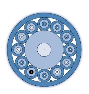
179
180 Hotline: Freephone number Tel: CORNING Fax: Customer Service Center Corning House, The Guildway, Old Portmouth Road Guildford, Surrey, GU3 1LR Great Britain Customer Service Center Postfach Neustadt/Coburg Germany France, Spain, Italy, UK Freephone number Tel: CORNING Fax: Germany, Austria, Switzerland Tel: Fax: nv.kunden.service@corning.com All other countries Tel: Fax: pn.cs@corning.com Visit us on the Internet cablesystems/europe
181 Hotline: Freephone number Tel: CORNING Fax: Customer Service Center Corning House, The Guildway, Old Portmouth Road Guildford, Surrey, GU3 1LR Great Britain Customer Service Center Postfach Neustadt/Coburg Germany France, Spain, Italy, UK Freephone number Tel: CORNING Fax: Germany, Austria, Switzerland Tel: Fax: nv.kunden.service@corning.com All other countries Tel: Fax: pn.cs@corning.com Visit us on the Internet cablesystems/europe

182 COPYRIGHT 2002 Corning Cable Systems GmbH & Co. KG P.O. Box Munich, Germany All rights reserved. This publication must not be reproduced or copied in any way whatsoever without the express consent in writing of Corning Cable Systems GmbH & Co. KG. Subject to availability and technical modifications. Corning Cable Systems GmbH & Co. KG reserves the right to improve, enhance or otherwise modify Corning Cable Systems products without prior notification, including and in particular technical data and other information about such products. There is no legal obligation to supply a specific product to a precise specification until a binding order is accepted by Corning Cable Systems GmbH & Co. KG. C1-N4-K Printed in Germany CCS FutureLink Modular Fiber Optic Cabling System Issue 1 CORNING CABLE SYSTEMS Carrier Networks Private Networks OEM Data Centers Project Services
FiberSolutions. Fiber Optic Cable & Assembly Solutions
 Solutions Optic Cable & Assembly Solutions Solutions MOHAWK FIBER OPTIC CABLE AND ASSEMBLY SOLUTIONS Today s fast paced world places an unyielding burden on data centers to deliver high performance and
Plug & Play Universal Harness, SMF-28 Ultra Single-mode (OS2)
") Plug & Play Universal Systems Harnesses have a pinned (male) MTP connector on one end that connects to a Plug & Play Universal Systems trunk or extender trunk, while the other end is equipped with single
Plug & Play Universal Systems Harnesses have a pinned (male) MTP connector on one end that connects to a Plug & Play Universal Systems trunk or extender trunk, while the other end is equipped with single
EDGE Solutions Trunk Cable, OM4, Low- Loss, MTP to MTP, 12 fibres
 EDGE MTP trunks are preterminated cables with 12 -fibre MTP connectors or LC duplex connectors on either side. The trunks build up the major skeleton of the passive network infrastructure, and thanks to
Fiber Optical Cabling Infrastructure Offer
 Fiber Optical Cabling Infrastructure Offer Zipcord Distribution Subunitized Distribution Armored Subunitized Distribution In/outdoor Distribution Armored In/outdoor Distribution Stranded Loose Tube High-Speed
Pretium EDGE Solutions Trunk Cable, OM3, Low-Loss, MTP to MTP, 24 fibres
 Corning LANscape Pretium EDGE (Evolved-Density, Growth -Enabled) solutions are high -density preterminated optical cabling systems that simplify installation and improve performance in data centre environments.
Structured (premises) wiring systems: building backbone (riser) and/or horizontal cabling.
 wiring systems: building backbone (riser) and/or horizontal cabling.") GIBT Breakout Cables Indoor I-V(ZN)HH 05-0- v6.0 Ordering Information Belden Part Numbers Fibre Description / count 4 6 8 4 6.5/5-OM GIBT0 GIBT04 GIBT06 GIBT08 GIBT GIBT4 50/5-OM BI GIBT0 GIBT04 GIBT06
GIBT Breakout Cables Indoor I-V(ZN)HH 05-0- v6.0 Ordering Information Belden Part Numbers Fibre Description / count 4 6 8 4 6.5/5-OM GIBT0 GIBT04 GIBT06 GIBT08 GIBT GIBT4 50/5-OM BI GIBT0 GIBT04 GIBT06
OPTICAL FIBER INTRODUCTION
 OPTICAL FIBER INTRODUCTION Advantages of optical fiber as compared to copper cables are known. They feature a very high degree of isolation, as they are immune to crosstalk, electromagnetic interference
Fiber Optical Cabling Infrastructure Offer
 Fiber Optical Cabling Infrastructure Offer Zipcord Subunitized Armored Subunitized In/outdoor Armored In/outdoor Stranded Loose Tube High-Speed Fiber Cabling Systems FS.COM offers an extensive line of
Indoor Cable Application Note
 Application Notes Indoor Cable Application Note Issued November 2013 Abstract With the fast development of fiber optic communication technology and the trend of FTTX, indoor fiber optic cables are more
Optical Fiber for Today s Premises Applications
 Optical Fiber for Today s Premises Applications Tony Irujo Customer Technical Support Mgr. OFS Optical Fiber Division 508-347-8582 tirujo@ofsoptics.com 1 Copyright 2006 Fitel USA Corp., All rights reserved.
Pretium EDGE Solutions Trunk Cable, OM4, Low-Loss, MTP to MTP, 24 fibres
 Corning Cable 143 Pretium EDGE Solutions Trunk Cable, OM4, Corning Cable Systems LANscape Pretium EDGE (Evolved -Density, Growth -Enabled) Solutions are high density pre -terminated optical cabling systems
AMP ACT 1 INSTALLING PREMISES CABLING SYSTEM. Welcome!!! Instructor : Nicholas Yeo
 AMP ACT 1 INSTALLING PREMISES CABLING SYSTEM Welcome!!! Instructor : Nicholas Yeo AMP ACT 1 INSTALLING PREMISES CABLING SYSTEM Welcome!!! 2 Standards ISO CENELEC AS/NZS ANSI IEC CSA TIA EIA EN50173 AS/NZS
EDGE Solutions Hybrid Trunk, OM4, Low- Loss, MTP to LC Duplex Uniboot, 24 fibres
 EDGE MTP trunks are preterminated cables with 12 -fibre MTP connectors or LC duplex connectors on either side. The trunks build up the major skeleton of the passive network infrastructure, and thanks to
Draka Black Universal central tube cable 1000N central tube cable w 2 24 fibres, glass elements and black FireBur sheath, VDE U-DQ(ZN)BH Application a
BH Application a") 1000N central tube cable w 2 2 fibres, glass elements and black FireBur sheath, VDE UDQ(ZN)BH Application and installation This cable can be used for LAN and WAN backbones, telecom access lines, fibre
1000N central tube cable w 2 2 fibres, glass elements and black FireBur sheath, VDE UDQ(ZN)BH Application and installation This cable can be used for LAN and WAN backbones, telecom access lines, fibre
FLAME RETARDANT RIBBONIZED FIBER
 FLAME RETARDANT RIBBONIZED Applications Inter-equipment connections NEBS applications Features/Benefits Color coded fibers Suitable for use with standard ribbon connectors Half-inch minimum bend radius
AMP NETCONNECT XG FIBER SYSTEM
 AMP NETCONNECT XG FIBER SYSTEM The Complete High-Performance, Cost-Effective Optical Fiber Premises Cabling Solution for Supporting the Emerging Ten Gigabit Networks von mit freundlicher Genehmigung von
EDGE8 MTP Trunk Cable
 The EDGE8 trunks utilise 8 -fibre push/pull optical connectors that are pinned on both ends of the cable. The trunks are shipped with strain -relief clips that allow for tool -less installation in EDGE8
Fiber Selection and Standards Guide for Premises Networks
 Fiber Selection and Standards Guide for Premises Networks WP1160 Issued: November 2012 Supersedes: October 2007 Authors: Carl Roberts and Dr. Russell Ellis Introduction There are several main types of
1 of 5 12/31/2008 8:41 AM
 1 of 5 12/31/2008 8:41 AM SAVE THIS EMAIL THIS Close All multimode fiber is not created equal By Robert Reid Bandwidth, reach, and cost are among the key factors you ll need to weigh. Multimode fiber cabling
OPTICAL CABLE & CABLE ASSEMBLY
 OPTICAL CABLE & CABLE ASSEMBLY FIBER OPTIC INDOOR CABLE MM 50 m (OM2) MULTI LOOSE TUBE CABLE Indoor Thight Buffer LSOH, 4 core NVLINMM2004LSOH MM 62.5 m MM 50 m (OM2) MM 50 m (OM3 550+/ OM4) Direct Burial
THE NEW OPTICAL FIBRE CATEGORIES What do they promise?
 THE NEW OPTICAL FIBRE CATEGORIES What do they promise? prepared and delivered by ϕ Breakfast Seminar 13th March 2001 Fibreoptic Industry Association PO Box MT65 LEEDS LS17 8YD UK Tel: +44 (0) 113 232 3721
Basic Fiber Optic Concepts
 Basic Fiber Optic Concepts Advantages of Fiber Optics A signal can be sent over long distances (200 Km/125 miles) without the need for regeneration Not sensitive to electromagnetic or radio frequency
EDGE Solutions Trunk Cable, SMF-28 Ultra OS2, MTP to MTP, 12 fibres
 EDGE MTP trunks are preterminated cables with 12 -fibre MTP connectors or LC duplex connectors on either side. The trunks build up the major skeleton of the passive network infrastructure, and thanks to
9/27/04 cci Cablecom Inc. 1
 cci Cablecom Inc. 1 CCI Cablecom Inc. is a privately held, women owned corporation headquartered in Aurora, CO. We manufacture a variety of voice and datacom products. Cable applications Include: Local
MTP Outdoor Cabling System
 The AFL MTPE (MTP Elite) Low Loss outdoor cabling system offers a market leading, low loss, fast and efficient connection system for underground (UG) and outside plant applications. These assemblies offer
Fiber Optical Cabling Infrastructure Offer
 Fiber Optical Cabling Infrastructure Offer OEM and Custom Zipcord Distribution Subunitized Distribution Armored Subunitized Distribution In/outdoor Distribution Armored In/outdoor Distribution Cable Structure
Strength member Waterblocked EGlass fibre elements Sheath 1.0 mm black FireBur sheath, UV stabilised, IEC Sheath marking Draka I/O CT LSHF 1.
 1000N central tube cable w 2 2 fibres, glass elements and black FireBur sheath, VDE UDQ(ZN)BH Application and installation This cable can be used for LAN and WAN backbones, telecom access lines, fibre
Cabling Solutions Data Center & Local Area Networks
 Cabling Solutions Data Center & Local Area Networks R&M About us. «R&M is a leading provider of cabling solutions for high quality communication networks.» R&M (Reichle & De-Massari AG) has developed and
Pretium EDGE Solutions Trunk Cable, 50 µm multimode (OM3)
") Pretium EDGE 133 Pretium EDGE Solutions Trunk Cable, 50 Pretium EDGE Solutions trunk cables utilize the MTP Connector, a 12 -fiber push/pull optical connector with a footprint similar to the SC simplex
Pretium EDGE 133 Pretium EDGE Solutions Trunk Cable, 50 Pretium EDGE Solutions trunk cables utilize the MTP Connector, a 12 -fiber push/pull optical connector with a footprint similar to the SC simplex
SPEC SHEET. Multimode Patch Cords and Pigtails. Cable types. Description. Features. Fiber types
 Multimode Patch Cords and Pigtails SPEC SHEET Description ADC KRONE offers a wide array of multimode fibre optic patch cords featuring Riser and LSZH cables in various diameters. ADC KRONE s multimode
Data Center Product Summary
 Data Center Product Summary Table of Contents Introduction...3 Building Access Cables: Outside Plant Ribbon Cables...4 Indoor & Indoor/Outdoor Ribbon Cables...5 Outside Plant MicroDuct Cables...6 Inside
Data sheet PM PCC OpDAT patch cord LC-D/LC-D OM3 aqua, 20.0 m
 Illustrations Dimensional drawing Page 1/5 See enlarged drawings at the end of document Product specification patch cord for the METZ CONNECT Patch Management System multi mode patch cord I-V(ZN)H 50/125
Plug & Play Universal Low-Loss Systems A LANscape Pretium Solutions Product
 Applications Data Center LAN/SAN Enterprise Building Backbone -to-the-desk Description Plug & Play Universal Systems are preterminated optical fiber cabling systems designed to dramatically improve performance
ADVENTUM OUTDOOR / INDOOR FIBER OPTIC CABLE
 ADVENTUM OUTDOOR/INDOOR FIBER OPTIC CABLE ADVENTUM OUTDOOR / INDOOR FIBER OPTIC CABLE Adventum can reduce outdoor/indoor fiber installation costs by as much as 26%*. Plenum or riser rated. Indoor or outdoor.
Plug & Play Universal Systems
 100G Ready performance Maximum skew of 0.75 ns Product is assured to work in parallel optic applications for Ethernet, Fibre Channel and InfiniBand MTP /LC Duplex Module TRAINING SPLICE EQUIPMENT High-density
Alternative Energy Solutions
 Alternative Energy Solutions Fiber Optic Cabling Solutions for Wind and Solar Farms VISIT US AT WWW.OFSOPTICS.COM Centralized Wind and Solar Farm Automation The power network is changing. It needs the
E-DAT C6A. The compact connection system of course with Cat.6A
 E-DAT C6A The compact connection system of course with Cat.6A Intelligent system solution for structured cabling Nowadays the need for high data transfer rates is enormous. This not only applies to public
MTP Multi Lite Trunk Assemblies
 MTP Multi Lite Trunk Assemblies MTP Multi-Lite Trunk assemblies are a neat solution for providing up to four MTP -MTP links within a compact, high density ruggedised cable. The cable construction consists
Siemon PON Fiber Cabling Solutions
 Siemon PON Fiber Cabling Solutions WWW.SIEMON.COM 8 Siemon Enterprise PON Fiber Cabling Solution Siemon Enterprise Passive Optical Network (PON) Fiber Cabling Solution improves the modularity, flexibility
Telecommunications Structured Cabling Systems
 Section 18 Telecommunications Structured Cabling Systems 18.1.0 Introduction 18.1.1 Important Codes and Standards 18.1.2 Comparison of ANSI/TIA/EIA, ISO/IEC, and CENELEC Cabling Standards 18.2.0 Major
High speed to the antenna with 10 to 100 G interconnections
 High speed to the antenna with 10 to 100 G interconnections High speed mobile network solutions Ever increasing mobile bandwidth calls for broadening the required capacity in wireless backhaul and data
Opt-X Enterprise Fiber Trunk Cables
 APPLICATION Factory-terminated and tested fiber trunk cables connect central patching locations to zones or pods. Available terminated with both modular (MTP ) and discrete connectors, these trunks are
FTTE Revisited for New Technologies
 FTTE Revisited for New Technologies A new look into FTTE design to allow great flexibility as well as compliance to the latest 40G and 100G. Gautier Humbert, RCDD, CDCDP Business Development Manager Eastern
STAR. Data Center High Density Connectivity Solution
 STAR Data Center High Density Connectivity Solution 2 STAR Solution Illustration Reach for the STAR: Data Center Connectivity that achieves new heights! Fibernet is proud to introduce the new STAR series,
Best standard: Our FO components
 Best standard: Our FO components Added value 5 Assortment Production 8 Our company 9 Data intensive applications require connections with the highest trans mission rates. Alongside system solutions, HUBER+SUHNER
QuickSpecs. Models. Features and Benefits Connectivity. HP V2124 Switch. HP V2124 Switch. Overview
 Overview Models J4868A Key features Unmanaged plug-and-play operation 24 10/100 ports One transceiver slot for 100Base-FX connectivity Rack mountable with included hardware Industry-leading warranty Product
Singlemode vs Multimode Optical Fibre
 Singlemode vs Multimode Optical Fibre White paper White Paper Singlemode vs Multimode Optical Fibre v1.0 EN 1 Introduction Fibre optics, or optical fibre, refers to the medium and the technology associated
barpa Values Website & Social Network
 barpa Hello! Welcome to our world. Have you heard about us? We are specialized in structured cabling systems for data networks. We are able to give you the full range, from cable to cabinets, fiber optic
Using Laser-Optimized Multimode Fiber for 1 and 10 Gigabit Campus Backbone Applications
 Using Laser-Optimized Multimode Fiber for 1 and 10 Gigabit Campus Backbone Applications David Kozischek, Market Manager Enterprise Networks, Corning Optical Communications Systems engineers at Corning
Polymer Coated Fiber Cable (PCF)
") Polymer Coated Fiber Cable (PCF) Panduit has introduced a Polymer Coated Fiber (PCF) to their fiber cable offering available in 50µm and 62.5µm core diameters. Along with this cable having a stronger durability
Polymer Coated Fiber Cable (PCF) Panduit has introduced a Polymer Coated Fiber (PCF) to their fiber cable offering available in 50µm and 62.5µm core diameters. Along with this cable having a stronger durability
P R O D U C T C AT A L O G T ALOG
 2 0 0 2 2002 PRODUCT CATALOG Need More Information? Visit our Web site at Instruction Sheets Cut Sheets White Papers Data Sheets Product/Part Number Searches AMP NETCONNECT Sales Engineer Contacts Authorized
Data Center & Cloud Computing Infrastruture Solutions DATASHEET. MTP/MPO-LC Breakout Cable Aseemblies High Density Cabling System
 Data Center & Cloud Computing Infrastruture Solutions DATASHEET MTP/MPO-LC Breakout Cable Aseemblies High Density Cabling System REV.2.0 2018 MTP/MPO Breakout Cable 01 Description MTP/MPO breakout assemblies
Multifiber Full Breakout Cable Assemblies
 Product updated on November 21, 2018 Multifiber Full Breakout Cable Assemblies Multicore full breakout cable assemblies are ideal for short cable runs where a direct connection to equipment or panels is
LC Connector. A High Density Fiber Optic Network Solution. Paul Kolesar Lucent Technologies, Bell Laboratories
 A High Density Fiber Optic Network Solution Paul Kolesar Lucent Technologies, Bell Laboratories IEEE 802.3z Gigabit Ethernet March, 1997 Outline Design Background and Goals Product Family Overview Features
SC/APC Connector. CATV Active device Telecommunication. Metro Local Area Data processing
 Introduction As the industry s leading supplier of single-mode cable assemblies, Optical Fiber offers the most complete line of connectors and factory-terminated cables. From single-fiber jumpers to high
Pre-Terminated. FiberExpress
 FiberExpress Pre-Terminated Product Bulletin PB141E LSNH ssemblies The new line of Belden low-smoke, no-halogen (LSNH) pre-terminated fiber assemblies offers faster data center deployment, better performance
Cables Fiber & Copper
 Updated in 2017 Free Product Guide for Your Network Cables Fiber & Copper Catalog FS.COM Fiber & Copper Cable This catalog is a guide of FS.COM fiber and copper cables including standard LC/SC patch cables,
Uniprise Structured Cabling Solutions Guide
 Uniprise Structured Cabling Solutions Guide Exceptional value, proven reliability You re not unrealistic. You re simply looking for a reliable and affordable structured cabling solution; a single portfolio
ANSI/TIA/EIA-568-B Cabling Standard
 83 Pair Numbers and Color Coding The conductors in a UTP cable are twisted in pairs and color coded so that each pair of wires can be easily identified and quickly terminated to the appropriate pin on
Application Note. Data Center Standards and Layouts
 Application Note Data Center Standards and Layouts 1. Data Center Standards In earlier times, a room in which one or more servers, a telephone system and active network components were located was often
GALLIA EST OMNIS DIVISA. AeroLink TM ADSS Cables
 GALLIA EST OMNIS DIVISA AeroLink TM ADSS Cables About Us Prysmian (formerly Pirelli) has been in the cabling business for over 125 years, operating with 53 manufacturing plants and more than 12,000 employees
Cabling Infrastructure
 Introduction Ethernet Banking on Structured Cabling Technology Drivers Classification of Cables Fibre-optic cable Cables in building Cabling Infrastructure Cabling systems address the networking requirements
HIGH DENSITY DATA CENTER CABLING GUIDE. Optics DACs Cables Cable Management Fiber TAPs Media Converters
 HIGH DENSITY DATA CENTER CABLING GUIDE Optics DACs Cables Cable Management Fiber TAPs Media Converters PROVIDING MTP CABLING SOLUTIONS FOR THE SMART DATA CENTER. APPROVED NETWORKS SETS THE STANDARD The
Cisco Small Form-Factor Pluggable Modules for Gigabit Ethernet Applications
 Data Sheet Cisco Small Form-Factor Pluggable Modules for Gigabit Ethernet Applications The industry-standard Cisco Small Form-Factor Pluggable (SFP) Gigabit Interface Converter is a hot-swappable input/output
OMEGA MODULAR PATCH PANEL EMPTY ENCLOSURE
 OMEGA MODULAR PATCH PANEL EMPTY ENCLOSURE The Omega MPP enclosure is based on a 19" frame, with 4 empty module slots for MPP modules. Highly flexible : any mix between twisted pair and optical fiber modules.
OM5 versus OM4 Solution concepts and potential applications WHITEPAPER
 OM5 versus OM4 Solution concepts and potential applications The OM5 fiber is the latest member in the 50 µm multimode fiber family. The reason for the development of this new fiber type is that the continuous
Tarleton State University. Specifications
 Tarleton State University Campus Communication Infrastructure Specifications Cabling Standards Summary This document identifies Tarleton State University communication infrastructure standards. The communication
200-micron Fiber Enables New Cable Designs
 White Paper 200-micron Fiber Enables New Cable Designs Since single-mode fiber was first introduced in the early 1980 s, little has changed in its basic geometric parameters. The core size has remained
Splice Trays An Evolant Solutions Product
 Applications For use with indoor or outdoor splice hardware Protects and manages fibers and fiber splices Used at field splice, transition splice and end splice locations Description splice trays use proven
The following pages contain a guide for the installation
 INDEX The goal of this section is to illustrate how Siemon Company products can be used to support some of the most popular and emerging networks on the market. Section Contents 100Base-T....................................
Fiber Design for Traffic Signals and ITS Projects
 Fiber Design for Traffic Signals and ITS Projects PRESENTER: Mike Lubin ATKINS National ITS (Atlanta) Sr. Network Engineer 16 Years Telecom Experience 13 Years with ATKINS Sr. Network Engineer ITS Network
Fiber backbone cabling in buildings
 White paper Fiber backbone cabling in buildings www.commscope.com 1 Contents Introduction 3 Backbone cabling speeds 3 Optical fiber in the backbone 3 10 Gbps optical fiber backbone 3 Migrating to 40 Gbps
QuickSpecs. Models HP G Switch
 Overview Models HP 1410-8G Switch HP 1410-16G Switch HP 1410-24G Switch HP 1410-8 Switch HP 1410-16 Switch HP 1410-24 Switch HP 1410-24-R Switch HP 1410-24-2G Switch J9559A J9560A J9561A J9661A J9662A
Cabling Excellence for Open Architecture MOHAWK
 Cabling Excellence for Open Architecture MOHAWK Security Technology in the security sector is evolving at a rapid pace. Mohawk keeps security companies at the forefront of their industry with cabling solutions
Volition. Multimode VF-45 Socket and Patch Cords. 3Innovation
 Volition Multimode VF-45 Socket and Patch Cords O b D s oc ol e um te en t It's as easy as plugging in a rj-45. The Volition VF-45 Socket and Patch Cords from 3M are the latest duplex, fiber optic interconnects
Volition. Multimode VF-45 Socket and Patch Cords. 3Innovation
 Volition Multimode VF-45 Socket and Patch Cords It's as easy as plugging in a rj-45. The Volition VF-45 Socket and Patch Cords from 3M are the latest duplex, fiber optic interconnects for affordable, high
How to Decide on Optical Fibre Termination Options. Thomas Ko, RCDD Product Manager Tyco Electronics / AMP NetConnect
 How to Decide on Optical Fibre Termination Options Thomas Ko, RCDD Product Manager Tyco Electronics / AMP NetConnect Termination Choices Optical Fiber Cabling in Data Center Options available Traditional
SUMITOMO SPECIFICATION. FutureFLEX. Multimode 62.5 µm Core Optical Fiber (OM1) Gigabit Grade
 Gigabit Grade") SUMITOMO SPECIFICATION FutureFLEX Multimode 62.5 µm Core Optical Fiber (OM1) Gigabit Grade SUMITOMO ELECTRIC LIGHTWAVE CORP. 201 South Rogers Lane, Suite 100, Raleigh, NC 27610 (919) 541-8100 or 1-800-358-7378
SUMITOMO SPECIFICATION FutureFLEX Multimode 62.5 µm Core Optical Fiber (OM1) Gigabit Grade SUMITOMO ELECTRIC LIGHTWAVE CORP. 201 South Rogers Lane, Suite 100, Raleigh, NC 27610 (919) 541-8100 or 1-800-358-7378
Cisco 10GBASE SFP+ Modules
 Data Sheet Cisco 10GBASE SFP+ Modules Product Overview The Cisco 10GBASE SFP+ modules (Figure 1) offer customers a wide variety of 10 Gigabit Ethernet connectivity options for data center, enterprise wiring
Optical Fiber Networks: Industry. and New Options for Networks
 Optical Fiber Networks: Industry Trends, Application Influences and New Options for Networks Herbert V Congdon II, PE Manager, Standards & Technology Tyco Electronics AMP NETCONNECT Solutions Preview Deciding
IBDN 110 Cross-Connect System
 IBDN 110 Cross-Connect System Connecting & Wiring Blocks Cross-Connect Kits Wall Mount Frame Kits Patch Cords Labels & Management Accessories For For A Complete End-to-End 110 Solution what s coming next.
FMT4S. High Density Connectivity Solution
 FMT4S High Density Connectivity Solution 2 FMT4S Solution Illustration FMT4S Optical Distribution Frame (ODF) FMT4S series is an advanced ODF series offering premium quality Data Center connectivity solution.
Models HP G Switch
 Overview Models HP 1410-8G Switch HP 1410-16G Switch HP 1410-24G Switch HP 1410-8 Switch HP 1410-16 Switch HP 1410-24 Switch HP 1410-24-2G Switch J9559A J9560A J9561A J9661A J9662A J9663A J9664A Key features
Wideband Multimode Fiber What is it and why does it make sense?
 White Paper Wideband Multimode Fiber What is it and why does it make sense? March, 2015 Contents Executive summary 3 A brief history of MMF 3 The role of fiber connectors 4 Introducing WBMMF 5 2 Executive
FO Field Genuine alternative to splicing
 FO Field Genuine alternative to splicing Get more Flexibility Cabling freedom Efficiency Easy mounting Reliability Long-term stability Flexibility. Cabling freedom. Start independently Freedom in fiber
Frequently Asked Questions (FAQs) Siemon 10G ip Solutions
 Siemon 10G ip Solutions") Frequently Asked Questions (FAQs) Siemon 10G ip Solutions The world of enterprise cabling is evolving rapidly. Emerging, high-bandwidth services and the adoption of higher speed Ethernet standards, like
Frequently Asked Questions (FAQs) Siemon 10G ip Solutions The world of enterprise cabling is evolving rapidly. Emerging, high-bandwidth services and the adoption of higher speed Ethernet standards, like
Plug & Play Universal Trunks
 1 1 22.88 115 0 Plug & Play 0 Plug & Play Universal Trunks Plug & Play Universal Systems MTP Trunks provide the backbone of the Plug & Play System. With non - pinned MTPs on both ends of the cable, these
Product Selection Guide
 Product Selection Guide If you are in the process of selecting network infrastructure products for a future project, you will find a variety of performance levels available. Data speeds and throughput
Pre-terminated Multi Fibre Cable Assemblies
 AFL manufactures a broad range of factory terminated and tested multi-fibre cable assemblies. These assemblies are available in various fibre types and counts, cable constructions and connector options.
Multifibre Full Breakout 1.6mm Cable Assemblies
 Product updated on November 14, 2017 Multifibre Full Breakout 1.6mm Cable Assemblies Item Description Multicore full breakout cable assemblies are ideal for short cable runs where a direct connection to
PATCH-CORD. SC Patch-Cord APPLICATIONS AVAILABILITY FEATURES SPECIFICATIONS. Active device termination Local Area Networks (LANs)
") SC Patch-Cord APPLICATIONS CATV Metro Test equipment Active device termination Local Area Networks (LANs) Premise installations Telecommunicatio n networks Data processing networks Wide Area Networks (WANs)
SC Patch-Cord APPLICATIONS CATV Metro Test equipment Active device termination Local Area Networks (LANs) Premise installations Telecommunicatio n networks Data processing networks Wide Area Networks (WANs)
13-SDMS-01 REV SDMS-01, REV.00 SEC DISTRIBUTION MATERIALS SPECIFICATION DATE: G
 13-SDMS-01 REV. 00 SPECIFICATIONS FOR FIBER OPTIC CONNECTIVITY COMPONENTS (PATCH CORDS, PIGTAILS, FAN-OUT CABLES AND CONNECTORS FOR INTERNAL INSTALLATIONS) This specification is property of SEC and subject
Cisco 100GBASE QSFP-100G Modules
 Data Sheet Cisco 100GBASE QSFP-100G Modules Product Overview The Cisco 100GBASE Quad Small Form-Factor Pluggable (QSFP) portfolio offers customers a wide variety of high-density and low-power 100 Gigabit
Signature Core Fiber Optic Cabling System
 White Paper June 2012 WP-17 Signature Core Fiber Optic Cabling System Multimode Fiber: Understanding Chromatic Dispersion Introduction The performance and reliability of networks within the Data Center
Panduit Certified Installer. Fiber Certification Review
 Panduit Certified Installer Fiber Certification Review 2 What does the cleave tool do? A. Breaks the glass cleanly B. Cuts the glass cleanly C. Scores the glass cleanly D. Shatters the glass cleanly Breaks
MTP Cabling Overview. MTP Cabling System
 MTP cabling architectures utilise varying cable and patchcord configurations as defined in TIA-568-C.0-2. These cables vary by gender, fibre orientation and pair management. AFL manufactures a large and
Retired. IEEE 802.1p prioritization: delivers data to devices by honoring the priority and type of traffic
 Overview HP V1400-8G Switch HP V1400-24G Switch Models HP V1400-24G Switch HP V1400-8G Switch Key features Unmanaged Layer 2 Gigabit switch 8- and 24-port models Fanless switch for silent operation Two
Fiber Backbone Cabling in Buildings
 White Paper Fiber Backbone Cabling in Buildings www.commscope.com Contents Introduction 3 Backbone Cabling Speeds 3 Optical Fiber in the Backbone 4 b/s Optical Fiber Backbone 4 Migrating to 40 Gbps and
CELL SITE INFRASTRUCTURE SOLUTIONS. Creative Solutions for the Mobile Evolution
 CELL SITE INFRASTRUCTURE SOLUTIONS Creative Solutions for the Mobile Evolution Macro Tower Micro Pico Base Station COW / COLT Roof Top Typical Macro Tower Application Typical COW / COLT Application Amphenol
2001 PRODUCT CA T ALOG
 2001 PRODUCT CATALOG 2001 Need More Information? Visit our Web site at Instruction Sheets Cut Sheets White Papers Data Sheets Product/Part Number Searches AMP NETCONNECT Sales Engineer Contacts Authorized