Page 2 262/264 LaserMount User s Manual. Table of Contents
|
|
|
- Hillary Griffin
- 6 years ago
- Views:
Transcription


1
2 Page 2 262/264 LaserMount User s Manual Table of Contents Introduction... 3 Safety Terms and Symbols... 3 Installation and Use... 4 Connector Pin-Outs... 7 Technical Specifications... 9 Mechanical Drawings Using the Thermistor on Standard Versions Using the RTD on 150 C Versions Operating at High Temperatures Laser Diode Protection Warranty Maintenance and Service... 23
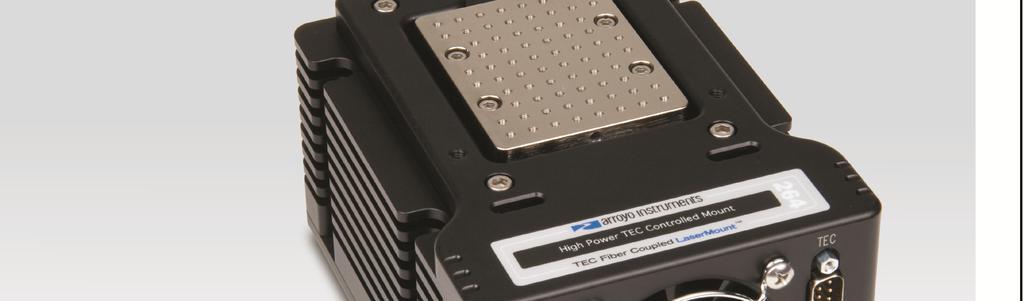
3 262/264 LaserMount User s Manual Page 3 Introduction Thank you for choosing the 262/264 LaserMount from Arroyo Instruments. The 262/264 LaserMount is designed for high performance and long term use. The 264 LaserMount integrates a large 120W Peltier cooler for precise control and substantial heating and cooling capacity for your powerful devices. The standard 264 LaserMount has an operating range of +15 C to +85 C, and the 150 version allows operation up to 150 C, covering a broad range of temperature control needs. The 262 LaserMount provides passive cooling with very low C/Watt thermal rise. The 262/264 LaserMount comes standard with an integrated fan for additional cooling capacity. When used with the 5300 Series TECSource temperature controllers, no additional power supply is needed to power the fan, or use a standard external 12V DC power supply when connecting to other temperature controllers. The 262/264 LaserMount also offers all the features you would expect from a modern diode fixture, including: Hard nickel over 100% oxygen free copper thermal plate. Designed to be quickly integrated with Arroyo s LaserSource and TECSource instruments. Industry-standard D-sub connectors and pin-outs allow for quick integration into existing laser applications. Safety Terms and Symbols The following safety-related terms are used in this manual: Warnings (noted by the WARNING heading) explain dangers that could result in physical injury or death; Cautions (noted by the CAUTION heading) explain conditions that could result in damage to the instrument, other equipment, or your device. Notes (noted by the NOTES heading) are not safety-related, and are intended simply to point out important information. If, at any time, any of the following conditions exist, or are suspected of existing, discontinue use of the unit until it can be inspected by qualified service personnel:
4 Page 4 262/264 LaserMount User s Manual Visible damage to the unit, including damage or stress caused during product shipment; Storage of the unit outside the standard storage temperature or humidity rating, or prolonged storage under harsh conditions; Failure to operate properly. If needed, contact your distributor or Arroyo Instruments for service or repair to ensure the safety of the product is maintained. Installation and Use The 262/264 LaserMount is an easy to use mount. It typically comes preconfigured for your device, so simply mount the device onto the plate using the holes provided, and make the electrical connections to the device. If you are using an Arroyo Instruments 5300 Series TECSource temperature controller, the fan supply is built directly into the TECSource. You will need to enable the fan supply in the TECSource menu see the TECSource manual for additional details on how to do that. If you are using a third-party temperature controller, then you will need to provide a 12V DC power supply through the DB-15 connection. See the pinout below for the fan pin assignments. NOTE Earth Grounding Considerations The DB-9 or 9W4 and DB-15 connector shells are electrically connected to the housing and 8mm banana jack. Depending on the wiring of your cables and instruments, this may or may not provide earth grounding of the fixture. Make sure the cable shell is earth grounded on both ends of the cable, and that the instrument makes connection from its connector to earth ground. If in doubt, you can also use a grounding strap from the 8mm banana jack directly to earth ground.
5 262/264 LaserMount User s Manual Page 5 WARNING The mount is capable of producing high temperatures on the mounting plate, which can cause burns to skin or other objects that come in contact with the mounting plate. Connect to Laser Diode Driver and TEC Controller: Next, connect the 262/264 LaserMount to your laser diode driver and temperature controller. If using the 264, Make sure the temperature controller s current limit is set to a maximum value of 7.4A. If using the 262 and connecting the temperature controller to your device, ensure that the maximum current for your device is properly set on the temperature controller. For 150 C versions, make sure to adjust the RTD coefficients to their proper values, or the temperature measurement and set point will not be correct. See Using the RTD on 150 Versions, below, for more information. The 262/264 LaserMount will be equipped with either a DB-9or 9W4 male connector for the laser. The DB-9 is used for lower power applications, usually no more than 10A, while the 9W4 supports up to 20A operation. Where possible, we recommend the use of Arroyo Instruments laser and TEC cables. Use p/n 1264 TECSource Cable for the temperature controller connection, and LaserSource cable as appropriate for your fixture. NOTE Arroyo Instruments offers Laser and TEC cables designed to connect directly between our LaserSource and TECSource products. If you use your own cables, ensure the connections are properly made between the instrument and the mount, and that proper grounding techniques are used. The pin-out of the connectors can be found later in this document.
6 Page 6 262/264 LaserMount User s Manual CAUTION Be sure you are properly ESD protected before handling your laser. For additional information, read the section titled Laser Diode Protection later in this manual. Mounting Plates The 262/264 LaserMounts are available with a variety of different mounting plates. The most common plate is the BB plate, which is a grid of mounting holes, much like an optical bread board (hence the BB desgination). There are two BB configurations: 264-BB 2-56 holes on 0.25 centers 264M-BB M2.5 holes on 6.25mm centers There is also a standard 264 Plate, detailed on page 14 below, which accepts a wide variety of device types. Because the specific model number of the 264 varies depending on the device termination requirements, please contact the factory for the appropriate 264 part number. To designate the connector type, add a -DB9 or -9W4 to the end for a DB-9 male connector or 9W4 male connector, respectively. For 150 C mounts, add a -150 to the end of the part number. Additional configurations are available, including custom machined plates, contact the factory for details.

7 262/264 LaserMount User s Manual Page 7 Connector Pin-Outs 262/264 LaserMount Rear Connectors DB-9 Pin Description 1 & 2 No Connection 4 & 5 Laser Cathode 6 Photodiode (PD) Cathode 7 Photodiode (PD) Anode 8 & 9 Laser Anode Laser DB-9 Connector Pin-Out 9W4 Pin Description A1 Laser Anode A2 No Connection A3 Laser Cathode A4 No Connection Signal Pins No Connection Shell Earth Ground Laser 9W4 Connector Pin-Out
8 Page 8 262/264 LaserMount User s Manual DB-15 Pin Description 1, 2, & 9 TE (+) 3, 4, & 10 TE ( ) 7 Thermistor or RTD (+) 8 Thermistor or RTD ( ) 11 FAN (+) 12 FAN ( ) 13 No connection 14 RTD Sense (+) 15 RTD Sense ( ) TEC DB-15 Connector Pin-Out Sensor Polarity and 4-Wire Connections While the thermistor and RTD inputs are not polarized, when using a 4-wire RTD connection to the mount, it is important to properly connect the polarity of the sense wires to the sensor. Pins 7 and 14 should be one polarity (+) and pins 8 and 15 should be the opposite polarity ( ). If polarities are not matched, the instrument will indicate a sensor error.
9 Technical Specifications FICATIONS 262/264 LaserMount LASER PACKAGE SUPPORTED Package 262/264 LaserMount User s Manual Page 9 Various high power devices TEMPERATURE CONTROL (264 only) Standard Version Temperature Range ( C) +15 to +85 Sensor Type BetaTHERM 10K3A1IA 10kΩ Thermistor High Temperature Version Temperature Range ( C) +15 to +150 Sensor Type 100Ω Platinum RTD Ω / Ω / C TE Module Imax = 7.4A Vmax = 16.4V INPUT CONNECTORS Laser Diode DB-9, male or 9W4, male Temperature Controller DB-15, male GENERAL Fan 12VDC, 210mA max Size (H x W x D) [in(mm)] 3.0 (76.2) x 4.5 (114.3) x 6.0 (152.4) Mounting holes Four holes for ¼-20 screws
10 Page /264 LaserMount User s Manual Mechanical Drawings Figure 1 - Top View of the 262
11 262/264 LaserMount User s Manual Page 11 Figure 2 - Detail View of the 262 Mounting Holes
12 Page /264 LaserMount User s Manual Figure 3 - Top View of the 264
13 262/264 LaserMount User s Manual Page 13 Figure 4 - Detail View of the 264 Standard Cold Plate Mounting Holes
14 Page /264 LaserMount User s Manual Mounting Locations for 264 Standard Cold Plate Butterfly SP package Alfalight AM6 package 2-56 screws x screws x screws x 4 Lumics TO package STAR LED JDSU L4, screws x screws x screws x 2 JDSU L screws x 4
15 262/264 LaserMount User s Manual Page 15 Figure 5 - Detail View of the 264-BB Cold Plate Mounting Holes Figure 6 - Detail View of the 264M-BB Cold Plate Mounting Holes
16 Page /264 LaserMount User s Manual Figure 7 - Rear View of 260 Series, DB9 Figure 8 - Rear View of 260 Series, 9W4
17 262/264 LaserMount User s Manual Page 17 Figure 9 - Front View of 260 Series Using the Thermistor on Standard Versions The standard version of the 264 LaserMount is equipped with a 10kΩ negative temperature coefficient (NTC) thermistor, specifically, the BetaTHERM 10K3A1. A thermistor works by translating temperature into resistance, with resistance decreasing as temperature increases (hence the negative coefficient ). Below is the response curve of the thermistor: Resistance (Ω) Temperature ( C) Resistance vs. Temperature Graph
18 Page /264 LaserMount User s Manual As can be seen be the graph, the resistance of the thermistor drops very quickly. In the typical control range (0 C to 40 C), typical 10K thermistors offer good sensitivity to changes in temperature, and this is the range in which most 10K thermistors are typically used. 10K thermistors can be used at much higher temperatures, but will suffer poorer temperature stability performance because of the lower sensitivity. All Arroyo temperature controllers support operation using a 10μA or 100μA thermistor bias, which limits the upper control range to 450kΩ or 45kΩ, respectively. To minimize noise and maximize stability, you should select highest current while still allowing you full operation across your required temperature range. The typical setting is 100μA, but your application will determine the actual needs. The Steinhart-Hart Equation As can be seen from the temperature versus resistance graph above, resistance varies inversely with temperature in a non-linear fashion. This relationship can be accurately modeled by polynomial equations, and one such being the Steinhart- Hart equation: 1 T A B *ln( R) C *ln( R) 3 The coefficients for the BetaTHERM 10K3A1 thermistor are: A = x10-3 B = x10-4 C = x10-7 These are the default coefficients for Arroyo Instruments temperature controllers.
19 262/264 LaserMount User s Manual Page 19 Using the RTD on 150 C Versions The 150 C version of the 264 LaserMount is equipped with a RTD sensor with a Ω / Ω / C sensitivity. Like thermistors, RTDs also function by converting temperature into resistance, but unlike thermistors, RTDs increase in resistance as temperature increases. RTDs are also a fairly linear device, meaning they can be used across a much broader temperature control range. According to IEC751, the resistance/temperature relationship is determined using one of two equations, dependent on the temperature or resistance value being measured. For resistances above the R 0 value (resistance at 0 C, typically 100Ω, as is the case with the RTD used in the 264) of the RTD, the following equation is used: R R0 (1 AT BT Below R 0, an additional term is added to the equation: 2 R R0[1 AT BT C( T 100) T In both of these equations, R 0 is the resistance of the RTD at 0 C, and A, B, and C are the coefficients as defined by IEC751, through regression analysis, or by using the Callendar-van Dusen method. Not all Arroyo Instruments temperature controllers support RTD operation. Check with the factory for the recommended controller, as high temperature operation also has additional requirements for the controller (see Operating at High Temperatures, below). For the Arroyo Instruments controllers that support RTD sensors, the default coefficients are not correct for this mount. They must be changed to use the Ω / Ω / C curve, which has the following coefficients: A = x10-3 B = x10-6 C = x10-12 R 0 = 100 These coefficients can be changed in the Sensor menu. 2 ) 3 ]
20 Page /264 LaserMount User s Manual 2-Wire versus 4-Wire Measurements One concern in using RTDs are their relatively low resistance (typically 100Ω at 0 C), and small Ω/ C. Because of these two factors, the resistance of the cable used to connect to the sensor can become a significant error in the sensor measurement. Most Arroyo Instruments controllers offer two RTD measurement modes: a conventional two wire measurement mode, which is subject to this error, and a four wire measurement mode that uses separate sensor and source lines to remotely sense the actual resistance of the RTD and eliminate the cable or connector resistances. When using 4-wire measurement mode, you must select RTD (4-wire) as the sensor type, and then connect the Sensor+ and Remote Sensor+ at one side of the RTD, and Sensor and Remote Sensor to the other side of the RTD. Make these connections as close to the sensor as possible. The drawings below illustrate how 2-wire and 4-wire connections work. Note that 4-wire measurements require all four wires to be brought through the cable to the mount. The 1262 TECSource cable carries this connection through to the mount, but the 1260 cable does not. Temperature Controller Sensor+ Sensor Mount RTD Sensor RTD 2-wire Measurement Temperature Controller Sensor+ Remote Sensor+ Remote Sensor Sensor Mount RTD Sensor RTD 4-wire Measurement
21 Operating at High Temperatures 262/264 LaserMount User s Manual Page 21 The (150 C-capable version) has additional requirements that should be considered when operating in the upper temperature range: 1. The voltage requirements of the TEC increase significantly when operating at the higher temperatures, so much so that the standard 5305 or 6300 Series controllers will be voltage limited when controlling the mount. It is recommended that you purchase the controller, which has a 4A / 15V output, enough to provide the additional voltage needed by the mount, compared to the 5A / 12V outputs of the 5305 of 6300 Series controllers. Contact the factory for more details. 2. Turn off the mount fan when operating significantly above ambient. By turning off the fan, you reduce the cooling efficiency on the heat sink, which is desirable when operating at high temperature, and will reduce the amount of TEC power required to reach and maintain the target temperature. However, you may still need the fan if you will be operating the mount under heavy thermal load such that it is cooling even at elevated temperatures. Note that the body of the heat sink will become warm, and could reach temperatures of up to 50 C. Laser Diode Protection Electrostatic discharge and current spikes can be a significant cause of damage to laser diodes, but when proper precautions are taken, these risks can be greatly reduced or eliminated. Arroyo Instruments controllers offer state-of-art laser diode protection, but no instrument can fully shield the laser from damage. Please take these considerations into account when operating your laser: 1. Always set the current limit at or below the maximum current your laser can handle. This prevents the device from accidentally driving the current too high, either via the set point or from the modulation port. This also provides additional current limiting protection from ESD. 2. Always work in an ESD safe operating environment, including the use of wrist straps, ESD grounded work surfaces and floors, and ESD-safe tools. 3. Where the AC power to the laser driver to temperature controller may be noisy, use isolation transformers or uninterruptible power supplies that provide isolation. 4. Make sure all cables are securely connected and fastening screws are screwed in tight.
22 Page /264 LaserMount User s Manual 5. Do not route power cords or other cables in parallel with the laser or temperature controller cables, as coupling may occur between the cables and inject noise into the laser diode. 6. While it is not possible to create a ground loop through the LaserSource because of it s isolation of all inputs, it is possible when using other equipment. Ensure that any other equipment is properly isolated to avoid any ground loop problems. Warranty Arroyo Instruments warrants this product to be free from defects in material and workmanship under normal use and service for a period of one (1) year from date of shipment. It does not apply when the product has been misused, altered or damaged by accident or abnormal conditions of operation. If found to be defective during the warranty period, the product will either be repaired or replaced at Arroyo Instruments's option. THIS WARRANTY IS IN LIEU OF ALL OTHER WARRANTIES, EXPRESSED OR IMPLIED, INCLUDING IMPLIED WARRANTIES OF MERCHANTABILITY OR FITNESS FOR ANY PARTICULAR PURPOSE. ARROYO INSTRUMENTS SHALL NOT BE LIABLE FOR ANY INDIRECT, SPECIAL, OR CONSEQUENTIAL DAMAGES RESULTING FROM THE PURCHASE OR USE OF ITS PRODUCTS.
23 262/264 LaserMount User s Manual Page 23 Maintenance and Service Maintenance To clean the fixture, use cotton cloth that is only damp (not wet) with a light solution of soap and water. Service Service and repair for the 264 can be obtained by contacting the distributor from where you purchased the instrument, or directly from Arroyo Instruments. A complete list of distributors is available on the Arroyo Instruments web site. You can contact Arroyo Instruments through one of these methods: By mail: Arroyo Instruments 1201 Prospect Street San Luis Obispo, CA USA By phone: +1 (805) By fax: +1 (805) By support@arroyoinstruments.com On the web: In all cases, Arroyo Instruments requires a return materials authorization (RMA) number. You must contact Arroyo Instruments and obtain an RMA number prior to returning your instrument, or the shipment may be rejected and sent back to you.


24 Copyright 2016, Arroyo Instruments. All Rights Reserved P/N Rev E
Page TECMount User s Manual. Table of Contents
 Page 2 284 TECMount User s Manual Table of Contents Introduction... 3 Installation and Use... 3 Mounting Plates... 5 Connector Pin-Outs... 5 SENSOR Switch... 6 Technical Specifications... 6 Configuring
Page LaserMount User s Manual
 Page 2 207 LaserMount User s Manual Table of Contents Introduction... 3 Installation and Use... 4 Connector Pin-Outs... 8 Technical Specifications... 11 Thermal Capacity... 12 Using the Thermistor on Standard
The Butterfly LaserMount also offers all the features you would expect from a modern butterfly laser diode fixture, including:
 Page 2 202/204 Butterfly LaserMount User s Manual Introduction Thank you for choosing the Butterfly LaserMount from Arroyo Instruments. The Butterfly LaserMount is designed for high performance and long
Thank you for choosing the DIL LaserMount from Arroyo Instruments. The DIL LaserMount is designed for high performance and long term use.
 Page 2 212/214 DIL LaserMount User s Manual Introduction Thank you for choosing the DIL LaserMount from Arroyo Instruments. The DIL LaserMount is designed for high performance and long term use. For applications
Page TECSource User s Manual
 Page 2 5240 TECSource User s Manual Table of Contents Introduction... 3 Safety Terms and Symbols... 4 Quick Start... 6 Installation... 7 Front Panel Operation... 9 Settings and Menus... 12 Rear Panel...
FIRST, A WORD ON SAFETY
 SETUP CONSIDERATIONS FOR YOUR LASER SYSTEM AND WORKSTATION TABLE OF CONTENTS First, a word on safety Protecting your laser from electrostatic discharge Setting up an ESD safe workspace Considerations for
Laser Diode Controller Instruction Manual
 Russia, Moscow Tel. \ fax: (495) 333-93-01 www.nolatech.ru nolatech@mail.ru DLC-200 LD&TEC CONTROLLER Laser Diode Controller Instruction Manual Please read this Instruction Manual before using the unit.
Precision Instrumentation for Lasers and LEDs
 Precision Instrumentation for Lasers and LEDs Do More for Less Performance Arroyo Instruments offers high precision, low noise, low drift instruments that meet the demanding needs of laser diode and LED
Page 2 TECPak User s Manual
 Page 2 TECPak User s Manual Table of Contents Introduction... 3 Safety Terms and Symbols... 4 Quick Start... 6 Installation... 7 Operating Modes... 9 Settings... 10 Arroyo Control... 14 Front and Rear
Page 2 LaserPak User s Manual. Table of Contents
 Page 2 LaserPak User s Manual Table of Contents Introduction... 3 Safety Terms and Symbols... 5 Quick Start... 7 Installation... 8 Control Modes... 10 Settings... 12 Cable Wiring for Modulation... 14 Using
Butterfly Laser Diode Mount
 LM14S2 Butterfly Laser Diode Mount Operating Manual LM14S2 Laser On TEC Driver LD Driver THORLABS, Inc. Ph: (973) 579-7227 435 Route 206N Fax: (973) 383-8406 Newton, NJ 07860 USA www.thorlabs.com 10614-D02
PLD Series +5V Laser Diode Drivers
 PLD Series +5V Laser Diode Drivers General Description The PLD series of Laser Diode Drivers combines the high performance you expect from a Wavelength component with two distinct improvements: low voltage
Precision Instrumentation for Lasers and LEDs
 Precision Instrumentation for Lasers and LEDs Do More for Less PERFORMANCE Arroyo Instruments offers high precision, low noise, low drift instruments that meet the demanding needs of laser diode and LED
The new 6300 Series. The new dual range
 6300 SERIES ComboSource Laser Diode CONTROLLERS The new 6300 Series ComboSource Laser Diode Controller combines the best of both worlds: a precision laser driver with a high power temperature controller,
Page Series TECSource User s Manual
 Page 2 5400 Series TECSource User s Manual Table of Contents Introduction... 3 Safety Terms and Symbols... 4 Quick Start... 6 Installation... 7 Power and Cable Connections... 9 Connecting to the TECSource...
Sacher Lasertechnik Group
 TEC070 TEC072 DBR Butterfly Laser Mount User Manual http://www.sacher-laser.com Warranty This Sacher Lasertechnik Group product is warranted against defects in materials and workmanship for a period of
TEC 2000 INSTRUCTION MANUAL TEC SERIES
 TM TEC SERIES TEC 2000 INSTRUCTION MANUAL P O Box 865 Bozeman, MT 59771 Phone (406) 5874910 Fax (406) 5874911 email: sales@wavelengthelectronics.com WEB: www.wavelengthelectronics.com TABLE OF CONTENTS
DBR Laser Module. Vescent Photonics, Inc E. 41 st Ave Denver, CO Phone: (303) Fax: (303)
 Fax: (303)") DBR Laser Module Vescent Photonics, Inc. www.vescentphotonics.com 4865 E. 41 st Ave Denver, CO 80216 Phone: (303)-296-6766 Fax: (303)-296-6783 General Warnings and Cautions The following general warnings
DBR Laser Module Vescent Photonics, Inc. www.vescentphotonics.com 4865 E. 41 st Ave Denver, CO 80216 Phone: (303)-296-6766 Fax: (303)-296-6783 General Warnings and Cautions The following general warnings
Thermoelectric Cooler Controller TED1000
 Thermoelectric Cooler Controller TED1000 Operating Instructions MANUAL-TED1000-1.0 Aug 2015 Rev.1 2 Contents 1 General... 4 1.1 Warranty and Assistance... 4 1.2 Maintenance... 4 1.3 General Safety Considerations...
PCM-7140 Pulsed Current Source Operation Manual
 PCM-7140 Pulsed Current Source Operation Manual Directed Energy, Inc. 1609 Oakridge Dr., Suite 100, Fort Collins, CO 80525 (970) 493-1901 sales@ixyscolorado.com www.ixyscolorado.com Manual Document 7650-0031
Model 7705 Control Module
 www.keithley.com Model 7705 Control Module User s Guide PA-696 Rev. D / October 2006 A G R E A T E R M E A S U R E O F C O N F I D E N C E Safety Precautions The following safety precautions should be
Page Series ComboSource User s Manual. Table of Contents
 Page 2 6300 Series ComboSource User s Manual Table of Contents Introduction... 3 Safety Terms and Symbols... 5 Quick Start... 7 Installation... 8 Operation... 11 Settings and Menus... 15 Saving and Restoring
Ultra Low Noise Laser 1550nm
 Ultra Low Noise Laser 1550nm User Manual Version 1.01 Last Updated 07/13/17 www.apichip.com T: 310 642-7975 F: 310 642-7829 Page 1 of 10 Revision Table Revision Description 1.0 Initial release 1.01 Cable
DCS-E 1kW Series, DLM-E 3kW & 4kW Power Supplies
 DCS-E 1kW Series, DLM-E 3kW & 4kW Power Supplies M51A Option: Isolated Analog Programming Manual Power Supplies Elgar Electronics Corporation 9250 Brown Deer Road San Diego, CA 92121-2294 1-800-73ELGAR
Model 2460-KIT. Screw Terminal Connector Kit. Description / September 2014 *P * 1
 Keithley Instruments 28775 Aurora Road Cleveland, Ohio 44139 1-800-935-5595 http://www.keithley.com Model 2460-KIT Screw Terminal Connector Kit Description The Model 2460-KIT Screw Terminal Connector Kit
Mini Digital Multimeter
 User's Guide Mini Digital Multimeter Model MN15 Introduction Congratulations on your purchase of the Extech MN15 MultiMeter. The MN15 offers AC/DC Voltage, AC/DC Current, Resistance, Diode, and Continuity
Model 2657A-LIM-3 LO Interconnect Module
 Keithley Instruments, Inc. 28775 Aurora Road Cleveland, Ohio 44139 1-888-KEITHLEY http://www.keithley.com Model 2657A-LIM-3 LO Interconnect Module User's Guide Description The Model 2657A-LIM-3 LO Interconnect
PIM-Mini Pulsed Current Source Operation Manual
 PIM-Mini Pulsed Current Source Operation Manual Directed Energy, Inc. 1609 Oakridge Dr., Suite 100, Fort Collins, CO 80525 (970) 493-1901 sales@ixyscolorado.com www.ixyscolorado.com Manual Document 7650-0007
User's Guide. MiniTec TM Series Model MN25 MultiMeter
 User's Guide MiniTec TM Series Model MN25 MultiMeter Warranty EXTECH INSTRUMENTS CORPORATION warrants this instrument to be free of defects in parts and workmanship for one year from date of shipment (a
# 6. Choosing the Right Laser Diode Mount for Your Application
 # 6 Choosing the Right Laser Diode Mount for Your Application Introduction The multitude of laser diode packages available today make selecting the correct mount for laboratory, development, or production
User's Guide. Extech AM A AC Analog Clamp Meter
 User's Guide Extech AM300 300A AC Analog Clamp Meter Introduction Congratulations on your purchase of the Extech AM300 Analog Clamp Meter. This device measure AC Voltage and Current, DC Voltage, and Resistance.
Tempco Instruction Manual
 Tempco Instruction Manual 1/16 DIN Solid State Temperature Controller Relay Output Solid State Output For Heating Model Numbers: TEC-901, TEC-902, TEC-905 Temperature controls in this series are designed
CVU-3K-KIT. 3 kv Bias Tee Kit. Description. Parts list / October 2014 *P * 1
 Keithley Instruments 28775 Aurora Road Cleveland, Ohio 44139 1-800-935-5595 http://www.keithley.com CVU-3K-KIT 3 kv Bias Tee Kit Description The CVU-3K-KIT Bias Tee Kit consists of three bias tees for
LDD M SERIES INSTRUCTION MANUAL LDD M SERIES
 TM LDD M SERIES LDD M SERIES INSTRUCTION MANUAL P O Box Bozeman, MT 9 Phone (0) -90 Fax (0) -9 email sales@wavelengthelectronics.com www.wavelengthelectronics.com TABLE OF CONTENTS Features... Customer
Before powering on your driver, read this manual thoroughly. If you have any doubt or suggestion, please do not hesitate to contact us!
 Laser diode driver Datasheet & UserManual Before powering on your driver, read this manual thoroughly. If you have any doubt or suggestion, please do not hesitate to contact us!, 37 Sedova St, Off 209,
STATUS Shiloh Road Alpharetta, Georgia (770) FAX (770) Toll Free
 FAX (770) Toll Free") Instruction Manual Model 1582-45L Data Switch September 2010, Rev A REMOTE LOCAL SWITCH STATUS SELECT REMOTE LOCAL LOCAL SELECT CHANNEL SELECT POWER MODEL 1582 SWITCH CROSS TECHNOLOGIES, INC. Data, drawings,
Instruction Manual Model 1582-45L Data Switch September 2010, Rev A REMOTE LOCAL SWITCH STATUS SELECT REMOTE LOCAL LOCAL SELECT CHANNEL SELECT POWER MODEL 1582 SWITCH CROSS TECHNOLOGIES, INC. Data, drawings,
CVU-200-KIT. 200 V Bias Tee Kit. Description. Parts list / October 2014 *P A* 1
 Keithley Instruments 28775 Aurora Road Cleveland, Ohio 44139 1-800-935-5595 http://www.keithley.com CVU-200-KIT 200 V Bias Tee Kit Description The CVU-200-KIT Bias Tee Kit consists of three 2600-RBT-200
This 4200-RM Rack Mount Kit is for installation in 4200-CAB series cabinets only.
 Keithley Instruments, Inc. 28775 Aurora Road Cleveland, Ohio 44139 (440) 248-0400 Fax: (440) 248-6168 www.keithley.com Model 4200-RM Rack Mount Kit Packing List Introduction NOTE This 4200-RM Rack Mount
Global Water Instrumentation, Inc.
 Instrumentation, Inc. 11390 Amalgam Way Gold River, CA 95670 T: 800-876-1172 Int l: (916) 638-3429, F: (916) 638-3270 Display: EZ100 11/12/04-1 - Congratulations on your purchase of the EZ100 Display.
TETRIS 2500 High Impedance Active Probe. Instruction Manual
 TETRIS 2500 High Impedance Active Probe Instruction Manual Copyright 2018 PMK GmbH All rights reserved. Information in this publication supersedes that in all previously published material. Specifications
Isolated Process Current Input 7B32 FEATURES APPLICATIONS PRODUCT OVERVIEW FUNCTIONAL BLOCK DIAGRAM
 Isolated Process Current Input 7B32 FEATURES Interfaces, amplifies and filters a process-current input. Module provides a precision output of either +1 V to +5 V or 0 V to +10 V, linear with temperature.
Isolated Process Current Input with Loop Power 7B35
 Isolated Process Current Input with Loop Power 7B35 FEATURES Single-channel signal conditioning current input module that interfaces with two-wire transmitters. Module provides a precision output of either
EOS-6000 Series Optical A/B Switch User Manual DC Version
 EOS-6000 Series Optical A/B Switch User Manual DC Version For more information on this and other products: Contact Sales at EMCORE 626-293-3400, or visit www.emcore.com. Table of Contents Table of Contents...2
HV-CS kv Edge Mount Triaxial Jack
 Keithley Instruments 28775 Aurora Road Cleveland, Ohio 44139 1-800-935-5595 http://www.tek.com/keithley HV-CS-1589 3 kv Edge Mount Triaxial Jack Installation Information Description The Keithley Instruments
manufactured by SF8150-ZIF14
 manufactured by manufactured by SF8150- ZIF14 Butterfly packaged laser diode controller Datasheet & Users Manual Before powering on your driver, read this manual thoroughly. If you have any doubt or suggestion,
MAXIMA+ Series Rotary Level Indicator
 MAXIMA+ Series Rotary Level Indicator BinMaster: Division of Garner Industries 7201 N. 98th St., Lincoln, NE 68507 402-434-9102 email: info@binmaster.com www.binmaster.com OPERATING INSTRUCTIONS PLEASE
SATA II HDD Canister KISS DA 435 Quick Reference Guide
 SATA II HDD Canister KISS DA 435 Quick Reference Guide If it s embedded, it s Kontron 1. Table of Contents SATA II HDD Canister KISS DA 435 1. Table of Contents 1. Table of Contents... 1 2. Important Information...
Isolated, Voltage or Current Input 7B30 FEATURES APPLICATIONS PRODUCT OVERVIEW FUNCTIONAL BLOCK DIAGRAM
 Isolated, Voltage or Current Input 7B30 FEATURES Interfaces, amplifies and filters unipolar and bipolar millivolt and voltage inputs. Provides a protected precision output of either +1 V to +5 V or 0 V
Sacher Lasertechnik Group
 TEC071 Butterfly Laser Mount User Manual http://www.sacher-laser.com Warranty This Sacher Lasertechnik Group product is warranted against defects in materials and workmanship for a period of two years
OPERATING INSTRUCTIONS
 OPERATING INSTRUCTIONS SMART meter SMART 5 Function Digital MultiMeter SDMM10000 Display Power / SELECT Button Test Leads CAT III 600V Probe Tip Caps Figure 1 Figure 2 AUTO Auto Ranging mv, V Millivolt,
Isolated Voltage Input 7B31 FEATURES APPLICATIONS PRODUCT OVERVIEW FUNCTIONAL BLOCK DIAGRAM
 Isolated Voltage Input 7B31 FEATURES Interfaces, amplifies, and filters unipolar and bipolar voltage inputs. Module provides a precision output of either +1 V to +5 V or 0 V to +10 V, linear with temperature.
INSTRUCTION MANUAL RA 19-5B RACK ADAPTER HOT SWAP RACK ADAPTER FOR HSF SERIES POWER SUPPLIES
 INSTRUCTION MANUAL RA 19-5B RACK ADAPTER HOT SWAP RACK ADAPTER FOR HSF SERIES POWER SUPPLIES KEPCO INC. An ISO 9001 Company. MODEL RA 19-5B RACK ADAPTER ORDER NO. REV. NO. IMPORTANT NOTES: 1) This manual
OZONE SWITCH Model OS-6. OS-6 Features
 USER MANUAL OZONE SWITCH Model OS-6 OS-6 Features The OS-6 is an industrial grade ozone controller and monitor. The OS-6 design is optimized for accuracy and ease of installation, setup and operation.
Operation Manual MODEL 2TX. 2-wire Isolated ph/orp Transmitter
 Operation Manual MODEL 2TX 2-wire Isolated ph/orp Transmitter 0 2TX CONTENTS INITIAL INSPECTION.....2 INTRODUCTION......2 ASSEMBLY...3 PREPARATION....4 CONNECTING THE ELECTRODE...4 CONNECTING THE TEMPERATURE
Model 2600B-PM V Protection Module with 1 A Clamp. Description / April 2015 *PPA * 1
 Keithley Instruments 28775 Aurora Road Cleveland, Ohio 44139 1-800-935-5595 http://www.keithley.com Model 2600B-PM-1 200 V Protection Module with 1 A Clamp Description The Model 2600B-PM-1 200 V Protection
User s Guide. 600A True RMS AC/DC Clamp Meter. Model 38389
 User s Guide 600A True RMS AC/DC Clamp Meter Model 38389 Safety International Safety Symbols This symbol, adjacent to another symbol or terminal, indicates the user must refer to the manual for further
MAXIMA + Series ROTARY LEVEL CONTROL
 Price $5.00 MAXIMA + Series ROTARY LEVEL CONTROL OPERATING INSTRUCTIONS PLEASE READ CAREFULLY Division of Garner Industries 7201 North 98th Street Lincoln, NE 68507-9741 (402) 434-9102 925-0268 Rev. A
2260B-RMK-Series Rack Mount Kit
 Keithley Instruments, Inc. 28775 Aurora Road Cleveland, Ohio 44139 1-888-KEITHLEY http://www.keithley.com Assembly and Mounting Instructions Introduction The 2260B-RMK-Series Rack Mount Kit is suited for
Isolated, Process Current Output 7B39 FEATURES APPLICATIONS PRODUCT OVERVIEW FUNCTIONAL BLOCK DIAGRAM
 Isolated, Process Current Output 7B39 FEATURES Interfaces, isolates and filters a 0 V to + 10 V or +1 V to +5 V input signal. Provides an isolated process current output of 0 ma to 20 ma or 4 ma to 20
600 mw Fiber Bragg Grating Stabilized 14xx nm Pump Modules with Ultra-Low Power Consumption. S35 Series
 600 mw Fiber Bragg Grating Stabilized 14xx nm Pump Modules with Ultra-Low Power Consumption S35 Series www.lumentum.com Data Sheet The Lumentum S35 series 14xx nm, Laser Diode pump is wavelength selected
DATASHEET AND OPERATING GUIDE LDMOUNT-5A
 DATASHEET AND OPERATING GUIDE LDMOUNT-A A Butterfly 4-Pin Laser Diode Mount FEATURES AND BENEFITS Capable of driving lasers up to A Capable of controlling thermoelectrics up to A Compatible with 4-pin
MTP INSTRUCTION MANUAL
 DT-118B MTP INSTRUCTION MANUAL Pocket Autoranging Digital Multimeter 3 in 1 Model MTP-1025 Auto Ran ging DMM Hz% A OFF V AU TO PO WER OFF MTP Instruments Table of Contents Introduction Page 1 Features
Quick Start Guide. 240 Series Cryogenic Sensor Input Module. 1 Model 240 Quick Start Guide
 Quick Start Guide 240 Series Cryogenic Sensor Input Module 1 Model 240 Quick Start Guide 2 Model 240 Quick Start Guide Safety Precautions Observe these general safety precautions during all phases of instrument
Table of Contents. General Information. Document Sure-Aire Flow Monitoring System. User and Service Manual WARNING CAUTION
 Document 476092 User and Service Manual Installation, Operation and Maintenance Manual Please read and save these instructions for future reference. Read carefully before attempting to assemble, install,
INSTRUCTION MANUAL RA 19-7B RACK ADAPTER HOT SWAP RACK ADAPTER FOR HSF SERIES POWER SUPPLIES
 INSTRUCTION MANUAL RA 19-7B RACK ADAPTER HOT SWAP RACK ADAPTER FOR HSF SERIES POWER SUPPLIES KEPCO INC. An ISO 9001 Company. MODEL RA 19-7B RACK ADAPTER ORDER NO. REV. NO. IMPORTANT NOTES: 1) This manual
INSTRUCTION MANUAL RA 19-6B RACK ADAPTER HOT SWAP RACK ADAPTER FOR HSF SERIES POWER SUPPLIES
 INSTRUCTION MANUAL RA 19-6B RACK ADAPTER HOT SWAP RACK ADAPTER FOR HSF SERIES POWER SUPPLIES KEPCO INC. An ISO 9001 Company. MODEL RA 19-6B RACK ADAPTER ORDER NO. REV. NO. IMPORTANT NOTES: 1) This manual
3-4 SAS/SATA II HDD Canister Entry version USER S MANUAL XC-34D1-SA10-0-R. Document number: MAN A
 3-4 SAS/SATA II HDD Canister Entry version XC-34D1-SA10-0-R USER S MANUAL Document number: MAN-00077-A ii Preface Important Information Warranty Our product is warranted against defects in materials and
Model 8020-KHV. Kelvin Keithley Triaxial Connector Card. Description / October 2014 *P * 1
 Keithley Instruments 28775 Aurora Road Cleveland, Ohio 44139 1-800-935-5595 http://www.keithley.com Model 8020-KHV Kelvin Keithley Triaxial Connector Card Description The Model 8020-KHV Keithley HV Connector
CMSA-100 Manual. Cinema Media Server Automation
 CMSA-100 Manual Cinema Media Server Automation 181 Bonetti Drive San Luis Obispo, CA 93401-7397 USA Phone: +1 805 549 0161 Fax: +1 805 549 0163 www.uslinc.com Table of Contents 1. Safety Notice... 3 2.
PMDX-103. Parallel Port Isolator Board. User s Manual. Document Revision: 1.2 Date: 20 February 2007 PCB Revision: PCB-447B
 PMDX-103 Parallel Port Isolator Board User s Manual Date: 20 February 2007 PMDX Web: http://www.pmdx.com 9704-D Gunston Cove Rd Phone: +1 (703) 372-2975 Lorton, VA 22079-2366 USA FAX: +1 (703) 372-2977
700 Series 200 Amp Clamp Meters
 700 Series 200 Amp Clamp Meters #61-700 #61-701 #61-702 1 2 3 6 5 7 4 8 1. Non-contact voltage (NCV) (#61-701 and #61-702) With the NCV tab on the tip of the clamp close to an AC voltage, press the NCV
INSTRUCTION MANUAL RA 19-4B RACK ADAPTER HOT SWAP RACK ADAPTER FOR HSF SERIES POWER SUPPLIES
 INSTRUCTION MANUAL RA 19-4B RACK ADAPTER HOT SWAP RACK ADAPTER FOR HSF SERIES POWER SUPPLIES KEPCO INC. An ISO 9001 Company. MODEL RA 19-4B RACK ADAPTER ORDER NO. REV. NO. IMPORTANT NOTES: 1) This manual
Mini Digital Multimeter
 User's Guide Mini Digital Multimeter Model MN15 99 Washington Street Melrose, MA 02176 Phone 781-665-1400 Toll Free 1-800-517-8431 Visit us at www.testequipmentdepot.com Back to the Extech MN15/MN16 Series
MFA-0801 & MFA-1201 D-M-E Smart Series Low Voltage Temperature Control System. User s Manual. D-M-E Company
 MFA-0801 & MFA-1201 D-M-E Smart Series Low Voltage Temperature Control System User s Manual D-M-E Company D-M-E Company MFA-0801 & MFA-1201 Page 1 Copyright D-M-E Company 1995. All rights reserved. D-M-E
PTC/PT100 board 2.0 Option
 PTC/PT100 board 2.0 Option Instruction Manual - English PTC/PT100 board 2.0 Option Instruction Manual - English Document number: 01-3873-01 Edition: r1 Date of release: 2006-10-30 Copyright Emotron AB
Eco Sensors OZONE CONTROLLER Model OS-6 Instructions for Use. General and New Features
 Eco Sensors OZONE CONTROLLER Model OS-6 Instructions for Use General and New Features The OS-6 is an industrial grade Ozone controller and monitor. The OS-6 design has been optimized for accuracy, ease
4 Channel 4~20mA/0~10VDC Analog Data Fiber Link System
 USER GUIDE RLH Industries, Inc. The leader in rugged fiber optic technology. U-022 2017A-0330 4 Channel 4~20mA/0~10VDC Analog Data Fiber Link System SYSTEM INSTALLATION INFORMATION Description The 4 Channel
Model 4200-CVU-PWR. Parts Package. Introduction. PA-977 Rev. C / September 2016 *PPA-977C* 1
 Keithley Instruments 28775 Aurora Road Cleveland, Ohio 44139 1-800-935-5595 http://www.tek.com/keithley Model 4200-CVU-PWR Parts Package Introduction The Model 4200-CVU-PWR C-V Power Package for both the
TSD-DA28 2x8 Balanced Line Distribution Amplifier
 2x8 Balanced Line Distribution Amplifier 1 Description The Atlas Sound 2x8 distribution amplifier is designed to provide clean, isolated signal distribution locally or to remote locations. The unit allows
AC4G-D User s Manual
 AC4G-D User s Manual Entire contents of this manual 2004 Active Cool Ltd. Ashkelon, Israel. Reproduction in whole or in part without permission is prohibited. Active Cool and AC4G-D are registered of Active
4-20mA Display. Installation and Operation Manual. Rev 4/3/2019 Part #
 4-20mA Display Installation and Operation Manual Rev 4/3/2019 Part # 12050769 Table of Contents DOCUMENTATION CONVENTIONS... 2 Section 1: System Description... 3 Function and Theory... 3 Section 2: System
Integrated Stepper Drive & Motor
 SMD23 Integrated Stepper Drive & Motor Manual #: 940-0S050 User Manual AMCI Motion Control Products Important User Information The products and application data described in this manual are useful in a
Enclosure TS-530 User Manual
 Enclosure TS-530 User Manual 16525 East Laser Drive Fountain Hills, AZ 85268 TEL 480.837.5200 FAX 480.837.5300 info@embeddedx86.com http://www.embeddedx86.com/ Technologic Systems, Inc. COPYRIGHT 1998-200
SMD Series Integrated Stepper Driver and Motor Revision 1.3
 The AMCI Integrated Stepper Motor and Microstepping Drive Combination represents the future of Stepper Motor Control applications. The SMD is a self-contained stepper motor and driver package, capable
Model 8020-STC. Kelvin Standard Triaxial Connector Card. Description / October 2014 *P * 1
 Keithley Instruments 28775 Aurora Road Cleveland, Ohio 44139 1-800-935-5595 http://www.keithley.com Model 8020-STC Kelvin Standard Triaxial Connector Card Description The Model 8020-STC Kelvin Standard
Digital Multimeter User's Manual
 Digital Multimeter User's Manual MS8238C MS8238C DIGITAL MULTIMETER FUNC HOLD RAN NCV TEMP V μa ma 12V 9V 1.5V CAT III COM FUSED 10A 30 sec. every 15 min. 200mA FUSED Autorange Auto power off TEMP maμav
Page DR Series LaserSource User s Manual. Table of Contents
 Page 2 4200-DR Series LaserSource User s Manual Table of Contents Introduction... 3 Safety Terms and Symbols... 4 Quick Start... 6 Installation... 7 Operation... 9 Settings and Menus... 12 Saving and Restoring
PMDX-105 Quad Isolator Board
 PMDX105 Quad Isolator Board User s Manual Date: 18 April 2011 PMDX Web: http://www.pmdx.com 9704D Gunston Cove Rd Phone: 1 (703) 3722975 Lorton, VA 220792366 USA FAX: 1 (703) 3722977 PMDX105_Manual_10.doc
Model 2380 Rack-Mount Kit
 Keithley Instruments 28775 Aurora Road Cleveland, Ohio 44139 1-800-935-5595 http://www.tek.com/keithley Model 2380 Rack-Mount Kit Installation Instructions Introduction The Model 2380 Fixed Rack-Mount
MONITOR Shiloh Road Alpharetta, Georgia (770) FAX (770) Toll Free
 FAX (770) Toll Free") Instruction Manual Model 1584-25 Splitter December 2009 Rev B MITOR 1 MITOR 2 A B MODEL 1584 DIVIDER CROSS TECHNOLOGIES C. Data, drawings, and other material contained herein are proprietary to Cross Technologies,
Instruction Manual Model 1584-25 Splitter December 2009 Rev B MITOR 1 MITOR 2 A B MODEL 1584 DIVIDER CROSS TECHNOLOGIES C. Data, drawings, and other material contained herein are proprietary to Cross Technologies,
Global Water Instrumentation, Inc.
 Global Water Instrumentation, Inc. 11390 Amalgam Way Gold River, CA 95670 T: 800-876-1172 Int l: (916) 638-3429, F: (916) 638-3270 PRODUCT NAME: 3101 Conductivity Controller - 1 - Global Water s Conductivity
Junos WebApp Secure 5.0 Hardware Guide
 Junos WebApp Secure 5.0 Hardware Guide Junos WebApp Secure 5.0 Hardware Guide This document contains a specification for the MWS1000 hardware appliance, as well as instructions for installation into a
Fiber Optic Prism Switch USER S MANUAL
 Fiber Optic Prism Switch USER S MANUAL Warranty Newport Corporation warrants this product to be free from defects in material and workmanship for a period of one year from the date of shipment. If found
S66 Series Electronic Fan Speed Control
 FANs 121, 125, 1628.3 Product/Technical Bulletin S66 Issue Date 0918 S66 Series Electronic Fan Speed Control The S66 Series Electronic Fan Speed Control is designed to modulate the speed of single-phase,
LBO-H2 Series DIRECT PLUGGABLE LINKBRIDE TM FIBER OPTIC HDMI 2.0 TRANSMISSION SYSTEM
 LBO-H2 Series DIRECT PLUGGABLE LINKBRIDE TM FIBER OPTIC HDMI 2.0 TRANSMISSION SYSTEM BCI reserves the right to make changes to the products described herein without prior notice or consent. No liability
HITACHI. EH-150 series PLC EH-RTD8 Resistance Temperature Detective input module Instruction manual. Safety precautions
 HITACHI EH-150 series PLC Resistance Temperature Detective input module Instruction manual Thank you for purchasing a Hitachi Programmable Logic Controller. To operate it safely, please read this instruction
LDC. Flexible, Comprehensive Control of Laser Diodes. Modular Laser Diode Controller. Product Features
 Product Features 4 independent channels with 8 isolated outputs Laser current source modules from 200mA to 8A LD controller modules from 200mA to 2A with integrated 12W TEC 32W TEC only modules with voltage
LINE VOLTAGE TESTER CT101 USER S MANUAL. Please read this manual carefully and thoroughly before using this product.
 LINE VOLTAGE TESTER USER S MANUAL CT101 Please read this manual carefully and thoroughly before using this product. KEY FEATURES Visual indication of AC or DC voltage Easy to use approved Safe for CAT
Model 500 Series Laser Diode Driver User's Manual
 Model 500 Series Laser Diode Driver User's Manual .0 INTRODUCTION The Model 500 Series Laser Diode Drivers are low noise, highly stable current sources for use with laser diodes. Selectable output current
Thorlabs Model LD1100
 Thorlabs Model LD1100 Constant Power Laser Driver THORLABS, Inc. PO Box 366 435 Route 206N Newton, NJ 07860 (973) 579-7227 Phone (973) 383-8406 Fax http://www.thorlabs.com Page 1 of 15 Table of Contents