MAXPROLOGIC FPGA DEVELOPMENT SYSTEM Data Sheet
|
|
|
- Nathan Davis
- 6 years ago
- Views:
Transcription

1 MAXPROLOGIC FPGA DEVELOPMENT SYSTEM Data Sheet The MaxProLogic is an FPGA development board that is designed to be user friendly and a great introduction into digital design for anyone. The MaxProLogic is an FPGA development board that is designed to be user friendly and a great introduction into digital design for anyone. The core of the MaxProLogic is the Altera MAX10 FPGA. This powerful chip has 4,000 Logic Elements and 200Kbits of Memory. The MAX10 is Page 1
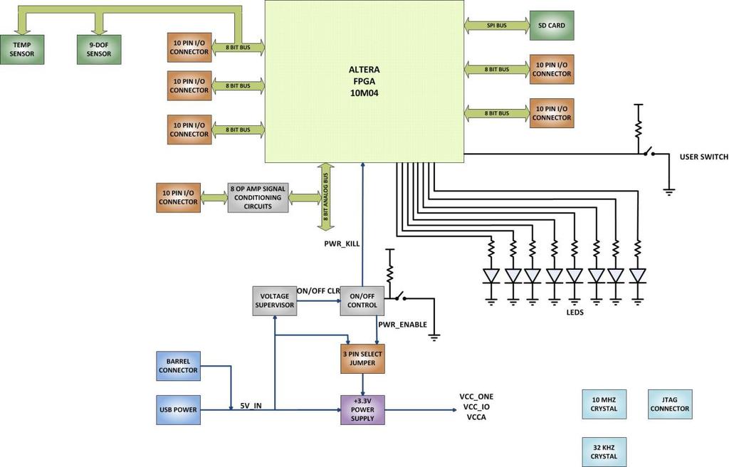
2 easily scalable from the entry level college student to the most advanced projects like an audio sound meter with FFT. Upon the many great features of the MaxProLogic is the MAX10 chip has a built in Flash for configuration and incorporates 8 channels of Analog to Digital Conversion. These two features alone create a far superior FPGA chip than any competitor on the market. It allows the user to create more diverse projects. MAX 10 10M04SA FPGA FROM INTEL/ALTERA 4,000 Logic Elements; 2.2 Mbit On chip Flash; 189 Kbit On Chip SRAM 8 Analog Input Channels; 12 bit; 1MSamples/Second 65 Available I/O s at connectors 8 Green User configurable LEDs 1 Power Pushbutton Switch; 1 User Configurable Pushbutton Switch On Board SD Card Slot Two Power options: Standard USB 2Amp) Using Micro-B connector; 5mm Barrel Connector Accepts 3Amp Switching Power Supply, Provides stable output under high load stress Two Clocks: 50MHz Oscillator; KHz Oscillator On board interface to Standard USB to Serial Adapters 1 Block Diagram Figure 1 MaxProLogic Component Location Page 2

3 Figure 2 EPT-4CE6-AF Block Diagram Page 3
4 Page 4

5 2 Mechanical Dimensions 3 Pin Mapping Figure 4. Pin Mapping between Arduino Due, DueProLogic and FPGA User code Connector-Pin # Net MAX10 Pin J3-1 XIO3_0 88 XIO3[0] J3-2 XIO3_1 89 XIO3[1] J3-3 XIO3_2 90 XIO3[2] J3-4 XIO3_3 91 XIO3[3] Page 5
6 J3-5 XIO3_4 96 XIO3[4] J3-6 XIO3_5 98 XIO3[5] J3-7 XIO3_6 80 XIO3[6] J3-8 XIO3_7 97 XIO3[7] J3-9 GND NC NC J3-10 GND NC NC Connector-Pin # Net MAX10 Pin J4-1 COMMS_TX 92 XIO8[0] J4-2 COMMS_RX 93 XIO8[1] J4-3 XIO8_2 99 XIO8[2] J4-4 XIO8_3 100 XIO8[3] J4-5 XIO8_4 101 XIO8[4] J4-6 XIO8_5 102 XIO8[5] J4-7 XIO8_6 105 XIO8[6] J4-8 XIO8_7 106 XIO8[7] J4-9 GND NC NC J4-10 GND NC NC Connector-Pin # Net MAX10 Pin J5-1 5V_IN NC XIO4[0] J5-2 3V3 NC XIO4[1] Page 6
7 J5-3 XIO4_0 41 XIO4[2] J5-4 XIO4_1 43 XIO4[3] J5-5 XIO4_2 44 XIO4[4] J5-6 XIO4_3 45 XIO4[5] J5-7 XIO4_4 46 XIO4[6] J5-8 XIO4_5 47 XIO4[7] J5-9 GND NC NC J5-10 GND NC NC Connector-Pin # Net MAX10 Pin J6-1 SD_DAT0 48 XIO1[0] J6-2 SD_DAT1 61 XIO1[1] J6-3 XIO1_2 62 XIO1[2] J6-4 XIO1_3 64 XIO1[3] J6-5 XIO1_4 65 XIO1[4] J6-6 XIO1_5 66 XIO1[5] J6-7 XIO1_6 69 XIO1 [6] J6-8 XIO1_7 70 XIO1[7] J6-9 GND NC NC J6-10 GND NC NC Connector-Pin # Net MAX10 Pin Page 7
8 J7-1 XIO5_0 50 XIO5[0] J7-2 XIO5_1 52 XIO5[1] J7-3 XIO5_2 54 XIO5[2] J7-4 XIO5_3 55 XIO5[3] J7-5 XIO5_4 56 XIO5[4] J7-6 XIO5_5 57 XIO5[5] J7-7 XIO5_6 58 XIO5[6] J7-8 XIO5_7 59 XIO5[7] J7-9 GND NC NC J7-10 GND NC NC Connector-Pin # Net MAX10 Pin J8-1 I2C_0_SCL 110 XIO7[0] J8-2 I2C_0_SDA 111 XIO7[1] J8-3 XIO7_2 113 XIO7[2] J8-4 XIO7_3 114 XIO7[3] J8-5 XIO7_4 118 XIO7[4] J8-6 XIO7_5 119 XIO7[5] J8-7 XIO7_6 112 XIO7[6] J8-8 XIO7_7 123 XIO7[7] J8-9 GND NC NC J8-10 GND NC NC Page 8
9 Connector-Pin # Net MAX10 Pin J10-1 XIO6_0 120 XIO6 [1] J10-2 XIO6_1 124 XIO6[1] J10-3 XIO6_2 127 XIO6[2] J10-4 XIO6_3 130 XIO6[3] J10-5 XIO6_4 131 XIO6[4] J10-6 XIO6_5 132 XIO6[5] J10-7 XIO6_6 135 XIO6[6] J10-8 XIO6_7 140 XIO6[7] J10-9 GND NC NC J10-10 GND NC NC Connector-Pin # Net MAX10 Pin J11-1 5V_IN NC NC J11-2 ANALOG_1 6 ANALOG[0] J1-3 ANALOG_2 7 ANALOG[1] J11-4 ANALOG_3 8 ANALOG[2] J11-5 ANALOG_4 10 ANALOG[3] J11-6 ANALOG_5 11 ANALOG[4] J11-7 ANALOG_6 12 ANALOG[5] J11-8 ANALOG_7 13 ANALOG[6] J11-9 ANALOG_8 14 ANALOG[7] Page 9
10 J11-10 GND NC Data Sheet EPT FPGA Development System Connector-Pin # Net MAX10 Pin J12-1 XIO2_0 74 XIO2[0] J12-2 XIO2_1 75 XIO2[1] J12-3 XIO2_2 76 XIO2[2] J12-4 XIO2_3 77 XIO2[3] J12-5 XIO2_4 78 XIO2[4] J12-6 XIO2_5 79 XIO2[5] J12-7 XIO2_6 81 XIO2[6] J12-8 XIO2_7 84 XIO2[7] J12-9 XIO2_8 85 XIO2[8] J12-10 XIO2_9 86 XIO2[9] 4 Pushbutton switches There are two pushbutton switches on the MaxProLogic. Both are momentary contact switches. They include a 1uF cap to ground to debounce both switches. 5 LEDs There are 8 total LEDs on the MaxProLogic. All eight are green LEDs. Component Net Pin on FPGA Signal in EPT Project Pinout Page 10
![LED1 LED1 21 LED[0] LED2 LED2 22 LED[1] LED3 LED3 24 LED[2] LED4 LED4 25 LED[3] LED5 LED5 32 LED[4] LED6 LED6 33 LED[5] LED7 LED7 38 LED[6] LED8 LED8 39 LED[7] 6 Inputs/Outputs The MaxProLogic has](/docs-images/79/79866253/images/11-1.jpg "eight 10 pin headers that provide 64 digital Inputs and Outputs. All of the I/O s are +3.3 VDC only. All I/O s connect directly from the FPGA to one of the ten pin headers.")
11 LED1 LED1 21 LED[0] LED2 LED2 22 LED[1] LED3 LED3 24 LED[2] LED4 LED4 25 LED[3] LED5 LED5 32 LED[4] LED6 LED6 33 LED[5] LED7 LED7 38 LED[6] LED8 LED8 39 LED[7] 6 Inputs/Outputs The MaxProLogic has eight 10 pin headers that provide 64 digital Inputs and Outputs. All of the I/O s are +3.3 VDC only. All I/O s connect directly from the FPGA to one of the ten pin headers. All I/O s are organized into separate banks of the FPGA. There are eight banks. These different banks provide different output speed technologies. Programmable Open Drain The optional open-drain output for each I/O pin is equivalent to an open collector output. If it is configured as an open drain, the logic value of the output is either high-z or logic low. Use an external resistor to pull the signal to a logic high. Programmable Bus Hold Each I/O pin provides an optional bus-hold feature that is active only after configuration. When the device enters user mode, the bus-hold circuit captures the value that is present Page 11

12 on the pin by the end of the configuration. The bus-hold circuitry holds this pin state until the next input signal is present. Because of this, you do not require an external pull-up or pull-down resistor to hold a signal level when the bus is tri-stated. For each I/O pin, you can individually specify that the bus-hold circuitry pulls non-driven pins away from the input threshold voltage where noise can cause unintended high-frequency switching. To prevent over-driving signals, the bus-hold circuitry drives the voltage level of the I/O pin lower than the VCCIO level. If you enable the bus-hold feature, you cannot use the programmable pull-up option. To configure the I/O pin for differential signals, disable the bushold feature. Programmable Pull-Up Resistor Each I/O pin provides an optional programmable pull-up resistor during user mode. The pull-up resistor weakly holds the I/O to the VCCIO level. If you enable the weak pull-up resistor, you cannot use the bus-hold feature. Programmable Current Strength You can use the programmable current strength to mitigate the effects of high signal attenuation that is caused by a long transmission line or a legacy backplane. 7 FPGA Configuration The MaxProLogic has an internal Flash. This flash is used to configure the FPGA. The has a 5x2 header for use in programming the MAX10 FPGA via JTAG. The connector is located in the bottom right corner of the MaxProLogic. It is shrouded and keyed to allow easier insertion. This connector uses the standard Altera Blaster connector pinout. Page 12

13 8 Communications Interface The MaxProLogic is equipped with a communications port that is compatible with FTDI Breakout Boards. It is a 6 pin female header that connects directly with most Breakout boards. The pinout: Communications Pin # Signal 1 NC 2 RX 3 TX 4 VCC 5 NX 6 GND Page 13

14 The Communications Connector provides a path between the FTDI Breakout Board and the MAX10 FPGA. It brings both the RX and TX signals into the FPGA at the following pins. FPGA Pin # Signal 92 RX 93 TX 9 MaxProLogic Power Core Board Power Budget Device Part +1.2V Power +2.5V Power +3.3V Power FPGA 10M04SAE144C8??? Defined by user code. EPT-Transfer- Demo code: 50mA 10mA??? Defined by user code.. EPT- Transfer- Demo code: 50mA Page 14
15 On/Off Controller Temperature Chip 50MHz Oscillator KHz Oscillator Op-Amp driver User LEDs MAX1605 TMP100 FXO-HC536R-66 FXO-HC536R- 100 MCP6L04 47 ma 47 ma 0.5 ma (all four amps active) 20 ma Total 50mA 10mA 261mA *Theoritical Values only. This data needs to be validated Page 15
EARTH PEOPLE TECHNOLOGY, Inc. MAXPROLOGIC DEVELOPMENT SYSTEM User Manual
 EARTH PEOPLE TECHNOLOGY, Inc MAXPROLOGIC DEVELOPMENT SYSTEM User Manual The MaxProLogic is an FPGA development board that is designed to be user friendly and a great introduction into digital design for
UnoMax CPLD Development System. Data Sheet
 UnoMax CPLD Development System Data Sheet The UnoMax is a small form factor CPLD Development System. The core functions of the UnoMax are a two channel USB to Serial chip, 570 Logic Cell CPLD and a four
Altera EP4CE6 Mini Board. Hardware User's Guide
 Altera Hardware User's Guide 1. Introduction Thank you for choosing the! is a compact FPGA board which is designed based on device. It's a low-cost and easy-to-use platform for learning Altera's Cyclone
EARTH PEOPLE TECHNOLOGY, Inc. MAXPROLOGIC DEVELOPMENT SYSTEM User Manual
 EARTH PEOPLE TECHNOLOGY, Inc MAXPROLOGIC DEVELOPMENT SYSTEM User Manual The MaxProLogic is an FPGA development board that is designed to be user friendly and a great introduction into digital design for
FPGA Discovery-III XC3S200 Board Manual
 FPGA Discovery-III XC3S200 Board Manual 77/9 SOI LADPRAO 1, LADPRAO ROAD, JOMPOL, JATUJAK DISTRICT, BANGKOK THAILAND 10900 TEL. 66(0)2939-2084 FAX.66(0)2939-2084 http://www.ailogictechnology.com 1 FPGA
EARTH PEOPLE TECHNOLOGY. ODIN-LINK BLE + MAXPROLOGIC Development System User Manual
 EARTH PEOPLE TECHNOLOGY ODIN-LINK BLE + MAXPROLOGIC Development System User Manual This User Manual covers the Odin-Link and MaxProLogic Development System. The Odin-Link board includes the Texas Instruments
Xynergy XS Motherboard Rev3 Documentation April 24, 2012
 Topic Page Overview 1 DIMM Socket 1 Power Supply 2 I/O Voltage Selection 3 I/O Connectors 3,4 I2C/SMBUS 5 RS232 5 Testing I/Os 6 SD-Card 6 USB2.0 OTG 7 Ethernet Interface 7 CAN Interfaces 8 JTAG Interfaces
EPT-200TMP-TS-U2 TMP102 Temperature Sensor Docking Board Data Sheet
 EPT-2TMP-TS-U2 TMP12 Temperature Sensor Docking Board Data Sheet This docking board is based on the TMP12 Temperature Sensor chip from Texas Instruments. It can measure the ambient temperature between
ONYX-MM-XT PC/104 Format Counter/Timer & Digital I/O Module
 ONYX-MM-XT PC/104 Format Counter/Timer & Digital I/O Module User Manual V1.4 Copyright 2009 Diamond Systems Corporation 1255 Terra Bella Avenue Mountain View, CA 94043 USA Tel (650) 810-2500 Fax (650)
ILI2312. ILI2312 Single Chip Capacitive Touch Sensor Controller. Specification ILI TECHNOLOGY CORP. Version: V1.03.
 Single Chip Capacitive Touch Sensor Controller Specification Version: V1.03 Date: 2015/11/17 ILI TECHNOLOGY CORP. 8F, No.38, Taiyuan St., Jhubei City, Hsinchu County 302, Taiwan, R.O.C. Tel.886-3-5600099;
DEMO9S08SH8/SG8 Demonstration Board for Freescale MC9S08SH8/SG8
 DOC-0398-010, REV A DEMO9S08SH8/SG8 Demonstration Board for Freescale MC9S08SH8/SG8 Axiom Manufacturing 2813 Industrial Lane Garland, TX 75041 Email: Sales@axman.com Web: http://www.axman.com CONTENTS
CHAPTER 1 Introduction of the tnano Board CHAPTER 2 tnano Board Architecture CHAPTER 3 Using the tnano Board... 8
 CONTENTS CHAPTER 1 Introduction of the tnano Board... 2 1.1 Features...2 1.2 About the KIT...4 1.3 Getting Help...4 CHAPTER 2 tnano Board Architecture... 5 2.1 Layout and Components...5 2.2 Block Diagram
ET-UARTSWD Users Guide
 User s Guide ET-UARTSWD Users Guide Power Application Controller s www.active-semi.com Copyright 2018 Active-Semi, Inc. CONTENTS Contents...2 Overview...3 1. ET-UARTSWD Resources...6 1.1 Provided Connectors...6
DEMO9S08SH32/SG32 Demonstration Board for Freescale MC9S08SH32/SG32
 DOC-0421-010, REV A DEMO9S08SH32/SG32 Demonstration Board for Freescale MC9S08SH32/SG32 Axiom Manufacturing 2813 Industrial Lane Garland, TX 75041 Email: Sales@axman.com Web: http://www.axman.com CONTENTS
ILI2511. ILI2511 Single Chip Capacitive Touch Sensor Controller. Specification ILI TECHNOLOGY CORP. Version: V1.4. Date: 2018/7/5
 Single Chip Capacitive Touch Sensor Controller Specification Version: V1.4 Date: 2018/7/5 ILI TECHNOLOGY CORP. 8F., No.1, Taiyuan 2 nd St., Zhubei City, Hsinchu County 302, Taiwan (R.O.C.) Tel.886-3-5600099;
ADDJOG User Guide 7/30/10. Overview
 ADDJOG User Guide 7/30/10 Overview The ADDJOG is a PLC expansion board used to add digital inputs and outputs to a compatible host PLC. The ADDJOG has 64 open collector outputs and 64 non-isolated inputs.
Mega128-DEVelopment Board Progressive Resources LLC 4105 Vincennes Road Indianapolis, IN (317) (317) FAX
 (317) FAX") Mega128-DEVelopment Board Progressive Resources LLC 4105 Vincennes Road Indianapolis, IN 46268 (317) 471-1577 (317) 471-1580 FAX http://www.prllc.com GENERAL The Mega128-Development board is designed for
Mega128-DEVelopment Board Progressive Resources LLC 4105 Vincennes Road Indianapolis, IN 46268 (317) 471-1577 (317) 471-1580 FAX http://www.prllc.com GENERAL The Mega128-Development board is designed for
4. Configuring Cyclone II Devices
 4. Configuring Cyclone II Devices CII51013-2.0 Introduction Cyclone II devices use SRAM cells to store configuration data. Since SRAM memory is volatile, configuration data must be downloaded to Cyclone
Mercury Baseboard Reference Manual
 Mercury Baseboard Reference Manual www.micro-nova.com OVERVIEW The Baseboard is a great addition to the Mercury Module, providing a host of on-board components that can be used to design and test a wide
Click-A-Tune. User Manual
 Contents Configuring the...2 Transferring data to the...2 with switch configuration...3 with switch matrix up to 3 switches...4 Changing the playback volume...5 Connections... Power requirements (Vin)...
5. Configuring Cyclone FPGAs
 5. Configuring Cyclone FPGAs C51013-1.5 Introduction You can configure Cyclone TM FPGAs using one of several configuration schemes, including the active serial (AS) configuration scheme. This scheme is
RS232/TTL Modem Interface Data Sheet Product Specifications and Performance
 www.rfdesign.com.au RS232/TTL Modem Interface Data Sheet Product Specifications and Performance *Modem not included Features RS232/TTL translation DB9 female serial port connector Selectable external power
Adafruit USB Power Gauge Mini-Kit
 Adafruit USB Power Gauge Mini-Kit Created by Bill Earl Last updated on 2017-07-14 11:55:04 PM UTC Guide Contents Guide Contents Overview Assembly Basic Assembly Solder the female connector. Solder the
Genesys Logic, Inc. GL827L. USB 2.0 Single Slot SD/MMC/MS Card Reader Controller. Datasheet
 Genesys Logic, Inc. GL827L USB 2.0 Single Slot SD/MMC/MS Card Reader Controller Datasheet Revision 1.03 Oct. 17, 2008 Copyright: Copyright 2008 Genesys Logic Incorporated. All rights reserved. No part
Sidewinder Development Board rev 1.0
 33 Sidewinder Development Board rev 1.0 Features Altera MAX V CPLD 5M160ZT100C5 JTAG programmable USB programmable USB powered 12 On board LEDs 10 on board switches 3 RGB LEDs One 40 pin expansion headers
Wi125 Evaluation Kit User Manual
 Wi125 Evaluation Kit User Manual Issue: R01 Available at Digi-Key www.digikey.com Bulletin SG172-DKUM Revision R01 Date 06 May 2010 Table of Contents 1. Introduction 3 2. Wi125 Evaluation Board Overview
ECE 480 Team 5 Introduction to MAVRK module
 ECE 480 Team 5 Introduction to MAVRK module Team Members Jordan Bennett Kyle Schultz Min Jae Lee Kevin Yeh Definition of MAVRK Component of MAVRK starter Kit Component of umavrk Module design procedure
DEVBOARD3 DATASHEET. 10Mbits Ethernet & SD card Development Board PIC18F67J60 MICROCHIP
 DEVBOARD3 DATASHEET 10Mbits Ethernet & SD card PIC18F67J60 MICROCHIP Version 1.0 - March 2009 DEVBOARD3 Version 1.0 March 2009 Page 1 of 7 The DEVBOARD3 is a proto-typing board used to quickly and easily
ootbrobotics.com Electronics and Robotics LLC
 2 Warning Before Proceeding... 4 On Board Features... 5 Smart Power Switching... 5 Indicators... 5 Power Indicators... 5 Status LED... 5 RGB Indicator... 5 External Power (EXP) Indicator... 6 USB Serial
Propeller Activity Board (#32910)
") Web Site: www.parallax.com Forums: forums.parallax.com Sales: sales@parallax.com Technical: support@parallax.com Office: (916) 624-8333 Fax: (916) 624-8003 Sales: (888) 512-1024 Tech Support: (888) 997-8267
Web Site: www.parallax.com Forums: forums.parallax.com Sales: sales@parallax.com Technical: support@parallax.com Office: (916) 624-8333 Fax: (916) 624-8003 Sales: (888) 512-1024 Tech Support: (888) 997-8267
ARDUINO LEONARDO WITH HEADERS Code: A000057
 ARDUINO LEONARDO WITH HEADERS Code: A000057 Similar to an Arduino UNO, can be recognized by computer as a mouse or keyboard. The Arduino Leonardo is a microcontroller board based on the ATmega32u4 (datasheet).
Digital Discovery Reference Manual
 Digital Discovery Reference Manual The Digilent Digital Discovery is a combined logic analyzer and pattern generator instrument that was created to be the ultimate embedded development companion. The Digital
5I20 ANYTHING I/O MANUAL
 5I20 ANYTHING I/O MANUAL Version 1.9 This page intentionally not blank 12 24 LOOPBACK Table of Contents GENERAL.......................................................... 1 DESCRIPTION.................................................
8:1 Serial Port Expander
 8:1 Serial Port Expander V 1.3 This is an evolving document check back for updates. Features Expand a single UART (RX / TX) serial port into 8 additional serial ports On-board LEDs indicate which channel
ARDUINO YÚN Code: A000008
 ARDUINO YÚN Code: A000008 Arduino YÚN is the perfect board to use when designing connected devices and, more in general, Internet of Things projects. It combines the power of Linux with the ease of use
PAC5523EVK1. Power Application Controllers. PAC5523EVK1 User s Guide. Copyright 2017 Active-Semi, Inc.
 PAC5523EVK1 Power Application Controllers PAC5523EVK1 User s Guide www.active-semi.com Copyright 2017 Active-Semi, Inc. CONTENTS Contents...2 Overview...3 PAC5523EVK1 Resources...5 Pinout and Signal Connectivity...5
icex-cmtm General specs and Installation guide
 icex-cmtm General specs and Installation guide 1. General view 2. Specifications 2.1. Common specs: Ethernet 1 x 10/100Base/T, RJ45 connector with traffic and link LED Serial Interface 1 x RS232/485 USB
HomeVision-Pro Overview for HomeVision Users
 HomeVision-Pro Overview for HomeVision Users This document has two main purposes: 1. To describe the main differences between HomeVision and HomeVision-Pro. 2. To assist HomeVision users in converting
Part Number: PCB-STM32-F4B1 (unpopulated PCB with Discovery module sockets, no other parts) STM32-F4B1 (assembled board, not presently available)
 STM32-F4B1 (assembled board, not presently available)") PCB-STM32-F4B1 Development baseboard for the STMicro Discovery-F4 module (STMicro part# STM32F4DISCOVERY) PCB Rev 1.00 shown. PCB Rev 1.20 has on-board RS232 drivers. Part Number: PCB-STM32-F4B1 (unpopulated
PCB-STM32-F4B1 Development baseboard for the STMicro Discovery-F4 module (STMicro part# STM32F4DISCOVERY) PCB Rev 1.00 shown. PCB Rev 1.20 has on-board RS232 drivers. Part Number: PCB-STM32-F4B1 (unpopulated
4I39 RS-422 ANYTHING I/O MANUAL
 4I39 RS-422 ANYTHING I/O MANUAL V1.0 Table of Contents GENERAL.......................................................... 1 DESCRIPTION................................................. 1 HARDWARE CONFIGURATION........................................
PRELAB! Read the entire lab, and complete the prelab questions (Q1- Q3) on the answer sheet before coming to the laboratory.
 on the answer sheet before coming to the laboratory.") PRELAB! Read the entire lab, and complete the prelab questions (Q1- Q3) on the answer sheet before coming to the laboratory. 1.0 Objectives In this lab you will get familiar with the concept of using the
PRELAB! Read the entire lab, and complete the prelab questions (Q1- Q3) on the answer sheet before coming to the laboratory. 1.0 Objectives In this lab you will get familiar with the concept of using the
DS1676 Total Elapsed Time Recorder, Erasable
 www.dalsemi.com Preliminary DS1676 Total Elapsed Time Recorder, Erasable FEATURES Records the total time that the Event Input has been active and the number of events that have occurred. Volatile Elapsed
Goal: We want to build an autonomous vehicle (robot)
") Goal: We want to build an autonomous vehicle (robot) This means it will have to think for itself, its going to need a brain Our robot s brain will be a tiny computer called a microcontroller Specifically
Goal: We want to build an autonomous vehicle (robot) This means it will have to think for itself, its going to need a brain Our robot s brain will be a tiny computer called a microcontroller Specifically
ARDUINO LEONARDO ETH Code: A000022
 ARDUINO LEONARDO ETH Code: A000022 All the fun of a Leonardo, plus an Ethernet port to extend your project to the IoT world. You can control sensors and actuators via the internet as a client or server.
EZ-Bv4 Datasheet v0.7
 EZ-Bv4 Datasheet v0.7 Table of Contents Introduction... 2 Electrical Characteristics... 3 Regulated and Unregulated Power Pins... 4 Low Battery Warning... 4 Hardware Features Main CPU... 5 Fuse Protection...
CDN503 HIGH DENSITY I/O ADAPTER USER GUIDE
 CDN503 HIGH DENSITY I/O ADAPTER USER GUIDE 13050301 (c) Copyright DIP Inc., 1996 DIP Inc. P.O. Box 9550 MORENO VALLEY, CA 92303 714-924-1730 CONTENTS DN503 PRODUCT OVERVIEW 1 DN503 INSTALLATION 1 POWER
Kinetis K70 System-On-Module (SOM) Baseboard Hardware Architecture
 Baseboard Hardware Architecture") Kinetis K70 System-On-Module (SOM) Baseboard Version 1.0 Table of Contents 1. OVERVIEW...3 2. REFERENCES...3 3. HARDWARE PLATFORM...3 3.1. OVERVIEW...3 3.2. FUNCTIONAL BLOCK DIAGRAM...4 3.3. SOM CONNECTORS...4
Kinetis K70 System-On-Module (SOM) Baseboard Version 1.0 Table of Contents 1. OVERVIEW...3 2. REFERENCES...3 3. HARDWARE PLATFORM...3 3.1. OVERVIEW...3 3.2. FUNCTIONAL BLOCK DIAGRAM...4 3.3. SOM CONNECTORS...4
Arduino Uno R3 INTRODUCTION
 Arduino Uno R3 INTRODUCTION Arduino is used for building different types of electronic circuits easily using of both a physical programmable circuit board usually microcontroller and piece of code running
ARDUINO UNO REV3 SMD Code: A The board everybody gets started with, based on the ATmega328 (SMD).
.") ARDUINO UNO REV3 SMD Code: A000073 The board everybody gets started with, based on the ATmega328 (SMD). The Arduino Uno SMD R3 is a microcontroller board based on the ATmega328. It has 14 digital input/output
ARDUINO UNO REV3 SMD Code: A000073 The board everybody gets started with, based on the ATmega328 (SMD). The Arduino Uno SMD R3 is a microcontroller board based on the ATmega328. It has 14 digital input/output
GWBMA0x Bluetooth Audio module
 GWBMA0x Bluetooth Audio module Data sheet version 0.9 draft GWBMA0X DATASHEET 0.9 GIGAWIT 1 Introduction GWBMA1X is a high performance Bluetooth audio module, It provides various type of wireless audio
PVK40. User's manual. Feature Rich Development and Educational Kit for 40-pin Microchip PIC microcontrollers
 PVK40 User's manual Feature Rich Development and Educational Kit for 40-pin Microchip PIC microcontrollers CONTENTS PVK40 3 On-board peripherals: 3 Power supply 4 Microcontroller 4 Reset circuitry 4 Oscilator
Wireless Sensor Networks. FireFly 2.2 Datasheet
 2.2 Datasheet July 6, 2010 This page intentionally left blank. Contents 1. INTRODUCTION...1 Features...1 Applications...2 2. BLOCK DIAGRAM...3 3. HARDWARE CONNECTIONS...4 Power...5 Header 1 ( UARTS, I2C,
CONTENTS BIGAVR2 KEY FEATURES 4 CONNECTING THE SYSTEM 5 INTRODUCTION 6
 CONTENTS BIGAVR2 KEY FEATURES 4 CONNECTING THE SYSTEM 5 INTRODUCTION 6 Switches 7 Jumpers 8 MCU Sockets 9 Power Supply 11 On-board USB 2.0 Programmer 12 Oscillator 14 LEDs 15 Reset Circuit 17 Push-buttons
Hollybush1 User Manual. Issue 1.00
 Hollybush1 User Manual Issue 1.00 Kit Contents You should receive the following items with you Hollybush1 development kit: 1 - Hollybush1 Board, 2 PROG2 Programming Cable (not with OEM). Foreword PLEASE
MegaAVR-DEVelopment Board Progressive Resources LLC 4105 Vincennes Road Indianapolis, IN (317) (317) FAX
 (317) FAX") MegaAVR-DEVelopment Board Progressive Resources LLC 4105 Vincennes Road Indianapolis, IN 46268 (317) 471-1577 (317) 471-1580 FAX http://www.prllc.com GENERAL The MegaAVR-Development board is designed for
MegaAVR-DEVelopment Board Progressive Resources LLC 4105 Vincennes Road Indianapolis, IN 46268 (317) 471-1577 (317) 471-1580 FAX http://www.prllc.com GENERAL The MegaAVR-Development board is designed for
ARDUINO MICRO WITHOUT HEADERS Code: A000093
 ARDUINO MICRO WITHOUT HEADERS Code: A000093 Arduino Micro is the smallest board of the family, easy to integrate it in everyday objects to make them interactive. The Micro is based on the ATmega32U4 microcontroller
P&E Microcomputer Systems, Inc. P.O. Box 2044, Woburn, MA 01888, USA
 P&E Microcomputer Systems, Inc. P.O. Box 2044, Woburn, MA 01888, USA TEL: (617) 353-9206 FAX: (617) 353-9205 http://www.pemicro.com USB-ML-MON08 Rev D Technical Summary Document # PE3357, Version 1.01
Preliminary. PACKAGE - 28-pin MLP (5mm X 5mm) Example Circuit Diagram CP V. 48MHz Oscillator. USB Function Controller 512B EEPROM
 Example Circuit Diagram CP V. 48MHz Oscillator. USB Function Controller 512B EEPROM") Preliminary Single-Chip USB to UART Bridge SINGLE-CHIP USB to UART DATA TRANSFER - Integrated USB Transceiver; No External Resistors Required - Integrated Clock; No External Crystal Required - Integrated
Preliminary Single-Chip USB to UART Bridge SINGLE-CHIP USB to UART DATA TRANSFER - Integrated USB Transceiver; No External Resistors Required - Integrated Clock; No External Crystal Required - Integrated
ISDN OEM1. DesignGuide V1.2
 ISDN OEM1 DesignGuide V1.2 Content ISDN OEM1...1 1 Objective...3 2 Product description...3 3 Software interfaces...4 3.1 Dialing procedures...4 3.2 AT commands...4 3.2.1 Configuration commands...4 3.2.2
ARDUINO INDUSTRIAL 1 01 Code: A000126
 ARDUINO INDUSTRIAL 1 01 Code: A000126 The Industrial 101 is a small form-factor YUN designed for product integration. OVERVIEW: Arduino Industrial 101 is an Evaluation board for Arduino 101 LGA module.
ACR8000 Hardware Manual
 p/n YPM08119 Automation ACR8000 Hardware Manual Effective: October 7, 2002 This page intentionally left blank. ACR8000 Hardware Manual P/N PM08119 Version Change: From: Version 1.02, Dated 7/8/1999 To:
Revision: 5/7/ E Main Suite D Pullman, WA (509) Voice and Fax. Power jack 5-9VDC. Serial Port. Parallel Port
 Voice and Fax. Power jack 5-9VDC. Serial Port. Parallel Port") Digilent Digilab 2 Reference Manual www.digilentinc.com Revision: 5/7/02 215 E Main Suite D Pullman, WA 99163 (509) 334 6306 Voice and Fax Overview The Digilab 2 development board (the D2) features the
Digilent Digilab 2 Reference Manual www.digilentinc.com Revision: 5/7/02 215 E Main Suite D Pullman, WA 99163 (509) 334 6306 Voice and Fax Overview The Digilab 2 development board (the D2) features the
BeMicro Max 10 FPGA Evaluation Kit
 BeMicro Max 10 FPGA Evaluation Kit Getting Started User Guide Version 14.0.2 11/24/2014 User Guide Table of Contents 1. OVERVIEW...2 1.1 Board Features... 2 1.2 Block Diagram... 3 1.3 Getting To Know Your
Digilab 2E Reference Manual
 Digilent 2E System Board Reference Manual www.digilentinc.com Revision: February 8, 2005 246 East Main Pullman, WA 99163 (509) 334 6306 Voice and Fax Digilab 2E Reference Manual Overview The Digilab 2E
P-ROC. Pinball Remote Operations Controller. Version 2.4 August 8, Copyright 2017, Multimorphic, Inc. 1/28
 P-ROC Pinball Remote Operations Controller Version 2.4 August 8, 2017 Copyright 2017, Multimorphic, Inc. 1/28 Table of Contents 1 Introduction... 3 2 Block Diagram... 4 3 Theory of Operation... 6 4 Functional
Amarjeet Singh. January 30, 2012
 Amarjeet Singh January 30, 2012 Website updated - https://sites.google.com/a/iiitd.ac.in/emsys2012/ Lecture slides, audio from last class Assignment-2 How many of you have already finished it? Final deadline
CF Plug-In. Evaluation Board User Guide. Bulletin Revision Date
 CF Plug-In Evaluation Board User Guide Bulletin Revision Date JA03-EBUG 00 06 Dec 2017 Table of Contents I. Introduction------------------------------------------------------------------------- 2 Scope
Arduino Uno. Arduino Uno R3 Front. Arduino Uno R2 Front
 Arduino Uno Arduino Uno R3 Front Arduino Uno R2 Front Arduino Uno SMD Arduino Uno R3 Back Arduino Uno Front Arduino Uno Back Overview The Arduino Uno is a microcontroller board based on the ATmega328 (datasheet).
Connecting Spansion SPI Serial Flash to Configure Altera FPGAs
 Connecting SPI Serial Flash to Configure Altera s Application By Frank Cirimele 1. Introduction Altera s are programmable logic devices used for basic logic functions, chip-to-chip connectivity, signal
ARDUINO MEGA 2560 REV3 Code: A000067
 ARDUINO MEGA 2560 REV3 Code: A000067 The MEGA 2560 is designed for more complex projects. With 54 digital I/O pins, 16 analog inputs and a larger space for your sketch it is the recommended board for 3D
Embedded Systems and Software
 Embedded Systems and Software Lecture 12 Some Hardware Considerations Hardware Considerations Slide 1 Logic States Digital signals may be in one of three states State 1: High, or 1. Using positive logic
Web Site: Forums: forums.parallax.com Sales: Technical:
 Web Site: www.parallax.com Forums: forums.parallax.com Sales: sales@parallax.com Technical: support@parallax.com Office: (916) 624-8333 Fax: (916) 624-8003 Sales: (888) 512-1024 Tech Support: (888) 997-8267
ARDUINO YÚN MINI Code: A000108
 ARDUINO YÚN MINI Code: A000108 The Arduino Yún Mini is a compact version of the Arduino YUN OVERVIEW: Arduino Yún Mini is a breadboard PCB developed with ATmega 32u4 MCU and QCA MIPS 24K SoC CPU operating
VLSI AppNote: VSx053 Simple DSP Board
 : VSx053 Simple DSP Board Description This document describes the VS1053 / VS8053 Simple DPS Board and the VSx053 Simple DSP Host Board. Schematics, layouts and pinouts of both cards are included. The
ESPino - Specifications
 ESPino - Specifications Summary Microcontroller ESP8266 (32-bit RISC) WiFi 802.11 (station, access point, P2P) Operating Voltage 3.3V Input Voltage 4.4-15V Digital I/O Pins 9 Analog Input Pins 1 (10-bit
Alessandra de Vitis. Arduino
 Alessandra de Vitis Arduino Arduino types Alessandra de Vitis 2 Interfacing Interfacing represents the link between devices that operate with different physical quantities. Interface board or simply or
Section 3. System Integration
 Section 3. System Integration This section includes the following chapters: Chapter 9, Configuration, Design Security, and Remote System Upgrades in the Cyclone III Device Family Chapter 10, Hot-Socketing
Chapter 2 ICB Architecture Chapter 3 Board Components GPIO Interface RS-232 Interface RS-485 Interface...
 1 CONTENTS Chapter 1 Introduction... 3 1.1 Features...3 1.2 About the Kit...4 1.3 Getting Help...5 Chapter 2 ICB Architecture... 6 2.1 Layout and Components...6 2.2 Block Diagram of the ICB...7 Chapter
4. Hot Socketing and Power-On Reset in MAX V Devices
 December 2010 MV51004-1.0 4. Hot Socketing and Power-On Reset in MAX V Devices MV51004-1.0 This chapter provides information about hot-socketing specifications, power-on reset (POR) requirements, and their
Symphony SoundBite Reference Manual
 Symphony SoundBite Reference Manual Document Number: SNDBITERM Rev. 2.0 09/2008 Contents Section 1, Introduction page 2 Section 2, Functional Blocks page 3 Section 3, Configuration and Connections page
Digilab 2 XL Reference Manual
 125 SE High Street Pullman, WA 99163 (509) 334 6306 (Voice and Fax) www.digilentinc.com PRELIMINARY Digilab 2 XL Reference Manual Revision: May 7, 2002 Overview The Digilab 2 XL (D2XL) development board
ARDUINO M0 PRO Code: A000111
 ARDUINO M0 PRO Code: A000111 The Arduino M0 Pro is an Arduino M0 with a step by step debugger With the new Arduino M0 Pro board, the more creative individual will have the potential to create one s most
Propeller Project Board USB (#32810)
") Web Site: www.parallax.com Forums: forums.parallax.com Sales: sales@parallax.com Technical: support@parallax.com Office: (916) 624-8333 Fax: (916) 624-8003 Sales: (888) 512-1024 Tech Support: (888) 997-8267
Web Site: www.parallax.com Forums: forums.parallax.com Sales: sales@parallax.com Technical: support@parallax.com Office: (916) 624-8333 Fax: (916) 624-8003 Sales: (888) 512-1024 Tech Support: (888) 997-8267
BG2D Solderless Connection Gate Drive Prototype Board
 Application NOTES: First Release: May, 2008 BG2D Solderless Connection Gate Drive Prototype Board Description: The BG2D is a two channel gate drive circuit for that the dual NX series modules pins plug
PI2Media 502HTA Hardware Reference Manual P3-8/31/ HTA Hybrid Tube Amp Shield Hardware Reference Manual 2017 PI 2 Design PAGE 1
 502HTA Hybrid Tube Amp Shield Hardware Reference Manual 2017 PI 2 Design PAGE 1 Table of Contents 1 Warranty... 4 2 Operating Specifications... 5 2.1 502HTA Operating specifications... 5 3 Overview...
DS 1682 Total Elapsed Time Recorder with Alarm
 DS 1682 Total Elapsed Time Recorder with Alarm www.dalsemi.com FEATURES Records the total time that the Event Input has been active and the number of events that have occurred. Volatile Elapsed Time Counter
AN-719 APPLICATION NOTE One Technology Way P.O. Box 9106 Norwood, MA Tel: 781/ Fax: 781/
 APPLICATION NOTE One Technology Way P.O. Box 9106 Norwood, MA 02062-9106 Tel: 781/329-4700 Fax: 781/326-8703 www.analog.com ADuC7024 Evaluation Board Reference Guide MicroConverter ADuC7024 Development
ISA Host Controller 15a Hardware Reference Release 1.2 (October 16, 2017)
") ISA Host Controller 15a Hardware Reference 1 ISA Host Controller 15a Hardware Reference Release 1.2 (October 16, 2017) Purpose: Host Controller to support the ISA bus according to the PC/104 specification.
ISA Host Controller 15a Hardware Reference 1 ISA Host Controller 15a Hardware Reference Release 1.2 (October 16, 2017) Purpose: Host Controller to support the ISA bus according to the PC/104 specification.
Nios Embedded Processor Development Board
 Nios Embedded Processor Development Board July 2003, ver. 2.2 Data Sheet Introduction Development Board Features Functional Overview This data sheet describes the features and functionality of the Nios
13. Configuring Stratix & Stratix GX Devices
 13. Configuring Stratix & Stratix GX Devices S52013-2.0 Introduction You can configure Stratix TM and Stratix GX devices using one of several configuration schemes. All configuration schemes use either
CCD VIDEO PROCESSING CHAIN LPF OP AMP. ADS-93x 16 BIT A/D SAMPLE CLAMP TIMING GENERATOR ALTERA 7000S ISP PLD UNIT INT CLOCK MASTER CLOCK
 ADS-93X Timing Generator Board User's Manual Timing Generator Board Description This Timing Generator Board is designed to be part of a two board set, used in conjunction with an ON Semiconductor CCD Imager
CDN502 HIGH DENSITY I/O ADAPTER USER GUIDE
 CDN502 HIGH DENSITY I/O ADAPTER USER GUIDE 13050201 (c) Copyright DIP Inc., 1996 DIP Inc. P.O. Box 9550 MORENO VALLEY, CA 92303 714-924-1730 CONTENTS DN502 PRODUCT OVERVIEW 1 DN502 INSTALLATION 1 POWER
Intel Galileo gen 2 Board
 Intel Galileo gen 2 Board The Arduino Intel Galileo board is a microcontroller board based on the Intel Quark SoC X1000, a 32- bit Intel Pentium -class system on a chip (SoC). It is the first board based
Proposal for SAS 2.x Specification to Enable Support for Active Cables
 08-052r2 Proposal for SAS 2.x Specification to Enable Support for Active Cables Gourgen Oganessyan QUELLAN March 7, 2008 Introduction Inclusion of active cable interconnect option into the SAS specification
LAMPIRAN I (LISTING PROGRAM)
") LAMPIRAN I (LISTING PROGRAM) #include LiquidCrystal lcd(8, 9, 4, 5, 6, 7); const int numreadings = 10; int readings[numreadings]; // the readings from the analog input int readindex =
LAMPIRAN I (LISTING PROGRAM) #include LiquidCrystal lcd(8, 9, 4, 5, 6, 7); const int numreadings = 10; int readings[numreadings]; // the readings from the analog input int readindex =
eip-24/100 Embedded TCP/IP 10/100-BaseT Network Module Features Description Applications
 Embedded TCP/IP 10/100-BaseT Network Module Features 16-bit Microcontroller with Enhanced Flash program memory and static RAM data memory On board 10/100Mbps Ethernet controller, and RJ45 jack for network
Microcontroller. BV523 32bit Microcontroller. Product specification. Jun 2011 V0.a. ByVac Page 1 of 8
 32bit Product specification Jun 2011 V0.a ByVac Page 1 of 8 Contents 1. Introduction...3 2. Features...3 3. Physical Specification...3 3.1. PIC32...3 3.2. USB Interface...3 3.3. Power Supply...4 3.4. Power
Adafruit Metro Mini. Created by lady ada. Last updated on :12:28 PM UTC
 Adafruit Metro Mini Created by lady ada Last updated on 2018-01-24 08:12:28 PM UTC Guide Contents Guide Contents Overview Pinouts USB & Serial converter Microcontroller & Crystal LEDs Power Pins & Regulators
Polmaddie6 User Manual. Issue 1.0
 Polmaddie6 User Manual Issue 1.0 2 Foreword PLEASE READ THIS ENTIRE MANUAL BEFORE PLUGGING IN OR POWERING UP YOUR POLMADDIE6 BOARD. PLEASE TAKE SPECIAL NOTE OF THE WARNINGS WITHIN THIS MANUAL. Trademarks
Intel Stratix 10 General Purpose I/O User Guide
 Intel Stratix 10 General Purpose I/O User Guide Updated for Intel Quartus Prime Design Suite: 18.0 Subscribe Send Feedback Latest document on the web: PDF HTML Contents Contents 1. Intel Stratix 10 I/O