Improved Circuit Reliability/Robustness. Carey Robertson Product Marketing Director Mentor Graphics Corporation
|
|
|
- Corey Bell
- 6 years ago
- Views:
Transcription

1 Improved Circuit Reliability/Robustness Carey Robertson Product Marketing Director Mentor Graphics Corporation


 IP providers.")
2 Reliability Requirements are Growing in all Market Segments Transportation Mobile / Wireless Exhaustive specs/testing for reliability Chips need to be robust against a number of extreme environmental factors Stable platform for 10+ years Pushing the limits of low power, performance and functionality Smaller nodes => smaller oxides Heterogeneous on-chip content drives higher probability of latch-up, cross-power domain issues 2 General CPU / Server Farms Aggressively pursuing smallest process node, performance and functionality.. Design complexity very high. Often an SoC with many (internal) IP providers. Higher probability of latch-up, cross-power domain issues

3 Limitations of Traditional Verification Circuit Failure due to Electrical Overstress (EOS) Thinner-oxide lower voltage less power Some power domain design errors lead to oxide breakdown and failure over time. NBTI (PMOS), HCI (NMOS), SBD Complex Management of bulk and power pins IP blocks may have internal global signals EOS Example LVS: Schematic Matches Layout Schematic Correct Simulation: Static Timing Circuit Simulation X? X X 3


4 ESD Design Rules Electrostatic discharge (ESD) causes severe damage to ICs Several protection schemes have been proposed to mitigate this damage vdd PAD vss Checking for proper ESD protection circuits is needed for reliable design 4


5 A Reliability Verification Platform Calibre PERC provides a robust platform for circuit reliability verification Not just a point tool solution A system view of how design elements interact is needed Used throughout the design flow: schematic, layout, final verification Typical application areas ESD EOS Voltage-aware DRC Low/Multi-power designs Latch-up Understand IC layout impacts on device performance ESD EOS Voltage Aware DRC m3 Design Methodology Low Power m4 dummy dummy m2 m2 m1 m1 dummy dummy 5
")

6 ESD Verification Device and Cell Based Verifications Topological and Layout based checks Reference cell names Verify signals crossing multiple power domains Addresses reliability concerns / EOS Layout centric verification with P2P, CD and DRC Logic Driven Layout (LDL) User defined checks and feedback avdd Pad IO Pad ESD Diode Cell Pin VDD Up Diode ESD Cell Down Diode ESD Cell VSS Inner Gate Cell Current density simulation vss Driver Cell z b a ESD Diode Cell a b z Receiver Cell dvdd vss VSS ESD Cell Pin Ground Port P2P resistance simulation 6


7 Understanding EOS without Simulation Voltage Propagation EOS has historically been one of the leading causes of integrated circuit failures, regardless of the semiconductor manufacturer The result of an EOS event can range from no damage or degradation to the IC up to catastrophic damage where the IC is permanently non-functional Identify design Label voltages Propagate voltages Catch static violations 0 Debug using RVE 7


8 Power Domain Checking Multi-power verification requires system knowledge VDD1 B Z VDD2 Tracking of large numbers of domains GND1 Gate1 Z A Level Shifter A Gate2 GND2 PERC identifies power regions Verifies appropriate level-shifting circuitry 8


9 Post-Layout Verification Topology-based Geometrical Checking 1 Search for the topology 2 Perform the geometrical measurement 3 Compare vs. a constraint & issue violations Constraint Violation: od_ext1 od_ext2 od_ext < 0.1μm 9
10 Partnering with TSMC 10


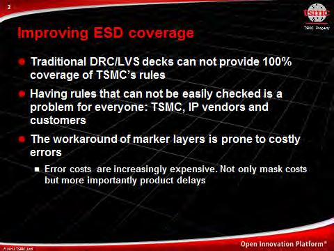
11 Reliability Rules Are Complex ESD/Latch-up Rules 35% of ESD and latch-up rules un-checkable with standard EDA tools The other 65% of rules need additional manually-placed marker layers 11

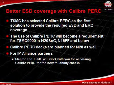
12 TSMC9000 with Calibre PERC Focus on three categories of rules Example checks shown, final determination underway Analog IP here, includes Interface IP, mixed signal, etc. Other categories explored with additional IP 12


13 Industry Support Customer Adoption/Industry Validation 13 Winner of the Customers Choice Award at TSMC s 2011 Open Innovation Platform Ecosystem Forum Electronic Products Magazine 2009 Product of the Year

14 THANK YOU!
Reduce Verification Complexity In Low/Multi-Power Designs. Matthew Hogan, Mentor Graphics
 Reduce Verification Complexity In Low/Multi-Power Designs. Matthew Hogan, Mentor Graphics BACKGROUND The increasing demand for highly reliable products covers many industries, all process nodes, and almost
Latch-up Verification / Rule Checking Throughout Circuit Design Flow
 Latch-up Verification / Rule Checking Throughout Circuit Design Flow Michael Khazhinsky ESD and Latch-up Design Silicon Labs April 2016 Motivation The verification of latch-up protection networks in modern
Improve Reliability With Accurate Voltage-Aware DRC. Matthew Hogan, Mentor Graphics
 Improve Reliability With Accurate Voltage-Aware DRC Matthew Hogan, Mentor Graphics BACKGROUND Consumer expectations for longer device operations at sustained performance levels means designing for reliability
Programmable Electrical Rule Checking (PERC)
") AppNote 10655 Programmable Electrical Rule Checking (PERC) By: Dina Medhat Last Modified: 28-Oct-2008 Copyright Mentor Graphics Corporation 1995-2008. All rights reserved. This document contains information
AppNote 10655 Programmable Electrical Rule Checking (PERC) By: Dina Medhat Last Modified: 28-Oct-2008 Copyright Mentor Graphics Corporation 1995-2008. All rights reserved. This document contains information
TABLE OF CONTENTS 1.0 PURPOSE INTRODUCTION ESD CHECKS THROUGHOUT IC DESIGN FLOW... 2
 TABLE OF CONTENTS 1.0 PURPOSE... 1 2.0 INTRODUCTION... 1 3.0 ESD CHECKS THROUGHOUT IC DESIGN FLOW... 2 3.1 PRODUCT DEFINITION PHASE... 3 3.2 CHIP ARCHITECTURE PHASE... 4 3.3 MODULE AND FULL IC DESIGN PHASE...
Layout and Layout Verification. of an Inverter Circuit
 Layout and Layout Verification of an Inverter Circuit Santa Clara University Department of Electrical Engineering By Piyush Panwar Under Guidance of Dr Samiha Mourad Date of Last Revision: August 7, 2010
An overview of standard cell based digital VLSI design
 An overview of standard cell based digital VLSI design Implementation of the first generation AsAP processor Zhiyi Yu and Tinoosh Mohsenin VCL Laboratory UC Davis Outline Overview of standard cellbased
Power IC 용 ESD 보호기술. 구용서 ( Yong-Seo Koo ) Electronic Engineering Dankook University, Korea
 Electronic Engineering Dankook University, Korea") Power IC 용 ESD 보호기술 구용서 ( Yong-Seo Koo ) Electronic Engineering Dankook University, Korea yskoo@dankook.ac.kr 031-8005-3625 Outline Introduction Basic Concept of ESD Protection Circuit ESD Technology Issue
Power IC 용 ESD 보호기술 구용서 ( Yong-Seo Koo ) Electronic Engineering Dankook University, Korea yskoo@dankook.ac.kr 031-8005-3625 Outline Introduction Basic Concept of ESD Protection Circuit ESD Technology Issue
Investigation on seal-ring rules for IC product reliability in m CMOS technology
 Microelectronics Reliability 45 (2005) 1311 1316 www.elsevier.com/locate/microrel Investigation on seal-ring rules for IC product reliability in 0.25- m CMOS technology Shih-Hung Chen a * and Ming-Dou
Introduction to ICs and Transistor Fundamentals
 Introduction to ICs and Transistor Fundamentals A Brief History 1958: First integrated circuit Flip-flop using two transistors Built by Jack Kilby at Texas Instruments 2003 Intel Pentium 4 mprocessor (55
TUTORIAL II ECE 555 / 755 Updated on September 11 th 2006 CADENCE LAYOUT AND PARASITIC EXTRACTION
 TUTORIAL II ECE 555 / 755 Updated on September 11 th 2006 CADENCE LAYOUT AND PARASITIC EXTRACTION After finishing a schematic of your design (Tutorial-I), the next step is creating masks which are for
EE 330 Laboratory 3 Layout, DRC, and LVS Fall 2015
 EE 330 Laboratory 3 Layout, DRC, and LVS Fall 2015 Contents Objective:... 2 Part 1 Creating a layout... 2 1.1 Run DRC Early and Often... 2 1.2 Create N active and connect the transistors... 3 1.3 Vias...
Lab. Course Goals. Topics. What is VLSI design? What is an integrated circuit? VLSI Design Cycle. VLSI Design Automation
 Course Goals Lab Understand key components in VLSI designs Become familiar with design tools (Cadence) Understand design flows Understand behavioral, structural, and physical specifications Be able to
Comprehensive Layout-based ESD Check Methodology with Fast Full-chip Static and Macro-level Dynamic Solutions
 Comprehensive Layout-based ESD Check Methodology with Fast Full-chip Static and Macro-level Dynamic Solutions Norman Chang, Ting-Sheng Ku, Jai Pollayil 26 th International Conference on VLSI January 2013
ESD Protection Scheme for I/O Interface of CMOS IC Operating in the Power-Down Mode on System Board
 ESD Protection Scheme for I/O Interface of CMOS IC Operating in the Power-Down Mode on System Board Kun-Hsien Lin and Ming-Dou Ker Nanoelectronics and Gigascale Systems Laboratory Institute of Electronics,
PACKAGE DESIGNERS NEED ASSEMBLY-LEVEL LVS FOR HDAP VERIFICATION TAREK RAMADAN MENTOR, A SIEMENS BUSINESS
 PACKAGE DESIGNERS NEED ASSEMBLY-LEVEL LVS FOR HDAP VERIFICATION TAREK RAMADAN MENTOR, A SIEMENS BUSINESS D E S I G N T O S I L I C O N W H I T E P A P E R w w w. m e n t o r. c o m INTRODUCTION Contrary
Digital Integrated Circuits (83-313) Lecture 2: Technology and Standard Cell Layout
 Lecture 2: Technology and Standard Cell Layout") Digital Integrated Circuits (83-313) Lecture 2: Technology and Standard Cell Layout Semester B, 2016-17 Lecturer: Dr. Adam Teman TAs: Itamar Levi, Robert Giterman 26 March 2017 Disclaimer: This course
Digital Integrated Circuits (83-313) Lecture 2: Technology and Standard Cell Layout Semester B, 2016-17 Lecturer: Dr. Adam Teman TAs: Itamar Levi, Robert Giterman 26 March 2017 Disclaimer: This course
Silicon Photonics Scalable Design Framework:
 Silicon Photonics Scalable Design Framework: From Design Concept to Physical Verification Hossam Sarhan Technical Marketing Engineer hossam_sarhan@mentor.com Objective: Scalable Photonics Design Infrastructure
ESE 570 Cadence Lab Assignment 2: Introduction to Spectre, Manual Layout Drawing and Post Layout Simulation (PLS)
") ESE 570 Cadence Lab Assignment 2: Introduction to Spectre, Manual Layout Drawing and Post Layout Simulation (PLS) Objective Part A: To become acquainted with Spectre (or HSpice) by simulating an inverter,
ESE 570 Cadence Lab Assignment 2: Introduction to Spectre, Manual Layout Drawing and Post Layout Simulation (PLS) Objective Part A: To become acquainted with Spectre (or HSpice) by simulating an inverter,
EE 330 Laboratory 3 Layout, DRC, and LVS
 EE 330 Laboratory 3 Layout, DRC, and LVS Spring 2018 Contents Objective:... 2 Part 1 creating a layout... 2 1.1 Run DRC... 2 1.2 Stick Diagram to Physical Layer... 3 1.3 Bulk Connections... 3 1.4 Pins...
Design of local ESD clamp for cross-power-domain interface circuits
 This article has been accepted and published on J-STAGE in advance of copyediting. Content is final as presented. IEICE Electronics Express, Vol.* No.*,*-* Design of local ESD clamp for cross-power-domain
Chapter 2 On-Chip Protection Solution for Radio Frequency Integrated Circuits in Standard CMOS Process
 Chapter 2 On-Chip Protection Solution for Radio Frequency Integrated Circuits in Standard CMOS Process 2.1 Introduction Standard CMOS technologies have been increasingly used in RF IC applications mainly
Comprehensive Place-and-Route Platform Olympus-SoC
 Comprehensive Place-and-Route Platform Olympus-SoC Digital IC Design D A T A S H E E T BENEFITS: Olympus-SoC is a comprehensive netlist-to-gdsii physical design implementation platform. Solving Advanced
Modeling of High Voltage Devices for ESD Event Simulation in SPICE
 The World Leader in High Performance Signal Processing Solutions Modeling of High Voltage Devices for ESD Event Simulation in SPICE Yuanzhong (Paul) Zhou, Javier A. Salcedo Jean-Jacques Hajjar Analog Devices
ASIC Physical Design Top-Level Chip Layout
 ASIC Physical Design Top-Level Chip Layout References: M. Smith, Application Specific Integrated Circuits, Chap. 16 Cadence Virtuoso User Manual Top-level IC design process Typically done before individual
Conference paper Latch-up immune ESD Protection Clamp for High Voltage optimized on TSMC BCD technology
 Conference paper Latch-up immune ESD Protection Clamp for High Voltage optimized on TSMC BCD technology TSMC Open Innovation Platform 2011 Applications like motor control, power management and conversion,
Introduction to laboratory exercises in Digital IC Design.
 Introduction to laboratory exercises in Digital IC Design. A digital ASIC typically consists of four parts: Controller, datapath, memory, and I/O. The digital ASIC below, which is an FFT/IFFT co-processor,
ESD Protection Design for Mixed-Voltage I/O Interfaces -- Overview
 ESD Protection Design for Mixed-Voltage Interfaces -- Overview Ming-Dou Ker and Kun-Hsien Lin Abstract Electrostatic discharge (ESD) protection design for mixed-voltage interfaces has been one of the key
On-chip ESD protection for Internet of Things ON-CHIP PROTECTION
 ON-CHIP PROTECTION for electrostatic discharge (ESD) and electrical overstress (EOS) On-chip ESD protection for Internet of Things Cisco predicts that more than 50 Billion devices will be connected to
Conference paper ESD Design Challenges in nano-cmos SoC Design
 Conference paper ESD Design Challenges in nano-cmos SoC Design SoC conference 2008 The Silicon Controlled Rectifier ( SCR ) is widely used for ESD protection due to its superior performance and clamping
An Overview of Standard Cell Based Digital VLSI Design
 An Overview of Standard Cell Based Digital VLSI Design With examples taken from the implementation of the 36-core AsAP1 chip and the 1000-core KiloCore chip Zhiyi Yu, Tinoosh Mohsenin, Aaron Stillmaker,
Cadence Virtuoso Schematic Design and Circuit Simulation Tutorial
 Cadence Virtuoso Schematic Design and Circuit Simulation Tutorial Introduction This tutorial is an introduction to schematic capture and circuit simulation for ENGN1600 using Cadence Virtuoso. These courses
EECS 627, Lab Assignment 3
 EECS 627, Lab Assignment 3 1 Introduction In this lab assignment, we will use Cadence ICFB and Calibre to become familiar with the process of DRC/LVS checks on a design. So far, we have placed and routed
IN DEEP submicrometer CMOS technology, electrostatic
 102 IEEE TRANSACTIONS ON DEVICE AND MATERIALS RELIABILITY, VOL. 6, NO. 1, MARCH 2006 ESD Failure Mechanisms of Analog I/O Cells in 0.18-µm CMOS Technology Ming-Dou Ker, Senior Member, IEEE, Shih-Hung Chen,
Design Methodologies. Full-Custom Design
 Design Methodologies Design styles Full-custom design Standard-cell design Programmable logic Gate arrays and field-programmable gate arrays (FPGAs) Sea of gates System-on-a-chip (embedded cores) Design
ECE471/571 Energy Efficient VLSI Design Project 2 Cadence Setup and Creation of an Inverter Due Date 11:30 am on Friday, February 2 nd, 2018
 ECE471/571 Energy Efficient VLSI Design Project 2 Cadence Setup and Creation of an Inverter Due Date 11:30 am on Friday, February 2 nd, 2018 Introduction This project will first walk you through the setup
Preliminary Product Overview
 Preliminary Product Overview Features 1.0 A per channel / 3.0 A Total Current Maximum Voltage (AC or DC): +150 V Low On-State Resistance < 1.0 Ω 10 GΩ Input to Output Isolation < 10us Switching Time High
Addressable Test Chip Technology for IC Design and Manufacturing. Dr. David Ouyang CEO, Semitronix Corporation Professor, Zhejiang University 2014/03
 Addressable Test Chip Technology for IC Design and Manufacturing Dr. David Ouyang CEO, Semitronix Corporation Professor, Zhejiang University 2014/03 IC Design & Manufacturing Trends Both logic and memory
Spiral 2-8. Cell Layout
 2-8.1 Spiral 2-8 Cell Layout 2-8.2 Learning Outcomes I understand how a digital circuit is composed of layers of materials forming transistors and wires I understand how each layer is expressed as geometric
EE 330 Spring 2018 Laboratory 2: Basic Boolean Circuits
 EE 330 Spring 2018 Laboratory 2: Basic Boolean Circuits Contents Objective:... 2 Part 1: Introduction... 2 Part 2 Simulation of a CMOS Inverter... 3 Part 2.1 Attaching technology information... 3 Part
EDA Software for Verification of Metal Interconnects in ESD Protection Networks at Chip, Block, and Cell Level
 EDA Software for Verification of Metal Interconnects in ESD Protection Networks at Chip, Block, and Cell Level Maxim Ershov (1)*, Yuri Feinberg (1), Meruzhan Cadjan (1), David Klein (2), Melanie Etherton
CADENCE SETUP. ECE4430-Analog IC Design
 CADENCE SETUP This short tutorial shows how to configure Cadence to use the NCSU Cadence Design Kit (CDK) with access to the ON Semiconductor C5 0.5-µm and the TSMC 0.35-µm CMOS processes libraries. In
New Layout Scheme to Improve ESD Robustness of I/O Buffers in Fully-Silicided CMOS Process
 New Layout Scheme to Improve ESD Robustness of I/O Buffers in Fully-Silicided CMOS Process Ming-Dou Ker (1, 2), Wen-Yi Chen (1), Wuu-Trong Shieh (3), and I-Ju Wei (3) (1) Institute of Electronics, National
HSP series portfolio overview. High-speed port ESD protection
 HSP series portfolio overview High-speed port ESD protection Is this presentation suited for you? 2 Where do you stand with high-speed port protection? Beginner? I am not familiar with this subject. I
Lecture 20: Package, Power, and I/O
 Introduction to CMOS VLSI Design Lecture 20: Package, Power, and I/O David Harris Harvey Mudd College Spring 2004 1 Outline Packaging Power Distribution I/O Synchronization Slide 2 2 Packages Package functions
VLSI Implementation of 8051 MCU with Decoupling Capacitor for IC-EMC
 Universal Journal of Electrical and Electronic Engineering 5(1): 1-8, 2017 DOI: 10.13189/ujeee.2017.050101 http://www.hrpub.org VLSI Implementation of 8051 MCU with Decoupling Capacitor for IC-EMC Mao-Hsu
ELECTROSTATIC discharge (ESD) phenomenon continues
 phenomenon continues") IEEE TRANSACTIONS ON COMPONENTS AND PACKAGING TECHNOLOGIES, VOL. 27, NO. 3, SEPTEMBER 2004 445 ESD Protection Design to Overcome Internal Damage on Interface Circuits of a CMOS IC With Multiple Separated
IEEE TRANSACTIONS ON COMPONENTS AND PACKAGING TECHNOLOGIES, VOL. 27, NO. 3, SEPTEMBER 2004 445 ESD Protection Design to Overcome Internal Damage on Interface Circuits of a CMOS IC With Multiple Separated
Electromagnetic Compatibility ( EMC )
") Electromagnetic Compatibility ( EMC ) ESD Strategies in IC and System Design 8-1 Agenda ESD Design in IC Level ( ) Design Guide Lines CMOS Design Process Level Method Circuit Level Method Whole Chip Design
Electromagnetic Compatibility ( EMC ) ESD Strategies in IC and System Design 8-1 Agenda ESD Design in IC Level ( ) Design Guide Lines CMOS Design Process Level Method Circuit Level Method Whole Chip Design
UNIVERSITY OF WATERLOO
 UNIVERSITY OF WATERLOO UW ASIC DESIGN TEAM: Cadence Tutorial Description: Part I: Layout & DRC of a CMOS inverter. Part II: Extraction & LVS of a CMOS inverter. Part III: Post-Layout Simulation. The Cadence
ESD Protection Design With Low-Capacitance Consideration for High-Speed/High- Frequency I/O Interfaces in Integrated Circuits
 Recent Patents on Engineering 2007, 1, 000-000 1 ESD Protection Design With Low-Capacitance Consideration for High-Speed/High- Frequency I/O Interfaces in Integrated Circuits Ming-Dou Ker* and Yuan-Wen
FPGA Programming Technology
 FPGA Programming Technology Static RAM: This Xilinx SRAM configuration cell is constructed from two cross-coupled inverters and uses a standard CMOS process. The configuration cell drives the gates of
RMAP software for resistance verification of power nets and ESD protection structures
 RMAP software for resistance verification of power nets and ESD protection structures Maxim Ershov*, Meruzhan Cadjan*, Yuri Feinberg*, and Thomas Jochum** (*) Silicon Frontline Technology, (**) Intersil
Single Channel Protector in a SOT-23 Package and a MSOP Package ADG465
 Data Sheet Single Channel Protector in a SOT-23 Package and a MSOP Package FEATURES Fault and overvoltage protection up to ±40 V Signal paths open circuit with power off Signal path resistance of RON with
Virtuoso Schematic Composer
 is a schematic design tool from Cadence. In this tutorial you will learn how to put electrical components, make wire connections, insert pins and check for connection error. Start Cadence Custom IC Design
IO & ESD protection 1.8V & 3.3V capable general purpose digital IO pad based on 1.8V devices for TSMC 28nm CMOS technology
 Data sheet IO & ESD protection 1.8V & 3.3V capable general purpose digital IO pad based on 1.8V devices for TSMC 28nm CMOS technology Sofics has verified its TakeCharge ESD protection clamps on TSMC 28nm
Designing into a Foundry Low Power High-k Metal Gate 28nm CMOS Solution for High-Performance Analog Mixed Signal and Mobile Applications
 Designing into a Foundry Low Power High-k Metal Gate 28nm CMOS Solution for High-Performance Analog Mixed Signal and Mobile Applications A Collaborative White Paper by RAMBUS and GLOBALFOUNDRIES W h i
CMPEN411 Memory Chip Design Project Report
 THE PENNSYLVANIA STATE UNIVERSITY CMPEN411 Memory Chip Design Project Report RAM64X6,SERIAL RAM 64X4 and DPRAM64X4 Qianqian Zhang 3/9/2012 A chip fabricated through MOSIS 1 Table of Content Chapter 1 Introductory...
RC Extraction. of an Inverter Circuit
 RC Extraction of an Inverter Circuit Santa Clara University Department of Electrical Engineering Under Guidance of Dr Samiha Mourad & Dr Shoba Krishnan Date of Last Revision: February 1, 2010 Copyright
UNIVERSITY OF CALIFORNIA College of Engineering Department of Electrical Engineering and Computer Sciences Lab #2: Layout and Simulation
 UNIVERSITY OF CALIFORNIA College of Engineering Department of Electrical Engineering and Computer Sciences Lab #2: Layout and Simulation NTU IC541CA 1 Assumed Knowledge This lab assumes use of the Electric
CMOS Design Lab Manual
 CMOS Design Lab Manual Developed By University Program Team CoreEl Technologies (I) Pvt. Ltd. 1 Objective Objective of this lab is to learn the Mentor Graphics HEP2 tools as well learn the flow of the
ESD Protection Device Simulation and Design
 ESD Protection Device Simulation and Design Introduction Electrostatic Discharge (ESD) is one of the major reliability issues in Integrated Circuits today ESD is a high current (1A) short duration (1ns
Next-generation Power Aware CDC Verification What have we learned?
 Next-generation Power Aware CDC Verification What have we learned? Kurt Takara, Mentor Graphics, kurt_takara@mentor.com Chris Kwok, Mentor Graphics, chris_kwok@mentor.com Naman Jain, Mentor Graphics, naman_jain@mentor.com
EECE 285 VLSI Design. Cadence Tutorial EECE 285 VLSI. By: Kevin Dick Co-author: Jeff Kauppila Co-author: Dr. Arthur Witulski
 Cadence Tutorial EECE 285 VLSI By: Kevin Dick Co-author: Jeff Kauppila Co-author: Dr. Arthur Witulski 1 Table of Contents Purpose of Cadence 1) The Purpose of Cadence pg. 4 Linux 1) The Purpose of Linux
FACULTY OF ENGINEERING MULTIMEDIA UNIVERSITY LAB SHEET DIGITAL INTEGRATED CIRCUIT
 FACULTY OF ENGINEERING MULTIMEDIA UNIVERSITY LAB SHEET DIGITAL INTEGRATED CIRCUIT DIC1: Schematic Design Entry, Simulation & Verification DIC2: Schematic Driven Layout Drawing (SDL) Design Rule Check (DRC)
PAPER MOS-Bounded Diodes for On-Chip ESD Protection in Deep Submicron CMOS Process
 IEICE TRANS. ELECTRON., VOL.E88 C, NO.3 MARCH 2005 429 PAPER MOS-Bounded Diodes for On-Chip ESD Protection in Deep Submicron CMOS Process Ming-Dou KER a), Kun-Hsien LIN, and Che-Hao CHUANG, Nonmembers
Laker Custom Layout Automation System
 The Laker Custom Layout offers powerful solutions for analog, mixed-signal, memory, and custom digital IC design that address key pain points in the layout process. The Laker layout system provides an
Microelectronics Reliability
 Microelectronics Reliability 53 (2013) 208 214 Contents lists available at SciVerse ScienceDirect Microelectronics Reliability journal homepage: www.elsevier.com/locate/microrel PMOS-based power-rail ESD
FABRICATION TECHNOLOGIES
 FABRICATION TECHNOLOGIES DSP Processor Design Approaches Full custom Standard cell** higher performance lower energy (power) lower per-part cost Gate array* FPGA* Programmable DSP Programmable general
Novel silicon-controlled rectifier (SCR) for digital and high-voltage ESD power supply clamp
 for digital and high-voltage ESD power supply clamp") . BRIEF REPORT. SCIENCE CHINA Information Sciences February 2014, Vol. 57 029401:1 029401:6 doi: 10.1007/s11432-013-5016-1 Novel silicon-controlled rectifier (SCR) for digital and high-voltage ESD power
. BRIEF REPORT. SCIENCE CHINA Information Sciences February 2014, Vol. 57 029401:1 029401:6 doi: 10.1007/s11432-013-5016-1 Novel silicon-controlled rectifier (SCR) for digital and high-voltage ESD power
James Lin Vice President, Technology Infrastructure Group National Semiconductor Corporation CODES + ISSS 2003 October 3rd, 2003
 Challenges for SoC Design in Very Deep Submicron Technologies James Lin Vice President, Technology Infrastructure Group National Semiconductor Corporation CODES + ISSS 2003 October 3rd, 2003 1 Contents
ELECTROSTATIC discharge (ESD) is a transient process
 is a transient process") 320 IEEE TRANSACTIONS ON SEMICONDUCTOR MANUFACTURING, VOL. 18, NO. 2, MAY 2005 SCR Device Fabricated With Dummy-Gate Structure to Improve Turn-On Speed for Effective ESD Protection in CMOS Technology Ming-Dou
320 IEEE TRANSACTIONS ON SEMICONDUCTOR MANUFACTURING, VOL. 18, NO. 2, MAY 2005 SCR Device Fabricated With Dummy-Gate Structure to Improve Turn-On Speed for Effective ESD Protection in CMOS Technology Ming-Dou
Design and verification of low power SRAM system: Backend approach
 Design and verification of low power SRAM system: Backend approach Yasmeen Saundatti, PROF.H.P.Rajani E&C Department, VTU University KLE College of Engineering and Technology, Udhayambag Belgaum -590008,
Physical Implementation
 CS250 VLSI Systems Design Fall 2009 John Wawrzynek, Krste Asanovic, with John Lazzaro Physical Implementation Outline Standard cell back-end place and route tools make layout mostly automatic. However,
ANALOG MICROELECTRONICS ( A)
") ANALOG MICROELECTRONICS (304-534A) IBM 130 nm CMOS Technology An Introduction to Cadence Virtuoso Layout Tool and the Analog Simulation Environment Prepared By - Azhar A. Chowdhury Updated by Ming Yang
ANALOG MICROELECTRONICS (304-534A) IBM 130 nm CMOS Technology An Introduction to Cadence Virtuoso Layout Tool and the Analog Simulation Environment Prepared By - Azhar A. Chowdhury Updated by Ming Yang
Digital Fundamentals. Integrated Circuit Technologies
 Digital Fundamentals Integrated Circuit Technologies 1 Objectives Determine the noise margin of a device from data sheet parameters Calculate the power dissipation of a device Explain how propagation delay
SS246 CMOS High Sensitivity Micropower Hall Latch
 Features and Benefits Micropower consumption for battery powered applications Latching output Operation down to 2.5V High sensitivity for direct reed switch replacement applications Chopper stabilized
Virtuoso Layout Editor
 This tutorial will cover the basic steps involved in using the Cadence layout editor called Virtuoso, extracting layout, and running simulation on the layout. The inverter layout is used as an example
Taming the Challenges of 20nm Custom/Analog Design
 Taming the Challenges of 20nm Custom/Analog Design Custom and analog designers will lay the foundation for 20nm IC design. However, they face many challenges that arise from manufacturing complexity. The
Substrate-Triggered Technique for On-Chip ESD Protection Design in a 0.18-m Salicided CMOS Process
 1050 IEEE TRANSACTIONS ON ELECTRON DEVICES, VOL. 50, NO. 4, APRIL 2003 Substrate-Triggered Technique for On-Chip ESD Protection Design in a 0.18-m Salicided CMOS Process Ming-Dou Ker, Senior Member, IEEE,
AS ultra-large-scale-integrated (ULSI) circuits are being
 circuits are being") IEEE TRANSACTIONS ON DEVICE AND MATERIALS RELIABILITY, VOL. 8, NO. 3, SEPTEMBER 2008 549 Active ESD Protection Design for Interface Circuits Between Separated Power Domains Against Cross-Power-Domain ESD
IEEE TRANSACTIONS ON DEVICE AND MATERIALS RELIABILITY, VOL. 8, NO. 3, SEPTEMBER 2008 549 Active ESD Protection Design for Interface Circuits Between Separated Power Domains Against Cross-Power-Domain ESD
(12) Patent Application Publication (10) Pub. No.: US 2012/ A1
 Patent Application Publication (10) Pub. No.: US 2012/ A1") US 20120162831A1 (19) United States (12) Patent Application Publication (10) Pub. No.: US 2012/0162831 A1 Wang et al. (43) Pub. Date: Jun. 28, 2012 (54) ESD PROTECTION CIRCUIT FOR (22) Filed: Dec. 26,
US 20120162831A1 (19) United States (12) Patent Application Publication (10) Pub. No.: US 2012/0162831 A1 Wang et al. (43) Pub. Date: Jun. 28, 2012 (54) ESD PROTECTION CIRCUIT FOR (22) Filed: Dec. 26,
VLSI Design Automation
 VLSI Design Automation IC Products Processors CPU, DSP, Controllers Memory chips RAM, ROM, EEPROM Analog Mobile communication, audio/video processing Programmable PLA, FPGA Embedded systems Used in cars,
CY3280-BBM Universal CapSense TM Prototyping Module Kit Quick Start
 CY3280-BBM Universal CapSense TM Prototyping Module Kit Quick Start Doc. # 001-43368 Rev. ** Cypress Semiconductor 198 Champion Court San Jose, CA 95134-1709 Phone (USA): 800.858.1810 (Intnl): 408.943.2600
Mentor Graphics VLSI CAD Tutorials
 VLSI Design Flow Using Mentor-Graphics Tools Mentor Graphics VLSI CAD Tutorials School of Engineering Santa Clara University Santa Clara, CA 95053 At the Design Center, School of Engineering, of Santa
VLSI Design Automation
 VLSI Design Automation IC Products Processors CPU, DSP, Controllers Memory chips RAM, ROM, EEPROM Analog Mobile communication, audio/video processing Programmable PLA, FPGA Embedded systems Used in cars,
ESD Protection Circuits: Basics to nano-metric ASICs
 ESD Protection Circuits: Basics to nano-metric ASICs Manoj Sachdev University of Waterloo msachdev@ece.uwaterloo.ca September 2007 1 Outline Group Introduction ESD Basics Basic ESD Protection Circuits
Low-Power Technology for Image-Processing LSIs
 Low- Technology for Image-Processing LSIs Yoshimi Asada The conventional LSI design assumed power would be supplied uniformly to all parts of an LSI. For a design with multiple supply voltages and a power
PIC Dev 14 Through hole PCB Assembly and Test Lab 1
 Name Lab Day Lab Time PIC Dev 14 Through hole PCB Assembly and Test Lab 1 Introduction: The Pic Dev 14 is a simple 8-bit Microchip Pic microcontroller breakout board for learning and experimenting with
Five Frequently Asked Questions about System Level Transient Voltage Protection
 Five Frequently Asked Questions about System Level Transient Voltage Protection By Timothy Puls, Semtech Corporation 1. Do I really need a circuit protection device to protect my system from ESD? Years
Micron Technology. MT41K512M8RH Gb DDR3 SDRAM. Circuit Analysis DQ, VDDQ, and VREFDQ I/O Pads
 Micron Technology MT41K512M8RH-125 4 Gb DDR3 SDRAM Circuit Analysis DQ, VDDQ, and VREFDQ I/O Pads 1891 Robertson Road, Suite 500, Ottawa, ON K2H 5B7 Canada Tel: 613.829.0414 Fax: 613.829.0515 www.chipworks.com
Cluster-based approach eases clock tree synthesis
 Page 1 of 5 EE Times: Design News Cluster-based approach eases clock tree synthesis Udhaya Kumar (11/14/2005 9:00 AM EST) URL: http://www.eetimes.com/showarticle.jhtml?articleid=173601961 Clock network
Collaborate to Innovate FinFET Design Ecosystem Challenges and Solutions
 2013 TSMC, Ltd Collaborate to Innovate FinFET Design Ecosystem Challenges and Solutions 2 Agenda Lifestyle Trends Drive Product Requirements Concurrent Technology and Design Development FinFET Design Challenges
Design and Characterization of an Embedded ASIC DRAM
 Design and Characterization of an Embedded ASIC DRAM Gershom Birk, Duncan G. Elliott, Bruce F. Cockburn Department of Electrical and Computer Engineering University of Alberta, Edmonton, Alberta, Canada
Single Event Latchup Power Switch Cell Characterisation
 Single Event Latchup Power Switch Cell Characterisation Vladimir Petrovic, Marko Ilic, Gunter Schoof Abstract - In this paper are described simulation and measurement processes of a power switch cell used
Marvell. 88SE9123-NAA2 SATA 6 Gb/s RAID Controller. SATA 3.0 Interface Analog Macro Circuit Analysis
 Marvell 88SE9123-NAA2 SATA 6 Gb/s RAID Controller SATA 3.0 Interface Analog Macro Circuit Analysis For questions, comments, or more information about this report, or for any additional technical needs
EVAL-ADG2128EB. Evaluation Board I 2 C CMOS, 8 12 Analog Switch Array with Dual/Single Supplies FEATURES DESCRIPTION
 Evaluation Board I 2 C CMOS, 8 12 Analog Switch Array with Dual/Single Supplies EVAL-ADG2128EB FEATURES Full featured evaluation board for ADG2128 Various link options Direct hook up to USB port of PC
SYSTEM LEVEL ESD - BEYOND THE COMPONENT LEVEL IC PROTECTION CHARVAKA DUVVURY
 SYSTEM LEVEL ESD - BEYOND THE COMPONENT LEVEL IC PROTECTION CHARVAKA DUVVURY 1 1 Outline Impact from Advanced Technologies and High Speed Circuit Designs on Component Level ESD System Level ESD and the
IP4220CZ6 Dual USB 2.0 Integrated ESD protection to IEC level 4
 INTEGRATED DISCRETES Integrated ESD protection to IEC 61000-4-2 level 4 2004 September 17 Philips Semiconductors FEATURES ESD IEC 61000-4-2 level 4, ± 8kV contact discharge compliant protection Four ultra-low
Amplifier Simulation Tutorial. Design Kit: Cadence 0.18μm CMOS PDK (gpdk180) (Cadence Version 6.1.5)
 (Cadence Version 6.1.5)") Amplifier Simulation Tutorial Design Kit: Cadence 0.18μm CMOS PDK (gpdk180) (Cadence Version 6.1.5) Yongsuk Choi, Marvin Onabajo This tutorial provides a quick introduction to the use of Cadence tools
Amplifier Simulation Tutorial Design Kit: Cadence 0.18μm CMOS PDK (gpdk180) (Cadence Version 6.1.5) Yongsuk Choi, Marvin Onabajo This tutorial provides a quick introduction to the use of Cadence tools
Design Methodologies and Tools. Full-Custom Design
 Design Methodologies and Tools Design styles Full-custom design Standard-cell design Programmable logic Gate arrays and field-programmable gate arrays (FPGAs) Sea of gates System-on-a-chip (embedded cores)