My First FPGA for Altera DE2-115 Board
|
|
|
- Buddy Chambers
- 5 years ago
- Views:
Transcription

1 My First FPGA for Altera DE2-115 Board 數位電路實驗 TA: 吳柏辰 Author: Trumen
2 Outline Complete Your Verilog Design Assign The Device Add a PLL Megafunction Assign the Pins Create a Default TimeQuest SDC File Compile and Verify Your Design Configuring the Cyclone IV E FPGA 2
3 Complete Your Verilog Design 3
4 exp1_traffic.v (1/5) It is a 10 seconds countdown system. module exp1_traffic ( clk, rst_n, pause, HEX0 ); module name = file name //==== parameter definition =============================== // for finite state machine parameter S_NORMAL = 1'd0; parameter S_PAUSE = 1'd1; // for countdown parameter C_PERIOD = 4'd9; //==== in/out declaration ================================== // input input clk; input rst_n; // reset signal (button) input pause; // pause signal (switch) // output output [6:0] HEX0; The countdown system can be paused by turning on the switch. 4
5 exp1_traffic.v (2/5) //==== reg/wire declaration ================================ // output reg [6:0] HEX0; Output should be register. (Critical path issue) // wires wire clk_16; // 16MHz clock signal wire [23:0] next_clks; reg next_state; reg [3:0] next_countdown; reg [6:0] next_hex0; // flip-flops reg [23:0] clks; reg state; reg [3:0] countdown; //==== combinational part ================================== // clock signal clksrc clksrc1 (clk, clk_16); assign next_clks = (state==s_pause)? clks: clks+24'd1; PLL (input: clk, 50MHz) (output: clk_16, 16MHz) 5
6 exp1_traffic.v (3/5) // finite state machine (state) begin case(state) S_NORMAL: begin if(pause==1) next_state = S_PAUSE; else next_state = S_NORMAL; end S_PAUSE: begin if(pause==1) next_state = S_PAUSE; else next_state = S_NORMAL; end endcase Be careful!! end Cover every possible branch of every if or case to avoid latches. // countdown always@(*) begin if(clks[23]==1'b1 && next_clks[23]==1'b0) 1Hz next_countdown = (countdown==0)? C_PERIOD: countdown-4'd1; else next_countdown = countdown; end Cover every possible branch. 6
7 exp1_traffic.v (4/5) // 7-segment Displays begin case(countdown) 7'd0: next_hex0 = 7'b ; 7'd1: next_hex0 = 7'b ; 7'd2: next_hex0 = 7'b ; 7'd3: next_hex0 = 7'b ; 7'd4: next_hex0 = 7'b ; 7'd5: next_hex0 = 7'b ; 7'd6: next_hex0 = 7'b ; 7'd7: next_hex0 = 7'b ; 7'd8: next_hex0 = 7'b ; 7'd9: next_hex0 = 7'b ; default: next_hex0 = 7'b ; endcase end Cover every possible branch. 7
8 exp1_traffic.v (5/5) //==== sequential part ===================================== posedge clk_16 or negedge rst_n ) begin if( rst_n==0 ) begin clks <= 24'd0; end end endmodule state <= S_NORMAL; countdown <= C_PERIOD; HEX0 <= 7'h7f; end else begin clks <= next_clks; state <= next_state; countdown <= next_countdown; HEX0 <= next_hex0; 8
9 Notepad++ (1/5) Highlight 9
 1 2 3 4")
10 Notepad++ (2/5)
11 Notepad++ (3/5) Column Mode Editing 1. Alt + Mouse dragging 2. Alt + Shift + Arrow keys 11
 1 4 3")
12 Notepad++ (4/5)
13 Notepad++ (5/5) 13
14 Assign The Device 14

15 Introduction to FPGA (1/3) A field-programmable gate array (FPGA) is an integrated circuit designed to be configured by a designer after manufacturing. An electronic device is said to be fieldprogrammable if it can be modified "in the field". 15
16 Introduction to FPGA (2/3) FPGAs contain programmable logic components called "logic blocks", and a hierarchy of reconfigurable interconnects that allow the blocks to be "wired together". FPGAs can be used to implement any logical function that an ASIC could perform. 16

17 Introduction to FPGA (3/3) Xilinx and Altera are the current FPGA market leaders and long-time industry rivals. Both Xilinx and Altera provide free Windows and Linux design software (ISE and Quartus) 17
18 Altera's Main FPGA Products Stratix series FPGAs are the largest, highest bandwidth devices, with up to 1.1 million logic elements. Cyclone series FPGAs and are the company's lowest cost, lowest power FPGAs. Arria series FPGAs are between the two device families above. 18
19 Altera Development Kits Development kits include software, reference designs, cables, and programming hardware (development board). 19
20 Installed The USB-Blaster driver (1/2) Plug in the 12-volt adapter to provide power to the board. Use the USB cable to connect the leftmost USB connector (the one closest to the power switch) on the DE2-115 board to a USB port on a computer that runs the Quartus II software. Turn on the power switch on the DE2-115 board. USB cable 12-volt adapter power 20
21 Installed The USB-Blaster driver (2/2) The computer will recognize the new hardware connected to its USB port. But it will be unable to proceed if it does not have the required driver already installed. The DE2-115 board is programmed by using Altera USB-Blaster mechanism. If the USB-Blaster driver is not already installed, the New Hardware Wizard will appear. Next Next OK! 21
22 Setup Licensing (1/2)
23 Setup Licensing (2/2) Only for IP *.* 1 Make sure these items appear, and now you can compile your design. 23 2

24 Create a New Project
25 1 2 same as (top-level) file name 3 25
26
27 1 for DE
28 28
29 Add a PLL Megafunction 29
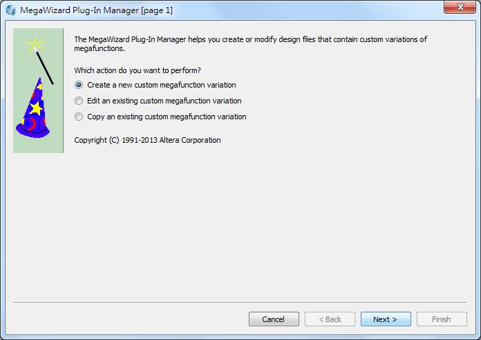
30 Using Quartus Add a PLL Megafunction A PLL uses the on-board oscillator (50 MHz for DE2-115 Board) to create a constant clock frequency as the input to the counter. To create the clock source, you will add a prebuilt library of parameterized modules (LPM) megafunction named ALTPLL. 30
31 1 2 31
32 1 32
33 1 33
34
35 1 2 for DE
36 Uncheck all the options 1 36
37 1 37
38 1 38
39 1 39
40 1 40 2
41 1 2 41
42 Assign the Pins 42
43 Assign the Pins Before making pin assignments
44 1 2 44
45 2 1 for DE2-115 Type M23, then push Enter 45 Now, you are finished creating your Quartus II design!
46 Create a Default TimeQuest SDC File 46
47 Create a Default TimeQuest SDC File Timing settings are critically important for a successful design. For this tutorial you will create a basic Synopsys Design Constraints File (.sdc) that the Quartus II TimeQuest Timing Analyzer uses during design compilation. For more complex designs, you will need to consider the timing requirements more carefully. 47
48 1 2 48

49 1 2 49
50 create_clock -period 20 [get_ports clk] create_clock -period name clk_16 derive_pll_clocks derive_clock_uncertainty set_input_delay 0 -clock clk_16 [all_inputs] set_output_delay 0 -clock clk_16 [all_outputs] If we do not use pll: create_clock -period 20 [get_ports clk] derive_clock_uncertainty set_input_delay 0 -clock clk [all_inputs] set_output_delay 0 -clock clk [all_outputs] 50
51
52 Compile and Verify Your Design 52
53 Compile Your Design After creating your design you must compile it. Compilation converts the design into a bitstream that can be downloaded into the FPGA. The most important output of compilation is an SRAM Object File (.sof), which you use to program the device. 53
54 1 54

55 Compilation Report Make sure there is no error. 55


56 Program the FPGA Device After compiling and verifying your design you are ready to program the FPGA on the development board. You download the SOF you just created into the FPGA using the USB-Blaster circuitry on the board. USB cable 12-volt adapter power 56
57 1 2 57
58 1 58
59 1 2 59
60 1 60
61 ~~Finish~~ 61

62 Demo Video 10 seconds countdown system 62
63 Configuring the Cyclone IV E FPGA 63
64 Configuring the FPGA JTAG programming In this method of programming, named after the IEEE standards Joint Test Action Group, the configuration bit stream is downloaded directly into the Cyclone IV E FPGA. The FPGA will retain this configuration as long as power is applied to the board; the configuration information will be lost when the power is turned off. AS programming In this method, called Active Serial programming, the configuration bit stream is downloaded into the Altera EPCS64 serial configuration device. It provides non-volatile storage of the bit stream, so that the information is retained even when the power supply to the DE2-115 board is turned off. When the board's power is turned on, the configuration data in the EPCS64 device is automatically loaded into the Cyclone IV E FPGA. 64

65 JTAG Chain (1/2) To use JTAG interface for configuring FPGA device, the JTAG chain on DE2-115 must form a close loop that allows Quartus II programmer to detect FPGA device. 65
 will be detected by Quartus II programmer.")
66 JTAG Chain (2/2) Shorting pin1 and pin2 on JP3 can disable the JTAG signals on HSMC connector that will form a close JTAG loop chain on DE2-115 board. Thus, only the on board FPGA device (Cyclone IV E) will be detected by Quartus II programmer. 66

67 Configuring the FPGA in JTAG Mode (1/2) This figure illustrates the JTAG configuration setup. 67

68 Configuring the FPGA in JTAG Mode (2/2) 1. Ensure that power is applied to the DE2-115 board. 2. Configure the JTAG programming circuit by setting the RUN/PROG slide switch (SW19) to the RUN position. 3. Connect the supplied USB cable to the USB Blaster port on the DE2-115 board. 4. The FPGA can now be programmed by using the Quartus II Programmer to select a configuration bit stream file with the.sof filename extension. 68

69 Configuring the EPCS64 in AS Mode (1/2) This figure illustrates the AS configuration setup. 69
70 Configuring the EPCS64 in AS Mode (2/2) 1. Ensure that power is applied to the DE2-115 board. 2. Connect the supplied USB cable to the USB Blaster port on the DE2-115 board. 3. Configure the JTAG programming circuit by setting the RUN/PROG slide switch (SW19) to the PROG position. 4. The EPCS64 chip can now be programmed by using the Quartus II Programmer to select a configuration bit stream file with the.pof filename extension. 5. Once the programming operation is finished, set the RUN/PROG slide switch back to the RUN position and then reset the board by turning the power switch off and back on; this action causes the new configuration data in the EPCS64 device to be loaded into the FPGA chip. 70
71 Programmer Object File Programmer Object File is a binary file (with the extension.pof) containing the data for programming a configuration device. A Programmer Object File for a configuration device can be generated by the Convert Programming Files command (File menu). 71
72 1 for DE
73
74 2 1 74
75 ~~Finish~~ 75
76 The End. Any question?
77 Reference "My First FPGA for Altera DE2-115 Board" by Terasic Technologies Inc. 3. "DE2-115 User Manual" by Terasic Technologies Inc. 77
My Second FPGA for Altera DE2-115 Board
 My Second FPGA for Altera DE2-115 Board 數位電路實驗 TA: 吳柏辰 Author: Trumen Outline DE2-115 System Builder ModelSim-Altera 2 DE2-115 System Builder 3 Introduction to DE2-115 System Builder (1/2) This section
CHAPTER 1 INTRODUCTION... 1 CHAPTER 2 ASSIGN THE DEVICE... 7 CHAPTER 3 DESIGN ENTRY CHAPTER 4 COMPILE AND VERIFY YOUR DESIGN...
 CONTENTS CHAPTER 1 INTRODUCTION... 1 1.1 DESIGN FLOW... 1 1.2 BEFORE YOU BEGIN... 2 1.3 WHAT YOU WILL LEARN... 6 CHAPTER 2 ASSIGN THE DEVICE... 7 2.1 ASSIGN THE DEVICE... 7 CHAPTER 3 DESIGN ENTRY... 11
Terasic DE0 Field Programmable Gate Array (FPGA) Development Board
 Development Board") Lecture FPGA-01 DE0 FPGA Development Board and Quartus II 9.1 FPGA Design Software Terasic DE0 Field Programmable Gate Array (FPGA) Development Board 1 May 16, 2013 3 Layout and Components of DE0 May 16,
Lecture FPGA-01 DE0 FPGA Development Board and Quartus II 9.1 FPGA Design Software Terasic DE0 Field Programmable Gate Array (FPGA) Development Board 1 May 16, 2013 3 Layout and Components of DE0 May 16,
CHAPTER 1 Introduction of the tnano Board CHAPTER 2 tnano Board Architecture CHAPTER 3 Using the tnano Board... 8
 CONTENTS CHAPTER 1 Introduction of the tnano Board... 2 1.1 Features...2 1.2 About the KIT...4 1.3 Getting Help...4 CHAPTER 2 tnano Board Architecture... 5 2.1 Layout and Components...5 2.2 Block Diagram
DE2 Board & Quartus II Software
 January 23, 2015 Contact and Office Hours Teaching Assistant (TA) Sergio Contreras Office Office Hours Email SEB 3259 Tuesday & Thursday 12:30-2:00 PM Wednesday 1:30-3:30 PM contre47@nevada.unlv.edu Syllabus
ECE 3610 Microprocessing Systems Lab #1 Verilog Design of the TOC Using Quartus II
 ECE 3610 Microprocessing Systems Lab #1 Verilog Design of the TOC Using Quartus II This lab manual presents an introduction to the Quartus II Computer Aided Design (CAD) system. This manual gives step-by-step
Tutorial for Altera DE1 and Quartus II
 Tutorial for Altera DE1 and Quartus II Qin-Zhong Ye December, 2013 This tutorial teaches you the basic steps to use Quartus II version 13.0 to program Altera s FPGA, Cyclone II EP2C20 on the Development
CPE 200L LABORATORY 4: INTRODUCTION TO DE2 BOARD UNIVERSITY OF NEVADA, LAS VEGAS GOALS: BACKGROUND:
 CPE 200L LABORATORY 4: INTRODUCTION TO DE2 BOARD DEPARTMENT OF ELECTRICAL AND COMPUTER ENGINEERING UNIVERSITY OF NEVADA, LAS VEGAS GOALS: Getting familiar with DE2 board installation, properties, usage.
My First Nios II for Altera DE2-115 Board
 My First Nios II for Altera DE2-115 Board Digital Circuit Lab TA: Po-Chen Wu Outline Hardware Design Nios II IDE Build Flow Programming the CFI Flash 2 Hardware Design 3 Introduction This slides provides
QUARTUS II Altera Corporation
 QUARTUS II Quartus II Design Flow Design Entry Timing Constraints Synthesis Placement and Routing Timing, Area, Power Optimization Timing and Power Analyzer Optimized Design 2 Can I still use a Processor?
Tutorial 3. Appendix D. D.1 Design Using Verilog Code. The Ripple-Carry Adder Code. Functional Simulation
 Appendix D Tutorial 3 This tutorial introduces more advanced capabilities of the Quartus II system. We show how Verilog code is organized and compiled and illustrate how multibit signals are represented
Lab 2 EECE473 Computer Organization & Architecture University of Maine
 Lab 2: Verilog Programming Instructor: Yifeng Zhu 50 Points Objectives: 1. Quatus II Programming assignment: PIN assignments, LEDs, switches; 2. Download and test the design on Altera DE2 board 3. Create
Tutorial 2 Implementing Circuits in Altera Devices
 Appendix C Tutorial 2 Implementing Circuits in Altera Devices In this tutorial we describe how to use the physical design tools in Quartus II. In addition to the modules used in Tutorial 1, the following
NOTE: This tutorial contains many large illustrations. Page breaks have been added to keep images on the same page as the step that they represent.
 CSE 352 Tutorial # 4 Synthesizing onto an FPGA Objectives This tutorial will walk you through the steps of implementing a design made in Active-HDL onto the Altera Cyclone II FPGA NOTE: This tutorial contains
CSCB58 - Lab 3. Prelab /3 Part I (in-lab) /2 Part II (in-lab) /2 TOTAL /8
 /2 Part II (in-lab) /2 TOTAL /8") CSCB58 - Lab 3 Latches, Flip-flops, and Registers Learning Objectives The purpose of this exercise is to investigate the fundamental synchronous logic elements: latches, flip-flops, and registers. Prelab
CSCB58 - Lab 3 Latches, Flip-flops, and Registers Learning Objectives The purpose of this exercise is to investigate the fundamental synchronous logic elements: latches, flip-flops, and registers. Prelab
Tutorial on Quartus II Introduction Using Verilog Code
 Tutorial on Quartus II Introduction Using Verilog Code (Version 15) 1 Introduction This tutorial presents an introduction to the Quartus II CAD system. It gives a general overview of a typical CAD flow
Laboratory Exercise 7
 Laboratory Exercise 7 Finite State Machines This is an exercise in using finite state machines. Part I We wish to implement a finite state machine (FSM) that recognizes two specific sequences of applied
University of Hawaii EE 361L. Getting Started with Spartan 3E Digilent Basys2 Board. Lab 4.1
 University of Hawaii EE 361L Getting Started with Spartan 3E Digilent Basys2 Board Lab 4.1 I. Test Basys2 Board Attach the Basys2 board to the PC or laptop with the USB connector. Make sure the blue jumper
My First FPGA Design Tutorial
 101 Innovation Drive San Jose, CA 95134 (408) 544-7000 http://www.altera.com TU-01002-1.0 Copyright 2007 Altera Corporation. All rights reserved. Altera, The Programmable Solutions Company, the stylized
Laboratory Exercise 8
 Laboratory Exercise 8 Memory Blocks In computer systems it is necessary to provide a substantial amount of memory. If a system is implemented using FPGA technology it is possible to provide some amount
IMPLEMENTING COUNTERS
 EECS:6660:0xxField Programmable Gate Arrays s11l1_fpga.fm - 1 Lab Assignment #1 Due Thursday, March 31 2011 IMPLEMENTING COUNTERS 1. OBJECTIVES - learning the VHDL implementation process using Language
Behavioral Modeling and Timing Constraints
 Introduction Behavioral modeling was introduced in Lab 1 as one of three widely used modeling styles. Additional capabilities with respect to testbenches were further introduced in Lab 4. However, there
Quartus II Introduction Using Verilog Design
 Quartus II Introduction Using Verilog Design This tutorial presents an introduction to the Quartus R II CAD system. It gives a general overview of a typical CAD flow for designing circuits that are implemented
ALTERA FPGAs Architecture & Design
 ALTERA FPGAs Architecture & Design Course Description This course provides all theoretical and practical know-how to design programmable devices of ALTERA with QUARTUS-II design software. The course combines
Quick Tutorial for Quartus II & ModelSim Altera
 Quick Tutorial for Quartus II & ModelSim Altera By Ziqiang Patrick Huang Hudson 213c Ziqiang.huang@duke.edu Download & Installation For Windows or Linux users : Download Quartus II Web Edition v13.0 (ModelSim
Quartus II Introduction Using Schematic Design
 Quartus II Introduction Using Schematic Design This tutorial presents an introduction to the Quartus R II CAD system. It gives a general overview of a typical CAD flow for designing circuits that are implemented
Tutorial on Quartus II Introduction Using Schematic Designs
 Tutorial on Quartus II Introduction Using Schematic Designs (Version 15) 1 Introduction This tutorial presents an introduction to the Quartus II CAD system. It gives a general overview of a typical CAD
ECE 353 Lab 4. MIDI Receiver in Verilog. Professor Daniel Holcomb UMass Amherst Fall 2016
 ECE 353 Lab 4 MIDI Receiver in Verilog Professor Daniel Holcomb UMass Amherst Fall 2016 Timeline and Grading for Lab 4 Lectures on 11/15 and 11/17 Due on 12/12 Demos in Duda hall Schedule will be posted
PRELAB! Read the entire lab, and complete the prelab questions (Q1- Q3) on the answer sheet before coming to the laboratory.
 on the answer sheet before coming to the laboratory.") PRELAB! Read the entire lab, and complete the prelab questions (Q1- Q3) on the answer sheet before coming to the laboratory. 1.0 Objectives In this lab you will get familiar with the concept of using the
PRELAB! Read the entire lab, and complete the prelab questions (Q1- Q3) on the answer sheet before coming to the laboratory. 1.0 Objectives In this lab you will get familiar with the concept of using the
The University of Toledo EECS:6660:0xxField Programmable Gate Arrays s09l1.fm - 1 Dr. A.D. Johnson
 EECS:6660:0xxField Programmable Gate Arrays s09l1.fm - 1 Lab Assignment #1 Due: Friday, February 27 2009 Introduction to Altera Quartus II Environment using VHDL Entry 1. Objectives - introduction to Quartus
EE 231 Fall Lab 1: Introduction to Verilog HDL and Altera IDE
 Lab 1: Introduction to Verilog HDL and Altera IDE Introduction In this lab you will design simple circuits by programming the Field-Programmable Gate Array (FPGA). At the end of the lab you should be able
PHYS 623 Field Programmable Gate Arrays Laboratory 1
 PHYS 623 Field Programmable Gate Arrays Laboratory 1 Ian Wisher, University of Wisconsin Physics Department Last edits October 19, 2015 1 Primer In this lab we will explore one of the most exciting developments
Introduction to VHDL Design on Quartus II and DE2 Board
 ECP3116 Digital Computer Design Lab Experiment Duration: 3 hours Introduction to VHDL Design on Quartus II and DE2 Board Objective To learn how to create projects using Quartus II, design circuits and
SOPC LAB1. I. Introduction. II. Lab contents. 4-bit count up counter. Advanced VLSI Due Wednesday, 01/08/2003
 SOPC LAB1 I. Introduction The purpose of this lab is to familiarize you with all the items in the kit. This tutorial tells you how to develop FPGA system in Quartus II. You are ready to begin using the
FPGA Design Challenge :Techkriti 14 Digital Design using Verilog Part 1
 FPGA Design Challenge :Techkriti 14 Digital Design using Verilog Part 1 Anurag Dwivedi Digital Design : Bottom Up Approach Basic Block - Gates Digital Design : Bottom Up Approach Gates -> Flip Flops Digital
EE178 Lecture Verilog FSM Examples. Eric Crabill SJSU / Xilinx Fall 2007
 EE178 Lecture Verilog FSM Examples Eric Crabill SJSU / Xilinx Fall 2007 In Real-time Object-oriented Modeling, Bran Selic and Garth Gullekson view a state machine as: A set of input events A set of output
EMT1250 LABORATORY EXPERIMENT. EXPERIMENT # 7: VHDL and DE2 Board. Name: Date:
 EXPERIMENT # 7: VHDL and DE2 Board Name: Date: Equipment/Parts Needed: Quartus II R Web Edition V9.1 SP2 software by Altera Corporation USB drive to save your files Objective: Learn how to create and modify
Lab 4: Register File and Memory 50 points Instructor: Yifeng Zhu Due: One week
 Objectives: Lab 4: Register File and Memory 50 points Instructor: Yifeng Zhu Due: One week Build Register File Build Instruction Memory and Data Memory 1. Overview A combinational circuit neither contains
Digital Design with FPGAs. By Neeraj Kulkarni
 Digital Design with FPGAs By Neeraj Kulkarni Some Basic Electronics Basic Elements: Gates: And, Or, Nor, Nand, Xor.. Memory elements: Flip Flops, Registers.. Techniques to design a circuit using basic
Lab 2: Introduction to Verilog HDL and Quartus
 Lab 2: Introduction to Verilog HDL and Quartus September 16, 2008 In the previous lab you designed simple circuits using discrete chips. In this lab you will do the same but by programming the CPLD. At
Typical applications where a CPLD may be the best design approach:
 By: Carlos Barberis, dba Bartek Technologies Description of Bartek s CPLD1 development board. For some of us CPLD s are familiar devices and for others just another acronym in the electronic device industry.
CHAPTER 1 INTRODUCTION Features About the KIT Getting Help... 7 CHAPTER 2 DE0-NANO BOARD ARCHITECTURE...
 1 CONTENTS CHAPTER 1 INTRODUCTION... 5 1.1 Features... 5 1.2 About the KIT... 7 1.3 Getting Help... 7 CHAPTER 2 DE0-NANO BOARD ARCHITECTURE... 8 2.1 Layout and Components... 8 2.2 Block Diagram of the
Quartus II Introduction Using Verilog Designs. 1 Introduction. For Quartus II 12.0
 Quartus II Introduction Using Verilog Designs For Quartus II 12.0 1 Introduction This tutorial presents an introduction to the Quartus II CAD system. It gives a general overview of a typical CAD flow for
Engineering 303 Digital Logic Design Spring 2017
 Engineering 303 Digital Logic Design Spring 2017 LAB 1 Introduction to Combo Logic and Quartus Deliverables: 0) A Simple Verilog Combinatorial Circuit 1) A Simple Block Diagram Combinatorial Circuit 2)
ECE 551: Digital System *
 ECE 551: Digital System * Design & Synthesis Lecture Set 5 5.1: Verilog Behavioral Model for Finite State Machines (FSMs) 5.2: Verilog Simulation I/O and 2001 Standard (In Separate File) 3/4/2003 1 Explicit
Physics 623. FPGA I Construction of a Synchronous Counter Aug. 4, 2008
 Physics 623 FPGA I onstruction of a Synchronous ounter Aug. 4, 2008 1 The Goal of This Experiment You will design a small digital circuit, download the design to a Field Programmable Gate Array (FPGA)
ECE 353 Lab 4. MIDI Receiver in Verilog. Professor Daniel Holcomb UMass Amherst Fall 2017
 ECE 353 Lab 4 MIDI Receiver in Verilog Professor Daniel Holcomb UMass Amherst Fall 2017 Timeline and Grading for Lab 4 Lectures on 11/14 and 11/16 Due on 12/11 (note: final exam 12/14) Demos in Duda hall
Laboratory Exercise 3
 Laboratory Exercise 3 Latches, Flip-flops, and egisters The purpose of this exercise is to investigate latches, flip-flops, and registers. Part I Altera FPGAs include flip-flops that are available for
Introduction to the Altera SOPC Builder Using Verilog Designs. 1 Introduction
 Introduction to the Altera SOPC Builder Using Verilog Designs 1 Introduction This tutorial presents an introduction to Altera s SOPC Builder software, which is used to implement a system that uses the
EEC180B DIGITAL SYSTEMS Spring University of California, Davis. Department of Electrical and Computer Engineering
 University of California, Davis Department of Electrical and Computer Engineering Tutorial: Instantiating and Using a PLL on the DE10 LITE Objective: This tutorial explains how to configure and instantiate
ENGN1640: Design of Computing Systems Topic 02: Design/Lab Foundations
 ENGN1640: Design of Computing Systems Topic 02: Design/Lab Foundations Professor Sherief Reda http://scale.engin.brown.edu School of Engineering Brown University Spring 2016 1 Topics 1. Programmable logic
The development board used in this class is ALTERA s DE The board provides the following hardware:
 Lab 1 The goal of this lab is to get familiar with the mechanics of designing digital systems using VHDL and ALTERA s FPGAs. The development board used in this class is ALTERA s DE2-115. The board provides
Chapter 2: Hardware Design Flow Using Verilog in Quartus II
 Chapter 2: Hardware Design Flow Using Verilog in Quartus II 2.1 Introduction to Quartus II System Development Software This chapter is an introduction to the Quartus II software that will be used for analysis
Lecture 7. Standard ICs FPGA (Field Programmable Gate Array) VHDL (Very-high-speed integrated circuits. Hardware Description Language)
 VHDL (Very-high-speed integrated circuits. Hardware Description Language)") Standard ICs FPGA (Field Programmable Gate Array) VHDL (Very-high-speed integrated circuits Hardware Description Language) 1 Standard ICs PLD: Programmable Logic Device CPLD: Complex PLD FPGA: Field Programmable
Standard ICs FPGA (Field Programmable Gate Array) VHDL (Very-high-speed integrated circuits Hardware Description Language) 1 Standard ICs PLD: Programmable Logic Device CPLD: Complex PLD FPGA: Field Programmable
University Program 3 Kit
 University Program 3 Kit VLSI Tutorial : LEDs & Push Buttons Version 02.00 System Level Solutions Inc. (USA) 14702 White Cloud Ct. Morgan Hill, CA 95037 2 System Level Solutions Copyright 2003-2005 System
CSE P567 - Winter 2010 Lab 1 Introduction to FGPA CAD Tools
 CSE P567 - Winter 2010 Lab 1 Introduction to FGPA CAD Tools This is a tutorial introduction to the process of designing circuits using a set of modern design tools. While the tools we will be using (Altera
2 nd Year Laboratory. Experiment: FPGA Design with Verilog. Department of Electrical & Electronic Engineering. Imperial College London.
 Department of Electrical & Electronic Engineering 2 nd Year Laboratory Experiment: FPGA Design with Verilog Objectives By the end of this experiment, you should know: How to design digital circuits using
A STANDARDIZED PROCEDURE FOR CLOSING TIMING ON OpenHPSDR FPGA FIRMWARE DESIGNS
 A STANDARDIZED PROCEDURE FOR CLOSING TIMING ON OpenHPSDR FPGA FIRMWARE DESIGNS by Joe A. Martin, PhD, K5SO August 26, 2014 Introduction! 2 Running the Quartus II TimeQuest Utility! 3 The *.SDC file! 6
Phase-Locked Loop Reconfiguration (ALTPLL_RECONFIG) Megafunction
 Megafunction") Phase-Locked Loop Reconfiguration (ALTPLL_RECONFIG) Megafunction UG-032405-6.0 User Guide This user guide describes the features and behavior of the ALTPLL_RECONFIG megafunction that you can configure
Phase-Locked Loop Reconfiguration (ALTPLL_RECONFIG) Megafunction UG-032405-6.0 User Guide This user guide describes the features and behavior of the ALTPLL_RECONFIG megafunction that you can configure
AN 818: Static Update Partial Reconfiguration Tutorial
 AN 818: Static Update Partial Reconfiguration Tutorial for Intel Stratix 10 GX FPGA Development Updated for Intel Quartus Prime Design Suite: 18.0 Subscribe Send Feedback Latest document on the web: PDF
ENGN1640: Design of Computing Systems Topic 02: Design/Lab Foundations
 ENGN1640: Design of Computing Systems Topic 02: Design/Lab Foundations Professor Sherief Reda http://scale.engin.brown.edu School of Engineering Brown University Spring 2017 1 Topics 1. Programmable logic
Chapter 2 Getting Hands on Altera Quartus II Software
 Chapter 2 Getting Hands on Altera Quartus II Software Contents 2.1 Installation of Software... 20 2.2 Setting Up of License... 21 2.3 Creation of First Embedded System Project... 22 2.4 Project Building
Section II. Software Settings
 Section II. Software Settings Configuration options can be set in the Quartus II and MAX+PLUS II development software. You can also specify which configuration file formats Quartus II or MAX+PLUS II generates.
4. Configuring Cyclone II Devices
 4. Configuring Cyclone II Devices CII51013-2.0 Introduction Cyclone II devices use SRAM cells to store configuration data. Since SRAM memory is volatile, configuration data must be downloaded to Cyclone
Outline. EECS Components and Design Techniques for Digital Systems. Lec 11 Putting it all together Where are we now?
 Outline EECS 5 - Components and Design Techniques for Digital Systems Lec Putting it all together -5-4 David Culler Electrical Engineering and Computer Sciences University of California Berkeley Top-to-bottom
Computer Aided Design Basic Syntax Gate Level Modeling Behavioral Modeling. Verilog
 Verilog Radek Pelánek and Šimon Řeřucha Contents 1 Computer Aided Design 2 Basic Syntax 3 Gate Level Modeling 4 Behavioral Modeling Computer Aided Design Hardware Description Languages (HDL) Verilog C
ALTERA FPGA Design Using Verilog
 ALTERA FPGA Design Using Verilog Course Description This course provides all necessary theoretical and practical know-how to design ALTERA FPGA/CPLD using Verilog standard language. The course intention
CSEE W4840 Embedded System Design Lab 1
 CSEE W4840 Embedded System Design Lab 1 Stephen A. Edwards Due January 31, 2008 Abstract Learn to use the Altera Quartus development envrionment and the DE2 boards by implementing a small hardware design
EE 231 Fall EE 231 Lab 2
 EE 231 Lab 2 Introduction to Verilog HDL and Quartus In the previous lab you designed simple circuits using discrete chips. In this lab you will do the same but by programming the CPLD. At the end of the
FPGA: FIELD PROGRAMMABLE GATE ARRAY Verilog: a hardware description language. Reference: [1]
![FPGA: FIELD PROGRAMMABLE GATE ARRAY Verilog: a hardware description language. Reference: [1]](/thumbs/80/81661285.jpg "FPGA: FIELD PROGRAMMABLE GATE ARRAY Verilog: a hardware description language. Reference: [1]") FPGA: FIELD PROGRAMMABLE GATE ARRAY Verilog: a hardware description language Reference: [] FIELD PROGRAMMABLE GATE ARRAY FPGA is a hardware logic device that is programmable Logic functions may be programmed
FPGA: FIELD PROGRAMMABLE GATE ARRAY Verilog: a hardware description language Reference: [] FIELD PROGRAMMABLE GATE ARRAY FPGA is a hardware logic device that is programmable Logic functions may be programmed
NIOS CPU Based Embedded Computer System on Programmable Chip
 1 Objectives NIOS CPU Based Embedded Computer System on Programmable Chip EE8205: Embedded Computer Systems This lab has been constructed to introduce the development of dedicated embedded system based
5. Configuring Cyclone FPGAs
 5. Configuring Cyclone FPGAs C51013-1.5 Introduction You can configure Cyclone TM FPGAs using one of several configuration schemes, including the active serial (AS) configuration scheme. This scheme is
SignalTap II with Verilog Designs. 1 Introduction. For Quartus II 13.1
 SignalTap II with Verilog Designs For Quartus II 13.1 1 Introduction This tutorial explains how to use the SignalTap II feature within Altera s Quartus II software. The SignalTap II Embedded Logic Analyzer
High-Performance FPGA PLL Analysis with TimeQuest
 High-Performance FPGA PLL Analysis with TimeQuest August 2007, ver. 1.0 Application Note 471 Introduction f Phase-locked loops (PLLs) provide robust clock management and clock synthesis capabilities for
Nikhil Gupta. FPGA Challenge Takneek 2012
 Nikhil Gupta FPGA Challenge Takneek 2012 RECAP FPGA Field Programmable Gate Array Matrix of logic gates Can be configured in any way by the user Codes for FPGA are executed in parallel Configured using
Design Flow Tutorial
 Digital Design LU Design Flow Tutorial Jakob Lechner, Thomas Polzer {lechner, tpolzer}@ecs.tuwien.ac.at Department of Computer Engineering University of Technology Vienna Vienna, October 8, 2010 Contents
Using Library Modules in Verilog Designs. 1 Introduction. For Quartus II 13.0
 Using Library Modules in Verilog Designs For Quartus II 13.0 1 Introduction This tutorial explains how Altera s library modules can be included in Verilog-based designs, which are implemented by using
NIOS CPU Based Embedded Computer System on Programmable Chip
 NIOS CPU Based Embedded Computer System on Programmable Chip 1 Lab Objectives EE8205: Embedded Computer Systems NIOS-II SoPC: PART-I This lab has been constructed to introduce the development of dedicated
AN 818: Static Update Partial Reconfiguration Tutorial
 AN 818: Static Update Partial Reconfiguration Tutorial for Intel Stratix 10 GX Updated for Intel Quartus Prime Design Suite: 18.1 Subscribe Latest document on the web: PDF HTML Contents Contents 1. Static
One and a half hours. Section A is COMPULSORY
 One and a half hours Section A is COMPULSORY An additional answersheet is provided for Question 4. Please remember to complete the additional answersheet with your University ID number and attach it to
ENGN1640: Design of Computing Systems Topic 02: Lab Foundations
 ENGN1640: Design of Computing Systems Topic 02: Lab Foundations Professor Sherief Reda http://scale.engin.brown.edu School of Engineering Brown University Spring 2014 1 Topics 1. Programmable logic 2.
Laboratory 4 Design a Muti-bit Counter and Programming a FPGA
 Laboratory 4 Design a Muti-bit Counter and Programming a FPGA For your report: The problem written in English The flowchart or function table to solve the problem if it is necessary The design entry included
Stratix FPGA Family. Table 1 shows these issues and which Stratix devices each issue affects. Table 1. Stratix Family Issues (Part 1 of 2)
") January 2007, ver. 3.1 Errata Sheet This errata sheet provides updated information on Stratix devices. This document addresses known issues and includes methods to work around the issues. Table 1 shows
January 2007, ver. 3.1 Errata Sheet This errata sheet provides updated information on Stratix devices. This document addresses known issues and includes methods to work around the issues. Table 1 shows
AN 825: Partially Reconfiguring a Design on Intel Stratix 10 GX FPGA Development Board
 AN 825: Partially Reconfiguring a Design on Intel Stratix 10 GX FPGA Updated for Intel Quartus Prime Design Suite: 18.1 Subscribe Latest document on the web: PDF HTML Contents Contents Partially Reconfiguring
EN2911X: Reconfigurable Computing Topic 02: Hardware Definition Languages
 EN2911X: Reconfigurable Computing Topic 02: Hardware Definition Languages Professor Sherief Reda http://scale.engin.brown.edu School of Engineering Brown University Spring 2014 1 Introduction to Verilog
Using Library Modules in Verilog Designs
 Using Library Modules in Verilog Designs This tutorial explains how Altera s library modules can be included in Verilog-based designs, which are implemented by using the Quartus R II software. Contents:
Configuration and programming minimodules MMfpga01 and MMfpga11
 MMfpga01 MMfpga11 Configuration and programming minimodules MMfpga01 and MMfpga11 1 Index 1. Instalation of the QUARTUS II Web Edition...3 2. How to install QUARTUS II Web Edition...5 3. Installation of
FPGA Introductory Tutorial: Part 1
 FPGA Introductory Tutorial: Part 1 This tutorial is designed to assist in learning the basics of the Altera Quartus II v9.0 software. Part 1 of the tutorial will cover the basics of creating a Project,
Laboratory Exercise 9
 Laboratory Exercise 9 Figure 1 shows a digital system that contains a number of -bit registers, a multiplexer, an adder/subtracter unit, a counter, and a control unit. Data is input to this system via
Section 3. System Integration
 Section 3. System Integration This section includes the following chapters: Chapter 9, Configuration, Design Security, and Remote System Upgrades in the Cyclone III Device Family Chapter 10, Hot-Socketing
Verilog Fundamentals. Shubham Singh. Junior Undergrad. Electrical Engineering
 Verilog Fundamentals Shubham Singh Junior Undergrad. Electrical Engineering VERILOG FUNDAMENTALS HDLs HISTORY HOW FPGA & VERILOG ARE RELATED CODING IN VERILOG HDLs HISTORY HDL HARDWARE DESCRIPTION LANGUAGE
INTRODUCTION TO DE2 SYSTEM INTERFACES
 EECS:6660:0xxField Programmable Gate Arrays s08l5a.fm - 1 Lab Assignment #5 INTRODUCTION TO DE2 SYSTEM INTERFACES 1. OBJECTIVES - Becoming familiar with the system interface to seven segment LED displays
ECE 574: Modeling and Synthesis of Digital Systems using Verilog and VHDL. Fall 2017 Final Exam (6.00 to 8.30pm) Verilog SOLUTIONS
 Verilog SOLUTIONS") ECE 574: Modeling and Synthesis of Digital Systems using Verilog and VHDL Fall 2017 Final Exam (6.00 to 8.30pm) Verilog SOLUTIONS Note: Closed book no notes or other material allowed apart from the one
ECE 574: Modeling and Synthesis of Digital Systems using Verilog and VHDL Fall 2017 Final Exam (6.00 to 8.30pm) Verilog SOLUTIONS Note: Closed book no notes or other material allowed apart from the one
Altera DE1 Board DE1. Development and Education Board. User Manual. Copyright 2006 Altera Corporation
 Altera DE1 Board DE1 Development and Education Board User Manual Version 1.1 Copyright 2006 Altera Corporation Chapter 2 Altera DE1 Board This chapter presents the features and design characteristics of
EMT1250 LABORATORY EXPERIMENT. EXPERIMENT # 6: Quartus II Tutorial and Practice. Name: Date:
 EXPERIMENT # 6: Quartus II Tutorial and Practice Name: Date: Equipment/Parts Needed: Quartus II R Web Edition V9.1 SP2 software by Altera Corporation USB drive to save your files Objective: Learn how to
AN 839: Design Block Reuse Tutorial
 AN 839: Design Block Reuse Tutorial for Intel Arria 10 FPGA Development Board Updated for Intel Quartus Prime Design Suite: 17.1 Subscribe Send Feedback Latest document on the web: PDF HTML Contents Contents
AN 825: Partially Reconfiguring a Design on Intel Stratix 10 GX FPGA Development Board
 AN 825: Partially Reconfiguring a Design on Intel Stratix 10 GX FPGA Development Board Updated for Intel Quartus Prime Design Suite: 17.1 Subscribe Send Feedback Latest document on the web: PDF HTML Contents
9. Configuration, Design Security, and Remote System Upgrades in Stratix V Devices
 January 2011 SV51010-1.2 9. Configuration, Design Security, and Remote System Upgrades in Stratix V Devices SV51010-1.2 This chapter contains information about the Stratix V supported configuration schemes,
Modeling Sequential Circuits in Verilog
 Modeling Sequential Circuits in Verilog COE 202 Digital Logic Design Dr. Muhamed Mudawar King Fahd University of Petroleum and Minerals Presentation Outline Modeling Latches and Flip-Flops Blocking versus