SBOX-Max Operating Manual
|
|
|
- Neil Webb
- 5 years ago
- Views:
Transcription

1 SBOX-Max
2 Contents 1 Safety instructions Precautions when lifting Risk of fire or explosion Risk of electrical shock Risk of burns Operating Re-fusing fittings 1 2 Getting to know your SBOX-Max 2 3 Quick instructions on fusing a joint 3 4 Scope of operation 4 5 Maintenance User maintenance Servicing 4 6 Manual data entry Data entry 5 7 Status bar Standard status bar Backing up record to memory card Sending data to USB memory device 6 8 General operation Power-up sequence BlueBox Warning messages Jointing cycle power interruption Joint lockout Service alarm Overheating Entry of traceability data 9 9 Information entry Messages on information entry screen Fitting information screen Modes of operation Fitting connection Fusion time selection or identification FUSAMATIC: Automatic mode Auto fittings only Manual Edit target voltage Edit target time Barcode mode (Barcode box only) Information shown on the barcode screen Starting the heating cycle Heating cycle Manually aborting the cycle Cycle completion - Cool time Cycle completion - With cooling cycle (Barcode boxes only) Memory full or nearly full Error messages User menus Adjust LCD contrast (Menu option 00) Set language (Menu option 01) Output joint record(s) (Menu option 02) and JointManager (Menu option 03) Send to Screen USB drive Select record(s) view/download Last joint All joints 21 EDOI8954 Issue 01
3 Joint range All complete All incomplete Matching criteria Sending data view/download System variables (Menu option 04) Remove user history (Menu option 05) Recover archived records (Menu option 06) Daylight saving (Menu option 07) User diagnostics menu Test / Calibration (01) Measure coil resistance (04) Measure ID resistance (06) Keypad and buzzer test (10) Test scanner (11) Specification Rights Accessories 26 Appendix A SBOX-Max Manual entry character set 27 A.1 Number character set. 27 A.2 ABC font set 27 A.2.1 Upper case characters 27 A.2.2 Lower case characters 27 A.3 Russian 28 A.3.1 Upper case characters 28 A.3.2 Lower case characters 28 A.4 Japanese 28 A.4.1 Upper case characters 28 A.4.2 Lower case characters 28 A.5 Symbol 28 EDOI8954 Issue 01
4 1 Safety instructions These operating instructions must be followed to ensure the safe operation of the SBOX-Max Electrofusion Control Unit and operators must be fully conversant with the safety instructions. Fusion Group Limited can offer operator training and regular maintenance where required. Only use undamaged equipment that has been properly maintained and calibrated. Refer to section 5 Maintenance of this operating manual for further information. 1.1 Precautions when lifting Where necessary, operators are advised to request for assistance when carrying, moving or lifting this equipment. 1.2 Risk of fire or explosion Do not use this equipment in combustible gaseous environments. 1.3 Risk of electrical shock This equipment delivers up to 48V AC via the output lead. The unit output power must not be energised without proper connection of the correct load (fitting) types. Avoid walking or standing on cables and ensure that the cables are safely routed. This equipment must be connected to a suitable electrical earth supply. Recommendation: For additional safety it is recommended that the unit be connected to a power supply incorporating suitable protection (such as a 30mA RCD). 1.4 Risk of burns The process of Electrofusion jointing generates heat in the fitting and pipe. The use of heat resistant gloves is strongly recommended, as is use of suitable eye protection. 1.5 Operating Only trained and authorised operators must operate this equipment, keep any unauthorised personnel away from the equipment. Children must not operate this equipment. 1.6 Re-fusing fittings The fusion operation must not be repeated on the same fitting since this can result in live parts becoming exposed on the fitting. EDOI8954 Page 1 Issue 01


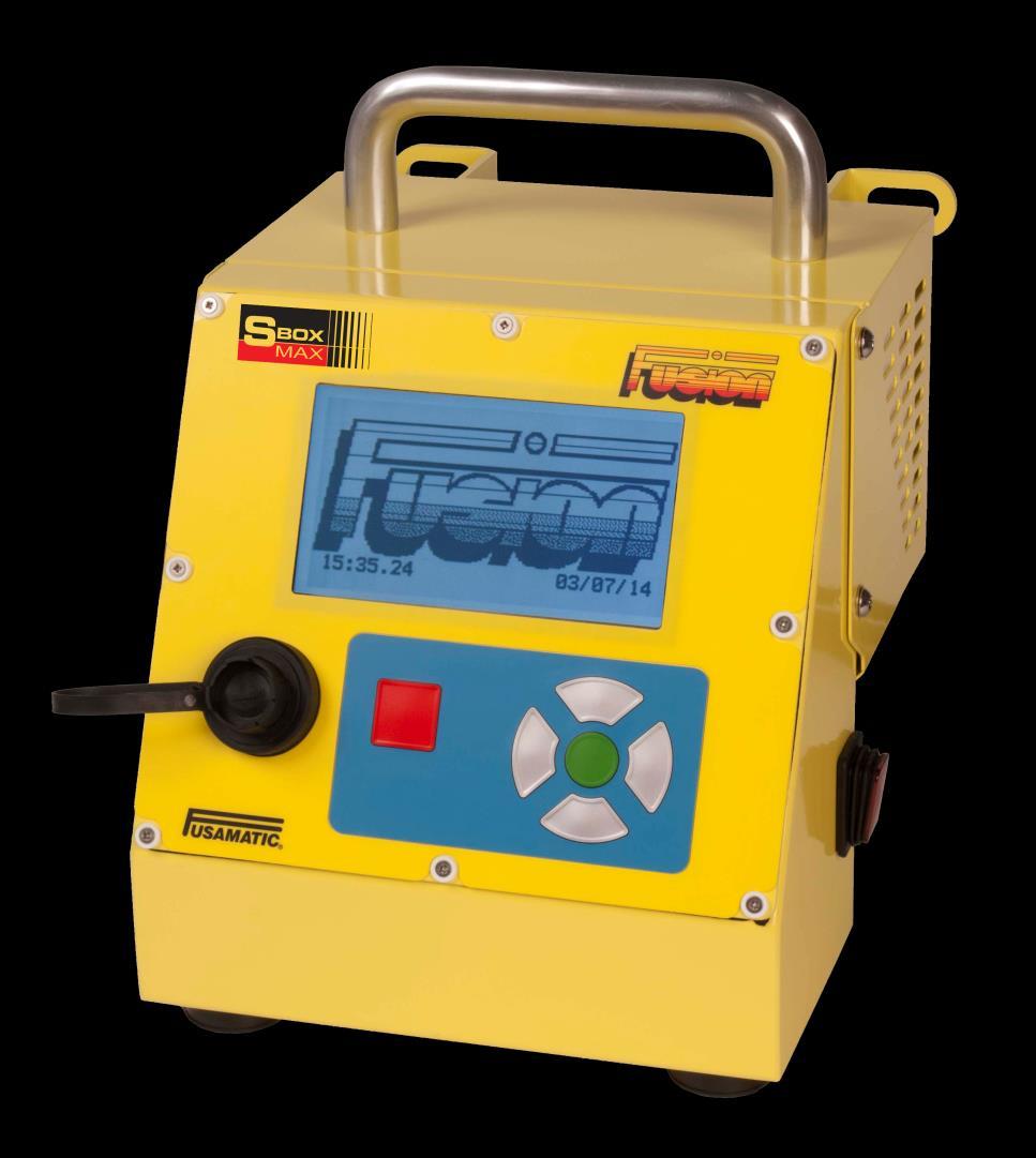
5 2 Getting to know your SBOX-Max The SBOX-Max is shown in detail in the illustrations below. Display Scroll up button Scroll right button USB A type connector Mains Input switch Stop or exit button LED s for BlueBox Scroll left button Scroll down button Start or enter button Output lead Scanner Ambient temperature sensor EDOI8954 Page 2 Issue 01
6 3 Quick instructions on fusing a joint 1. Connect the control unit to the mains supply and switch the mains input switch that is located on the side of the control unit to the ON position. 2. On power up the company logo, property of, date and time will be shown for 5 seconds. 3. Connect output lead to fitting (if Fusamatic red lead to red pin). 4. Press the green button to confirm that the pipe has been scraped and clamped. 5. Then press the green button to proceed. 6. To start welding for: a. Fusamatic Check and confirm weld time. b. Manual Enter manual weld voltage and time which can be accessed using the green button. c. Bar code box only Scan the bar code, check and confirm weld information. 7. Press green button to start the fusion cycle. 8. Barcode only if enabled, the cool time countdown timer will start when the fitting has finished fusing. Do not stop cool time or disconnect the leads from the fitting during this period. 9. After disconnecting the fitting the information screen will be displayed again. EDOI8954 Page 3 Issue 01
7 4 Scope of operation This unit is designed solely for the use of jointing of polyethylene (PE) Electrofusion fittings. 5 Maintenance 5.1 User maintenance Prior to connecting the unit to a supply or fitting always: Ensure that the lead ends are clean and free of damage. If the lead ends are not clean incorrect Fusamatic times may be recognised. Visually inspect the control unit enclosure for any damage. Ensure that the mains input plug is not damaged and remove any dirt. Check there is no damage to the input and output cable such as torn insulation or deep gouges. Ensure that the Barcode Reader is connected (Do not connect after the supply is turned on as the box or the scanner could be damaged). Ensure that the unit has been appropriately maintained and calibrated. Never use the control unit if plug, leads or enclosure are damaged, the service agent or Fusion Group Limited must carry out maintenance and service. Do not attempt to open the enclosure - there are no user serviceable parts inside. Note: The lead ends can be replaced using the following procedure. 1. Make sure the unit is disconnected from the power supply. 2. Unscrew the lead end connectors (anti clockwise). 3. Pull out the sense pin on the red lead end only. 4. Replace the sense pin on the red lead end only. 5. Replace the terminal connector ensuring it is fully tightened. 5.2 Servicing To ensure safe operation and optimum performance is maintained, either the manufacturer or an authorised service agent should check and calibrate this product at intervals of no longer than 12 months. For technical information contact the nearest service agent or the manufacturer, Fusion Group Limited via telephone on +44 (0) EDOI8954 Page 4 Issue 01
8 6 Manual data entry Manual data entry is required at various points in the operation of the unit. 6.1 Data entry There are two modes for character entry - Select mode and Edit mode. On activating Manual Data Entry the box is in Select mode. Select mode Characters/Actions are selected using the up, down, left and right buttons to move the Select cursor to the required icon. The selected character/action is accepted by pressing the green button. Edit mode To select Edit mode move the Select cursor to and press the green button, the Select cursor goes off (indicating Edit mode). The Edit cursor can then be moved within the edit string by using the left and right buttons. To insert a character, exit Edit mode (by pressing the green button, the Select cursor will re-appear over the icon) and select the required character as normal. Edit Cursor - If the Edit cursor cannot be seen the edit position is to the right of the last character in the entry field. Select Cursor If the Select cursor cannot be seen the box is in Edit Mode. Insert Characters - Characters will always be inserted to the left of the Edit cursor until the entry field is full. The Edit cursor will move to the right as characters are inserted. Delete Characters - Characters to the left of the Edit cursor can be deleted at any time by pressing the red button. The Edit cursor will move to the left as each character is deleted (until the Edit cursor is at the left most position). Extended Character - On certain fonts and characters, if the green button is held down for at least three seconds, the extended characters will be shown. Once the extended character pop-up is displayed, selection is carried out as described in Select Mode. NOTE: if the pop-up has been displayed and the extended character is not required, pressing the red button will exit the pop-up without adding the extended character. See appendix A. Restricted Entry Fields If the entry field requires specific characters, selection is restricted to those characters. Edit Operator A B C D E F G H I J K L M N O P Q R S T U V W X, 0. Y Z Accept text and exit (Action) - Delete the text string (Action) - Select Edit Mode (Action) - Change font being used (Action) - Switch between upper and lower case characters. (Action) - Space character. EDOI8954 Page 5 Issue 01
9 7 Status bar The status bar is shown at the bottom of most of the screens showing information on the service period and input supply. Each bar on the memory status indicates approximately 80 joint records. The spanner between the number of joints and the days to next service will flash, when either the number of joints or the days to next service are less than Standard status bar This status bar is shown when in information entry, fitting information and fusing screens :10 10:05: SBOX Memory status Number of joints to next service Number of days to next service Time Date Input voltage Input frequency 7.2 Backing up record to memory card This status bar is shown when backing up to memory card when joint is complete SD Memory status Number of joints to next service Number of days to next service Back up to memory card status 7.3 Sending data to USB memory device This status bar is shown when sending data to USB memory device (in review joint record(s), print joint record(s) and fast data transfer modes) Memory status Number of joints to next service Number of days to next service Download to USB status EDOI8954 Page 6 Issue 01
10 8 General operation 8.1 Power-up sequence Ensure that the input and output cables are fully rolled out. Barcode units only make sure to connect the Barcode Reader to the scanner lead before powering up the control unit. Connect the control unit to a suitable power supply (mains or generator). Put the mains input switch to the ON position it is located on the side of the unit the switch will illuminate when switched ON. The LCD (Liquid Crystal Display) indicates the following for approximately 5 seconds and on the barcode unit only a short audible tone will sound. Fusion Group 12:35:10 03/05/14 If ISO login method have been enabled the box will be inoperable until a valid operator barcode is scanned. The screen will either promt for a valid operator barcode, when a valid operator barcode is scanned to the box before the information entry screen will be displayed. If the red button is pressed the user menu will be displayed see section 13 user menu. 8.2 BlueBox If BlueBox has been enabled then a mobile device must be connected to the SBOX-Max via bluetooth with the BlueBox application open, before the information entry sceen is displayed. Refer to mobile device operating instruction for connecting via bluetooth. For further details contact Control Point on +44 (0) or info@controlpointllp.com. 8.3 Warning messages At power up certain warning messages may be displayed. These are: Jointing cycle power interruption Power fail detected! E08: Power fail heat phase to proceed If the jointing cycle or cool cycle has had a power interruption the above message will be shown. The message will be repeatedly displayed at power up until the green button has been pressed. EDOI8954 Page 7 Issue 01
11 8.3.2 Joint lockout If Joint Lockout has been enabled, the operator will be instructed to contact a supervisor whenever an incomplete joint is made. If the joint was incomplete a message prompting the operator to call the supervisor is displayed. Along with this prompt, a code letter between A and Z is displayed, along with the failed joint number. The operator is requested to quote the letter and joint number to the supervisor. The supervisor then issues a response code to the operator, who then enters this unlock code. If the code is entered incorrectly a new code letter is generated and the operator has to request a new response code. If the code is entered correctly the joint is then unlocked and the box can progress to the next joint. Turning the box off does not bypass the Joint Lock Out test, so the operator cannot proceed without obtaining and entering a valid response code. If the joint is classed as complete the box will progress to the next joint. If Joint Lockout is disabled the software will ignore the status of the joint Service alarm This indicates that either, the number of joints made or the number of days since the last service has been exceeded. The unit is in need of a service and contact should be made with nearest service centre. If Service Lockout has been disabled - press the green button to carry on using the box. Service required will be recorded on the joint data until the box is serviced and the service period been reset.! Service Required! Contact Fusion Group +44 (0) (0) Press to continue If Service Lockout has been enabled - the SBOX-Max is inoperable until it has been serviced and the service period has been reset.! Service Lock Out!! Service Required! Contact Fusion Group +44 (0) (0) ! Service Lock Out! EDOI8954 Page 8 Issue 01
12 8.3.4 Overheating SBOX-Max Electrofusion Control Unit!Warning! Internal Temperature too high Wait for SBOX to Cool Temperature Int ( ) 67.1 This indicates that the temperature inside the box has risen above +65 C. The box will remain inoperable until the internal temperature has dropped below +55 C. Refer to onscreen temperature gauge as shown above Entry of traceability data Traceability parameters such as operator code or location code, can be entered by barcode reader (if a suitable barcode exists), manually, or bypassed if not required. Traceability barcode styles should be Code128 or ITF 2 of 5. Barcode box only: At the appropriate parameter entry display, to enter a parameter using the barcode reader, locate the appropriate barcode and read it using the reader. 9 Information entry The unit will prompt for entry of operator, location, optional data 1, optional data 2 and project - if enabled - as follows:! Connect Fitting <Operator> <Location> <Optional Data 1> <Optional Data 2> <Project> Pipe Scraped & clamped? Continue Press To confirm Scroll onto the field required by using the up and down buttons on the keypad. When the appropriate field is highlighted, either press the left or right buttons to select one of the last five entries for the particular field or press the green button to enter the edit screen. On pressing the green button the following screen will be displayed. Edit Operator A B C D E F G H I J K L M N O P Q R S T U V W X, 0. Y Z + - EDOI8954 Page 9 Issue 01
13 Scroll to the appropriate character using the up, down, left and right buttons on the keypad. Then press the green button on the keypad to select the character. Repeat this until the required information is entered. Then select press the green button on the keypad to return to information entry screen. For more information see section 6.1 character entry screen. After entering project the edit project joint number screen will be displayed. If a previous project has been selected then the next project joint number will be displayed on edit project joint number screen. The project joint number can be made up of letters and numbers. The box will increment the number but not the letters. Any letters AFTER the number will be lost for the following joint. Barcode box only: If ISO operator login method entry is enabled and a valid operator barcode has been scanned then the operator information will be displayed. Note: that the operator, location, optional data 1, optional data 2, project and project joint number information is retained for subsequent joints. If any of operator, location, optional data 1, optional data 2 and project are not required then leave them empty or enter a space character. Up to 5 previously entered items of data are maintained for re-use. This History data can be accessed by pressing the left or right scroll buttons. After entering the required information scroll to Pipe scraped and clamped?. Scrape and then clamp the pipe(s) in accordance with governing authority procedures. Confirm this has been done by pressing the green button will be displayed against the prompt. Connect the fitting - when the fitting is connected, the top of the information screen will display Fitting Connected. The box will only continue when Pipe scraped and clamped? has been confirmed and the fitting is connected. When this has been done the cursor will scroll down to Continue. Press the green button to proceed to the fitting information screen. 9.1 Messages on information entry screen Connect fitting: Fitting not connected or a faulty fitting. Fitting Connected: Waiting to proceed to fitting information screen. Connect Lead: Faulty output lead contact service agent. EDOI8954 Page 10 Issue 01
14 10 Fitting information screen The unit will now prompt for entry of Component 1 batch, Component 2 batch, Optional batch and Fitting batch if enabled as follows: Fitting Details <Component 1 Batch> <Component 2 Batch> <Optional Batch> <Fitting Batch> Scroll onto the field required by using the up and down buttons on the keypad when the appropriate field is highlighted press the green button on the keypad. The following screen will be displayed. Edit Component 1 batch A B C D E F G H I J K L M N O P Q R S T U V W X, 0. Y Z + - Scroll to the appropriate character using the up, down, left and right buttons on the keypad. Then press the green button on the keypad to select the character. Repeat this until the required information is entered. Then select press the green button on the keypad to return to fitting information screen. For more information see section 6.1 character entry screen. Barcode box only scan the barcode by scrolling to the appropriate field then using the barcode reader to scan the information. If ISO tractability entry is enabled, a valid fitting batch and at least one component batch barcode has been scanned before the fitting barcode can be scanned. If the fitting is disconnected while on this screen the box will return back to the information entry screen Modes of operation The unit can operate in three distinct operating modes: Manual mode Fusamatic mode Barcode mode 10.2 Fitting connection In the case of Fusamatic mode, the red lead end should be connected to the red identification pin of an automatic fitting and the black lead end to the plain fitting pin. If SBOX-Max is connected to a non Fusamatic fitting or connected to a Fusamatic fitting in reverse, this will force manual or barcode mode operation. EDOI8954 Page 11 Issue 01
15 10.3 Fusion time selection or identification The SBOX-Max incorporates three modes of entering the fusion time for electrofusion jointing. The first mode is automatic using the Fusamatic system of fitting recognition with Fusamatic fittings. The second is manual mode, which enables manual entry of output voltage level and jointing cycle time. The third is barcode mode, which enables setting of fusion parameters (such as output voltage and fusion time/energy) by reading a fitting barcode that can usually be located on the side of the electrofusion fitting FUSAMATIC: Automatic mode In automatic mode, the SBOX-Max control unit interrogates the fitting and if it is a correctly connected Fusamatic type, establishes the fusion cycle time. Note: this requires the red lead end to be connected to the fitting pin with a red identifier and the black lead end connected to the plain fitting pin. From the information screen press the green button to confirm that the pipes are scraped and clamped. Then press the green button to proceed. When the automatic fitting has been identified, the display indicates the time and voltage see example below. Fusamatic Fitting <Component 1 Batch> <Component 2 Batch> <Optional Data> <Fitting Batch> Volts (V) 39.5 Time (s) 750 FUSE Press to confirm Check that the correct fusion time and voltage have been detected by verifying the information indicated on the fitting. Press the green button to fuse. If an incorrect fusion time is displayed, disconnect the fitting and then reconnect to try once more. If the time indicated on the display is still not correct. Manual mode can be forced by reversing the output lead connections Auto fittings only If the auto fitting option has been enabled the box will only recognise Fusamatic fittings and not recognise manual fittings. From the information screen press the green button to confirm that the pipes are scraped and clamped. Then press the green button to proceed. When the automatic fitting has been identified, the display indicates the time and voltage see example below. EDOI8954 Page 12 Issue 01
16 Fusamatic Fitting <Component 1 Batch> <Component 2 Batch> <Optional Data> <Fitting Batch> Volts (V) 39.5 Time (s) 750 FUSE Press to confirm Check that the correct fusion time and voltage have been detected by verifying the information indicated on the fitting. Press the green button to fuse. If an incorrect fusion time is displayed, disconnect the fitting and then reconnect to try once more. If a non Fusamatic fitting has been fitted and recognised then the following will be displayed.!warning!!manual Fitting Detected! Auto-Fitting Only Selected Replace Fitting 10.5 Manual If the fitting is not a Fusamatic type, or a Fusamatic fitting is connected in reverse (black lead end to the red sense pin of the fitting). Fitting Details <Component 1 Batch> <Component 2 Batch> <Optional Batch> <Fitting Batch> <Manual> From the information screen press the green button to confirm that the pipes are scraped and clamped. Then press the green button to proceed. The Fitting information screen will be displayed as above. Scroll onto <Manual> using the up and down buttons on the keypad then press the green button Edit target voltage The edit target voltage screen will be displayed. Edit Target Fusion voltage ---- A B C D E F G H I J K L M N O P Q R S T U V W X, 0. Y Z + - Scroll to the appropriate character using the up, down, left and right buttons on the keypad. Then press the green button on the keypad to select the character. For more information see section 6.1 character entry screen. Once the target voltage is entered the edit target time screen will be displayed. EDOI8954 Page 13 Issue 01
17 Edit target time The edit target time will be displayed on barcode and non-barcode boxes. Edit Target Fusion time ---- A B C D E F G H I J K L M N O P Q R S T U V W X, 0. Y Z + - Scroll to the appropriate character using the up, down, left and right buttons on the keypad. Then press the green button on the keypad to select the character. For more information see section 6.1 character entry screen. After the voltage and time have been entered the following screen will be displayed. Manual Fitting <Component 1 Batch> <Component 2 Batch> <Optional Data> <Fitting Batch> Volts (V) 39.5 Time (s) 60 FUSE Press to confirm Check that the voltage and time are correct for the fitting used. If not the voltage and time can be edited by scrolling to the item that needs editing and pressing the green button to edit the information. If voltage and time are correct press the green button to start the fusing cycle Barcode mode (Barcode box only) If the fitting is not a Fusamatic type, or a Fusamatic fitting is connected in reverse (black lead end to the red sense pin of the fitting). Fitting Details <Component 1 Batch> <Component 2 Batch> <Optional Data> <Fitting Batch> <Manual> <Fitting Barcode> EDOI8954 Page 14 Issue 01
18 From the information screen press the green button to confirm that the pipes are scraped and clamped. Then press the green button to proceed. The Fitting information screen will displayed as above. Scroll onto <Fitting barcode> using the up and down buttons on the keypad. Then using the barcode scanner scan the barcode on the fitting or press the green button to enter the fitting barcode manually the following screen will be displayed. Edit Fitting Barcode A B C D E F G H I J K L M N O P Q R S T U V W X, 0. Y Z + - Scroll to the appropriate character using the up, down, left and right buttons on the keypad. Then press the green button on the keypad to select the character. For more information see section 6.1 character entry screen. If the reader was used to scan the fitting barcode, a display similar to the example shown below will be presented: FUSI Coupler 63mm Coil Resistance (Ω)0.91 Measured Resistance (Ω)0.93 Volts (v) 40.0 Time (s) 35 Cool Time (s) 600 Press to continue Information shown on the barcode screen Note: the display indicates the following information: Item Detail Example Manufacturer Fusion Group Limited FUSI Fitting type Coupler Coupler Fitting size 63mm 63mm Coil resistance Theoretical resistance 0.91 Ohms Measured resistance Actual measured resistance 0.93 Ohms Volts Target voltage 40.0 Time Target time 35 seconds Cool Time Target cool time 600 seconds EDOI8954 Page 15 Issue 01
19 Check fitting details are correct then press the green button to continue. The fitting information screen is then displayed as shown below. Barcode Details <Component 1 Batch> <Component 2 Batch> <Optional Data> <Fitting Batch> Volts (V) 40.0 Time (s) 35 FUSE Press to confirm Check that the information is correct if correct press the green button to start the fusing cycle Starting the heating cycle The fusion (heating) cycle can start as soon as a valid time and voltage has been set-up (using Fusamatic, Manual or Barcodes). Press the green button on the key pad to start fusing cycle. If Blue Box has been enabled the display will prompt for a photograph to be taken by the connected mobile device before the fusion cycle can be started Heating cycle The output power will be energised and the display will indicate the fusion cycle time remaining, output voltage, output current for the present joint number see example below. Await completion of cycle. Heating Cycle Joint number 20 Time remaining (s) 76 Output voltage (V) 39.5 Output current (A)16.4 Observe cool time (s) Manually aborting the cycle Note: that the cycle can be aborted by pressing the red button on the keypad or disconnecting the main power. Also, disconnection of the fitting from the output cable will abort the process. Any manual aborting of the heating cycle will result in an error message being shown on the screen. WARNING: Disconnecting the input power or fitting is not recommended Cycle completion - Cool time When the heating cycle has been successfully completed, the display will show the following if there is no specified cooling time or it has been disabled. Disconnect the fitting as prompted the screen will then return to the information entry screen, but, EDOI8954 Page 16 Issue 01
20 DO NOT REMOVE THE CLAMPS UNTIL THE COOLTIME HAS ELAPSED! Joint status Joint number 20 Joint complete Disconnect Fitting Observe cool time! Cycle completion - With cooling cycle (Barcode boxes only) When the heating cycle has successfully reached completion, the display will indicate the following if there is a specified cooling time. Cooling Cycle Joint number 20 Time remaining (s) 0 Output voltage (V) Output current (A) Cool time (s) 273 WAIT FOR COOLING CYCLE COMPLETION BEFORE DISCONNECTING THE FITTING OR REMOVING THE CLAMPS! When cool time complete the screen will then display: Joint status Joint number 20 Joint complete Disconnect Fitting Disconnect the fitting as prompted and remove clamps. The process will then return to information entry screen. 11 Memory full or nearly full When the memory remaining falls and remains below 200 joints, the below screen is shown. The Joints Remaining counts down after each successive joint is made. The operator can make more joints by pressing the green button to Proceed. Joint Remaining 199! Box will be inoperative When database is full Retrieve and Erase data As soon as possible to Proceed EDOI8954 Page 17 Issue 01
21 When Joints Remaining reaches 0 (no more memory available) the memory is full. The box will be prevented from making any more joints until the joint data has been downloaded and the memory has been erased. Joints Remaining 0! INTERNAL DATABASE FULL For the box to operate Retrieve and Erase data to access User Menu On pressing the red button the User Menu will be displayed and the data transfer/print out can be done. See section 13 User menu. After downloading/printing the joint records the User Menu will re-appear. On pressing the red button, the final screen will be displayed. Joints Remaining 0! INTERNAL DATABASE FULL To erase the database And activate box Contact Engineer The database must now be erased to allow more joints to be made. Contact the nearest service centre. EDOI8954 Page 18 Issue 01
22 12 Error messages During the heating ( fusion ) cycle, the controller monitors the system for problems that could result in potentially poor joints. In the event of such a problem, a message is issued indicating its nature. The following shows the failure modes, likely causes and remedies. Mode Message Reason Possible cause Remedy E01 High output voltage Measured output voltage higher than 1.5% Surge in supply Check supply and adjust if necessary E02 Low output voltage Measured output voltage lower than 1.5% E03 Excessive output voltage Measured output voltage higher than 6.5% E04 High output current Measured current higher than 10% above previous sample E05 Low output current Measured current lower than 1.0A E06 Excessive output current Measured current higher than 20% above initial current measurement E07 pressed heat Operator pressed the stop switch to manually abort the cycle E08 Power Fail-Heat Phase A power failure was detected during the cycle E09 E10 E11 pressed during COOL Disconnected during cool The stop switch was pressed during the cooling phase The fitting was disconnected during the cooling phase Power Fail - Cool Phase A power failure was detected during the cycle Calibration error Input voltage too low Calibration error Surge in supply Calibration error Shorted turns in fitting due to poor preparation Disconnected fitting High fitting resistance Open circuit fitting Excessive shorted turns in fitting Operator intervention Power disconnected Generator out of fuel stop key manually operated Fitting disconnected Power disconnected Generator out of fuel If any other error messages appear on the screen, contact Fusion Group Limited via telephone on +44 (0) Contact supplier Check supply and adjust if necessary Contact supplier Check supply and adjust if necessary Contact supplier Cut out and replace fitting Only disconnect fitting in emergency Try another fitting Cut out and replace fitting Cut out and replace fitting Only press the stop switch in an emergency Only disconnect power in an emergency Refuel generator Only press the stop switch in an emergency Only disconnect fitting in an emergency Only disconnect power in an emergency Refuel generator EDOI8954 Page 19 Issue 01

23 13 User menus The User Menu allows the user to view and download joint data and System Variables, change contrast and erase the history data. To enter the User Menu, press the red button when in the information entry screen. Use the up and down buttons to highlight the required menu option then press the green button to select Adjust LCD contrast (Menu option 00) Selecting this option will allow the LCD contrast to be adjusted from the keypad. Pressing the up and down buttons on the keypad will adjust the LCD contrast in small steps. Pressing the left and right buttons on the key pad will adjust the LCD contrast in bigger steps. To confirm the LCD contrast and exit press the green button. Press the red button to exit without changing the contrast. Adjust LCD contrast = - = + = = 13.2 Set language (Menu option 01) If enabled for user menu selecting this option will allow the User to set the operating language of the SBOX-Max. Using the up and down button on the keypad select the required language. To confirm the language selected and exit, press the green button. Press the red button to exit without setting the language. Select Language 001 English 002 Français 003 Español 004 Deutsch 005 Italiano 006 Portugues 010 Svenska Scroll, Select, = Exit If not enabled for user menu selecting the following screen will be displayed if set language is selected.! Warning! Not enabled Press to continue EDOI8954 Page 20 Issue 01
24 13.3 Output joint record(s) (Menu option 02) and JointManager (Menu option 03) Selecting these options allows the operator to view joint data on the screen or download joint data to memory stick. View downloaded joint data in Microsoft Notepad from output joint records option or view joint data in JointManager from JointManager option. Send to: Review joint(s) Screen Select record(s): Last joint From 24 To 24 to Proceed Send to First use the up and down buttons to select Send to then using the left and right buttons to select the destination for the joint data Screen Display the joint data on the screen. See section select record(s) view/download USB drive Downloads the joint data to memory stick so the data can be viewed in Notepad (Unicode Font must be used) or JointManager depending on option selected. Connect the memory stick to the USB A connector on the front of the box. See section select record(s) view/download Select record(s) view/download Using up and down buttons scroll to Last joint. Using the left and right buttons select the required joint selection choosing from Last joint This gives the last joint fused. See section sending data view/download All joints This gives all the joints in the database. See section sending data view/download Joint range Allows a range of joints to be selected by scrolling down to From or To then using the left and right buttons on the keypad to select the joint range. See section sending data view/download All complete This gives all the complete joints in the database. See section sending data view/download. EDOI8954 Page 21 Issue 01
25 All incomplete This gives all the incomplete joints in the database. See section sending data view/download Matching criteria This gives joint data for an operator and/or project by scroll to operator or project press green button to enter criteria the following screen will be displayed. Operator A B C D E F G H I J K L M N O P Q R S T U V W X, 0. Y Z + - Scroll to the appropriate character using the up, down, left and right buttons on the keypad. Then press the green button on the keypad to select the character. For more information see section 6.1 character entry screen. If no match is found the following screen is displayed: Operation cancelled: No matching record Press to continue See section sending data view/download Sending data view/download When the required joint selection has been made scroll down to to proceed then the relevant information will be given. If the destination is the screen one joint at a time will be displayed. Use the up and down buttons on the keypad to scroll up and down the joint data. Press the green button to tab across to see the information that runs off the side of the screen. Use the left and right button to move on to the next joint. Press the red button on the keypad to exit. When joint data has been sent to USB drive the screen will display complete press to continue. The status bar at the bottom of the screen will show the status of the download see section 7 status bar. If the database is empty the following screen is displayed. Review Joint(s) No records! to Proceed EDOI8954 Page 22 Issue 01
26 13.4 System variables (Menu option 04) Selecting this option allows the operator to view the current system settings, e.g. serial number, property off, software version, joint number and the set options, on the screen or download current system settings to memory stick to view joint data in Microsoft Notepad. Use the up and down buttons on the keypad to scroll up and down the system variables. Press the green button to tab across to see the information runs off the side of the screen. Press the red button on the keypad to exit system variables. This information may be asked for when contacting Fusion Group. View On Screen Send to: Screen System Variables to Proceed Refer to section for how to select other Send to: destinations for the System Variables data. The first screen of information is shown below. System Variables Serial No.: SBOX30002 Plant Number: - Property Of: FUSION GROUP Software: 1.2 Voltage: 230v Joint No. information: Total 35 Scroll Exit Tab 13.5 Remove user history (Menu option 05) Selecting this option will allow all the user history to be erased. Press the green button to proceed and erase the user history. Press any other button to exit the Remove user history menu option Recover archived records (Menu option 06) Selecting this option will allow the user to recover records previously archived to the SD card. Press the green button to access the archived files, then use the up, down and green button to select the archive file to be recovered. When the green button is pressed the SBOX-Max will prompt the user to connect a memory stick, it will then proceed to transfer the selected data to the memory stick. Pressing the red button will cancel to procedure Daylight saving (Menu option 07) Selecting this option will allow the user to toggle the daylight saving. Press the green button to access the daylight saving option, then press the green button to add or remove an hour from the time. Press the red button to exit daylight saving. EDOI8954 Page 23 Issue 01
27 14 User diagnostics menu To enter the user diagnostic menu turn on the unit, when the logo screen is displayed press the red button then press the red button again Test / Calibration (01) The options in test / Calibration allow the operator to test relevant parts of the SBOX-Max. Press the green button to enter the test / calibration menu option then use the up and down buttons to select the relevant menu option then press green button to enter the menu option Measure coil resistance (04) The measure coil resistance option allows the fitting coil resistance to be checked via the screen display. Connect the lead ends to a fitting the coil resistance is displayed. Press the red button on the keypad to exit the measure coil resistance menu option and return to the test / calibration menu Measure ID resistance (06) The measure ID resistance option allows the Fusamatic time and resistance calibration to be checked via the screen display. Connect the lead ends to a Fusamatic fitting. Check that the correct fitting time is shown and there will also be a resistance displayed on the screen. Press the red button on the keypad to exit the measure ID resistance menu option and return to the test / calibration menu Keypad and buzzer test (10) The keypad and buzzer test option allows the keypad and buzzer to be tested. Press each button in turn; the respective button will be highlighted on the screen. If the green button is pressed the buzzer will also sound. Pressing the red button will result in the screen returning to the test / calibration menu after a brief period Test scanner (11) The test scanner option allows the barcode scanner to be tested. Scan a barcode then the barcode and the length of the barcode will be displayed on the screen. EDOI8954 Page 24 Issue 01
28 15 Specification Supply SBOX-Max / SBOX-Max BC Minimum Typical Maximum Input voltage 195v 230v 265v Input frequency 40Hz 50Hz 60Hz Input current 16A Generator rating 4.2KVA 6KVA Output SBOX-Max / SBOX-Max BC Minimum Typical Maximum Output voltage 40v Auto fitting 39.0v 39.5v 40.0v Output voltage barcode & manual 10.0v 48.0v Output current 2A 60A 60% Duty Cycle ISO A Peak current <60seconds 80A Operating modes SBOX-Max SBOX-Max BC Fusamatic 20 to 900 seconds Manual 10 to 3500 seconds Barcode Memory SBOX-Max / SBOX-Max BC Memory capacity Up to 2000 Records Backup to SD card Data output SBOX-Max / SBOX-Max BC USB memory device Environment SBOX-Max / SBOX-Max BC Minimum Maximum Operating temperature -10 C +40 C Storage temperature -15 C +55 C Environmental protection IP54 Dimensions Width Depth Height Without cloth bag & cables coiled 24cm 32cm 31cm Cable length SBOX-Max / SBOX-Max BC Input cable 3m Output cable 2.5m Weights SBOX-Max SBOX-Max BC Box with leads 16.8Kg 17.0Kg Cloth bag 2Kg Standards ISO Electrofusion ISO Classification ISO Operator Badge ISO Traceability Coding SBOX-Max / SBOX-Max BC P23US2FVKADX SBOX-Max BC EDOI8954 Page 25 Issue 01
29 16 Rights Due to Fusion's policy of continued development and improvement, we reserve the right to modify products without prior notice. 17 Accessories Below is a list of accessories and Fusion order numbers: Order No. Description Memory stick SBOX Barcode Kit (Fitted by an authorised service centre) mm Lead Ends EDOI8954 Page 26 Issue 01
30 Appendix A SBOX-Max Manual entry character set The SBOX-Max character sets are shown below: A.1 Number character set , ( - represents a SPACE). A.2 ABC font set A.2.1 Upper case characters A B C D E F G H I J K L M N O P Q R S T U V W X Y Z A.2.2 Lower case characters a b c d e f g h I j k l m n o p q r s t u v w x y z When the green button is held down for more than 3 seconds when on the selected character the following characters will be displayed. Selected character Displayed characters Selected character Displayed characters A À Á Â Ã Ä Å Ā Ǎ Ă Ą a à á â ã ä å ā ǎ ă ą C Ç Ć Ĉ Ċ Č c ç ć ĉ ċ č D Ď E È É Ê Ë Ē Ĕ Ė Ę Ě e è é ê ë ē ĕ ė ę ě G Ĝ Ğ Ġ Ģ g ĝ ğ ġ ģ H Ĥ h ĥ I Ì Í Î Ï Ĩ Ī Ĭ Į İ i ì í î ï ĩ ī ĭ į J Ĵ j ĵ K Ķ k ķ L Ĺ Ļ Ŀ Ł l ĺ ļ ŀ ł N Ñ Ń Ņ Ň Ŋ n ñ ń ņ ň ŋ O Ò Ó Ô Õ Ö Ø Ō Ŏ Ő o ò ó ô õ ö ø ō ŏ ő R Ŕ Ŗ Ř r ŕ ŗ ř S ß Ś Ŝ Ş Š s ś ŝ ş š T Ţ Ť t ţ U Ù Ú Û Ü Ũ Ū Ŭ Ů Ű Ų u ù ú û ü ũ ū ŭ ů ű ų W Ŵ w ŵ Y Ý Ŷ Ÿ y ỳ ÿ ŷ Z Ź Ż Ž z ź ż ž EDOI8954 Page 27 Issue 01
31 A.3 Russian SBOX-Max Electrofusion Control Unit A.3.1 Upper case characters A Б B Г Д E Ж З И Й K Л M H O П P C T У Ф X Ц Ч Ш Щ Ъ ЭЮ Я A.3.2 Lower case characters а б в г д е ж з и й к л м н о п р с т у ф х ц ч ш щ ъ эю я When the green button is held down for more than 3 seconds when on the selected character the following characters will be displayed. Selected character Displayed characters Selected character Ъ Ь Ы ъ ь ы A.4 Japanese A.4.1 Upper case characters アカサタナハマヤラワ A.4.2 Lower case characters ァヵサッナハマャラヮ - Displayed characters When the green button is held down for more than 3 seconds when on the selected character the following characters will be displayed. Selected character Displayed characters Selected character アイウエオァィゥェォ カキクケコヵ サシスセソサ タチツテトッチッテト ナヌニネノンナ ハヒフヘホハ マミムメモマ ヤユヨャュョ ラリルレロラ ワヲヮ A.5 Symbol! # $ % & ( ) * ` / : ; < = [ ] ^ { } ~ ± μ Ω Displayed characters EDOI8954 Page 28 Issue 01
32 Fusion Group Limited Smeckley Wood Close Chesterfield Trading Estate Chesterfield Derbyshire S41 9PZ Tel: + 44 (0) Fax: + 44 (0) sales@fusiongroup.com Web: EDOI8954 Page 29 Issue 01
OFFER VALID FROM R. 15 COLORS TEXT DISPLAYS SERIES RGB12-K SERIES RGB16-K SERIES RGB20-K SERIES RGB25-K SERIES RGB30-K
 OFFER VALID FROM 1.11.2016R. 15 COLORS TEXT DISPLAYS SERIES RGB12-K SERIES RGB16-K SERIES RGB20-K SERIES RGB25-K SERIES RGB30-K RGB Technology RGB Technology Ltd. is a Polish market-leading manufacturer
Myriad Pro Light. Lining proportional. Latin capitals. Alphabetic. Oldstyle tabular. Oldstyle proportional. Superscript ⁰ ¹ ² ³ ⁴ ⁵ ⁶ ⁷ ⁸ ⁹,.
 Myriad Pro Light Latin capitals A B C D E F G H I J K L M N O P Q R S T U V W X Y Z & Æ Ł Ø Œ Þ Ð Á Â Ä À Å Ã Ç É Ê Ë È Í Î Ï Ì İ Ñ Ó Ô Ö Ò Õ Š Ú Û Ü Ù Ý Ÿ Ž Ă Ā Ą Ć Č Ď Đ Ě Ė Ē Ę Ğ Ģ Ī Į Ķ Ĺ Ľ Ļ Ń Ň Ņ
Infusion Pump CODAN ARGUS 717 / 718 V - Release Notes. Firmware V
 Infusion Pump CODAN ARGUS 717 / 718 V - Release Notes Firmware V5.06.20165 Version Firmware V.5.06.20165 Release Date 28-May-2014 Update Type Optional Recommended Required (Field Safety Notice 1/2014 and
OFFER VALID FROM R. TEXT DISPLAYS SERIES A SERIES D SERIES K SERIES M
 OFFER VALID FROM 01.01.2016R. TEXT DISPLAYS SERIES A SERIES D SERIES K SERIES M SERIES M RGB Technology RGB Technology Ltd. is a Polish market-leading manufacturer of displays in LED technology. The company
KbdKaz 500 layout tables
 a ao a ao a o o o o o a a oo A o a a o a a oa ao oo A o a a o oa ao A a o a oa oa ao o a a a a o a A a a A ˆ a a A ˇ ao a a A a a A o Ao a a A Ao a o a a A ao a o a a A α a A a a a A o o a a A A a a A
Gator Automatic Butt Fusion Range Operating Manual
 Gator Automatic Butt Fusion Range www.fusiongroup.com Contents 1 Safety instructions 4 1.1 Precautions when lifting 4 1.2 Risk of fire or explosion 4 1.3 Risk of electrical shock 4 1.4 Risk of burning.
Operating Manual version 1.2
 VEHICLE TEMPERATURE AND HUMIDITY RECORDER Operating Manual version 1.2 Sp. z o.o. 41-250 Czeladź ul. Wojkowicka 21 tel. +48 32 763 77 77 fax. +48 32 763 75 94 www.mikster.pl mikster@mikster.pl Table of
TEX Gyre: The New Font Project. Marrakech, November 9th 11th, Bogusław Jackowski, Janusz M. Nowacki, Jerzy B. Ludwichowski
 TEX Gyre: The New Font Project Marrakech, November 9th 11th, 2006 Bogusław Jackowski, Janusz M. Nowacki, Jerzy B. Ludwichowski What is the TEX Gyre project about? What is the TEX Gyre project about? It
JOINT-STOCK COMPANY GIDROPRIVOD. RADIAL PISTON PUMPS OF VARIABLE DISPLACEMENT type 50 НРР
 JOINT-STOCK COMPANY GIDROPRIVOD RADIAL PISTON PUMPS OF VARIABLE DISPLACEMENT type 50 НРР Item purpose Radial piston pumps of variable displacement of the type 50НРР with adjustable delivery and constant
Operating Instructions
 CHEMICAL DRAINAGE SYSTEMS Fusion Lock Welding Unit Operating Instructions Table of Contents Specifications...................................................... 4 Important!.........................................................
Portable Appliance Tester KT75 OPERATORS MANUAL
 Portable Appliance Tester KT75 OPERATORS MANUAL CONTENTS 1.0 INTRODUCTION 3 2.0 SAFETY 3 3.0 FEATURES 4 3.1 Alpha numeric keypad 4 3.2 Expert Mode 4 3.3 Dual voltage operation 4 3.4 Help facility 4 3.5
MIVOICE OFFICE 400 MITEL 6863 SIP / MITEL 6865 SIP
 MIVOICE OFFICE 400 MITEL 6863 SIP / MITEL 6865 SIP USER GUIDE eud-1663_en / 1.0 R4.0 06.2015 Welcome... Welcome... Welcome to the user's guide for the desk phones Mitel 6863 SIP and Mitel 6865 SIP for
Designed to make your job easier MSA 2.0 and MSA 2.1 Electrofusion Units
 GF Piping Systems Designed to make your job easier MSA 2.0 and MSA 2.1 Electrofusion Units Your challenges are our drive Customers are asking for high efficiency, low cost of ownership, low weight and
Proweld Equipment Owner & Maintenance Manual Polymatic Electrofusion Machine
 Proweld Equipment Owner & Maintenance Manual Polymatic Electrofusion Machine 35 Green Street, PO Box 653, Malden, MA 02148 Tel: (781) 321-5409 - Fax (781) 321-4421 - Toll Free: (800) 343-3618 www.asahi-america.com
Configurations. User's guide
 Configurations User's guide Copyright Copyright Copyright - all rights reserved Avaya Inc. and Avaya GmbH & Co. KG Updated: 07/08 Reference number 4.999.112.584 Copying or passing on information from this
MIVOICE OFFICE 400 MITEL 6873 SIP USER GUIDE
 MIVOICE OFFICE 400 MITEL 6873 SIP USER GUIDE eud-1744_en / 1.3 R5.0 06.2017 NOTICE The information contained in this document is believed to be accurate in all respects but is not warranted by Mitel Networks
99 Washington Street Melrose, MA Phone Toll Free Visit us at
 99 Washington Street Melrose, MA 02176 Phone 781-665-1400 Toll Free 1-800-517-8431 Visit us at www.testequipmentdepot.com Table of Contents 1. General Safety Requirements... 1 2. Safety Terms and Symbols...
uninsta un in sta 9 weights & italics 5 numeral variations Full Cyrillic alphabet
 un in sta 9 weights & italics 5 numeral variations Full Cyrillic alphabet contemporary geometric web normal versitile universal adaptable neutral systematic consistant print humanist homogeneous unique
Calder Centaur Workshop Manual
 Calder Centaur Workshop Manual Revision: 04-03-2013 Covers all Calder Centaur electrofusion units incorporating the following circuit boards: CVTE0030 Issue 9 Power Board CVTE0034 Issue 9 Control Board
Solar Installation PV100 Operating Instructions
 Bracken Hill South West Industrial Estate Peterlee Co Durham SR8 2SW ENGLAND Tel: +44(0)191 5863511 www.seaward.co.uk sales@seaward.co.uk service@seaward.co.uk Part Number 388A552 Revision 1.2 March 2011
Polymer Electric. Operating Instructions. Control Unit SG-EFS 1X4 ZK2/1 8k2. Version 3
 Operating Instructions Control Unit SG-EFS 1X4 ZK2/1 8k2 Version 3 1003100 SG-EFS 104 ZK2/1 8k2 24 V=/~ 7500354 SG-EFS 134 ZK2/1 8k2 230 V~ Original instructions GmbH & Co. KG Polymer Electric Örlinger
HI-POT TESTER. User s Manual
 HI-POT TESTER 7620 User s Manual Contents 1. Before Use... 1.1Electric Shock Avoidance... 4 1.2 Grounding... 4 1.3 AC Power Supply... 4 1.4 Connecting Test Leads... 4 1.5 Warm Up... 4 1.6 External Control...
OPERATING INSTRUCTION
 OPERATING INSTRUCTION AUTORANGING MULTIMETER MAX Ω F C 10A MAX every 15 min. COM V SAFETY INFORMATION The following safety information must be observed to insure maximum personal safety during the operation
MEGAFLASHROM SCC+ SD
 MEGAFLASHROM SCC+ SD USER S MANUAL [DESCRIPTION] MegaFlashROM SCC+ SD is a combo cartridge with a SD card reader, an improved MegaFlashROM SCC+ and 512K RAM (optional) Each device is located in a subslot,
Prestigio P371 Users manual
 Prestigio P371 Users manual 1. IMPORTANT INFORMATION WARNING: TO PREVENT FIRE OR SHOCK HAZARD, DO NOT EXPOSE THIS MONITOR TO LIQUIDS OR MOISTURE. HIGH VOLTAGE EXISTS ON THIS MONITOR. DO NOT REMOVE THE
DIGITAL TORQUE ADAPTOR
 DIGITAL TORQUE ADAPTOR Model No: PRO238 PART NO: 1700638 OPERATING & MAINTENANCE INSTRUCTIONS GC12/16 INTRODUCTION Thank you for purchasing this CLARKE Torque Adaptor. This CLARKE product has been designed
IMPORTANT SAFETY INSTRUCTIONS SAVE THESE INSTRUCTIONS
 IMPORTANT SAFETY INSTRUCTIONS IMPORTANT SAFETY INSTRUCTIONS SAVE THESE INSTRUCTIONS WARNING (SAVE THESE INSTRUCTIONS): This manual contains important instructions that should be followed during installation
4WCE * 5 * : GEO. Air Products and Chemicals, Inc., 2009
 ХН Ч АН А 4WCE-600700* 5 9 2015. 1 93 : * : 600.700 600.730 1. 2 2. 2 3. 2 4. 3 5. 5 6. 7 7.,,, 8 8. 9 9., 10 10. 12 11., 13 12. 14 13. 16 14. 16 15. 17 16. 17 17., 18 18. 21 19., 24 20., 25 21., 26 22.
BS 181 SINGLE CHANNEL POWER SUPPLY USER MANUAL
 BS 181 SINGLE CHANNEL POWER SUPPLY USER MANUAL August 2016 This product is designed and manufactured by: ASL Intercom B.V. Zonnebaan 42 3542 EG Utrecht The Netherlands Phone: +31 (0)30 2411901 Fax: +31
Product Parts Front view... 2 Rear view... 2 Inside the product... 3 Scanner parts... 3 Control panel... 4
 Table of Contents Product Parts Front view................................................................. 2 Rear view.................................................................. 2 Inside the product...........................................................
DM-918 OPERATIONS MANUAL AUTORANGING MULTIMETER
 DM-918 OPERATIONS MANUAL AUTORANGING MULTIMETER SAFETY INFORMATION The following safety information must be observed to ensure maximum personal safety during the operation of this meter: This meter is
Gobo Projector XP 80W
 Gobo Projector XP 80W User Manual Order code: EQLED084 Safety advice WARNING FOR YOUR OWN SAFETY, PLEASE READ THIS USER MANUAL CARE- FULLY BEFORE YOUR INITIAL START-UP! Before your initial start-up, please
IO-INTERFACE. Procon. INSTALLATION MANUAL Version 1.01 MITSUBISHI ELECTRIC FOR INSTALLERS
 Procon IO-INTERFACE FOR INSTALLERS INSTALLATION MANUAL Version 1.01 For safe and correct use, please read this installation manual thoroughly before installing the PROCON IO-INTERFACE. MITSUBISHI ELECTRIC
MICRON DJ Booth System with Overhead Kit & CW Starcloth
 MICRON DJ Booth System with Overhead Kit & CW Starcloth User Manual Order code: EQLED014K Safety advice & product overview WARNING FOR YOUR OWN SAFETY, PLEASE READ THIS USER MANUAL CAREFULLY BEFORE YOUR
S-14 S-14. Compact Digital Multimeter. Compact Digital Multimeter
 S-14 Compact Digital Multimeter S-14 Compact Digital Multimeter SAFETY INFORMATION The following safety information must be observed to insure maximum personal safety during the operation at this meter
C.A 6165 Appliance multitester
 GB - Quick start guide C.A 6165 Appliance multitester Contents 1 General description... 3 1.1 Warnings and notes... 3 1.1.1 Safety warnings... 3 1.1.2 Warnings related to safety of measurement functions...
MIVOICE OFFICE 400 MITEL 6867 SIP / MITEL 6869 SIP
 MIVOICE OFFICE 400 MITEL 6867 SIP / MITEL 6869 SIP USER GUIDE eud-1664_en / 1.4 R5.0 HF2 10.2017 NOTICE The information contained in this document is believed to be accurate in all respects but is not
Operating Instructions
 Bracken Hill South West Industrial Estate Peterlee Co Durham SR8 2SW ENGLAND Tel: +44(0)191 5863511 www.seaward.co.uk sales@seaward.co.uk service@seaward.co.uk Part Number 344A550 Revision 1 2006 Seaward
RCD Fused Connection Unit Model: RCD10WPV. RCD Double Sockets Models: RCD05WAV, RCD06WPV, RCD07MAV, RCD08MPV. Installation & Operating Instructions
 RCD Fused Connection Unit Model: RCD10WPV RCD Double Sockets Models: RCD05WAV, RCD06WPV, RCD07MAV, RCD08MPV Installation & Operating Instructions General The Timeguard range of RCDs provides protection
LG-Nortel GDC-400 User manual
 LG-Nortel GDC-400 User manual 3 The purpose of this manual is to give a user the right way to use a GDC-400H wireless terminal and its accessories. This manual lists the matters that a user has to avoid
User Manual Digi-Sense 12-Channel Benchtop Data Logging Thermocouple Thermometer
 User Manual Digi-Sense 12-Channel Benchtop Data Logging Thermocouple Thermometer Model: 92000-01 THE STANDARD IN PRECISION MEASUREMENT Table of Contents Introduction... 3 Unpacking... 3 Initial Setup...3
OMRON PROGRAMMABLE CONTROLLER. Input terminals TIMER ADJUSTMENT
 PLC004 21/01/04 DISPLAY UNIT MANUAL 1 OMRON PROGRAMMABLE CONTROLLER Input terminals Input indication LED s Programming port OMRON SYSMAC CPM2A Expansion connector Potentiometers located behind peripheral
BS 287 DUAL CHANNEL POWER SUPPLY. User Manual. January 2017 V1.0
 BS 287 DUAL CHANNEL POWER SUPPLY User Manual January 2017 V1.0 Table of contents 1.0 SAFETY INSTRUCTIONS... 3 2.0 GENERAL DESCRIPTION PS 289... 4 3.0 MECHANICAL INSTALLATION... 5 4.0 MAINS POWER & SAFETY
Table of Contents. 3.1 Front/Rear Panel and User Interface Front Panel Rear Panel User Interface...
 General Warranty OWON warrants that the product will be free from defects in materials and workmanship for a period of 2 years (1 year for accessories) from the date of purchase of the product by the original
HI-POT TESTER User Manual
 HI-POT TESTER 7600 User Manual Contents 1. Safety...- 3-1.1 General...- 3 - AC Power Supply...- 4-1.2 Adjustment, Maintenance and Repair...- 5-1.3 Static Electricity...- 5-2. General:...- 6-2.1Packing
M A C 3 Wind Speed Alarm & Controller
 M A C 3 Wind Speed Alarm & Controller Installation Instructions Thank you for purchasing the MAC3 wind speed alarm and controller. This manual is designed to lead you through a step-by-step process to
Crossfire. User Manual. Order code: EQLED061
 Crossfire User Manual Order code: EQLED061 Safety advice WARNING FOR YOUR OWN SAFETY, PLEASE READ THIS USER MANUAL CAREFULLY BEFORE YOUR INITIAL START-UP! Before your initial start-up, please make sure
Line Interactive 1000VA/1400VA/2000VA Uninterruptible Power System
 USER MANUAL Line Interactive 1000VA/1400VA/2000VA Uninterruptible Power System 614-06762-00 IMPORTANT SAFETY INSTRUCTIONS SAVE THESE INSTRUCTIONS This manual contains important instructions for Line Interactive
USER S MANUAL Linear Programmable DC Power Supply APS
 USER S MANUAL Linear Programmable DC Power Supply APS-5333 www.tmatlantic.com Table of Contents 1. General Safety Requirements... 1 2. Safety Terms and Symbols... 2 3. General Characteristics... 3 4. Quick
Installation Manual RB-RWS20-E. Lite-Vision plus Remote Controller. Model name: English
 Model name: RB-RWS20-E Read this manual before using the RB-RWS20-E remote controller. Refer to the supplied with the indoor unit for any installation instructions other than operations of the remote controller.
BS 181 SINGLE CHANNEL POWER SUPPLY USER MANUAL
 BS 181 SINGLE CHANNEL POWER SUPPLY USER MANUAL Issue 2011 ASL Intercom BV DESIGNED & MANUFACTURED BY: ASL Intercom B.V. Zonnebaan 42 3542 EG Utrecht The Netherlands Tel: +31 (0)30 2411901 Fax: +31 (0)30
Operating Instructions
 Innovative by tradition. Operating Instructions Control Unit SG-RSV 239 Version 1 1003986 SG-RSV 239/24 24 V= 1005372 SG-RSV 239/36 36 V= 1003271 SG-RSV 239 50-150 V= Mayser GmbH & Co. KG Örlinger Straße
Operating Instructions
 PRIMETEST 100 PRIMETEST 100 Bracken Hill South West Industrial Estate Peterlee Co Durham SR8 2SW ENGLAND Tel: +44(0)191 5863511 www.seaward.co.uk sales@seaward.co.uk service@seaward.co.uk Part Number
Living. Keyfree Connected Smart Lock Manual. smart. The smarter way to protect your home
 smart Living Keyfree Connected Smart Lock Manual Please read the intructions before fitting and using the Keyfree Connected lock. The functions and design of this product can be changed without prior notice
QUICK START USER GUIDE. Data Logger Model L452
 QUICK START USER GUIDE Data Logger Model L452 Statement of Compliance Chauvin Arnoux, Inc. d.b.a. AEMC Instruments certifies that this instrument has been calibrated using standards and instruments traceable
Operating Instructions. Technical Equipment FRIAMAT. Fusion Units
 Operating Instructions FRIAMAT Fusion Units Technical Equipment 33 Contents Page 1. SAFETY 4 1.1 Dangers 4 1.2 Safety hints and tips 4 1.3 Use in accordance with the requirements 5 1.4 Sources of Danger
1.Installation 2.Channel 3. Setting 4.Service 5.Information
 7 8 1.Installation 2.Channel 3. Setting 4.Service 5.Information 8 9 12 13 15 17 This user's guide covers the installation Skyworth C3600B set-top box which includes step by step configuration of all features
Spectralink 7202/7212 Handset. User Guide IG, Edition 12.0 January 2018, Original document
 Spectralink 7202/7212 Handset User Guide Copyright Notice 2013-2018 Spectralink Corporation All rights reserved. Spectralink TM, the Spectralink logo and the names and marks associated with Spectralink
Spectralink 7722/7742 Handset. User Guide IG, Edition 11.0 April 2018, Original document
 Spectralink 7722/7742 Handset User Guide Copyright Notice 2013-2018 Spectralink Corporation All rights reserved. Spectralink TM, the Spectralink logo and the names and marks associated with Spectralink
Control unit SG-EFS 104/4L. EN Operating instructions. Innovative by tradition. Version SG-EFS 104/4L AC/DC 24 V
 Innovative by tradition. Control unit SG-EFS 104/4L EN Operating instructions Version 2 1004128 SG-EFS 104/4L AC/DC 24 V Original instructions Mayser GmbH & Co. KG Örlinger Straße 1 3 89073 Ulm GERMANY
DMX LED Starcloth Systems
 DMX LED Starcloth Systems User Manual Order codes: 3 x 2m with Stand & Bag Set (Black cloth, CW) - STAR01 2.2 x 1m DJ Skirt (Black cloth, CW) - STAR04 3 x 2m (Black cloth, CW) - STAR05 3 x 2m (White cloth,
IMPACT Order code: EQLED79
 Order code: EQLED77 IMPACT Order code: EQLED79 User manual Safety WARNING FOR YOUR OWN SAFETY, PLEASE READ THIS USER MANUAL CAREFULLY BEFORE YOUR INITIAL START-UP! CAUTION! Keep this equipment away from
RGB Power Batten. User Manual. Order code: EQLED032
 RGB Power Batten User Manual Order code: EQLED032 Safety advice WARNING FOR YOUR OWN SAFETY, PLEASE READ THIS USER MANUAL CARE- FULLY BEFORE YOUR INITIAL START-UP! Before your initial start-up, please
Micro-Ohmmeter Model 6292
 Micro-Ohmmeter Model 6292 Quick Start Guide ENGLISH www.aemc.com CHAUVIN ARNOUX GROUP Statement of Compliance Chauvin Arnoux, Inc. d.b.a. AEMC Instruments certifies that this instrument has been calibrated
DEUTSCH ENGLISH NEDERLANDS FRANÇAIS NORSK ITALANIO ČEŠTINA Hersteller DAB650SI
 DEUTSCH NEDERLANDS NORSK ČEŠTINA ENGLISH FRANÇAIS ITALANIO Hersteller Wörlein GmbH Tel.: +49 9103/71670 Gewerbestrasse 12 Fax.: +49 9103/716712 D 90556 Cadolzburg Email. info@woerlein.com GERMANY Web:
UV Spectra Batten 12 x 5W UV LEDs
 UV Spectra Batten 12 x 5W UV LEDs User Manual Convection cooled, no fan! Optional IR remote Order ref: LEDJ90E Order code: LEDJ98 Safety advice WARNING FOR YOUR OWN SAFETY, PLEASE READ THIS USER MANUAL
Installation and Operation Back-UPS BR1000G-IN / BR1500G-IN
 Installation and Operation Back-UPS BR1000G-IN / BR1500G-IN Important Safety Information Read the instructions carefully to become familiar with the equipment before trying to install, operate, service
PX Series Balances. Quick Start Guide. Please download the user manual from
 Scan QR Code with your WebCam for downloading the user instruction manual. PX Series Balances Quick Start Guide Please download the user manual from www.ohaus.com. EN-1 1. INSTALLATION 1.1 Select the
Installation & Calibration Manual
 Installation & Calibration Manual ScanWeight (System with Bluetooth module) ScanWeight-RF (System with Bluetooth and RF module) Lift Truck Onboard Check Weighing Initiated by Barcode Scanner ScanWeight
«, 68, 55, 23. (, -, ).,,.,,. (workcamps).,. :.. 2
.,,.,,. (workcamps).,. :.. 2") ,.. 2017. 49.03.03. -,......,..... 2017 «, 68, 55, 23. (, -, ).,,.,,. (workcamps).,. :.. 2 ......4 1..6 1. 1...6 1. 2...9 1.3...14 2...20 2.1.........20 3. 22 3.1...22 3.2...34 3.3,.41.....44..... 48 A
,.. 2017. 49.03.03. -,......,..... 2017 «, 68, 55, 23. (, -, ).,,.,,. (workcamps).,. :.. 2 ......4 1..6 1. 1...6 1. 2...9 1.3...14 2...20 2.1.........20 3. 22 3.1...22 3.2...34 3.3,.41.....44..... 48 A
Slimline CW & WW Series
 Slimline CW & WW Series 1 x 20W COB LED User Manual Convection cooled, no fan! Optional IR remote Order ref: LEDJ90E White housing versions Order codes: LEDJ61-1CW20 Black housing LEDJ61A - 1CW20 White
OPERATING MANUAL FOR THE 30KV A.C. TEST SET P123. Bicotest High Voltage Products Ltd
 OPERATING MANUAL FOR THE 30KV A.C. TEST SET P123 Product: High Voltage AC Test Set Type: P123 Bicotest High Voltage Products Ltd Hellesdon Park Road, Drayton High Road, Norwich NR6 5DR United Kingdom Phone
Installation Manual. 65 Interactive LED/LCD. Model: HILF65101 (64.56 )
") Installation Manual 65 (64.56 ) Model: HILF65101 65 Interactive LED/LCD QUICK SETUP GUIDE For further information, see the user manual. Please contact directly if you have questions on the use of the touch
Installation Manual 65 (64.56 ) Model: HILF65101 65 Interactive LED/LCD QUICK SETUP GUIDE For further information, see the user manual. Please contact directly if you have questions on the use of the touch
Economy Single Channel Output DC Power Supply
 Economy Single Channel Output DC Power Supply User Manual www.owon.com.cn Feb. 2019 edition V1.1.0 Copyright LILLIPUT Company. All rights reserved. The LILLIPUT's products are under the protection of the
Control unit SG-EFS 104/2W. EN Operating instructions. Innovative by tradition. Version SG-EFS 104/2W 24 V=/~
 Innovative by tradition. Control unit SG-EFS 104/2W EN Operating instructions Version 0.9 1005196 SG-EFS 104/2W 24 V=/~ Original instructions Mayser GmbH & Co. KG Örlinger Straße 1 3 89073 Ulm GERMANY
DS3 / DS31 User Manual
 DS3 / DS31 User Manual Please read the following warnings before using the product.. Contents of manual may differ based on the software version of products. Please visit web site(www.mobilebaseglobal.com)
Model HM-535 Power Supply Installation and Service Instructions
 Model HM-535 Power Supply Installation and Service Instructions 430-535 0104 2004 Heritage MedCall, Inc SENTRY INSTALLATION & SERVICE INSTRUCTIONS POWER SUPPLY UNIT Model HM-535 IMPORTANT SAFETY INSTRUCTIONS
O P E R A T O R S M A N U A L
 O P E R A T O R S M A N U A L Safety Instructions When using your heat press, basic precautions should always be followed, including the following:.. 3. 4. 5. 6. 7. 8. 9. 0.. Read all instructions. Use
GV3000/SE Operator Interface Module (OIM) User Guide Version 2.0 M/N 2RK3000
 User Guide Version 2.0 M/N 2RK3000") GV3000/SE Operator Interface Module (OIM) User Guide Version 2.0 M/N 2RK3000 Instruction Manual D2-3342-2 The information in this manual is subject to change without notice. Throughout this manual, the
GV3000/SE Operator Interface Module (OIM) User Guide Version 2.0 M/N 2RK3000 Instruction Manual D2-3342-2 The information in this manual is subject to change without notice. Throughout this manual, the
installation quick guide integrated access control & environmental monitoring
 installation quick guide integrated access control & environmental monitoring Introduction This Installation Quick Guide is suitable for standard wallmountable AX300 controllers. Illustrative technical
DIGITAL GEAR PUMP DRIVE OPERATING MANUAL: Model No.
 OPERATING MANUAL: DIGITAL GEAR PUMP DRIVE Model No. 75211-70 Digital Gear Pump Drive 75211-70 A-1299-1142 Edition 01 Cole-Parmer 1-800-323-4340 ((U.S. and Canada only) 11 (847) 549-7600 (Outside U.S.)
Installation & Calibration Manual
 IMPORTANT NOTE: Please read first the HID ProxPoint Plus card reader information on the end of this manual referring to the programming method that is required to get the system up and running. RFID Proximity
DC100 Digital Dispenser Operating Manual
 DC100 Digital Dispenser Operating Manual 2015 Fisnar Phone: (262)253-8600 E-mail: info@fisnar.com Table of Contents Product Safety Statement 4 Specifications 6 Accessories 6 External Controls 7 Machine
CALOG CALOG - LC DISPLAY. Loadcell Display. English Users Manual. Rev. 1.10
 CALOG C A L I B R AT O R S CALOG - LC DISPLAY Loadcell Display English Users Manual Rev. 1.10 Table of Contents! Contents! 1.0 Introduction...2! 2.0 Getting Started...2! 2.1 Keypad...2! 2.2 Display...2!
121000TP227S USER'S MANUAL
 121000TP227S USER'S MANUAL TABLE OF CONTENTS FEATURE LIST SAFETY INSTRUCTIONS INTRODUCTION LOCATION OF CONTROLS FUNCTION BUTTONS MENU SETTINGS CALLER ID INFORMATION DISPLAY MESSAGES CALLER ID SYSTEM OPERATION
Intrinsically safe batch controller Batching Master 110i
 Intrinsically safe batch controller Batching Master 110i Installation Guide BVS 04 AT E 172 Revision 12.2 IBS BatchControl GmbH Im Sträßchen 2-4 Tel.: ++49 2441 9199 801 53925 Kall Fax.: ++49 2441 9199
MAC3 Wind Speed Alarm & Controller. Installation Instructions
 MAC3 Wind Speed Alarm & Controller Installation Instructions Table of Contents Overview... 3 Installation... 3 Optional Equipment... 10 Dual Sensor Operation... 10 Other Optional Equipment... 10 Operation
Polymer Electric. Operating Instructions. Control Unit SG-RST 153. Version 0.3
 Operating Instructions Control Unit SGRST 153 Version 0.3 1004931 SGRST 153 Original instructions GmbH & Co. KG Örlinger Straße 1 3 89073 Ulm GERMANY Tel.: +49 731 20610 Fax: +49 731 2061222 EMail: info.ulm@mayser.com
w w w. p r o l i g h t. c o. u k TRI PAR 64 Order code: LEDJ48 - Black Order code: LEDJ49 - Polished USER MANUAL
 w w w. p r o l i g h t. c o. u k TRI PAR 64 Order code: LEDJ48 - Black Order code: LEDJ49 - Polished USER MANUAL Safety WARNING FOR YOUR OWN SAFETY, PLEASE READ THIS USER MANUAL CAREFULLY BEFORE YOUR INITIAL
Autoranging True RMS Multimeter User Manual
 Autoranging True RMS Multimeter User Manual Please read this manual before switching the unit on. Important safety information inside. Contents Page 1. Safety Information... 4 2. Safety Symbols... 5 3.
MICRON DJ Booth Tri-colour Starcloth
 MICRON DJ Booth Tri-colour Starcloth User Manual Order code: EQLED014C Safety advice WARNING FOR YOUR OWN SAFETY, PLEASE READ THIS USER MANUAL CAREFULLY BEFORE YOUR INITIAL START-UP! Before your initial
EntraGuard Bronze. Quick Start Guide. Telephone Entry. 1.0 Specifications. 2.0 Unit Installation
 The EntraGuard Bronze is a residential telephone keypad entry system which allows a homeowner to communicate directly with visitors and provide access by using any phone extension in the home. Because
Digital Photo Frame With Alarm Clock Model DPF-363
 Digital Photo Frame With Alarm Clock Model DPF-363 Transformer 100-240V~ 50Hz, 2.5W Frame input 5V 500mA Please read these instructions before use and retain for future reference Table of Contents 1. Safety.....3
Integriti User Manual. Elite / EliteX LCD Terminal Keypads
 Integriti User Manual Elite / EliteX LCD Terminal Keypads INNER RANGE recommends that all INTEGRITI systems are installed & maintained by FACTORY CERTIFIED TECHNICIANS. For a list of Accredited Dealers
w w w. p r o l i g h t. c o. u k STAGE PAR 64
 w w w. p r o l i g h t. c o. u k STAGE PAR 64 Order code: LEDJ40 (Black) Order code: LEDJ41 (Polished) Order code: LEDJ42 (Black) Order code: LEDJ43 (Polished) Order code: LEDJ44 (Black) Order code: LEDJ45
DLRO 200 High Current, Low Resistance Ohmmeter
 M DLRO 200 High Current, Low Resistance Ohmmeter USER MANUAL GSAFETY WARNINGS THESE SAFETY WARNINGS MUST BE READ AND UNDERSTOOD BEFORE THE INSTRUMENT IS USED. n DLRO200 is supplied without a plug terminating
CF3000 Dealer Diagnostic Tool Instruction Manual
 CF3000 Dealer Diagnostic Tool Instruction Manual Table of Contents: About the CF3000......3 Important Precautions......4 Components....5 Charging the CF3000......7 Licensing the CF3000.......8 Updating
Blitzer Strobe. User Manual. Order code: EQLED366
 Blitzer Strobe User Manual Order code: EQLED366 Safety advice WARNING FOR YOUR OWN SAFETY, PLEASE READ THIS USER MANUAL CAREFULLY BEFORE YOUR INITIAL START-UP! Before your initial start-up, please make
USER MANUAL. For XLCD17-LED XLCD19-LED
 USER MANUAL For XLCD17-LED XLCD19-LED 2 TABLE OF CONTENTS CE information ------------------------------------------------------------------------ 4 Safety Precautions -------------------------------------------------------------------
ServView 17S KVM Switch
 ServView 17S KVM Switch Quick Start Guide KVT128AE-UK-8-R2 KVT128AE-UK-16-R2 CONTENTS Chapter 1 Getting Started 1.1 Important Safeguards 1 1.2 Regulatory Notice 1-2 1.3 Before Installation 2 Chapter 2