Safety Test Switch. Reference Handbook. STS-reference-en v
|
|
|
- Beverly Watts
- 5 years ago
- Views:
Transcription

1 Safety Test Switch Reference Handbook STS-reference-en v
2 Copyright Notice All information provided in this document is the property of SECUCONTROL. SECUCONTROL grants its customers or potential customers the right to download, copy, store and print this document for the sole purpose of assisting them in the correct application of the products mentioned in this document. All other uses of this document are expressely prohibited. Intellectual Property Notice This publication contains proprietary information under protection of the following (among others) patents: DE , DE , US 7,271,357 and US 7,884,597. Contents Disclaimer Although the information and recommendations in this document are presented in good faith and believed to be correct as of publication date, SECUCONTROL makes no representations as to the completeness or accuracy thereof. In no event shall SECUCONTROL be responsible for damages of any nature resulting from the use of or reliance upon the contents of this document. Continuous Improvements Products developed by SECUCONTROL are continuously improved. The information in this document may, therefore, be out of date. Please make sure you have the latest release of this document before proceeding by checking its name and revision code. This information is printed on the front cover of this document, underneath the title. The latest release of this document can be downloaded from Alternatively, you may contact SECUCONTROL at any of the addresses provided on the rear cover of this document.
3 Contents 1 Introduction 1 The Safety Test Switch Key Features Unpacking Part Number and Manufacturing Date Location Safety Symbols General Safety Instructions Principle of Operation 3 Closed Circuit Open Circuit Signal Injection Application 5 Schematic Symbols Typical Connection Schematic Installation 7 Panel Cutouts, Drilling Plans and Mounting Wiring Operation 9 6 Technical Specifications 11 Electrical Mechanical Dimensional Drawings Models Available 13 Number of Banana Jacks Accessories 15 Jumper Cable Current Measurement Probe Safety Test Switch 19 Rack Plates i
4 ii CONTENTS Covers for 19 Safety Test Switch Rack Plate Cutouts Spare Parts 19 Disconnect Pins Dust Covers Fitting Set Ordering Information 21 Part Numbers Available Configurations
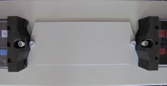
5 1 Introduction The Safety Test Switch The Safety Test Switch (ST Switch) is a test switch for interfacing substation devices (protection relays, fault recorders, revenue meters,... ) to the voltage and current transformers and to other equipment on the system side of a power grid. The ST Switch uses disconnect pins to isolate the substation devices from the system side equipment. Once isolated, secondary injection can be performed using banana jacks on the front side of the test switch. Key Features Finger-safe Test Switch and Disconnect Pins increase safety during testing. Disconnect Pins are keyed to the corresponding parts of the Test Switch, preventing mistakes and errors during test. Visible open/closed contacts via status windows Extremely low internal resistance (< 2 mω) helps reduce heat inside cabinets and panels. Available in 10 or 14 pole configurations. Unpacking Unpack the product carefully and make sure that all pertinent parts like dust covers and screws are put aside so they will not be lost. Check the contents against the packing list. If any of the contents listed are missing, please contact SECUCONTROL immediately (see contact information at the rear cover of this manual). Examine the product for any shipping damage. If the product is damaged, notify the shipping company without delay. Only the consignee (the person or company receiving the unit) can file a claim against the carrier for shipping damage. 1
6 1. INTRODUCTION Part Number and Manufacturing Date Location Part number and manufacturing date are stated on a label on the right side of the Test Switch. Safety Symbols The following symbols are located on different parts of the equipment and in this manual: Paragraphs marked with this symbol contain information which, if not properly followed, may cause damage to the equipment and/or installation. Paragraphs marked with this symbol contain information which, if not properly followed, may cause personal injury or even death. General Safety Instructions Installation and operation of the products described in this manual is only to be performed by personnel that has been trained or is knowledgeable in substation protection, automation and control. This instruction manual is an integral part of the scope of delivery and provides basic instructions for installation and operation of the equipment here described. Shall additional information be needed, please contact SECUCONTROL at any of the addresses provided on the rear cover of this document. Do not disassemble the Test Switch. Correct alignment of internal parts is critical in order to provide insulation and arch-avoidance. The warranty will be void if the Test Switch is disassembled (or otherwise handled inappropriately). SECUCONTROL does not assume responsibility for any damages arising out of mishandling of our products, including test switches that have been disassembled by parties other than SecuControl. 2
 are connected to the measuring and protection devices (side B).")
7 2 Principle of Operation Closed Circuit In the resting state the contacts of the ST Switch are closed. In this situation, the signals from the system side of the installation (side A) are connected to the measuring and protection devices (side B). Open Circuit To open the Test Switch s contacts, the disconnect pins are moved from the parking position to the test position. In this situation, the devices on the B-side are insulated from the installation side. Signal Injection With the disconnect pins in the test position, signal injection can be performed using the banana jacks on the front side of the test switch. 3
8
9 3 Application Schematic Symbols Following symbols are suggested in order to represent the ST Switch in schematic diagrams. Symbol Description Signal, Voltage (single pole) S V Current (2-pole, 4-pole) C - - C C - - C - - C - - C 5
10 3. APPLICATION Typical Connection Schematic AA C - - C C - - C C - - C V V V V N 6
11 4 Installation Panel Cutouts, Drilling Plans and Mounting Use the provided M5x30 screws to fix the ST Switch onto the panel. The screws should be tightened using a 4 mm hex drive. 10-pole Models 5,2mm 0,205in 134mm 5,276in 28mm 1,102in 14-pole Models 5,2mm 0,205in 180mm 7,087in 28mm 1,102in Wiring Electrical connector sockets are located on the top and bottom of the ST Switch. Each of the connector sockets has a female thread which receives a screw in the back and accepts ring cable lugs, stripped wire or other crimp connectors. Alternatively, the connector sockets are available with a male thread which receives a nut in the back. 7
 to ensure automatic short circuiting upon insertion of the Disconnect Pins.")
12 4. INSTALLATION Recommended wire gauge is from 1.5 mm 2 (AWG 16) to 4 mm 2 (AWG 12). CTs should be wired to the terminals provided for this purpose (in 2- or 4-pole combinations) to ensure automatic short circuiting upon insertion of the Disconnect Pins. The terminals designated for the connection of the CTs can be typically identified by the C--C or C--C--C--C labeling 1. The panel equipments (protection relays, meters, fault recorders, etc) should be connected to the device side terminals indicated by the odd-numbers (1, 3, 5, 7,... ), or by the b suffix (1b, 2b, 3b,... ), depending on the model. The protection equipments (current and voltage transformers, breaker, etc) should be connected to the system side terminals indicated by the even-numbers (2, 4, 6, 8,... ), or by the a suffix (1a, 2a, 3a,... ), depending on model. 1 Custom labeling may show other symbols or use other colors. 8
13 5 Operation Handling of Disconnect Pins should be done using only its plastic part, since the fingers may be connected to live equipment either via the test switch or test equipment. 1. Remove the dust cover by sliding the cover up and then out. 2. Remove the ST Switch Disconnect Pins one-by-one from the parking position and insert them into the corresponding circuit s testing position. There is no need to externally short-circuit the current transformers, since the 2- and 4- pole current Disconnect Pins have an integrated shorting bar which will automatically short circuit the corresponding circuits before opening it. Notice that the dust cover can t be reattached to the test switch if any of the Disconnect Pins is in the testing position. This is intentional and provides a visual flag that testing is being performed. 3. For signal injection, connect the test set via the banana jacks on the ST Switch. This step is entirely based on your normal testing procedures, and should be planned and carefully executed by a trained technician. 4. Once you are ready to resume normal operation, remove the Disconnect Pins from the testing position and insert them back into the parking position. 5. Reattach the dust cover once all Disconnect Pins are returned to the parking position. 9
14
15 6 Technical Specifications Electrical Current Withstand Maximum voltage Contact resistance Dielectric Withstand Voltage Impulse Temperature Range 30 A continuously 500 A for 1 second 600 V UL94 Flammability Class V-0 Enclosure Protection 2 mω 3.0 kv RMS for 1 minute between adjacent contact pairs and between any contact pair and other metal parts 2.0 kv RMS for 1 minute between open contacts when test pin is inserted 3 positive and 3 negative impulses of 5 kv peak, 1.2/50 µs, 0.5 J between adjacent contact pairs and between all contact pairs and other metal parts 25 to +70 C ( 13 to +158 F), storage 25 to +55 C ( 13 to +131 F), operation IP20 without cover IP50 with dust cover attached ST Switches have been classified as electromagnetically benign and are therefore excluded from the scope of the European Community Directive 2004/108/EC. ST Switch meets or exceeds all requirements from ANSI / IEEE C
16 6. TECHNICAL SPECIFICATIONS Mechanical # of poles Weight (kg) 1,22 1,63 (lbs) 2,70 3,59 Dimensional Drawings 10-pole Models 78mm 3,071in 153mm 6,024in 34mm 1,339in 14-pole Models 102mm 4,016in 78mm 3,071in 199mm 7,835in 34mm 1,339in 102mm 4,016in 12
17 7 Models Available Number of Banana Jacks The Safety Test Switch provides banana jacks for easy and convenient test access. Two different models are available: Safety Test Switch IED provides banana jacks on the device side ( B side) only. The Safety Test Switch provides banana jacks on both, the system side ( A side) and the device side ( B side). Model Safety Test Switch IED Safety Test Switch Description banana jacks on side B banana jacks on sides A & B 13
18

 connection cable has a length of 118 inches (3 meters).")
19 8 Accessories Jumper Cable This jumper cable allows the connection between 2 poles of the ST Switch. Both banana plugs of the jumper cable have a see-through retractable plastic shielding. The adapter isn t necessary for shorting the current transformer circuits. The current transformer circuits will be shorted automatically by the internal shorting of the ST Switch. Standard color: red (red = RD in the last 2 digits of the Order Code) Other Colors: RD BK BL YE GN VI Description Jumper cable for use with the ST Switch Order Code FTJUM-RD Current Measurement Probe This special test probe allows for the connection of a current measurement device or a shunt. The AWG 13 (2.5 mm 2 ) connection cable has a length of 118 inches (3 meters). The test probe is available with c-hook terminals or banana plugs. The current measurement probe is a special tool that is built for current measurement purposes. It does NOT automatically short-circuit current transformer circuits upon insertion into the ST Switch. Instead, current circuits are opened and redirected via the attached wires once the probe is entered into the test block. The probe must always be correctly connected to a measurement instrument or a shunt before insertion into the ST Switch, to prevent the creation of an open current transformer circuit. The 15


 ST Switch e.")
20 8. ACCESSORIES current measurement probe should be used by properly trained personnel only. Description C-hook connection Banana plug connection Order Code UTPC1 UTPC2 Safety Test Switch 19 Rack Plates SECUCONTROL offers metal plates for installation of ST Switches in 19 racks that come painted in various colors and with various cutouts for ST Switches, in standard heights of 2U or 3U. 3U racks are available with centered and low cut-out positions. Please contact SECUCONTROL, if you require drawings or special customizations. The picture below shows an ANSI-grey #61 rack plate with three cutouts for 10-pole ST Switches. F T x U }{{} height }{{} config. }{{} cutouts }{{} color height config. cutout color Rack plates are available in 2U and 3U A: standard 19 rack plates, 2mm thick with standard cutouts B-Z: reserved for special configurations e.g.14xx14 cutout for two 14-pole ST Switches e.g.14xxxx cutout for one 14-pole (left) ST Switch e.g cutout for three 10-pole ST Switches max. modules per rack plate = 30 These two digits define rack plate colors. Available options can be found in the table below: 16
, SECUCONTROL recommends special ST Switch fitting screws (M5x22).")
21 Covers for 19 Safety Test Switch Rack Plate Cutouts Color Description AG ANSI-grey #61 PG pebble grey RAL 7032 LG light grey RAL 7035 BK black For all configurations with 3 cutouts and 30 modules (e.g. 3 x 10-pole cutouts), SECUCONTROL recommends special ST Switch fitting screws (M5x22). These screws should be mounted on the far left and the far right side of the rack plate, to prevent the tip of the screws from touching the mounting frame. Two special screws are included with every ST Switch rack plate with 3 cutouts\30 modules. Please use the order codes below for reordering. Special Safety Test Switch Fitting Screws Fitting set to fix the ST Switch in the rack plate cutout with 3 cutouts and 30 modules. The screw set contains two M5x22 hexagon socket head cap screws (4 mm) Description Special fitting set M5 Order Code SCPFT Covers for 19 Safety Test Switch Rack Plate Cutouts Built to cover existing cutouts in rack plates for ST Switches, these metal covers are offered for different ST Switch cutout sizes. Description Order Code Order Code Order Code Order Code ANSI-grey #61 light grey pebble grey black 10-pole cover FTBC10AG FTBC08LG FTBC08PG FTBC08BK 14-pole cover FTBC14AG FTBC08LG FTBC08PG FTBC08BK 17
22 8. ACCESSORIES 18
 and two M5 nuts.")
23 9 Spare Parts Disconnect Pins # of poles Labeling Order Code 1 V FTDP01RV 1 P FTDP01RP 1 T FTDP01RT 1 S FTDP01RS 2 C- -C FTDP02WC 4 C--C--C--C FTDP04WC Dust Covers # of poles Order Code 10 FTDC10 14 FTDC14 Fitting Set Fitting set to fix the ST Switch in the panel cutout. The screw set contains two M5x30 hexagon socket head cap screws (4 mm) and two M5 nuts. Description Fitting set M5 Order Code SCSFT 19
24
25 10 Ordering Information Part Numbers S T I opt. }{{} poles S T S opt. }{{} poles }{{} config. }{{} config. }{{} labeling }{{} labeling... Safety Test Switch IED with banana jacks on device side... Safety Test Switch with banana jacks on device side and system side with the following options: A... screw connections and status windows with transparent lids C... screw connections and no status windows X... stud connections and no status windows Z... stud connections and status windows with transparent lids Available Configurations A list of available Configurations can be found in the download section of out website. Should your application require a configuration that is not listed below, please contact SECUCONTROL at any of the addresses listed on the rear cover of this manual, or use the configurator on our homepage. 21
26
27
28 North America SecuControl Inc Duke Street Alexandria, VA USA Tel Europe SecuControl GmbH Ascherslebener Str. 3 D Hettstedt Germany Tel info@secucontrol.com South America SecuBrasil Ltda Rod José Carlos Daux, Florianópolis SC Brazil Tel +55 (48) comercial@secubrasil.com
FTS / FTP Test Blocks & Plugs
 FTS / FTP Test Blocks & Plugs Reference Handbook fts-reference-en v.154 Copyright Notice All information provided in this document is the property of SECUCONTROL. SECUCONTROL grants its customers or potential
SAX / PAX Test Blocks & Probes
 SAX / PAX Test Blocks & Probes Reference Handbook sax-reference-en v.58 Copyright Notice All information provided in this document is the property of SECUCONTROL. SECUCONTROL grants its customers or potential
ITS / STP Test Blocks & Plugs
 ITS / STP Test Blocks & Plugs Reference Handbook its-reference-en v.50 Copyright Notice All information provided in this document is the property of SECUCONTROL. SECUCONTROL grants its customers or potential
MMLG 01, 02, 03, 04 MMLB01
 MMLG 01, 02, 03, 04 MMLB01 Technical Data Test Blocks and Test Plugs Publication Reference: MMLG_MMLB/EN/TD/B - ALSTOM 2015. All rights reserved. Information contained in this document is indicative only.
MMLB 01/MMLB 02 Multi-finger Test Plug/ Single-finger Test Plug Technical Data MMLB_EN_TD_A
 AUTOMATION MMLB 01/MMLB 02 Multi-finger Test Plug/ Single-finger Test Plug Technical Data MMLB_EN_TD_A GRID Note: The technical manual for this device gives instructions for its installation, commissioning,
REYROLLE 2RMLG. Operating Recommendations
 2RMLG Operating Recommendations SAFETY The commissioning and maintenance of protection equipment should only be carried out by skilled personnel trained in protective relay operation and capable of observing
satech TSB-14 MAIN FEATURES
 satech TSB-14 ARTECHE satech TSB test block allows the testing of the protection relay, in a safe and easy way, ensuring isolation between the relay and field elements and eliminating any risk for the
MiCOM Agile P99x. Grid Solutions. Testing & Commissioning. Test Block, Multi-finger Test Plug and Single-finger Test Plug. Design Flexibility
 GE Grid Solutions MiCOM Agile P99x Test Block, Multi-finger Test Plug and Single-finger Test Plug The MiCom Agile P991 test block offers safe and configurable facilities for monitoring and secondary injection
TRC-190 User s Manual
 User s Manual Edition 3.2, May 2017 www.moxa.com/product 2017 Moxa Inc. All rights reserved. User s Manual The software described in this manual is furnished under a license agreement and may be used only
TRC-190 User s Manual
 First Edition, November 2008 www.moxa.com/product 2008 Moxa Inc. All rights reserved. Reproduction without permission is prohibited. The software described in this manual is furnished under a license agreement
HV-CS kv Edge Mount Triaxial Jack
 Keithley Instruments 28775 Aurora Road Cleveland, Ohio 44139 1-800-935-5595 http://www.tek.com/keithley HV-CS-1589 3 kv Edge Mount Triaxial Jack Installation Information Description The Keithley Instruments
Model 7705 Control Module
 www.keithley.com Model 7705 Control Module User s Guide PA-696 Rev. D / October 2006 A G R E A T E R M E A S U R E O F C O N F I D E N C E Safety Precautions The following safety precautions should be
FT Flexitest Family. Switches, Covers and Test Plugs
 FT Flexitest Family Switches, Covers and Test Plugs FT Flexitest Switches Description The flexibility provided by the FT case design evolved into a separate family of molded base test switches for testing
Model 2460-KIT. Screw Terminal Connector Kit. Description / September 2014 *P * 1
 Keithley Instruments 28775 Aurora Road Cleveland, Ohio 44139 1-800-935-5595 http://www.keithley.com Model 2460-KIT Screw Terminal Connector Kit Description The Model 2460-KIT Screw Terminal Connector Kit
BOP QUICK START GUIDE 100W, 200W, 400W. KEPCO An ISO 9001 Company. BIPOLAR OPERATIONAL POWER SUPPLY WARNINGS I INTRODUCTION II SAFETY.
 QUICK START GUIDE I INTRODUCTION KEPCO An ISO 9001 Company. BIPOLAR OPERATIONAL POWER SUPPLY 1.1. SCOPE OF MANUAL. This Quick Start Guide covers simple installation and local operation of the Kepco 100W,
HITACHI. EH-150 series PLC EH-RTD8 Resistance Temperature Detective input module Instruction manual. Safety precautions
 HITACHI EH-150 series PLC Resistance Temperature Detective input module Instruction manual Thank you for purchasing a Hitachi Programmable Logic Controller. To operate it safely, please read this instruction
This 4200-RM Rack Mount Kit is for installation in 4200-CAB series cabinets only.
 Keithley Instruments, Inc. 28775 Aurora Road Cleveland, Ohio 44139 (440) 248-0400 Fax: (440) 248-6168 www.keithley.com Model 4200-RM Rack Mount Kit Packing List Introduction NOTE This 4200-RM Rack Mount
FLEX Ex Spring Clamp Terminal Base
 Installation Instructions FLEX Ex Spring Clamp Terminal Base (Cat. No. 1797-TB3S) 1 10 11 4 Only remove this cover plug if connecting another terminal base unit. 3 5 6 12 2 7 8 9 41253 Component Identification
Navigator II INstallatIoN MaNUal For static and PaN/tIlt configurations
 Navigator II Installation MANUAL For Static and Pan/Tilt Configurations Document Number: 432-0001-00-12, rev 100 FLIR Systems, Inc., 2008. All rights reserved worldwide. No parts of this manual, in whole
3710 ACM 3750 PDC 3800 RTU. ISOCOM Communications Card Retrofit Instructions
 3710 ACM 3750 PDC 3800 RTU ISOCOM Communications Card Retrofit Instructions Danger During normal operation of this device, hazardous voltages are present which can cause severe injury or death. These
BIPOLAR OPERATIONAL POWER SUPPLY
 QUICK START GUIDE I INTRODUCTION KEPCO An ISO 9001 Company. BIPOLAR OPERATIONAL POWER SUPPLY 1.1. SCOPE OF MANUAL. This Quick Start Guide covers simple installation and local operation of the Kepco 100W,
INSTRUCTION MANUAL RA 59 RACK ADAPTER. 1) This manual is valid for the following Model and associated serial numbers: MODEL SERIAL NO. REV. NO.
 This manual is valid for the following Model and associated serial numbers: MODEL SERIAL NO. REV. NO.") INSTRUCTION MANUAL RA 59 RACK ADAPTER KEPCO INC. An ISO 9001 Company. MODEL RA 59 RACK ADAPTER ORDER NO. REV. NO. IMPORTANT NOTES: 1) This manual is valid for the following Model and associated serial
INSTRUCTION MANUAL RA 59 RACK ADAPTER KEPCO INC. An ISO 9001 Company. MODEL RA 59 RACK ADAPTER ORDER NO. REV. NO. IMPORTANT NOTES: 1) This manual is valid for the following Model and associated serial
POSEIDON SCIENTIFIC INSTRUMENTS PTY LTD 17 QUEEN VICTORIA ST, FREMANTLE WA PHONE (08) FAX (08) MWA-3011
 FAX (08) MWA-3011") CABLE DRAWING: POSEIDON SCIENTIFIC INSTRUMENTS PTY LTD 17 QUEEN VICTORIA ST, FREMANTLE WA 6160. PHONE (08) 9430 6639 FAX (08) 9335 4650 MWA-3011 DRAWING TITLE: 5V & 12V Power Distribution Cable DRAWING
CABLE DRAWING: POSEIDON SCIENTIFIC INSTRUMENTS PTY LTD 17 QUEEN VICTORIA ST, FREMANTLE WA 6160. PHONE (08) 9430 6639 FAX (08) 9335 4650 MWA-3011 DRAWING TITLE: 5V & 12V Power Distribution Cable DRAWING
SCHWINTEK TV LIFT OEM INSTALLATION MANUAL
 SCHWINTEK TV LIFT OEM INSTALLATION MANUAL TABLE OF CONTENTS Safety Information 2 Resources Required 2 Preparation 2 Installation 3 Programming 4 Setting the Electronic Stop Limits 5 Setting the Extend
BOP QUICK START GUIDE 100W, 200W, 400W. KEPCO An ISO 9001 Company. BIPOLAR OPERATIONAL POWER SUPPLY I INTRODUCTION
 QUICK START GUIDE I INTRODUCTION KEPCO An ISO 9001 Company. BIPOLAR OPERATIONAL POWER SUPPLY 1.1. SCOPE OF MANUAL. This Quick Start Guide covers simple installation and local operation of the Kepco 100W,
IDG-B Enclosures for Industrial and Building Automation Controls.
 for Industrial and Building Automation Controls www.erni.com Katalog Catalog D E 074595 074518 Ausgabe 09/11 3, 03/05 www.erni.com Edition 2 1 www.erni.com Catalog E 074595 09/11 Edition 2 Table of Contents
Instruction Manual. Electrical Management System (EMS) EMS-HW30C & EMS-HW50C
 EMS-HW30C & EMS-HW50C") Instruction Manual Electrical Management System (EMS) EMS-HW30C & EMS-HW50C EMS-HW50C EMS-HW30C! CAUTION These instructions are intended to provide assistance with the installation of this product, and
Instruction Manual Electrical Management System (EMS) EMS-HW30C & EMS-HW50C EMS-HW50C EMS-HW30C! CAUTION These instructions are intended to provide assistance with the installation of this product, and
IO-AO6X I/O Expansion Module 6 Isolated Analog Outputs
 IO-AO6X I/O Expansion Module 6 Isolated Analog Outputs The IO-AO6X is an I/O Expansion Module that can be used in conjunction with specific Unitronics OPLC controllers. The module offers 6 12-bit isolated
TraceTek Leak Detection Master Module Installation Instructions TOOLS REQUIRED STORAGE
 TTDM-128 TraceTek Leak Detection Master Module Installation Instructions TRACETEK APPROVALS AND CERTIFICATIONS TYPE NM General Signaling Equipment 76LJ GENERAL INFORMATION Please read these instructions
Model 8010 High Power Device Test Fixture Interconnection Reference Guide
 Model 8010 High Power Device Test Fixture Interconnection Reference Guide Safety precautions Observe the following safety precautions before using this product and any associated instrumentation. Although
INSTALLATION DKM-409 NETWORK ANALYSER WITH HARMONIC MEASUREMENT AND SCOPEMETER. Before installation:
 DKM-409 NETWORK ANALYSER WITH HARMONIC MEASUREMENT AND SCOPEMETER The DKM-409 is a precision instrument designed for displaying various AC parameters in 3-phase distribution panels. Thanks to its isolated
Model 8020-STC. Kelvin Standard Triaxial Connector Card. Description / October 2014 *P * 1
 Keithley Instruments 28775 Aurora Road Cleveland, Ohio 44139 1-800-935-5595 http://www.keithley.com Model 8020-STC Kelvin Standard Triaxial Connector Card Description The Model 8020-STC Kelvin Standard
 TST PALS The 0 and 4 pole potential test paddles are feature packed and have been designed to make a test technician s job easier. Handle use one hand to connect to test switch Labeled locate connector
Data sheet... OMNIMATE Power - series BL/SL 7.62HP BLZ 7.62HP/04/180LR SN BK BX
 Power on board #96 100% safety, 100% integration, 100% cost-effectiveness: The compact and efficient solution for UL-600V applications in the lower performance range (up to 12 kva). 29 A at 400V (IEC)
ICS Entrance Management Sign Installation Guide. Version 1.0
 ICS Entrance Management Sign Installation Guide Version 1.0 Thank you for purchasing your new ICS Entrance Management System (EMS) from Innovative Control Systems, Inc. Installation Overview This document
Installation Job Aid for Ethernet Routing Switch 3600 Series
 Installation Job Aid for Ethernet Routing Switch 3600 Series Notices NN47213-303 Issue 03.01 November 2017 Notice paragraphs alert you about issues that require your attention. Following are descriptions
Installation Guide V290 (Color) This guide provides basic information for Unitronics LCD color touchscreen models V C30B and V T40B.
 This guide provides basic information for Unitronics LCD color touchscreen models V C30B and V T40B.") Vision OPLC Installation Guide V290 (Color) This guide provides basic information for Unitronics LCD color touchscreen models V290-19-C30B and V290-19-T40B. General Description Vision OPLCs are programmable
Vision OPLC Installation Guide V290 (Color) This guide provides basic information for Unitronics LCD color touchscreen models V290-19-C30B and V290-19-T40B. General Description Vision OPLCs are programmable
RM84 miniature relays
 RM84 miniature relays RM84 Contact data Number and type of contacts Contact material Rated / max. switching voltage Min. switching voltage Rated load (capacity) AC AC1 AC15 DC1 DC13 Motor load acc. to
B-Box H Installation Guidance
 B-Box H Installation Guidance 27th_Sep.2017 1 / 22 Contents SAFETY... 3 1 PRODUCT OVERVIEW... 4 2 BCU INTRODUCTION... 6 3 DESCRIPTION OF B-PLUS-H INTERFACE AND TERMINAL... 8 4 B-BOX HV INVERTER CONFIGURATION
KBMG MULTI-SPEED BOARD
 TM INSTALLATION AND OPERATION MANUAL KBMG MULTI-SPEED BOARD KB Part No. 8833 Multi-Speed Board for KBMG Series Regenerative Drive Pending! See Safety Warning on Page 1 The information contained in this
EX-RC1 Remote I/O Adapter
 EX-RC1 Remote I/O Adapter The EX-RC1 interfaces between Unitronics Vision OPLCs and remote I/O Expansion Modules distributed throughout your system. The adapter is connected to a PLC via CANbus. Each adapter
OPERATING MANUAL LOW-VOLTAGE DISCONNECT PANELS LVD400 & LVD600 SERIES
 PRICE: $25.00 LOW-VOLTAGE DISCONNECT PANELS LVD400 & LVD600 SERIES www.unipowertelecom.com Manual No. LVD-201-2 8/29/01/L46Man 2001 UNIPOWER Corp. All Rights Reserved UNIPOWER Telecom, Division of UNIPOWER
EnerSure Installation Guide
 EnerSure Installation Guide Danger!!! The electrical components of this system may contain voltage and /or amperage sufficient to injure or kill. Installation is only to be performed by a licensed, bonded
Installation Notes TII Model 341 Protector
 Installation Notes TII Model 341 Protector (ATT-IS PEC 32918) for MERLIN Communications System In Range Out of Building (IROB) Station Installation By Trained Technician Only WARNING: Failure to follow
Installing the DX LCD Display
 DX LCD Display User s Guide 3-1 Chapter 3 Installing the DX LCD Display Introduction Use the DX LCD Display as either a portable device, or permanently mount it in a panel or on the wall. For panel and
icore Kiosk system Installation Guide
 icore Kiosk system Installation Guide The reproduction, transmission or use of this document or its contents is not permitted without express authority. Offenders will be liable for damages. All rights,
TOPJOB S Sensor/Actuator Terminal Blocks Pluggable Signal Level with Push-in CAGE CLAMP Reliability
 TOPJOB S Sensor/Actuator Terminal Blocks Pluggable Signal Level with Push-in CAGE CLAMP Reliability TOPJOB S SEND THE RIGHT SIGNALS For the very first time, sensor/actuator wiring is pluggable between
IO-PT4. Component identification. User safety and equipment protection guidelines. Unitronics Industrial Automation Systems 1
 IO-PT4 I/O Expansion Module 4 PT100 Inputs (-50 to 460 C) The IO-PT4 is an I/O expansion module that can be used in conjunction with specific Unitronics OPLC controllers. The module offers 4 PT100 inputs
TOPJOB S Sensor/Actuator Terminal Blocks with Push-in CAGE CLAMP Reliability
 TOPJOB S Sensor/Actuator Terminal Blocks with Push-in CAGE CLAMP Reliability TOPJOB S SEND THE RIGHT SIGNALS. TOPJOB S Sensor/Actuator Terminal Blocks with Push-in CAGE CLAMP Reliability TWO IN ONE. WITH
Power Supply and Fan Module Installation
 3 CHAPTER This chapter describes how to remove and install a new or replacement power supply or fan module in a Catalyst 3750-E or Catalyst 3560-E switch. See these sections: Installation Overview, page
When any of the following symbols appear, read the associated information carefully. Symbol Meaning Description
 Uni-I/O Modules Installation Guide UID-0808THS Uni-I/O is a family of Input/Output modules that are compatible with the UniStream control platform. This guide provides basic installation information for
ME PLC Multifunctional housing for complex electronics. Data sheet _en_01. 1 Description
 Multifunctional housing for complex electronics Data sheet 105504_en_01 PHOENIX CONTACT 2013-04-08 1 Description The housings of the ME PLC 40... product group consist of a 40-mm wide housing base with
Solid-state Timer H3YN
 Solid-state Timer H3YN Miniature Timer with Multiple Time Ranges and Multiple Operating Modes Minimizes stock. Pin configuration compatible with MY Power Relay. Standard multiple operating modes and multiple
Model 2657A-LIM-3 LO Interconnect Module
 Keithley Instruments, Inc. 28775 Aurora Road Cleveland, Ohio 44139 1-888-KEITHLEY http://www.keithley.com Model 2657A-LIM-3 LO Interconnect Module User's Guide Description The Model 2657A-LIM-3 LO Interconnect
PGR-4700 MANUAL SENSITIVE GROUND-FAULT RELAY
 Tel: +1-800-832-3873 E-mail: techline@littelfuse.com www.littelfuse.com/pgr-4700 PGR-4700 MANUAL SENSITIVE GROUND-FAULT RELAY REVISION 2-B-032218 Copyright 2018 by Littelfuse, Inc. All rights reserved.
FT & RT Test Switches
 GE Grid Solutions FT & RT Test Switches Key Benefits The FT Switches and FT Test Plugs have all the features necessary for applications involving the measurement of individual currents and voltages to
1. Safety Precautions (Read these precautions before use.)
") R P5102S/N/N1 HMI Installation Guide Thank you for purchasing FATEK HMI. Before installing or operating the unit, please read this installation guide carefully to ensure correct use. 1. Safety Precautions
R P5102S/N/N1 HMI Installation Guide Thank you for purchasing FATEK HMI. Before installing or operating the unit, please read this installation guide carefully to ensure correct use. 1. Safety Precautions
Power Supply Installation
 Power Supply Module Overview, on page Installation Guidelines, on page 4 Installing or Replacing an AC Power Supply, on page 6 Installing a DC Power Supply, on page 7 Finding the Power Supply Module Serial
Smart Battery Box Owner s Manual & Safety Instructions
 Smart Battery Box Owner s Manual & Safety Instructions PLEASE READ THIS MANUAL BEFORE USE (866)721-0002 www.newportvessels.com support@newportvessels.com Dear Valued Customer, Thank you for purchasing
INSTALLATION MANUAL SLI 50 INVERTER
 INSTALLATION MANUAL SLI 50 INVERTER www.unipowerco.com Manual No. SLI-50-48-3 2016 UNIPOWER LLC All Rights Reserved UNIPOWER LLC 3900 Coral Ridge Drive, Coral Springs, Florida 33065, USA sales@unipowerco.com
Siemens AG SENTRON 3NJ4, 3NJ5 In-Line Fuse Switch Disconnectors up to 2000 A
 Switch Disconnectors Introduction Overview All key product features at a glance Compliant with IEC/EN 60439-1, IEC/EN 6094-3 Voltage levels up to 690 V AC Rated operational current from 160 A to 2000 A
USP-070-B08 USP-104-B10, USP-104-M10 USP-156-B10
 UniStream HMI Panel Installation Guide USP-070-B10, USP-070-B08 USP-104-B10, USP-104-M10 USP-156-B10 Unitronics UniStream platform comprises control devices that provide robust, flexible solutions for
60W Power over Ethernet Waterproof Adapter PoE IEEE BT Single Port Injector for Outdoor Application
 WWW.PHIHONG.COM 60W Power over Ethernet Waterproof Adapter PoE IEEE BT Single Port Injector for Outdoor Application Features Compliant with the IEEE802.3bt Standard Non-Vented Case with Mounting Bracket
Package Contents. GP Options (Made by Digital)
") When connecting the power cord terminals to the GP, be sure the cord has first been unplugged from the power outlet to prevent the possibility of an electric shock. With the exception of changing the GP's
When connecting the power cord terminals to the GP, be sure the cord has first been unplugged from the power outlet to prevent the possibility of an electric shock. With the exception of changing the GP's
POSEIDON SCIENTIFIC INSTRUMENTS PTY LTD 17 QUEEN VICTORIA ST, FREMANTLE WA PHONE (08) FAX (08) MWA-3014
 FAX (08) MWA-3014") CABLE DRAWING: DRAWING TITLE: ATIM-T Power Cable POSEIDON SCIENTIFIC INSTRUMENTS PTY LTD 17 QUEEN VICTORIA ST, FREMANTLE WA 6160. PHONE (08) 9430 6639 FAX (08) 9335 4650 MWA-3014 DRAWING NO.: MWACAB-0014
CABLE DRAWING: DRAWING TITLE: ATIM-T Power Cable POSEIDON SCIENTIFIC INSTRUMENTS PTY LTD 17 QUEEN VICTORIA ST, FREMANTLE WA 6160. PHONE (08) 9430 6639 FAX (08) 9335 4650 MWA-3014 DRAWING NO.: MWACAB-0014
C5C Cross-Connect System
 C5C Cross-Connect System I N S T A L L A T I O N I N S T R U C T I O N High-Density Connection Blocks 1.0 General Product Information The C5C cross-connect system is comprised of a high-density connection
When any of the following symbols appear, read the associated information carefully. Symbol Meaning Description
 Uni-I/O Modules Installation Guide UIA-0402N Uni-I/O is a family of Input/Output modules that are compatible with the UniStream control platform. This guide provides basic installation information for
MRT1 Test Unit. Manual MRT1 (Revision A)
") MRT1 Test Unit Manual MRT1 (Revision A) Woodward Manual MRT1 GB Woodward Governor Company reserves the right to update any portion of this publication at any time. Information provided by Woodward Governor
MRT1 Test Unit Manual MRT1 (Revision A) Woodward Manual MRT1 GB Woodward Governor Company reserves the right to update any portion of this publication at any time. Information provided by Woodward Governor
Sensitive Earth-fault Relay SPAJ 111 C. Product Guide
 Issued: April 1999 Status: Update Version: C/12.04.2006 Data subject to change without notice Features Sensitive low-set neutral overcurrent stage with definite time characteristic High-set neutral overcurrent
Installation Instructions
 Installation Instructions (Cat. No. 1794-TBN) 6 1 5 9 4 2 3 10 6 7 8 Component Identification 1 Female flexbus connector 2 Terminal base unit (1794-TBN) 3 Male flexbus connector 4 Keyswitch Set to the
Messaging module CP-C MM
 2CDC 271 087 F0t04 Features Pluggable onto CP C range primary switch mode power supplies REMOTE OFF input to switch off the power supply unit remotely Monitoring of the input voltage of the power supply
DC Load Break Switch
 DC Load Break Switch ON O FF Photovoltaic Applications DC www.salzergroup.com Index Features Pg 1 IEC Technical Specification Pg 2 Switching Configuration Pg 3 4 Pole Switch - Mountings Pg 4 8 Pole Switch
Surge Protective Devices Installation, Operation and Maintenance Manual. LoadTrack LTL
 LoadTrack LTL Surge Protective Devices Installation, Operation and Maintenance Manual P.O. Box 3760 Winter Park, FL 32790 USA TEL: 800-647-1911 www.tpssurge.com LOADTRACK LTL INSTALLATION, OPERATION AND
Analog Monitor Installation Manual
 Analog Monitor Installation Manual Part Number: 144-23919 Copyright 2011 Magnetek 1. Preface and Safety Magnetek manufactures products used as components in a wide variety of industrial systems and equipment.
Replacing the Power Supply
 APPENDIX B This appendix includes information on how to replace the power supply for the Cisco AS550XM universal gateway and contains the following sections: Safety Recommendations, page B-1 Required Tools
When any of the following symbols appear, read the associated information carefully. Symbol Meaning Description
 Uni-I/O Modules Installation Guide UID-0808R, UID-0808T, UID-1600,UID-0016R, UID-0016T Uni-I/O is a family of Input/Output modules that are compatible with the UniStream control platform. This guide provides
HID. GE Consumer & Industrial Multilin. High Impedance Differential Module Instruction manual GEK Copyright 2005 GE Multilin
 g GE Consumer & Industrial Multilin HID High Impedance Differential Module Instruction manual GEK-113064 Copyright 2005 GE Multilin GE Multilin 215 Anderson Avenue L6E 1B3 Markham, ON -CANADA T (905) 294
Procedure to Install an IO Expansion Cage Assembly in a Maxum II Modular Oven Analyzer
 Procedure to Install an IO Expansion Cage Assembly in a Maxum II Modular Oven Analyzer Difficulty Level: Medium Estimated time to execute: 1 Hour Revision History Issue Date Reason 001 5/31/2016 Initial
This guide provides basic information for Unitronics Models 230/260/280/290 (Non-color Screens).
.") Vision OPLC Installation Guide Models 230/260/280/290 (Non-color Screens) This guide provides basic information for Unitronics Models 230/260/280/290 (Non-color Screens). General Description Vision OPLCs
Vision OPLC Installation Guide Models 230/260/280/290 (Non-color Screens) This guide provides basic information for Unitronics Models 230/260/280/290 (Non-color Screens). General Description Vision OPLCs
Installing the Cisco AS5400XM Universal Gateway
 CHAPTER 3 Installing the Cisco AS5400XM Universal Gateway This chapter guides you through the installation of the Cisco AS5400XM universal gateway and includes the following sections: Setting Up the Chassis,
When any of the following symbols appear, read the associated information carefully. Symbol Meaning Description
 Uni-I/O Modules Installation Guide UIS-04PTN Uni-I/O is a family of Input/Output modules that are compatible with the UniStream control platform. This guide provides basic installation information for
Dual-Feed 80A Auto Low Voltage Disconnect Panel - 80LVD02
 Dual-Feed 80A Auto Low Voltage Disconnect Panel - 80LVD02 User Manual 1.1 Overview Telect s 80A, -48 Vdc Low-Voltage Disconnect (LVD) panel is a rack-mounted component with coil-operated contactors. These
Model P4017 Single Channel USB Oscilloscope. Quick Start Guide
 Model P4017 Single Channel USB Oscilloscope Quick Start Guide General Warranty BNC warrants that the product will be free from defects in materials and workmanship for 3 years from the date of purchase
INSTRUCTION MANUAL RA 55 RACK ADAPTER RACK ADAPTER FOR MST SERIES POWER MODULES
 INSTRUCTION MANUAL RA 55 RACK ADAPTER RACK ADAPTER FOR MST SERIES POWER MODULES KEPCO INC. An ISO 9001 Company. MODEL RA 55 RACK ADAPTER ORDER NO. REV. NO. IMPORTANT NOTES: 1) This manual is valid for
Han PCB termination. Han-Fast Lock PCB adapter for Han DD PCB adapter for Han DDD module
 Han termination Contents Page Han-Fast Lock... 20.11 adapter for Han DD... 20.13 adapter for Han DDD module... 20.16 adapter for Han 40 A Axial module... 20.18 adapter for Han E... 20.20 adapter for Han
IST ULTRASTAB Power Supply for high precision transducers
 IST ULTRASTAB Power Supply for high precision transducers High performance 6-channel power supply for multi-channel laboratory measurement applications. Features Current output or ±0 V voltage output (see
200 VA bis VA 10 V bis 80 V 2 A bis 320 A. Source-Sink NL
 200 VA bis 3.120 VA 10 V bis 80 V 2 A bis 320 A NL AC, NL Series Interface overview RS-232 X USB X GPIB O LAN O System bus O Analog X Analog isolated O X Standard O Option / not available NL1V20C40 2-quadrant
IP68 Sealed - Mini USB Buccaneer
 IP68 Sealed - IP68 Over moulded assembly provides IP68 cable seal Coupling ring, screw thread provides secure cable coupling Mini USB connector O ring maintains IP68 seal at connector interface Mini USB
Installation Job Aid for Ethernet Routing Switch 5900 Series
 Installation Job Aid for Ethernet Routing Switch 5900 Series Notices NN47211-301 Issue 05.01 November 2017 Notice paragraphs alert you about issues that require your attention. The following paragraphs
MODEL SST3-MV INSTALLATION INSTRUCTIONS FOR FEDERAL MODEL SST3-MV SELECTABLE SIRENTONE-MULTI VOLT
 MODEL INSTALLATION INSTRUCTIONS FOR FEDERAL MODEL SELECTABLE SIRENTONE-MULTI VOLT INSTALLATION INSTRUCTIONS FOR FEDERAL MODEL SELECTABLE SIRENTONE-MULTI VOLT A. GENERAL. The Federal Model is a solid-state
Adapter Kit for PanelView 1200/1200e Touch Screen Terminal Cutout
 Installation Instructions Adapter Kit for PanelView 1200/1200e Touch Screen Terminal Cutout Catalog Numbers 2711-NR5T, 2711P-RAT12E2 Topic Page About This Publication 1 Important User Information 2 About
SLI 15 INVERTER SERIES, 1500 W
 SLI 15 INVERTER SERIES, 1500 W FEATURES DESCRIPTION New, compact design: 1U height x 19" width x 14.94" depth; 19" rack-mountable High efficiency: up to 93% True sine wave output Parallelable output with
Applications
 Han PCB adapter Contents Page Technical characteristics PCB adapter for Han DD... 20.02 Han DD Inserts with PCB adapter... 20.03 Technical characteristics PCB adapter for Han E... 20.04 Han E Inserts with
EP/2 Installation Instructions
 1 2 3 4 7 ENTER 0 5 6 8 9 CLEAR + - LOGIC ONE EP/2 EP/2 Installation Instructions DOC. #569011000 A 7/30/04 PRINTED IN U.S.A. Regulatory Compliance Safety This device has been tested and found to be in
Switches and Indicators 84
 Switches and Indicators 84 84 Switches and Indicators Index Series 84 Description Page 177 Product Assembly Page 178 Mounting Instruction Page 179 Product Range - pushbuttons for flush mounting - accessories
V E2B Snap-in I/O Module
 i4 Automation Ltd - 01480 395256 V200-18-E2B Snap-in I/O Module The V200-18-E2B plugs directly into the back of compatible Unitronics OPLCs, creating a selfcontained PLC unit with a local I/O configuration.
SLI 15 Inverter Series Data Sheet 1500 Watt, 1U Compact Inverters
 Applications Telecom IT Industrial Safety in compliance with IEC60950:1999, 3 rd edition; EN60950:2000; UL60950, 3 rd edition; CSA Standard C22.2 No.60950-00, 3 rd edition Features New, compact design:
PRO-1250D CT MID DIN rail three phase four wire energy meter.
 PRO-1250D CT MID DIN rail three phase four wire energy meter. 1.1 Safety instructions 1.2 Foreword 1.3 MID certificate 1.4 Performance criteria 1.5 Specifications 1.6 Basic errors 1.7 Description 1.8 Dimensions
When any of the following symbols appear, read the associated information carefully. Symbol Meaning Description
 Uni-I/O Wide Modules Installation Guide UID-W1616R, UID-W1616T Uni-I/O Wide is a family of Input/Output modules that are compatible with the UniStream control platform. Wide Modules are 1.5 times as wide
CVU-3K-KIT. 3 kv Bias Tee Kit. Description. Parts list / October 2014 *P * 1
 Keithley Instruments 28775 Aurora Road Cleveland, Ohio 44139 1-800-935-5595 http://www.keithley.com CVU-3K-KIT 3 kv Bias Tee Kit Description The CVU-3K-KIT Bias Tee Kit consists of three bias tees for