CATbox a Modular Computer Interface
|
|
|
- Lesley Chandler
- 5 years ago
- Views:
Transcription


1 CATbox a Modular Computer Interface by Bas Helman G4TIC Introduction CATbox is a modular computer aided transceiver (CAT) interface system comprising four standalone matrix board cards. One, or at most two, of these cards can be contained in a Hammond box the CATbox. The cards are a slide-in fit to enable all the construction work to be completed outside of the box. A constructor can choose to build one to four boards depending on requirements. The Kenwood card is in prototype form and has not been fully tested. A box able to contain two cards was chosen to allow a pair of rigs to be controlled simultaneously. All the cards are powered from an external power supply of between 9 and 5V. A MAX233 chip and a regulated power supply are common to all the cards. The MAX233 chip solves the problem of converting from the rig s TTL computer interface voltages to those of the RS232 connection on the computer. The MAX233 chip is a line driver/receiver designed for the RS232 interface. The detailed properties of the IC can be downloaded in.pdf format from In a previous article, I described computer interfaces for ICOM, TEN-TEC and YAESU rigs which were powered from the RS232 port of a computer. Whilst these designs have proven effective, they do have some inherent weaknesses. Some laptops will not provide sufficient power to the circuit from the port The circuits were not bypassed for RF The designs only allowed one rig to be connected at a time CATbox is an attempt to overcome some of these weaknesses. Software for use with these interfaces is available free from the internet and is covered in the final section.
2 Overview The CATbox system comprises the following four cards:. ICOM and TEN-TEC HF rigs (up to three machines of one make can be connected) 2. YAESU HF rigs 3. ICOM and TEN-TEC HF and Yaesu VX-7R VHF / UHF Handheld. This card can accommodate two HF rigs by the same manufacturer and, using suitable software, the memories and band coverage of the handheld can be reprogrammed. Other handhelds in the Yaesu range may also work with this interface but have not been tested. 4. KENWOOD HF rigs card is under development These circuits have been built on matrix board to simplify construction and detailed circuit diagrams, matrix board layouts, component lists and photographs are included to aid occasional or novice constructors. Whilst every effort is made to ensure accuracy and consistency between circuit diagrams, matrix board layouts and the final photograph, the latter, except in the case of the Kenwood, is taken from a working example and should be referred to in order to resolve any queries. The only test equipment you should require is a multi-meter to check resistance, voltages and continuity. The completed project has been tested on an ICOM 7400, Yaesu 87 and a Yaesu VX-7R. Whilst three of the cards have been tested individually over a number of weeks the possible interactions between pairs of boards has not been fully explored. There are twelve possible permutations given four cards! Matrix Board A few tips for those of you unfamiliar with matrix board. Mark out the size of board you require Score both sides of the board with a craft knife Snap to break to length Alternatively use a model maker s saw Remove the rough edges with a knife or a file Before mounting any components clean the copper tracks with a BrilloPad and dry 2
3 The only special tool required for constructing with matrix board is a device for cutting the copper tracks. In the UK a spot face cutter is available from Maplin s, at a price. Fortunately, there are convenient and cheaper alternatives. For example a 3.2mm drill bit set into a piece of dowelling makes a very effective tool. A soldering iron tip of 2.5mm is ideal for these projects. Construction The cards are built on a piece of matrix board 29 tracks wide and approximately 47 columns long. The precise length will depend on the projection of the shoulders of the sockets which mate with the end plate of the Hammond box. Cut the matrix board over-long and temporarily place a socket at one end. Slide the card into place in the box and mark the required length. The box used was the Hammond 455 Series measuring 20mm long by 8mm wide and 46mm high with plastic end plates. The alternative design with aluminium endplates and a plastic bezel should be avoided to simplify construction. The usual order of construction is to start with the lowest profile components and work systematically to those of the highest profile. With these circuits it is easier to start by placing sockets and LEDs and then work towards the other end of the board. Remove any unnecessary plastic location tabs from beneath the sockets and LEDs before you superglue them in place. Encapsulated LEDs have been used in this project. However, standard LEDs bent at right angles to be parallel with the board would serve equally well. The chokes L3, L4 and L5 are customarily uh but, in the best amateur tradition, having a box of 2.2uH I used these instead. Similarly, having some 74HC04 s to hand I used these instead of 74LS04 s. For maximum reliability, the chips should be soldered to the matrix board. However, I have used turned pin sockets to allow easy removal and replacement. Anyone who believes that life is too short to count holes in matrix board please go to the section on ugly construction at the end of the article. 3
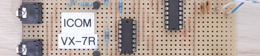
4 Card The ICOM & TEN-TEC Interface Comment ICOM and Ten-Tec both use a carrier-sense multiple access collision detect (CSMA/CD) bus. More than one rig can be attached to this design. Circuit diagram +9~5V DC D N448 P L 00uH 9 C7.0uF L2 00uH J C6.0uF C 47nF + J2 C2 220uF U 78L05 IN COM OUT J3 J4 C3 47nF + L4-2uH -2uH L3 C4 33uF D2 LED C5 00pF R k MAX IC


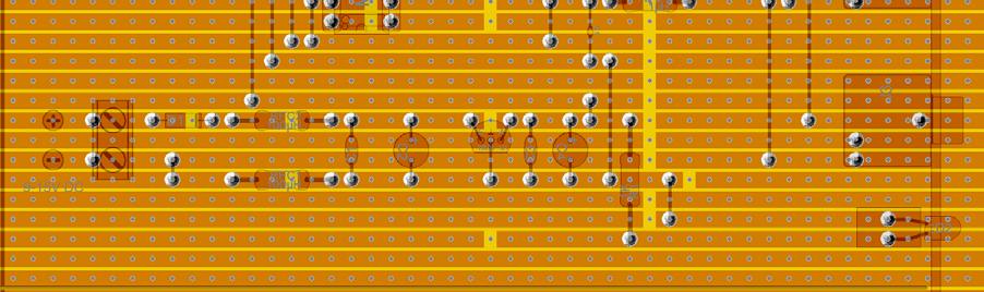
5 The Matrix Board Layout Component side:- Solder side:- 5


6 Component List:- J Screw terminal, double J2 3.5mm Mono jack J3 3.5mm Mono jack J4 3.5mm Mono jack IC DIL20, MAX233CPP SC Socket DIL20 U Voltage regulator, positive 00mA, 78L05 C Ceramic, 47nF C2 Electrolytic capacitor, 220 µf C3 Ceramic, 47nF C4 Electrolytic capacitor, 33µF C5 Ceramic capacitor, 00pF C6 Ceramic, 0nF C7 Ceramic, 0nF R Resistor, K D SI-diode, N448 D2 LED 3mm, red RFC Inductor, 00µH RFC2 Inductor, 00µH RFC3 Inductor, µh RFC4 Inductor, µh Photograph of completed board. 6
7 Card 2 The Yaesu Interface Comment The only difference between this and the ICOM interface is the separation of the RX and TX lines to the rig. Circuit diagram L3-2uH 9 J2 L4-2uH C6 00pF ~5V DC D N448 P2 L 00uH C7.0uF L2 00uH J3 C8.0uF C 47nF + C2 220uF U 78L05 IN COM OUT C3 47nF L5-2uH + C4 33uF D2 LED R k C5 00pF MAX IC


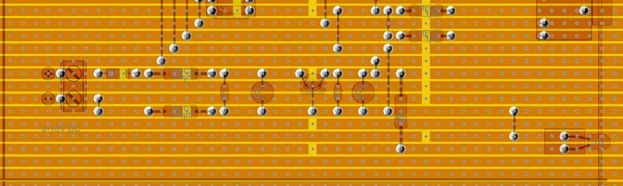
8 The Matrix Board Layout Component side:- Solder side:- 8


9 Component List:- ST Screw terminal, double J 3.5mm Stereo jack IC DIL20, MAX233CPP SC Socket DIL20 U Voltage regulator, positive 00mA, 78L05 C Ceramic, 47nF C2 Electrolytic capacitor, 220 µf C3 Ceramic, 47nF C4 Electrolytic capacitor, 33µF C5 Ceramic, 00pF C6 Ceramic, 00pF C7 Ceramic,.0uF C8 Ceramic,.0uF R Resistor, K D SI-diode, N448 D2 LED 3mm, red RFC Inductor, 00µH RFC2 Inductor, 00µH RFC3 Inductor, µh RFC4 Inductor, µh RFC5 Inductor, µh Photograph of completed board. 9
10 Card 3 The ICOM, TEN-TEC and Yaesu VX-7R Interface Comment Two rigs of the same manufacturer can be attached to this design. The Yaesu handheld is much more demanding than the HF rigs hence the additional amplification and buffering. The transistor pinout is illustrated in the photograph. Circuit diagram U2A R3 D3 k LED2 +9~5V DC D N448 P2 L 00uH 9 C5.0uF L2 00uH J3 C6.0uF C 47nF + C2 220uF U 78L05 IN COM OUT C3 47nF + C4 33uF D2 LED R k MAX IC U2B U2C U2D Q2 NPN R9 0K R8 0K R2 D4 k LED3 R4 0k R6 47K Q NPN R7 47K R5 00K J J2 4 74LS04 IC2 7 0


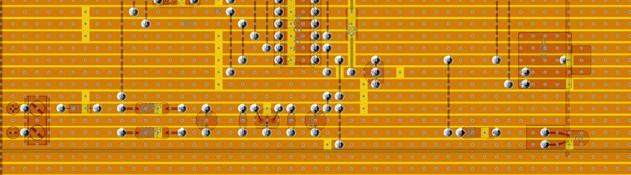
11 The Matrix Board Layout Component side:- Solder side:-

12 Component List:- ST Screw terminal, double IC DIL20, MAX233CPP IC2 DIL4, 74LS04 S U Voltage regulator, positive 00mA, 78L05 C2 Socket DIL4 SC4 Socket DIL20 R Resistor, K R2 Resistor, K R3 Resistor, K R4 Resistor, 0K R5 Resistor, 00K R6 Resistor, 47K R7 Resistor, 47K R8 Resistor, 0K R9 Resistor, 0K Q TO-92, npn 2N3904 Q2 TO-92, npn 2N3904 RFC Inductor, 00µH RFC2 Inductor, 00µH D SI-diode, N448 D2 LED 3mm, red D3 LED 3mm, green D4 LED 3mm, yellow J 3.5mm Stereo jack, PCB C Electrolytic capacitor, 220uF C2 Ceramic, 0.uF C3 Ceramic, 0.uF C4 Electrolytic capacitor, 33µF C5 Ceramic, 0.0uF C6 Ceramic, 0.0nF 2N3904 2
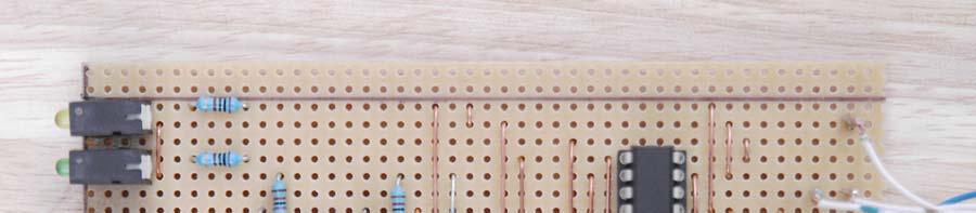
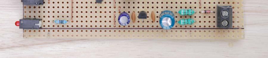
13 Photograph of completed board. 3
14 Card 4 The Kenwood Interface Comment The Kenwood card is at the prototype stage and although a full description is included it has not been fully tested. However, the circuit is known to work. The Kenwood interface differs from the other three in two respects; the logic is active low and RTS and CTS are implemented. The services of a local Kenwood owner are being sought to help with the testing. If anyone is brave enough to build it would they please me their experiences. Circuit diagram U2C Rig RTS C8.0uF U2D U2A Rig CTS Rig RX +9~5V DC C7.0uF D5 N448 P2 L 00uH 9 C5.0uF L2 00uH J C6.0uF C 47nF + C2 220uF U 78L05 IN OUT COM C3 47nF + C4 33uF D2 LED R k MAX IC U2B Rig TX 4 IC2 74HC04 7 4


15 The Matrix Board Layout Component side:- N.B. There are two links on the underside of the board from the mini din plug. Solder side:- 5


16 Component List:- IC DIL20, MAX233CPP IC2 DIL4, 74LS04 U Voltage regulator, positive 00mA, 78L05 SC Socket DIL4 SC2 Socket DIL20 RFC Inductor, 00µH RFC2 Inductor, 00µH D SI-diode, N448 D2 LED 3mm, red ST Screw terminal, double C Electrolytic capacitor, 220uF C2 Ceramic, 47nF C3 Ceramic, 47nF C4 Electrolytic capacitor, 33µF C5 Ceramic, 0nF C6 Ceramic, 0nF C7 Ceramic, 0nF C8 Ceramic, 0nF R Resistor, K Photograph of completed board. 6
17 Boxing the Completed Project The Hammond box used for this project consists of a black anodised aluminium extrusion in a U section with a separate sliding top (bottom) also of aluminium. The sides of the U section include rails to take slide-in circuit boards. The box is closed with thick plastic end plates which are easy to work. Using this enclosure enables the circuit board to be constructed outside the box and slid into place once completed. Consequently, there are no tricky solder connections to be made within the box itself. The only obvious problem is the need to drill very precise holes in the end plate to take the sockets and the LEDs which will pass through it. Fortunately, the solution is simple. Once the board has been constructed select the rails which place the socket and LED where required. Now remember your dentist, but not for long, and take an impression. Making an Impression Fill the end plate with a slab of Blu-Tack leaving about 2mm gap all-round to ease the fit. Push the end cap into place; it need not go fully home as long as it is square to the body of the box. Insert the circuit board in its slot and slowly force the socket and LED into the Blu-Tack. A couple of mm should be sufficient. Very carefully withdraw the circuit board and make sure it does not drag the Blu-Tack with it repeat the process for the second board. You should end up with an impression similar to that in the accompanying photograph. Take a fine bit, say.5mm, and drill a hole at the centre of each of the impressions right through the Blu-Tack and the end plate. Remove the Blu-Tack, enlarge the holes with progressively larger bits, and finish to size with a reamer. Offer up the circuit board once again and you should have a perfect slide-in fit. 7


18 The rear endplate of the box is drilled for grommets taking the two data lines and the power line. Plastic sleeved grommets are used for the data lines. These are placed centrally to avoid any projections on the cards. The power cord is held in place by a gripper-grommet for added security. In addition, all the grommets are secured in place with a few dabs of superglue. Details of the end plate The screw connectors for the 2V supply allow easy interconnections between the two cards. The interconnecting wires are routed through conveniently sited holes in the matrix board from the lower to the upper card. For ease of testing CAT5 cable was used for the data lines with an RJ45 connector plugged into an RS232 converter. The converter is permanently attached to the computer. It is for this reason that RTS and CTS connections are shorted at the board rather than in the RS232 socket. 8
19 Ugly Construction The advantage of matrix board for a constructional article is its reproducibility and ease of diagnosis. Ugly construction is fast, direct and looks a mess but often proves very reliable. To illustrate the process, a self-powered ICOM interface was constructed using the MAX233 chip. The dead bug system of construction was used. A saw and a scalpel were employed to separate out sufficient pads on which to solder the various components. The chip was placed upside down on the copper ground plane and the grounded pins and unused inputs were twisted in a loop back to the ground plane where they were soldered in place. Once they were soldered these pins kept the chip located. The rest of the components (just six) and external connections were added to the assembly by point-to-point wiring. Self-powered ICOM Interface Circuit Diagram D DIODE J D2 DIODE D3 ZENER R 220R + C 33uF J2 C2.0uF MAX Component List:- IC MAX233 C Electrolytic, 33uF C2 Ceramic,.0uF D Diode, IN448 D2 Diode, IN448 D3 Zener, 5.V J Connector, DB9F J2 Connector, 3.5mm Mono Jack R Resistor, 220R 9


20 The completed board Happily, if surprisingly, it worked first time! Clearly, it was necessary to find a suitable cover to hide this chaotic construction from critical view. Meet Lucanus electronicus - Call me Luke! 20
21 Software Simon Brown HB9DRV, assisted by Peter Halpin PHPH, has written some excellent software for controlling rigs. This started with a program for the FT-87 called FT-87 Commander which has been superseded by Ham Radio Deluxe available from This program allows the control of a wide range of rigs. The base station interfaces illustrated here were tested with Ham Radio Deluxe. The Yaesu VX-7R interface was tested using Jim Mitchell s VX-7 Commander available from Sources ARRL Handbook Interfacing a collection of published interfaces by Peter Halpin PHPH:- Hiroto Fukui JF3RFY: Contact If you have any comments, suggestions or general feedback you can contact me by at basil.helman@btopenworld.com. 2
Constructing Two Computer to Rig Interfaces for ICOM, Ten-Tec and Yaesu Radios
 For the West Somerset Amateur Radio Club Constructing Two Computer to Rig Interfaces for ICOM, Ten-Tec and Yaesu Radios by Bas Helman G4TIC Introduction The following two circuits are both based on the
by illumicon OptoCAT Mk2 Pietershoek XA Veldhoven The Netherlands fax
 by illumicon www.ezkits.eu OptoCAT Mk2 Pietershoek 3 5503XA Veldhoven The Netherlands fax +31-40-2230020 Contents Introduction...3 Design Considerations...3 Soldering Tips...3 Assembly...4 Option 1...5
Schematic Diagram: R2,R3,R4,R7 are ¼ Watt; R5,R6 are 220 Ohm ½ Watt (or two 470 Ohm ¼ Watt in parallel)
") Nano DDS VFO Rev_2 Assembly Manual Farrukh Zia, K2ZIA, 2016_0130 Featured in ARRL QST March 2016 Issue Nano DDS VFO is a modification of the original VFO design in Arduino Projects for Amateur Radio by
Nano DDS VFO Rev_2 Assembly Manual Farrukh Zia, K2ZIA, 2016_0130 Featured in ARRL QST March 2016 Issue Nano DDS VFO is a modification of the original VFO design in Arduino Projects for Amateur Radio by
Universal Keying Adapter 3+
 Universal Keying Adapter 3+ The Universal Keying Adapter Version 3+ kit will allow you to key nearly any transmitter or transceiver with a straight key, electronic keyer, computer serial or parallel port
High Power (15W + 15W) Stereo Amplifier
 Stereo Amplifier") High Power (15W + 15W) Stereo Amplifier Build Instructions Issue 1.0 Build Instructions Before you put any components in the board or pick up the soldering iron, just take a look at the Printed Circuit
High Power (15W + 15W) Stereo Amplifier Build Instructions Issue 1.0 Build Instructions Before you put any components in the board or pick up the soldering iron, just take a look at the Printed Circuit
Microsystems. SCI-6 Sound Card Interface Kit Version 1.09 January 2015
 UM Unified Microsystems SCI-6 Sound Card Interface Kit Version 1.09 January 2015 The SCI-6 interface was designed to be a low cost, high quality interface between your PC s sound card and radio transceiver.
The $10* Icom CI-V Computer Interface For Computerized Rig Control or Logging. Utilizing No External Power and all parts from RadioShack.
 The $10* Icom CI-V Computer Interface For Computerized Rig Control or Logging Utilizing No External Power and all parts from RadioShack.com _ Note: On the miniature electrolytics, the negative lead is
solutions for teaching and learning
 RKOneAnalogue Component List and Instructions PCB layout Constructed PCB Schematic Diagram RKOneAnalogue Software Development PCB Page 1 Description The RKOneAnalogue software development PCB has been
Sierra Radio Systems. HamStack. Project Board Reference Manual V1.0
 Sierra Radio Systems HamStack Project Board Reference Manual V1.0 Welcome HamStack Project Board Reference Manual Revision 1.0.3 2011 George Zafiropoulos, KJ6VU and John Best, KJ6K This guide provides
RC Tractor Guy Controller V2.1 Assembly Guide
 RC Tractor Guy Controller V. Assembly Guide Features 0 Push button inputs Dual axis thumb sticks with built-in push button Rotary encoders with built-in push button MCU Socket to suit Meduino Mega 560
DELUXE STEREO AMPLIFIER KIT
 ESSENTIAL INFORMATION BUILD INSTRUCTIONS CHECKING YOUR PCB & FAULT-FINDING MECHANICAL DETAILS HOW THE KIT WORKS CREATE YOUR OWN SPEAKER DOCK WITH THIS DELUXE STEREO AMPLIFIER KIT Version 2.0 Build Instructions
solutions for teaching and learning
 RKAmp1 Component List and Instructions PCB layout Constructed PCB Schematic RKAmp1 Stereo Amplifier Page 1 Description The RKAmp1 stereo amplifier PCB has been designed around the 2 x 1watt stereo amplifier
BATC Kit MTK2 for MiniTiouner
 BATC Kit MTK2 for MiniTiouner Serit FTS4335V NIM Converter Document Change Log 2017-02-22 v1.01 First release 2017-03-01 v1.04 Minor mods Serit FTS4335V, Converter and MiniTiouner (built by G4KLB) Serit
MP3 audio amplifier. Build Instructions. Issue 2.0
 MP3 audio amplifier Build Instructions Issue 2.0 Build Instructions Before you put any components in the board or pick up the soldering iron, just take a look at the Printed Circuit Board (PCB). The components
Modular Backplane For RC2014 User Guide
 Modular Backplane For RC204 User Guide For module: SC2 version.0 Design and Documentation by Stephen C Cousins Edition.0. CONTENTS OVERVIEW...2 PRINTED CIRCUIT BOARD... 4 SCHEMATIC... 8 WHAT YOU NEED...9
solutions for teaching and learning
 RKAmp3 Component List and Instructions PCB layout Constructed PCB Schematic RKAmp3 Stereo Amplifier Page 1 Description The RKAmp3 stereo amplifier PCB has been designed around the 2 x 7watt stereo amplifier
Voice Keyer Kit by DH8BQA (BX-184)
") Voice Keyer Kit by DH8BQA (BX-184) 2011 5 24 1 Quick assembly guide Most amateur radios do not have an internal voice memory for transmitting. If you want to use such a convenient feature you can build
Voice Keyer Kit by DH8BQA (BX-184) 2011 5 24 1 Quick assembly guide Most amateur radios do not have an internal voice memory for transmitting. If you want to use such a convenient feature you can build
SharpSky Focuser Construction. SharpSky Focuser. Construction Document V st December 2012 Dave Trewren 1
 SharpSky Focuser Construction Document V0.12 1st December 2012 Dave Trewren 1 Contents 1 General... 3 1.1 Change Record... 3 1.2 References... 3 2 Introduction... 5 3 SharpSky driver installation... 5
Shack Clock kit. U3S Rev 2 PCB 1. Introduction
 Shack Clock kit U3S Rev 2 PCB 1. Introduction Thank you for purchasing the QRP Labs Shack Clock kit. This clock uses the Ultimate3S QRSS/WSPR kit hardware, but a different firmware version. It can be used
TKEY-1. CW touch key. (no electromechanical contacts) Assembly manual. Last update: June 20,
 Assembly manual. Last update: June 20,") TKEY-1 CW touch key (no electromechanical contacts) Assembly manual Last update: June 20, 2017 ea3gcy@gmail.com Updates and news at: www.ea3gcy.com Thanks for constructing the TKEY-1A CW touch key Have
TKEY-1 CW touch key (no electromechanical contacts) Assembly manual Last update: June 20, 2017 ea3gcy@gmail.com Updates and news at: www.ea3gcy.com Thanks for constructing the TKEY-1A CW touch key Have
Installing a LIF port into the IC-703 transceiver
 Installing a LIF port into the IC-703 transceiver Introduction This document describes the procedure for installing a LIF (Low Intermediate Frequency [9 18kHz]) port into the FT-950 transceiver. This procedure
Button Code Kit. Assembly Instructions and User Guide. Single Button Code Entry System
 Button Code Kit Single Button Code Entry System Assembly Instructions and User Guide Rev 1.0 December 2009 www.alan-parekh.com Copyright 2009 Alan Electronic Projects Inc. 1. Introduction... 4 1.1 Concept
Building and using JasperMIDI
 Building and using JasperMIDI Table of Contents Introduction... Bill Of Materials... 2 Building Choices... 3 Construction... 4 Installing in a Jasper enclosure... 5 Standalone use... 6 Using JasperMIDI...
IR TRANSMITTER BLOK PCB ASSEMBLY INSTRUCTIONS. Copyright EduTek Ltd Rev. 2
 IR TRANSMITTER BLOK PCB ASSEMBLY INSTRUCTIONS Copyright EduTek Ltd Rev. 2 Circuit Details The circuit is shown below with a parts list of components. Check through this list and identify each component.
solutions for teaching and learning
 RKP18Motor Component List and Instructions PCB layout Constructed PCB Schematic Diagram RKP18Motor Project PCB Page 1 Description The RKP18Motor project PCB has been designed to use PIC microcontrollers
RC210 Repeater Controller Assembly Manual
 Arcom Communications 24035 NE Butteville Rd Aurora, Oregon 97002 (503) 678-6182 arcom@ah6le.net http://www.arcomcontrollers.com/ RC210 Repeater Controller Assembly Manual Hardware Version 3.3 Reproduction
Assembly Instructions (8/14/2014) Your kit should contain the following items. If you find a part missing, please contact NeoLoch for a replacement.
 Your kit should contain the following items. If you find a part missing, please contact NeoLoch for a replacement.") NeoLoch NLT-28P-LCD-5S Assembly Instructions (8/14/2014) Your kit should contain the following items. If you find a part missing, please contact NeoLoch for a replacement. Kit contents: 1 Printed circuit
NeoLoch NLT-28P-LCD-5S Assembly Instructions (8/14/2014) Your kit should contain the following items. If you find a part missing, please contact NeoLoch for a replacement. Kit contents: 1 Printed circuit
Installation/assembly manual for DCC/Power shield
 Installation/assembly manual for DCC/Power shield The DCC circuit consists of the following components: R1/R6 R2/R3 R4/R5 D1 C2 2 kω resistor ½ Watt (colour code Red/Black/Black/Brown/Brown) 10 kω resistor
Images Scientific OWI Robotic Arm Interface Kit (PC serial) Article
 Article") Images Scientific OWI Robotic Arm Interface Kit (PC serial) Article Images Company Robotic Arm PC Interface allows real time computer control and an interactive script writer/player for programming and
Images Scientific OWI Robotic Arm Interface Kit (PC serial) Article Images Company Robotic Arm PC Interface allows real time computer control and an interactive script writer/player for programming and
PICAXE EXPERIMENTER BOARD (AXE090)
") (AXE00) Description: The PICAXE experimenter board allows circuits for any size/revision of PICAXE chip ( / / ) to be quickly tested using a prototyping breadboard. The experimenter board provides power
(AXE00) Description: The PICAXE experimenter board allows circuits for any size/revision of PICAXE chip ( / / ) to be quickly tested using a prototyping breadboard. The experimenter board provides power
by illumicon APRSTRACKER Pietershoek XA Veldhoven The Netherlands fax
 by illumicon www.ezkits.eu APRSTRACKER Pietershoek 3 5503XA Veldhoven The Netherlands fax +31-40-2230020 Contents Introduction...3 Soldering Tips...3 Assembly...4 Schema...5 Connections...6 Adjustments...6
You need the following components to assemble the Black n Wood Nixie Clock circuit board:
 You need the following components to assemble the Black n Wood Nixie Clock circuit board: Quantity Designator Description 1 Battery Battery, CR1220 1 Battery Battery holder 3 Button 1, Button 2, Button
These are the illustrated step-by-step guidelines for upgrading your Quad 306 with the Dada Electronics upgrade-kit.
 Quad 306 DIY illustrated guidelines version 1.1 These are the illustrated step-by-step guidelines for upgrading your Quad 306 with the Dada Electronics upgrade-kit. We will replace all electrolytic capacitors,
Pacific Antenna Easy TR Switch Kit
 Pacific Antenna Easy TR Switch Kit Kit Description The Easy TR Switch is an RF sensing circuit with a double pole double throw relay that can be used to automatically switch an antenna between a separate
Cumbria Designs T-1. C-1 Controller. User Manual
 Cumbria Designs T-1 C-1 Controller User Manual CONTENTS 1 INTRODUCTION 2 2 CIRCUIT DESCRIPTION 2 3 ASSEMBLY 3 4 CONNECTIONS AND CONFIGURATION 4 5 TESTING 6 Appendix A C-1 Circuit Diagram and PCB Component
Ultimate LPF kit: Relay-switched LPF kit
 Ultimate LPF kit: Relay-switched LPF kit PCB Revision 4 1. Introduction Thank you for purchasing the QRP Labs relay-switched low-pass filter (LPF) kit. This kit is designed to complement the Ultimate3
Pacific Antenna Two Tone Generator
 Pacific Antenna Two Tone Generator Description Our Two Tone Generator kit provides two non-harmonic, sine wave signals for testing audio circuits Outputs of approximately 700Hz and 1900Hz and the combination
MAIN PCB (The small one)
") THANKS FOR CHOOSING ONE OF OUR KITS! This manual has been written taking into account the common issues that we often find people experience in our workshops. The order in which the components are placed
THANKS FOR CHOOSING ONE OF OUR KITS! This manual has been written taking into account the common issues that we often find people experience in our workshops. The order in which the components are placed
Uzebox Kit Assembly Guide
 Uzebox Kit Assembly Guide V1.3 Page 1 of 18 Revision History Version Date Author Description 1.0 01-Nov-2012 A.Bourque Initial release 1.1 6-Nov-2012 A.Bourque Minor corrections 1.2 28-Jan-2014 A.Bourque
IQ32 Upgrade Kit Assembly Instructions
 IQ32 Upgrade Kit Assembly Instructions Jim Veatch WA2EUJ September 17, 2018 TABLE OF CONTENTS 1. INTRODUCTION... 3 2. IQ-32 UPGRADE KIT INVENTORY... 4 3. PREPARING THE RS-HFIQ AND SIDE PANELS... 6 4. CONNECTING
PICAXE CONNECT (AXE210)
") PICAXE CONNECT (AXE10) Description: The AXE10 Connect board has been designed as a experimental project board for users wishing to learn how to interface a PICAXE chip to the Maxstream module or a LocSense
PICAXE CONNECT (AXE10) Description: The AXE10 Connect board has been designed as a experimental project board for users wishing to learn how to interface a PICAXE chip to the Maxstream module or a LocSense
Chill Interface PCB Assembly Instructions
 ExcelValley Chill Interface PCB Waveblaster Module MIDI Interface Board Chill Limited Edition V2 Assembly Kit Standalone midi interface board for Waveblaster synthesizer modules. Suitable for most Waveblaster
RKP08 Component List and Instructions
 RKP08 Component List and Instructions PCB layout Constructed PCB RKP08 Scematic RKP08 Project PCB Page 1 Description The RKP08 project PCB has been designed to use PIC microcontrollers such as the Genie
PicoTurbine Mark 8.3 Generator Field Controller Kit
 PicoTurbine Mark 8.3 Generator Field Controller Kit Based on a design published in Home Power magazine by Richard Perez. Used with permission. Reprint of original article included with kit. An easy-to-build
3-slot Backplane For RC2014 User Guide
 3-slot Backplane For RC204 User Guide For module: SC6 version.0 Design and Documentation by Stephen C Cousins Edition.0.0, 208-0-7 CONTENTS OVERVIEW...2 PRINTED CIRCUIT BOARD... 4 SCHEMATIC... 6 WHAT YOU
Deep Vibes. Wobbly Optical Vibe action
 Deep Vibes Wobbly Optical Vibe action Contents of this document are 2018 Pedal Parts Ltd. No reproduction permitted without the express written permission of Pedal Parts Ltd. All rights reserved. Important
Sierra Radio Systems. Digital Compass. Reference Manual. Version 1.0
 Sierra Radio Systems Digital Compass Reference Manual Version 1.0 Contents Digital compass board RS485 power injector For more information, go to the Sierra Radio Systems web site at www.sierraradio.net
RC-210 Repeater Controller Assembly Manual
 Arcom Communications 24035 NE Butteville Rd Aurora, Oregon 97002 (503) 678-6182 arcom@ah6le.net RC-210 Repeater Controller Assembly Manual Hardware Version 2.5 Reproduction or translation of any part of
The Sudden Storm Kit. by QRPme. Builder s Guide. version4.2. for. Sudden Storm ][ Ver4 (red pcb) Updated 01/10/2012
![The Sudden Storm Kit. by QRPme. Builder s Guide. version4.2. for. Sudden Storm ][ Ver4 (red pcb) Updated 01/10/2012](/thumbs/75/72448638.jpg "The Sudden Storm Kit. by QRPme. Builder s Guide. version4.2. for. Sudden Storm ][ Ver4 (red pcb) Updated 01/10/2012") The Sudden Storm Kit by QRPme Builder s Guide version4.2 for Sudden Storm ][ Ver4 (red pcb) Updated 01/10/2012 Open the can and the adventure begins 1 Organize the parts and take an inventory Bill of Materials
The Sudden Storm Kit by QRPme Builder s Guide version4.2 for Sudden Storm ][ Ver4 (red pcb) Updated 01/10/2012 Open the can and the adventure begins 1 Organize the parts and take an inventory Bill of Materials
PowerAmp Design. PowerAmp Design EVAL127 EVALUATION KIT FOR PAD127/157. Rev G
 PowerAmp Design EVALUATION KIT FOR PAD7/57 EVAL7 Rev G INTRODUCTION The EVAL7 assembled evaluation kit provides a convenient method to become familiar with the operation of the PAD7/57 operational amplifiers
Rapid28iXL PIC Prototyping PCB User Manual
 Description Features This is a PCB designed to facilitate the rapid prototyping of a device based on a 28 pin Microchip PIC microcontroller. To allow users to focus on their application, we take care of
EE 354 August 1, 2017 Assembly of the AT89C51CC03 board
 EE 354 August 1, 2017 Assembly of the AT89C51CC03 board The AT89C51CC03 board comes as a kit which you must put together. The kit has the following parts: No. ID Description 1 1.5" x 3.25" printed circuit
Part 2: Building the Controller Board
 v3.01, June 2018 1 Part 2: Building the Controller Board Congratulations for making it this far! The controller board uses smaller components than the wing boards, which believe it or not, means that everything
PowerAmp Design EVAL117 EVALUATION KIT FOR PAD117A
 EVALUATION KIT FOR PAD117A INTRODUCTION The EVAL117 evaluation kit provides a convenient method to become familiar with the operation of the PAD117A operational amplifier before your application circuit
Assembly Instructions for the KA Electronics Elliptic Equalizer
 Assembly Instructions for the KA Electronics Elliptic Equalizer Install IC sockets Elliptic Equalizer PC Board Stuffing Guide Place the PC Board on the work bench silkscreen side face up. Place twelve
RECORD & PLAYBACK KIT
 ESSENTIAL INFORMATION BUILD INSTRUCTIONS CHECKING YOUR PCB & FAULT-FINDING MECHANICAL DETAILS HOW THE KIT WORKS ADD AN AUDIO MESSAGE TO YOUR PRODUCT WITH THIS RECORD & PLAYBACK KIT Version 2.1 Build Instructions
Rapid40iXL PIC Prototyping PCB User Manual
 Description This is a PCB designed to facilitate the rapid prototyping of a device based on a 40 pin Microchip PIC microcontroller. To allow users to focus on their application, we take care of key housekeeping
Modular Backplane For RC2014 User Guide
 Modular Backplane For RC2014 User Guide For module: SC113 version 1.1 Design and Documentation by Stephen C Cousins Edition 1.1.0 CONTENTS OVERVIEW...2 PRINTED CIRCUIT BOARD... 4 SCHEMATIC... 8 WHAT YOU
WinKey V6 PCB Assembly Guide Version /4/2013
 WinKey V6 PCB Assembly uide Version.4 2/4/203 This document describes the assembly, checkout, and hook up of the KEL Winkey2 Serial Kit with a version V6 PCB. This design is powered directly off the PC
RDS MAX V2.0. PCS Electronics
 PCS Electronics www.pcs-electronics.com info@pcs-electronics.com RDS MAX V2.0 Many customers have requested RDS encoder in the past. RDS MAX v2.0 is our first RDS encoder, a slightly improved version of
K8099 NIXIE CLOCK. * optional enclosure TKOK19 (black) - TKOK17 (white) ** optional plexiglass enlcosure B8099 ILLUSTRATED ASSEMBLY MANUAL
 - TKOK17 (white) ** optional plexiglass enlcosure B8099 ILLUSTRATED ASSEMBLY MANUAL") Total solder points: 230 + 74 Difficulty level: beginner 1 2 3 4 5 advanced NIXIE CLOCK K8099 ** * A unique combination of both vintage and modern electronics ILLUSTRATED ASSEMBLY MANUAL H8099IP-1 * optional
Total solder points: 230 + 74 Difficulty level: beginner 1 2 3 4 5 advanced NIXIE CLOCK K8099 ** * A unique combination of both vintage and modern electronics ILLUSTRATED ASSEMBLY MANUAL H8099IP-1 * optional
MICRO-TRAK 300 MANUAL VER 1.4
 MICRO-TRAK 300 MANUAL VER 1.4 The Micro-Trak 300 Version 1.4 is a miniature APRS (Automatic Position Reporting System) transmitter operating on the North American APRS frequency standard of 144.390 MHz.
RC-210 Repeater Controller Assembly Manual
 Arcom Communications 24035 NE Butteville Rd Aurora, Oregon 97002 (503) 678-6182 arcom@ah6le.net RC-210 Repeater Controller Assembly Manual Hardware Version 3.0 Original Release Date September 13, 2004
Cherub Chorus. Wobbly fun based on Rick Holt s Little Angel
 Cherub Chorus Wobbly fun based on Rick Holt s Little Angel Contents of this document are 2015 Pedal Parts Ltd. No reproduction permitted without the express written permission of Pedal Parts Ltd. All rights
Building the Super-VMW CPU Meter by Vincent M. Weaver 18 May 2011
 Building the Super-VMW CPU Meter http://www.deater.net/weave/vmwprod/meter/super.html by Vincent M. Weaver 18 May 2011 1 Parts List Part No Description Quantity Source LED Board 1 SVMW-Meter-LED-Board
Quicksilver 606 TR-606 CPU Upgrade
 Quicksilver 606 TR-606 CPU Upgrade D650C 128 Installation Guide Social Entropy Electronic Music Instruments TABLE OF CONTENTS WARNINGS... 1 OVERVIEW... 2 WHAT'S IN THE BOX... 3 OPENING THE TR-606 CASE...
Introduction 1. Liquid crystal display (16 characters by 2 rows) Contrast dial: turn the dial to adjust the contrast of the display (see page 5)
 Contrast dial: turn the dial to adjust the contrast of the display (see page 5)") Welcome to the GENIE Serial LCD module. Introduction 1 The GENIE Serial LCD module allows GENIE-based projects to display messages on a 16 character by 2 row liquid crystal display (LCD). This worksheet
Welcome to the GENIE Serial LCD module. Introduction 1 The GENIE Serial LCD module allows GENIE-based projects to display messages on a 16 character by 2 row liquid crystal display (LCD). This worksheet
LED Knight Rider. Yanbu College of Applied Technology. Project Description
 LED Knight Rider Yanbu College of Applied Technology Project Description This simple circuit functions as a 12 LED chaser. A single illuminated LED 'walks' left and right in a repeating sequence, similar
Assembly Instructions for the KA Electronics RIAA EQ Monitor Switcher
 Assembly Instructions for the KA Electronics RIAA EQ Monitor Switcher Install IC sockets EQ Monitor Switcher PC Board Stuffing Guide Place the PC Board on the bench silkscreen side face up. Drop eleven
QUASAR PROJECT KIT # ATMEL AVR PROGRAMMER
 This kit is a simple but powerful programmer for the Atmel AT90Sxxxx ( AVR ) family of microcontrollers. The Atmel AVR devices are a low-power CMOS 8-bit microcontroller using a RISC architecture. By executing
Storage Card Interface Kit
 Storage Card Interface Kit for MultiMediaCards(MMC) and Secure Digital Cards (SD) MMSD3K The MMSD3K is complete development kit interfaced to a SD or MMC card. This board ideal for projects that involve
Arduino shield kit. 1) Low Pass Filter (LPF) kit (available for LF/MF/HF/VHF bands 2,200m to 6m)
 Low Pass Filter (LPF) kit (available for LF/MF/HF/VHF bands 2,200m to 6m)") Arduino shield kit 1. Introduction The QRP Labs Arduino shield kit is a versatile shield that can be used for various purposes. Write your own Arduino sketch to define the functionality! For example: 1)
Arduino shield kit 1. Introduction The QRP Labs Arduino shield kit is a versatile shield that can be used for various purposes. Write your own Arduino sketch to define the functionality! For example: 1)
Single cable kit for the FCB1010
 Single cable kit for the FCB1010 1. What is it? With this kit, you can turn your FCB1010 into a phantom powered floorboard, which can do 2-way MIDI communication over one single cable. After installing
Modular Backplane For RC2014 User Guide
 Modular Backplane For RC204 User Guide For module: SC05 version.0 Design and Documentation by Stephen C Cousins Edition.0.0 CONTENTS OVERVIEW...2 PRINTED CIRCUIT BOARD... 4 SCHEMATIC... 6 WHAT YOU NEED...7
Effects Loop Installation Guide
 Warnings and Disclaimer Effects Loop Installation Guide You will be working with HIGH VOLTAGE. These voltages CAN BE DEADLY if you are not extremely careful. If you are not comfortable working with HIGH
Shack Clock kit PCB Revision: QCU Rev 1 or QCU Rev 3
 1. Introduction Shack Clock kit PCB Revision: QCU Rev 1 or QCU Rev 3 Thank you for purchasing this QRP Labs Shack Clock kit. The kit uses the same PCB and bag of components as some other QRP Labs kits.
SRI-02 Speech Recognition Interface
 SRI-02 Speech Recognition Interface Data & Construction Booklet The Speech Recognition Interface SRI-02 allows one to use the SR-07 Speech Recognition Circuit to create speech controlled electrical devices.
Uzebox Kit Assembly Guide
 Uzebox Kit Assembly Guide V1.7 Page 1 of 21 Revision History Version Date Author Description 1.0 01-Nov-2012 A.Bourque Initial release 1.1 6-Nov-2012 A.Bourque Minor corrections 1.2 28-Jan-2014 A.Bourque
DSP-232 Upgrade Kit A.06113
 DSP-232 Upgrade Kit A.063 Installation and Operation Manual Rev. 2.0 WARRANTY WHO IS COVERED WHAT WE WILL DO WHAT YOU MUST DO WHAT IS NOT COVERED SERVICE WARRANTY HOW TO CONTACT TIMEWAVE TIMEWAVE TECHNOLOGY
Mini B lue M idnight
 Mini Blue Midnight 2011 by Shattered Glass Audio. All rights reserved. No part of this document may be reproduced or transmitted in any form or by any means, electronic, mechanical, photocopying, recording,
dual bipolar voltage controlled step sequencer DIY ASSEMBLY MANUAL v1.03
 dual bipolar voltage controlled step sequencer DIY ASSEMBLY MANUAL v1.03 Contents Contents... 2 Introduction... 3 Part Sourcing Notes for Non Kit Builders... 3 Eurorack Kit Assembly... 4 Resistors and
StationPro II Network Manual rev. 06/27/2010
 StationPro II Network Manual rev. 06/27/2010 The StationPro system is designed so that two or three of the SP- II units can be networked together, allowing a total of nine radios and nine amplifiers to
SM010, Assembly Manual PCB Version 1.0
 180 SM010, Assembly Manual MATRIXARCHATE 16 8 IO SEQUENTIAL MATRIX SIGNAL ROUTER SM010 1 2 1 2 3 4 5 3 4 5 6 7 8 9 10 11 12 6 7 8 9 10 11 12 13 14 15 16 PROGRAM A B C D E F G H f1 f2 20.000 180 SSSR Labs
BS2p40tm OEM Module. Surface mount/through hole kit By Robert L. Doerr. Manual Revision.5
 BS2p40tm OEM Module Surface mount/through hole kit 2006 By Robert L. Doerr Manual Revision.5 NOTE: The BASIC Stamp and the BS2p40 and Interpreter chip are trademarks of Parallax. This partial kit allows
Solder the Harlequin, Revision F, March Solder the Harlequin - please read carefully (also the addendum!) before starting
 before starting") Solder the Harlequin, Revision F, March 2014 Page 1 of 8 Solder the Harlequin - please read carefully (also the addendum!) before starting You should check the kit for completeness (see addendum). If you
Solder the Harlequin, Revision F, March 2014 Page 1 of 8 Solder the Harlequin - please read carefully (also the addendum!) before starting You should check the kit for completeness (see addendum). If you
Electronics Construction Manual
 Electronics Construction Manual MitchElectronics 2018 Version 1 07/05/2018 www.mitchelectronics.co.uk CONTENTS Introduction 3 How To Solder 4 Resistors 5 Capacitors 6 Diodes and LEDs 7 Switches 8 Transistors
Breakout Card For Z50Bus User Guide
 Breakout Card For Z50Bus User Guide For card: SC117 version 1.0 Design and Documentation by Stephen C Cousins Edition 1.0.0 CONTENTS OVERVIEW...2 PRINTED CIRCUIT BOARD... 4 SCHEMATIC... 5 WHAT YOU NEED...6
TH E FI N EST I N G E E K E NTE RTAI N M E NT
 HACKING the C a b l e M o d e m W h at c a b l e c o m pa n i e s d o n t wa n t yo u t o k n o w DerEngel BUILDING A CONSOLE CABLE The device shown in Figure 17-1 is an RS-232 to TTL converter board,
HARDWARE OPERATIONS MANUAL
 HARDWARE OPERATIONS MANUAL Table of Contents INTRODUCTION... 2 SECTION 1: HARDWARE COMPONENT ASSEMBLIES... 2 MECHANICAL HARDWARE AND CASE... 2 PCB ASSEMBLY... 4 ISD RECORDING CIRCUIT... 5 BREADBOARD ASSEMBLY...
GLiPIC Ver C Assembly manual Ver 1.0
 GLiPIC Ver C Assembly manual Ver 1.0 Last Rev 1.1 Oct 30, 2001 Author: Ranjit Diol Disclaimer and Terms of Agreement As with any kit, only the individual parts supplied are guaranteed against defects and
EchoBlue Delay. PT2399 Delayayayayayay v3.0
 EchoBlue Delay PT2399 Delayayayayayay v3.0 Contents of this document are 2015 Pedal Parts Ltd. No reproduction permitted without the express written permission of Pedal Parts Ltd. All rights reserved.
Morse Code Practice Oscillator
 Features Description Keyer speed range: Limited only by keying source True Sine wave tone output Tone Volume Control Tone Frequency Control Internal Speaker 1/8 External Speaker/Headphone Jack RCA Key
ES-362U PRESETTABLE MASTER TIMER
 142 SIERRA ST., EL SEGUNDO, CA 90245 USA (310)322-2136 FAX (310)322-8127 www.ese-web.com ES-362U PRESETTABLE MASTER TIMER OPERATION AND MAINTENANCE MANUAL The ES-362U is a four digit, presettable 100 minute
Storage Card Interface Kit
 Storage Card Interface Kit for MultiMediaCards(MMC) and Secure Digital Cards (SD) MMSD3F The MMSD3K is complete development kit interfaced to a SD or MMC card. This board ideal for projects that involve
KPIC-0818P (V050919) Devices Included in this Data sheet: KPIC-0818P
 Devices Included in this Data sheet: KPIC-0818P") Devices Included in this Data sheet: KPIC-0818P Features: Carefully designed prototyping area Accepts 8 pin PIC12 series micro-controllers Accepts 14 and 18 Pin PIC16 series Accepts some 8,14 and 18 pin
Devices Included in this Data sheet: KPIC-0818P Features: Carefully designed prototyping area Accepts 8 pin PIC12 series micro-controllers Accepts 14 and 18 Pin PIC16 series Accepts some 8,14 and 18 pin
Tone Bender Mk III. Grandaddy of super-cool vintage fuzz tone
 Tone Bender Mk III Grandaddy of super-cool vintage fuzz tone Contents of this document are 2014 Pedal Parts Ltd. No reproduction permitted without the express written permission of Pedal Parts Ltd. All
QRPGuys Digital Dial/Frequency Counter
 QRPGuys Digital Dial/Frequency Counter First, familiarize yourself with the parts and check for all the components. If a part is missing, please contact us and we will send one. You must use qrpguys.parts@gmail.com
LLIA90 LED ARRAY 90 LED Array Illuminator. LLIA90 LED Illuminator Array
 LLIA90 LED Illuminator Array The LLIA90 is a high-quality and high-performance multi-purpose LED illuminator array. It has a built-in regulator and a photocell control circuit for automatic LED array on/off
Electronics Construction Manual
 Electronics Construction Manual MitchElectronics 2019 Version 3 04/02/2019 www.mitchelectronics.co.uk CONTENTS Introduction 3 How To Solder 4 Resistors 5 Capacitors 6 Diodes and LEDs 7 Switches 8 Transistors
Fuzz Rite V2.0. Mosrite FuzzRite / Gus Rite Fuzz
 Fuzz Rite V2.0 Mosrite FuzzRite / Gus Rite Fuzz Contents of this document are 2016 Pedal Parts Ltd. No reproduction permitted without the express written permission of Pedal Parts Ltd. All rights reserved.