Manual FC 3500 DC Fan Control
|
|
|
- Darrell Richard
- 5 years ago
- Views:
Transcription


1 Manual FC 3500 DC Fan Control Description: FC 3500 DC Type: Manual File: Do FC 3500 DC V12 EN.docx VDH Products BV Pages: By: Initials: 23 BVDB Doc.no: Version: Date:
2 Table of contents 1 Introduction Overview FC 3500 DC System Warning Safety Instructions Electric Shock Prevention Fire Prevention Injury Prevention Additional Instructions Technical Data Installation Unpacking the FC 3500 DC unit Installation of the FC 3500 DC Control Switching the control-unit on or off Adjusting the temperature set point Adjusting the fan speed Adjusting the fan speed without temperature control Viewing other measurements Programming Parameters Parameter table Night temperature offset (P70) Error codes Trouble shooting Installation Connection FC 3500 DC drawing w Block diagram FC 3500 DC drawing w Dimensions FC 3500 DC Appendix-A: FC 3500 BP display panel Page 2 of 23


3 1 Introduction This document describes the working and control of the Heinen & Hopman FC 3500 DC. The system can consist of the following parts: 1) FC 3500 DC: Main Panel 2) FC 3500 BP: Display-unit several types (Four button control) 3) FC500-sens: Temperature sensors (Water- Air- en Outside-sensor) 4) RH95-2: Humidity sensor (For Humidity control see Parm.35). 1.1 Overview FC 3500 DC System Page 3 of 23
4 1.2 Warning It is highly recommended to study the operation of the FC 3500 DC Fan Control system carefully before using it. Disclaimer The information contained in this document is assumed to be accurate. However VDH Products BV accepts no liability for any mistakes or errors. Copyright Notice Copyright 2015 VDH Products BV, Roden The Netherlands. No part of this document may be reproduced without the prior written permission of VDH Products BV. Edition v1.0 1st pre-release edition v1.1 changed frontview and connections to general v1.2 changed connections Page 4 of 23

5 2 Safety Instructions 2.1 Electric Shock Prevention WARNING While power is on or when the FC 3500 DC is running, do not open the top cover of the housing. You may get an electric shock. Do not run the FC 3500 DC with the top-cover removed. Otherwise, you may access the exposed high-voltage parts and get an electric shock. Before starting wiring or inspection, switch power off, wait for more than 1 minutes. Ground the FC 3500 DC. Any person who is involved in the wiring or inspection of this equipment should be fully competent to do the work. Always install the FC 3500 DC before wiring. Otherwise you may get an electric shock or be injured. Operate only with dry hands to prevent an electric shock or be injured. Do not subject the cables to scratches, excessive stress, heavy loads or pinching. Otherwise, you may get an electric shock. Do not change anything while power is on. It is dangerous to change while the power is on. 2.2 Fire Prevention CAUTION Mount the FC 3500 DC on an incombustible surface. Installing the equipment directly on or near a combustible surface could lead to a fire. If the FC 3500 DC has become faulty, switch off the FC 3500 DC power. Mount the FC 3500 DC in ventilated area s only. 2.3 Injury Prevention CAUTION Apply only the voltage specified in the instruction manual to each terminal to prevent damage. Ensure that the cables are connected to the correct terminals. Otherwise, damage may occur. Always make sure that polarity is correct to prevent damage. Page 5 of 23
6 2.4 Additional Instructions Also note the following points to prevent an accidental failure, injury, electric shock, etc. Transportation and Installation CAUTION Ensure that installation position and material can withstand the weight of the FC 3500 DC. Install according to the information in the Instruction Manual. Do not operate if the FC 3500 DC is damaged or has parts missing. Do not stand or rest heavy objects on the FC 3500 DC. Prevent screws, wire fragments or other conductive bodies or oil or other flammable substance from entering the FC 3500 DC. Place during installation a covering plate over the FC 3500 DC to prevent metal powder, from drilling activity, being fallen into the unit. Remove covering plate always after finishing installation otherwise, it will give a negative effect on the ventilation of the unit. And the unit can even be overheated by it. Do not drop the FC 3500 DC or subject it to impact. Use the FC 3500 DC under the environmental conditions given in the technical data. Wirring CAUTION Use only cables and wiring capable of withstanding temperatures of 70 O C. It is recommended to use insulation-sleeved solderless terminals for power supply, heater, valve and fan wiring. Connect wires only when the unit is switched off. Any person who is involved in the wiring or inspection of this equipment should be fully competent to do the work. Check if the nominal supply voltage from the FC 3500 DC is equal to the AC-supply voltage. A incorrect power supply voltage can lead to fire, injury or failure. Place interrupters, capable of switching off frequency controllers, like automatic-mccbfuses, between the power supply and the FC 3500 DC and take other safety actions to prevent short-circuit in the external wiring. If no safety action is installed, this can lead to fire, injury or failure. Take care for correct wiring which is firmly mounted otherwise measurement mismatch, injury or damage to the unit can occur. Do not connect a AC supply to the outputs terminals of fan, heater or water valve. This can lead to damage or failure of the unit. Page 6 of 23
7 WARNING Do not attach signal-data cables (display, RS485, sensors, I/O, etc.) to live cables, antenna cables or cables with interference signals. Distance between signal-data cables and cables with interference should be more than 30cm but the absolute minimum should be 10cm. Better is to have separate cable channels for signal-data cables and cables with interference signals (Cable channels with separation must be in full metal). Trial Run CAUTION Check all parameters, and ensure that the machine will not be damaged by a sudden startup. Emergency Stop CAUTION Provide a safety backup such as an emergency brake which will prevent the machine and equipment from hazardous conditions if the FC 3500 DC fails. Operation WARNING Do not modify the equipment The electronic over-current protection does not guarantee protection of the motor from overheating. Do not use a magnetic contactor on the FC 3500 DC input for frequent starting/stopping of the FC 3500 DC. Before changing the settings of the FC 3500 DC fully examine the performances of the motor. Before running a FC 3500 DC which had been stored for a long period, always perform inspection and test operation. For a good performance the FC 3500 DC must be installed in a room which is not applied to extreme temperature changes. When the FC 3500 DC is mounted in a closed switchboard panel this panel should have a cooling fan or airco to provide an ambient temperature of maximum 40 o C. The case temperature of the FC 3500 DC may be 30/C higher than the ambient temperature. Page 7 of 23
 test on the control circuit of the FC 3500 DC.")
8 Maintenance, Inspection and Parts Replacement CAUTION Check the environment of the FC 3000 DC regularly, to obtain good working conditions. Do not carry out a megger (insulation resistance) test on the control circuit of the FC 3500 DC. Replace parts only when the FC 3500 DC is switched off, wait 10 minutes and then open up the unit to replace the needed part. Disposing of the unit Treat as industrial waste. CAUTION General instructions CAUTION Many of the drawings and diagrams in this manual show the FC 3500 DC without a cover, or partially open. Never operate the unit like this. Always replace the cover and follow this manual when operating the FC 3500 DC. Page 8 of 23
9 3 Technical Data FC 3500 DC Description Comment Power supply voltage Power consumption On/Off switch before FC 3500 DC Electronics fuse Water valve output J1: 90Vac.. 260Vac, 50/60Hz 34,5 VA 1,5mm2 (14 AWG) flexible or solid wirring stripped 9mm. F1: 315 ma / 250Vac Slow J20: Triac output 90Vac.. 260Vac 50/60Hz, Max. 1A F2: 1 Amp./250Vac Slow Internal fuse F2 Alarm relay output J5: SPDT contact, max. 8A/250Vac or 5A/30Vdc Dimensions FC 3500 DC Fan Control FC 3500 BP Display unit Temperature ranges Set point Air Sensor Water sensor Default settings See parameter list Temperature sensors J9: Air-sensor / 2,2m J10: Water-sensor / 2,2m J11: Outside-sensor / 2,2m Contact input J19: Dig_in potential free contact-input Optional 3-wire sensor1 J12: Optional sensor1 U or I Jumper U/I J30: Selection U or I input Optional 3-wire sensor2 J13: Optional sensor1 U or I Jumper U/I J31: Selection U or I input Analog output J14: U or I output selected by load Rload>1K = Voltage out, 50E<Rload<400E = Current out Fan outputs J15: Fan1 output 3-wire J16: Fan2 output 3-wire J17: Fan3 output 3-wire J18: Fan4 output 3-wire On/off control outputs J2: Valve, Heat and Fan(s) outputs Valve output Heat output Fan(s) output Communications J6: RS485 with supply for display J3: Ethernet (to network) Operation temperature 0/+40 C (non-freezing) Storage temperature -20/+65 C Operation humidity 90%RH or less (non-condensing) Ambience Indoors in a ventilated area (see also operation temp./humidity)) Supply (L, N, PE) Valve (Lout, N, PE) Relay (NO, NC, C) 247 x 145 x 63,5mm 102 x 102 x 44mm +9/+29 C (+48/+85 F) -20/+100 C [-4/+212 F) -20/+100 C [-4/+212 F) (2-wire 10K NTC) (2-wire 10K NTC) (2-wire 10K NTC) (NO, Gnd) (+12Vdc, Signal, 0V) 0-1V, 0-10V or 4-20mA (+12Vdc, Signal, 0V) 0-1V, 0-10V or 4-20mA (Signal, Gnd) (FB, Gnd, Signal 0-10V=) (FB, Gnd, Signal 0-10V=) (FB, Gnd, Signal 0-10V=) (FB, Gnd, Signal 0-10V=) (12Vdc out max. 100mA) (12Vdc out max. 100mA) (12Vdc out max. 100mA) (+12V, A, B, Gnd) (free from corrosive gas, flammable gas, oil, mist, dust, dirt and water) Page 9 of 23
10 4 Installation This manual is written for the FC 3500 DC controller unit. Incorrect handling may cause the FC 3500 DC to operate incorrectly, causing its life to be reduced considerably, or at the worst, the FC 3500 DC to be damaged. Handle the unit properly in accordance with the information in each section as well as the precautions and instructions of this manual to use it correctly. 4.1 Unpacking the FC 3500 DC unit Unpack the FC 3500 DC and check the unit for discrepancy, damage etc. If found such please contact your sales representative. 4.2 Installation of the FC 3500 DC Avoid places where the unit is exposed to oil mist, flammable gases, fluff, dust, dirt etc. Install the unit in a clean place or inside a totally enclosed panel which does not accept any suspended matter. Page 10 of 23
 connected at the RS485 Network connection of the controller. Normally the display unit shows the room temperature.")

11 5 Control To control the FC 3500 DC fan control, a display-unit should be connected to it. Standard is the FC 3500 BP (4 button display-unit, see appendix A) connected at the RS485 Network connection of the controller. Normally the display unit shows the room temperature. In case of an error the unit displays the error code (see chapter 7). Press any key to acknowledge the error. Now the unit alternates the room temperature and the error code until the error is solved. At this chapter the control is explained for the FC 3500 BP display unit. 5.1 Switching the control-unit on or off Press the ON/OFF key to turn the controller on or off. 5.2 Adjusting the temperature set point Press the RAISE or LOWER key to view the current temperature set point. A blinking t indicates that this mode is selected. Use the RAISE or LOWER key to raise or lower the set point. Page 11 of 23
12 5.3 Adjusting the fan speed Press the FAN key to view the fan speed setting. The LED FAN will lit. Select with the RAISE or LOWER key the fan speed. (NB. It may not always be possible to lower the fan speed due to requirements for heating or boosting. In that case the new fan speed will be set when the room is on temperature). 5.4 Adjusting the fan speed without temperature control Switch the control-unit off. Adjust the fan speed as above. To switch the fan off, the fan speed should be Viewing other measurements Press the RAISE and LOWER key simultaneously to enter a submenu where you can select the following readouts with the RAISE and LOWER keys: ct : Water temperature rh : Relative humidity orh : Outside relative humidity ot : Outside temperature Press the FAN key to view the value (the value is shown direct and stays in the display for 5 seconds). After five seconds the normal readout reappears. Page 12 of 23
13 6 Programming Parameters To access the parameter mode; Switch the unit off with the ON/OFF key. Press the LOWER key for more than 10 seconds. You are asked to enter an access code. Use the RAISE and LOWER keys to enter a digit. Use the FAN key to move on to the next digit. The access code is 671. If the code is entered correctly you will see P10. The access mode will remain active for five minutes after leaving the parameter mode. After entering the parameter mode, select a parameter by pressing the RAISE or LOWER key. After selecting the desired parameter press the FAN key to view the value of the selected parameter. By pressing the FAN key simultaneously with the RAISE or LOWER key the value of de selected parameter can be changed. The changed value(s) of the parameters will be stored into the memory after leaving the parameter mode for 30 seconds. The next pages show the parameter table. Within this table the following notes are applicable (placed after the parameter numbers). These parameters are only active with monitoring system (PC). To use humidity-control, a humidity sensor must be connected to Optional Sensor1. Is this humidity sensor a RH95/2 sensor, than connect as follows; +12V to pin3 (dc+) of RH95/2 (V+ Supply humidity sensor), Signal to pin2 (rh+) of RH95/2 (Signal 0-1Vdc = 0-100%RH) and GND to pin1 (dc-) of RH95/2 (Common 0V) Also set the Optional sensor1 input selection jumper J30 to volt, see connections Page 13 of 23
14 6.1 Parameter table Number Description Range Unit Default Sensors P 10 Offset room sensor K F K/ F 0 K 0 F P 11 Offset water sensor K F K/ F 0 K 0 F P 12 Offset outside sensor K F K/ F 0 K 0 F P 13 Function outside sensor = Not available 1 = Outside sensor 2 = Outside sensor (send across network) P 15 Temperature unit = Celsius 1 = Fahrenheit P 18 Readout humidity - %RH - Control settings P20 Differential cooling C F C/ F 1.0 C 1.8 F P21 Differential heating C F C/ F 1.0 C 1.8 F P22 Heater available = No 1 = Yes P23 Heater mode = Only use heater if water too cold 1 = Always use heater P24 Analog output mode (Connect. J14) = On/Off heating (P21) (4 or 20mA / 0 or 10Vdc) 1 = PI heating (P25..26) (4..20mA / 0..10Vdc) P25 P-band heater K F K/ F 1.0 K 1.8 F P26 I-time heater (0 = Only P-action) Minutes 0 P27 Maximum water temperature for cooling C F C/ F 15 C 59 F P28 Minimum water temperature for heating C F Boost settings P29 Boost function enabled 0 = No, 1= Yes P30 Boost delta C F C/ F 20 C 68 F C/ F 5 C 9 F Page 14 of 23
15 Number Description Range Unit Default Humidity control P35 Humidity control = None 1 = Readout only 2 = Readout and control P36 Humidity set point % %RH 50% P37 Differential humidity while heating % %RH 5% P38 Maximum water temperature for humidity control C F C/ F 15 C 59 F Fan control P41 Maximum fan speed P42 Minimum fan speed P43 Fan startup time at max speed Seconds 0 P44 Maximum output to percent % 100 Fan speed readout P51 Fan speed 1 (x100rpm) - RPM - P52 Fan speed 2 (x100rpm) - RPM - P53 Fan speed 3 (x100rpm) - RPM - P54 Fan speed 4 (x100rpm) - RPM - Set point settings P61 Minimum adjustable temperature C C/ F 9 C set point F 48 F P62 Maximum adjustable temperature set point C F C/ F 29 C 84 F Night shift settings P70 Night temperature offset K K/ F 0 (lowes set point) F P71 Night fan speed P72 Day display mode P73 Night display mode P74 Start time day /off hh:m off P75 Start time night /off hh.m off Auto-fan speed settings P80 Fan speed automatic during cooling 0 = No 1 = Yes P81 Offset P-Band auto-fan speed K F K/ F 0 K 0 F P82 P-band auto-fan speed K F K/ F 10.0 K 18.0 F P83 I-Time auto-fan speed (0 = Only P-action) Minutes 0 Cycle settings heating P84 Cylcle time PI modulated heating Seconds 30 Page 15 of 23
16 Number Description Range Unit Default Voltage output settings P85 Voltage output at 0% auto-fan speed % 30% P87 Voltage output at 100% auto-fan speed % 100% Water valve settings P88 Pulse pause cycle time (water valve) Minutes 5 P89 Puls pause percentage (water valve) % 100% General P92 Log interval (0 = Off) Minutes 0 P93 Acces code XXX P95 Software version P96 Production year P97 Production month P98 Serial number Fan1 settings F10 Type fan 1 0 = No Fan 1 = No Fan type 2 = Fan with rel 3 = Fan with rpm F11 Fan 1 speed % 30 F12 Fan 1 speed % 40 F13 Fan 1 speed % 50 F14 Fan 1 speed % 60 F15 Fan 1 speed % 80 F16 Fan 1 speed % 100 Fan2 settings F20 Type fan 2 0 = No Fan 1 = No Fan type 2 = Fan with rel 3 = Fan with rpm F21 Fan 2 speed % 30 F22 Fan 2 speed % 40 F23 Fan 2 speed % 50 F24 Fan 2 speed % 60 F25 Fan 2 speed % 80 F26 Fan 2 speed % 100 Fan3 settings F30 Type fan 3 0 = No Fan 1 = No Fan type 2 = Fan with rel Page 16 of 23
17 Number Description Range Unit Default 3 = Fan with rpm F31 Fan 3 speed % 30 F32 Fan 3 speed % 40 F33 Fan 3 speed % 50 F34 Fan 3 speed % 60 F35 Fan 3 speed % 80 F36 Fan 3 speed % 100 Fan4 settings F40 Type fan 4 0 = No Fan 1 = No Fan type 2 = Fan with rel 3 = Fan with rpm F41 Fan 4 speed % 30 F42 Fan 4 speed % 40 F43 Fan 4 speed % 50 F44 Fan 4 speed % 60 F45 Fan 4 speed % 80 F46 Fan 4 speed % 100 Page 17 of 23
18 Additional explanation of parameter: 6.2 Night temperature offset (P70) During nighttime it is possible to give the set point an offset of parameter P70 ( K/ F) degrees, which lowers the normal set point. F.i.: Set point at 20 C, and P70=+5 K gives at nighttime a set point of (20 C - (+5 K) )= 15 C or Set point at 20 C, and P70=-7 K gives at nighttime a set point of (20 C - (-7 K)) = 27 C. 7 Error codes During operation the following error codes may occur; Error code E1 E2 E3 Description Room temperature sensor failure Water temperature sensor failure Outside temperature sensor failure EF1 Fan failure Fan 1 EF2 Fan failure Fan 2 EF3 Fan failure Fan 3 EF4 Fan failure Fan Trouble shooting Error codes Solution E1, E2, E3 Replace the sensor. If the problem persists, the unit may be defective EF1, EF2, EF3, EF4 Check if there is no obstruction in the fan Check if the power supply is connected to the fan(s) Check the wirring to the fan(s) Check the fan type in the parameters (F10, F20, F30, F40) Page 18 of 23

19 FC 3500 DC Fan Control Document no.: Installation Installation drawings 8.1 Connection FC 3500 DC drawing w0 Page 19 of 23 Version: 1.2


20 FC 3500 DC Fan Control Document no.: Block diagram FC 3500 DC drawing w1 Page 20 of 23 Version: 1.2

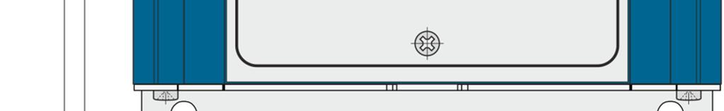


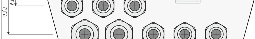
21 8.3 Dimensions FC 3500 DC Page 21 of 23
22 Appendix-A: FC 3500 BP display panel A1 Frontview FC 3500 BP drawing number w0 A2 Dimensions FC 3500 BP Attention: There may be more types of FC 3500 BP display units which may have different dimensions and front materials Page 22 of 23

23 A3 Connections FC 3500 BP Page 23 of 23
TRANSISTORIZED INVERTER -INSTRUCTION MANUAL- RELAY OUTPUT FR-A5AR
 TRANSISTORIZED INVERTER -INSTRUCTION MANUAL- RELAY OUTPUT FR-A5AR Thank you for choosing the Mitsubishi transistorized inverter option unit. This instruction manual gives handling information and precautions
FR-PU07 QUICK START MANUAL
 VARIABLE FREQUENCY DRIVE MODEL FR-PU07 QUICK START MANUAL 1. INTRODUCTION...3 1.1 SAFETY...3 2. APPEARANCE AND PARTS IDENTIFICATION...4 3. PARAMETERS TO BE CHECKED FIRST...4 4. FUNCTIONS...4 5. OVERVIEW
Mitsubishi Electric Automation Instruction Manual FR-A5AC-01
 Mitsubishi Electric Automation Instruction Manual FR-A5AC-01 AC Input Interface Option Unit NOTE: CAUTION: WARNING: NOTES, CAUTIONS AND WARNINGS Notes are used to provide additional detail about a procedure.
HITACHI. EH-150 series PLC EH-RTD8 Resistance Temperature Detective input module Instruction manual. Safety precautions
 HITACHI EH-150 series PLC Resistance Temperature Detective input module Instruction manual Thank you for purchasing a Hitachi Programmable Logic Controller. To operate it safely, please read this instruction
RТTH DUAL ROOM SWITCH
 DUAL ROOM SWITCH FOR TEMPERATURE AND RELATIVE HUMIDITY Mounting and operating instructions Table of contents SAFETY AND PRECAUTIONS PRODUCT DESCRIPTION ARTICLE CODES INTENDED AREA OF USE TECHNICAL DATA
Tempco Instruction Manual
 Tempco Instruction Manual 1/16 DIN Solid State Temperature Controller Relay Output Solid State Output For Heating Model Numbers: TEC-901, TEC-902, TEC-905 Temperature controls in this series are designed
RTT2 ROOM TEMPERATURE SWITCH. Mounting and operating instructions
 Mounting and operating instructions Table of contents SAFETY AND PRECAUTIONS PRODUCT DESCRIPTION ARTICLE CODES INTENDED AREA OF USE TECHNICAL DATA STANDARDS OPERATIONAL DIAGRAMS WIRING AND CONNECTIONS
VECTOR INVERTER -INSTRUCTION MANUAL- HIGH RESOLUTION ANALOG INPUT / EXTRA CONTACT INPUT / THERMISTOR INTERFACE FR-V5AX
 VECTOR INVERTER -INSTRUCTION MANUAL- HIGH RESOLUTION ANALOG INPUT / EXTRA CONTACT INPUT / THERMISTOR INTERFACE FR-V5AX Thank you for choosing the Mitsubishi vector inverter option unit. This instruction
FR-A8AR INSTRUCTION MANUAL
 INVERTER Plug-in option FR-A8AR INSTRUCTION MANUAL Relay output function PRE-OPERATION INSTRUCTIONS INSTALLATION AND WIRING RELAY OUTPUT 1 2 3 Thank you for choosing this Mitsubishi inverter plug-in option.
Emerson Network Power provides customers with technical support. Users may contact the nearest Emerson local sales office or service center.
 Liebert PSA iton User Manual Version: V2.8 Revision date: November 14, 2005 Emerson Network Power provides customers with technical support. Users may contact the nearest Emerson local sales office or
Non-communicating room controllers
 3 882 DESIGO RXA Non-communicating room controllers RXA29.1 For fan-coil systems The RXA29.1 room controller are used for temperature control in individual rooms. For 2-pipe or 4-pipe fan-coil systems,
INVERTER INSTRUCTION MANUAL. Relay output function. Plug-in option FR-A7AR PRE-OPERATION INSTRUCTIONS INSTALLATION AND WIRING RELAY OUTPUT
 INVERTER Plug-in option FR-A7AR INSTRUCTION MANUAL Relay output function PRE-OPERATION INSTRUCTIONS INSTALLATION AND WIRING RELAY OUTPUT 1 2 3 Thank you for choosing this Mitsubishi Inverter plug-in option.
USER MANUAL INSTALLATION MANUAL. Isolation transformers. ITR Isolation Transformer 7000 W 230V/32A
 USER MANUAL INSTALLATION MANUAL Isolation transformers ITR000702000 Isolation Transformer 7000 W 230V/32A Victron Energy B.V. The Netherlands General phone: +31 (0)36 535 97 00 Customer support desk: +31
Differential Liquid/Gas Pressure Transmitter
 Installation Instruction Differential Liquid/Gas Pressure Transmitter Catalog Number(s) 1414-CPZ10FWFAA, 1414-IPZ10FWFAA Explosion Hazard WARNING Do not use in an explosive or hazardous environment, with
QUICK START GUIDE. vau4/3. Frequency converter. operating instructions /12
 operating instructions QUICK START GUIDE Frequency converter vau4/3 28100241101 12/12 1 Safety information Warning of electrical shock! Danger to life! Electrical shock can cause serious injury or even
RXB10.1. Room controller. Siemens Building Technologies Building Automation DESIGO RXB. for chilled ceilings and radiators with EIB bus communication
 3 870 DESIO RXB Room controller for chilled ceilings and radiators with EIB bus communication RXB10.1 The RXB10.1 controller is used for temperature control in individual rooms: For chilled ceilings and
RXTP ROOM TEMPERATURE
 ROOM TEMPERATURE CONTROLLER WITH PI CONTROL Mounting and operating instructions Table of contents SAFETY AND PRECAUTIONS 3 PRODUCT DESCRIPTION 4 ARTICLE CODES 4 INTENDED AREA OF USE 4 TECHNICAL DATA 4
ATS-16 HV USER MANUAL. Automatic Transfer Switch 16A / 230Vac V090318
 ATS-16 HV Automatic Transfer Switch 16A / 230Vac USER MANUAL V090318 SAFETY Intended use The ATS-16 HV device serves as a power source selector to provide improved power supply for connected loads. ATS-16
IO-DI8-TO8 I/O Expansion Module 8 Inputs, 8 Outputs
 IO-DI8-TO8 I/O Expansion Module 8 Inputs, 8 Outputs The IO-DI8-TO8 is an I/O expansion module that can be used in conjunction with specific Unitronics OPLC controllers. The module offers 8 digital inputs,
INSTALLATION INSTRUCTIONS
 INSTALLATION INSTRUCTIONS Adaptor Model No. CZ-CFUNC1U For your safety Read the following instructions carefully, and carry out secure installation and electrical work. The precautions given in this manual
4-step Chiller and Heat Pump Controller
 4-step Chiller and Heat Pump Controller Technical Data Sheet GENERAL DESCRIPTION MODELS CODE MODEL DESCRIPTION MW324000 ECH 420 HEAT PUMP WITH 4 STEPS/ 2 CIRCUITS + MODBUS MW324005 ECH 420/V WITH SCREW
H Series PLC. ! : Indicates Compulsion. EH-150 Analog input module EH-AXH8M Instruction manual. Safety precautions DANGER CAUTION COMPULSION
 H Series PLC EH-150 Analog input module EH-AXH8M Instruction manual Thank you for purchasing a Hitachi Programmable Logic Controller. To operate it safely, please read this instruction manual and all the
EX-RC1 Remote I/O Adapter
 EX-RC1 Remote I/O Adapter The EX-RC1 interfaces between Unitronics Vision OPLCs and remote I/O Expansion Modules distributed throughout your system. The adapter is connected to a PLC via CANbus. Each adapter
STR-3 STANDARD 3-PHASE 230 VAC TRANSFORMER CONTROLLER. Mounting and operating instructions
 STANDARD 3-PHASE 230 VAC TRANSFORMER CONTROLLER Mounting and operating instructions Table of contents SAFETY AND PRECAUTIONS 3 PRODUCT DESCRIPTION 4 ARTICLE CODES 4 INTENDED AREA OF USE 4 TECHNICAL DATA
NIR Moisture Analyzer KB-30
 NIR Moisture Analyzer KB-30 Operation Manual Safety Precautions FPL950701 Improper use of the NIR moisture analyzer in violation of the following safety notes may result in death, injury or damage to property
PIEZO FEEDER CONTROLLER
 PIEZO FEEDER CONTROLLER Instruction Manual Single-Function Type P212 P312 This Instruction Manual is applicable to Piezo Feeder Controller version 1 and later. Confirm the version information displayed
EX-RC1 Remote I/O Adapter
 EX-RC1 Remote I/O Adapter The EX-RC1 interfaces between Unitronics Vision OPLCs and remote I/O Expansion Modules distributed throughout your system. The adapter is connected to a PLC via CANbus. Each adapter
Line Interactive 1000VA/1400VA/2000VA Uninterruptible Power System
 USER MANUAL Line Interactive 1000VA/1400VA/2000VA Uninterruptible Power System 614-06762-00 IMPORTANT SAFETY INSTRUCTIONS SAVE THESE INSTRUCTIONS This manual contains important instructions for Line Interactive
ATS22D62Q soft starter-ats22-control 220V-power 230V(15kW)/ V(30kW)
/ V(30kW)") Characteristics soft starter-ats22-control 220V-power 230V(15kW)/400...440V(30kW) Main Range of product Altistart 22 Product or component type Product destination Product specific application Component
Characteristics soft starter-ats22-control 220V-power 230V(15kW)/400...440V(30kW) Main Range of product Altistart 22 Product or component type Product destination Product specific application Component
VS-P Series. TDK-Lambda INSTRUCTION MANUAL
 VS5P /75P /1P/ 15P Instruction Manual BEFORE USING THE POWER SUPPLY UNIT Pay attention to all warnings and cautions before using the unit. Incorrect usage could lead to an electrical shock, damage to the
HPS-M -2 DIFFERENTIAL PRESSURE TRANSMITTER. Mounting and operating instructions
 DIFFERENTIAL PRESSURE Mounting and operating instructions Table of contents SAFETY AND PRECAUTIONS 3 PRODUCT DESCRIPTION 4 ARTICLE CODES 4 INTENDED AREA OF USE 4 TECHNICAL DATA 4 STANDARDS 5 OPERATIONAL
QXA2000 QXA2001. Condensation Monitor QXA2001 QXA2000 AQX2000
 1 542 1542P03 1542P01 1542P02 QXA2001 QXA2000 AQX2000 Condensation Monitor QXA2000 QXA2001 The QXA2000 condensation monitor is used to avoid damage due to condensation on chilled ceilings and in HVAC plant.
List of contents. 7-2 CE (ENC EN55022) declaration of conformity CE (LVD EN60950) declaration of conformity. 15 發行章
 declaration of conformity CE (LVD EN60950) declaration of conformity. 15 發行章") S150,S300 Series Pure Sine Wave Inverter User s Manual List of contents 1. IMPORTANT safety Information... 1 1-1 General Safety Precautions.. 1 1-2 Battery Precautions 1 2. Features. 2 2-1 Electrical Performance
S150,S300 Series Pure Sine Wave Inverter User s Manual List of contents 1. IMPORTANT safety Information... 1 1-1 General Safety Precautions.. 1 1-2 Battery Precautions 1 2. Features. 2 2-1 Electrical Performance
RXTH DUAL ROOM SENSOR / SWITCH
 DUAL ROOM SENSOR / SWITCH FOR TEMPERATURE AND RELATIVE HUMIDITY Mounting and operating instructions Table of contents SAFETY AND PRECAUTIONS 3 PRODUCT DESCRIPTION 4 ARTICLE CODES 4 INTENDED AREA OF USE
Operation Manual Series W-500
 Operation Manual Series W-500 Table of Content 1 Safety information... 2 1.1 Place of application of the unit... 2 1.2 Instructions for installation... 3 2 Start-up and adjustment of controller 4 3 General
Installation, Operation and Maintenance Manual
 Document 481200 VGD-100 Vari-Green Drive Installation, Operation and Maintenance Manual Please read and save these instructions for future reference. Read carefully before attempting to assemble, install,
USER MANUAL. Uninterruptible Power Supply Line-interactive VCL Series UPS VA. GE Critical Power
 Critical Power USER MANUAL Uninterruptible Power Supply Line-interactive VCL Series UPS 400 600 800 1000 1500 VA GE Consumer & Industrial SA General Electric Company CH 6595 Riazzino (Locarno) Switzerland
RST ROOM TEMPERATURE TRANSMITTER. Mounting and operating instructions
 Mounting and operating instructions Table of contents SAFETY AND PRECAUTIONS 3 PRODUCT DESCRIPTION 4 ARTICLE CODES 4 INTENDED AREA OF USE 4 TECHNICAL DATA 4 STANDARDS 4 OPERATIONAL DIAGRAM 5 WIRING AND
IO-DI8-RO8, IO-DI8-RO8-L I/O Expansion Modules 8 Inputs, 8 Outputs
 IO-DI8-RO8, IO-DI8-RO8-L I/O Expansion Modules 8 Inputs, 8 Outputs The IO-DI8-RO8 and IO-DI8-RO8-L are I/O expansion modules that can be used in conjunction with specific Unitronics OPLC controllers. The
IO-DI8-TO8, IO-DI8-TO8-L I/O Expansion Modules 8 Inputs, 8 Outputs
 IO-DI8-TO8, IO-DI8-TO8-L I/O Expansion Modules 8 Inputs, 8 Outputs The IO-DI8-TO8 and IO-DI8-TO8-L are I/O expansion modules that can be used in conjunction with specific Unitronics OPLC controllers. The
TOP - 1. Instruction Manual. Version 1.0 Produced in Jan. 2004
 Version 1.0 Produced in Jan. 2004 Instruction Manual LCD monitor IV-08MP Thank you for purchasing the SHARP IV-08MP LCD monitor. Read this introductory instruction manual carefully to thoroughly familiarize
DXTH DUCT SENSOR / SWITCH FOR TEMPERATURE AND HUMIDITY. Mounting and operating instructions
 DUAL DUCT SENSOR / SWITCH FOR TEMPERATURE AND HUMIDITY Mounting and operating instructions Table of contents SAFETY AND PRECAUTIONS 3 PRODUCT DESCRIPTION 4 ARTICLE CODES 4 INTENDED AREA OF USE 4 TECHNICAL
PLC-24V10AL(-PT/-TH) Quick Start Manual (Rev.1.10)
 Quick Start Manual (Rev.1.10)") TEC (Peltier) Controller PLC-24V10AL(-PT/-TH) Quick Start Manual (Rev.1.10) Thank you for purchasing the TEC (Peltier) Controller PLC-24V10AL. Read these operating instructions carefully to ensure effective
TEC (Peltier) Controller PLC-24V10AL(-PT/-TH) Quick Start Manual (Rev.1.10) Thank you for purchasing the TEC (Peltier) Controller PLC-24V10AL. Read these operating instructions carefully to ensure effective
SINUS PENTA 6. ACCESSORIES 6.1. BRAKING RESISTORS APPLICATION TABLES 111/209
 INSTALLATION. ACCESSORIES.. BRAKING RESISTORS... APPLICATION TABLES From size S to size S, inverters are supplied with a built-in braking module. The braking resistor is to be connected outside the inverter
User safety and equipment protection guidelines
 Snap-in I/O Module The V200-18-E1 plugs directly into the back of compatible Unitronics OPLCs, creating a selfcontained PLC unit with a local I/O configuration. The module offers: 3 analog inputs 16 digital
CRM Control Panel and Weather Detection System CRM3 for DC actuators (part # 40821J) CRM4 for AC actuators (part # 40822K)
 CRM4 for AC actuators (part # 40822K)") CRM Control Panel and Weather Detection System CRM3 for DC actuators (part # 40821J) CRM4 for AC actuators (part # 40822K) CRM Applications CRM includes a control relay box and a power supply; additional
CRM Control Panel and Weather Detection System CRM3 for DC actuators (part # 40821J) CRM4 for AC actuators (part # 40822K) CRM Applications CRM includes a control relay box and a power supply; additional
External level devices for conductive point level switch
 SENSORS FOR FOOD AND BIOPHARMA. Product Information VNV-2, ZNV-2 CONTROLS External level devices for conductive point level switch Application/Specified usage Point level detection of aqueous, conductive
IO-PT4. Component identification. User safety and equipment protection guidelines. Unitronics Industrial Automation Systems 1
 IO-PT4 I/O Expansion Module 4 PT100 Inputs (-50 to 460 C) The IO-PT4 is an I/O expansion module that can be used in conjunction with specific Unitronics OPLC controllers. The module offers 4 PT100 inputs
EX-RC1 Remote I/O Adapter
 EX-RC1 Remote I/O Adapter The EX-RC1 interfaces between Unitronics Vision OPLCs and remote I/O Expansion Modules distributed throughout your system. The adapter is connected to a PLC via CANbus. Each adapter
MVS RAIL ELECTRONIC FAN SPEED CONTROLLER. Mounting and operating instructions
 DIN RAIL ELECTRONIC FAN SPEED Mounting and operating instructions Table of contents SAFETY AND PRECAUTIONS 3 PRODUCT DESCRIPTION 4 ARTICLE CODES 4 INTENDED AREA OF USE 4 TECHNICAL DATA 4 STANDARDS 5 WIRING
Accessories for stand-alone gird inverter SMART LOAD 6000
 Accessories for stand-alone gird inverter SMART LOAD 6000 Technical Description SL6000-TEN081820 98-2001320 Version 2.0 EN Table of Contents Table of Contents 1 Notes on this Manual..............................
MDM 011-Z1 Regen Resistor
 MDM 011-Z1 Regen Resistor Date of creation: 10.04.2017 Version date: 10.04.2017 Article number: 09-402-011-Z1-E Publisher: SIGMATEK GmbH & Co KG A-5112 Lamprechtshausen Tel.: 06274/4321 Fax: 06274/4321-18
OPERATING INSTRUCTIONS PA AMPLIFIER P-1812
 OPERATING INSTRUCTIONS PA AMPLIFIER P-1812 Please follow the instructions in this manual to obtain the optimum results from this unit. We also recommend that you keep this manual handy for future reference.
LXEM145 SERIES Lanx Australis single Phase KWh Meter 45Amp. User manual
 LXEM145 SERIES Lanx Australis single Phase KWh Meter 45Amp Single phase two wire DIN rail energy meter (One module) 1.1 Safety instruction 1.2 Foreword 1.3 Performance criteria 1.4 Specifications 1.5 Basic
SA-150, SA-300 Series Pure Sine Wave Inverter User s Manual
 SA-150, SA-300 Series Pure Sine Wave Inverter User s Manual List of contents 1. IMPORTANT safety Information... 1 1-1 General Safety Precautions.. 1 1-2 Battery Precautions 1 2. Features. 2 2-1 Electrical
Conductive Level Controller
 Conductive Level Controller 61F-D21T-V1 Ideal for level control for industrial facilities and equipment. Outputs can be set to self-hold at ON or OFF using self-holding circuits. Sensitivity adjustment
E2Q4 Square Proximity Sensor
 Inductive Square Slim, compact size M2 Plug-in connection Integrated short circuit and reverse polarity protection Active face positioning: Y-axis 5, X-axis 90 incremets Ordering Information DC type Connection
JANOME DESKTOP ROBOT JR2000N Series. Operation Manual. <Setup> For Qualified Installer ONLY
 JANOME DESKTOP ROBOT JR2000N Series Operation Manual For Qualified Installer ONLY Thank you for purchasing the Janome Robot. *Read this manual thoroughly in order to properly use this robot. Be sure
ATS22D75S6 soft starter-ats22-control 220V-power 230V(18.5kW)/ V(37kW)/500V(45kW)
/ V(37kW)/500V(45kW)") Characteristics soft starter-ats22-control 220V-power 230V(18.5kW)/400...440V(37kW)/500V(45kW) Price* : 683.00 GBP Main Range of product Altistart 22 Product or component type Product destination Product
Characteristics soft starter-ats22-control 220V-power 230V(18.5kW)/400...440V(37kW)/500V(45kW) Price* : 683.00 GBP Main Range of product Altistart 22 Product or component type Product destination Product
ADC7520 SERIES. 1600W Battery Chargers and Power Supplies
 ADC7520 SERIES 1600W Battery Chargers and Power Supplies Wide output adjustment range 0 72VDC Analog control by external 0-5VDC voltage Temp.comp charging, sense as on option Power fail relay alarm Master-Slave
ATS22D17Q soft starter-ats22-control 220V-power 230V(4kW)/ V(7.5kW)
/ V(7.5kW)") Characteristics soft starter-ats22-control 220V-power 230V(4kW)/400...440V(7.5kW) Main Range of product Altistart 22 Product or component type Product destination Product specific application Component
Characteristics soft starter-ats22-control 220V-power 230V(4kW)/400...440V(7.5kW) Main Range of product Altistart 22 Product or component type Product destination Product specific application Component
Component identification
 IO-ATC8 I/O Expansion Module 8 Analog/Thermocouple Inputs The IO-ATC8 is an I/O Expansion Module that can be used in conjunction with specific Unitronics OPLC controllers. The module offers 8 inputs that
Switched Mode Power Supply Operating manual PAP800
 Features: Switched mode power supply Wide output 0 144Vdc Analog control by an external 0 5Vdc Power failure alarm output Master-slave connection Powerfinn PAP series is a high power, lightweight, advanced
PAR-WT50R-E PAR-WR51R-E
 Wireless Remote Controller and Receiver PAR-WT50R-E PAR-WR51R-E This manual explains installation of the PAR-WR51R-E wireless receiver and the PAR-WT50R-E wireless remote controller, and settings of these
Power Supply. Users Guide PRODUCT MANUAL. WESTELL.COM Westell Technologies MNL rd
 PRODUCT MANUAL Power Supply Westell Technologies. 960-1152-MNL rd DISCLAIMER All information and statements contained herein are accurate to the best of Westell Technologies knowledge. Westell Technologies
CONTROL ANYTHING WITH YOUR CELLPHONE. Use your cellphone to remotely monitor and control the following applications with the CELLSWITCH 100
 CELLSWITCH 100 CONTROL ANYTHING WITH YOUR CELLPHONE Use your cellphone to remotely monitor and control the following applications with the CELLSWITCH 100 Security: Electric Fence / Power-failure / Fire
User Manual. Solar Inverter for Water Pump
 User Manual Solar Inverter for Water Pump SP Revival Series Version: 1.2 Table Of Contents ABOUT THIS MANUAL... 1 Purpose... 1 Scope... 1 SAFETY INSTRUCTIONS... 1 Inspection... 1 Installation... 1 Operation...
ELV12 Series. Instruction Manual
 Instruction Manual TDK-Lambda BEFORE USING POWER SUPPLY UNIT Be sure to read this instruction manual thoroughly before using this product. Pay attention to all warnings and cautions before using the unit.
SDM120 SERIES. SDM120 series User Manual. Single phase two wire DIN rail energy meter (One module)
") SDM120 SERIES Single phase two wire DIN rail energy meter (One module) User manual ------------ 1.1 Safety instruction 1.2 Foreword 1.3 Performance criteria 1.4 Specifications 1.5 Basic errors 1.6 Dimension
SDM120 SERIES Single phase two wire DIN rail energy meter (One module) User manual ------------ 1.1 Safety instruction 1.2 Foreword 1.3 Performance criteria 1.4 Specifications 1.5 Basic errors 1.6 Dimension
TPE 1464 Series Pressure Transducer
 TPE 1464 Series Pressure Transducer Description The KMC TPE 1464 series of pressure transducers incorporate a gauge pressure transmitter featuring low hysteresis, excellent repeatability, and longterm
Operating Instructions Differential Pressure Transducer PS27
 Operating Instructions Differential Pressure Transducer PS27 halstrup-walcher GmbH Stegener Straße 10 79199 Kirchzarten/Germany Phone: +49 (0) 76 61/39 63 0 Fax: +49 (0) 76 61/39 63 99 E-mail: info@halstrup-walcher.com
INSTRUCTION MANUAL TRIP CIRCUIT SUPERVISION RELAY GKAD1
 INSTRUCTION MANUAL TRIP CIRCUIT SUPERVISION RELAY GKAD1 TOSHIBA Corporation 2004 All Rights Reserved. ( Ver. 1.6 ) Safety Precautions Before using this product, please read this chapter carefully. This
Model HM-535 Power Supply Installation and Service Instructions
 Model HM-535 Power Supply Installation and Service Instructions 430-535 0104 2004 Heritage MedCall, Inc SENTRY INSTALLATION & SERVICE INSTRUCTIONS POWER SUPPLY UNIT Model HM-535 IMPORTANT SAFETY INSTRUCTIONS
SINAMICS G130. Terminal Module 150 (TM150) Operating Instructions 03/2013 SINAMICS
 Operating Instructions 03/2013 SINAMICS") SINAMICS G130 Operating Instructions 03/2013 SINAMICS s Safety information 1 General information 2 SINAMICS SINAMICS G130 Mechanical installation 3 Electrical installation 4 Technical specifications 5
SINAMICS G130 Operating Instructions 03/2013 SINAMICS s Safety information 1 General information 2 SINAMICS SINAMICS G130 Mechanical installation 3 Electrical installation 4 Technical specifications 5
Thermoelectric Cooler Controller TED1000
 Thermoelectric Cooler Controller TED1000 Operating Instructions MANUAL-TED1000-1.0 Aug 2015 Rev.1 2 Contents 1 General... 4 1.1 Warranty and Assistance... 4 1.2 Maintenance... 4 1.3 General Safety Considerations...
IO-AO6X I/O Expansion Module 6 Isolated Analog Outputs
 IO-AO6X I/O Expansion Module 6 Isolated Analog Outputs The IO-AO6X is an I/O Expansion Module that can be used in conjunction with specific Unitronics OPLC controllers. The module offers 6 12-bit isolated
Temperature controller Ducted systems
 2 725 Temperature controller Ducted systems Standard model without zoning functions RRV851 Multifunctional controller used for central control of ducted HVAC systems in combination with a QAX850 master
TEMPERATURE CONTROLLER 2 HEAT/ 2 COOL with Digital Room Temperature Display. Made in Australia 100% Australian Owned Company
 TEMPERATURE CONTROLLER 2 HEAT/ 2 COOL with Digital Room Temperature Display HTC 5 Features Australian Made and designed Power can be either 24V or 240V AC 10 Amp (Resistive) Potential free relay contacts
2.) Cabinet setup and preset data shall, as standard, be fully user programmable on a per cabinet or system wide basis.
 Cabinet setup and preset data shall, as standard, be fully user programmable on a per cabinet or system wide basis.") A21 DIMMER CABINET SPECIFICATION. GENERAL. A.) Overview. 1.) The dimmer cabinets shall be fully digital, designed specifically for architectural and entertainment lighting applications, and shall consist
A21 DIMMER CABINET SPECIFICATION. GENERAL. A.) Overview. 1.) The dimmer cabinets shall be fully digital, designed specifically for architectural and entertainment lighting applications, and shall consist
7032 Digital-Analog Multimeter
 7032 Digital-Analog Multimeter OPERATOR S MANUAL CONTENTS: 1. Safety precautions and procedures 1 1.1. Preliminary 1 1.2. During Use 2 1.3. After Use.. 2 2. General Description. 3 3. Preparation for Use..
PHASETRONICS. SCR Power Control Specialists. EP1 Series Power Control Single Phase SCR Amps OPERATION & SERVICE MANUAL
 PHASETRONICS Specialists EP1 Series Power Control Single Phase SCR 10-50 Amps OPERATION & SERVICE MANUAL Phasetronics, Inc. P.O. Box 5988 1600 Sunshine Drive Clearwater, FL 33765 (727)573-1900 FAX(727)573-1803
Blitzer Strobe. User Manual. Order code: EQLED366
 Blitzer Strobe User Manual Order code: EQLED366 Safety advice WARNING FOR YOUR OWN SAFETY, PLEASE READ THIS USER MANUAL CAREFULLY BEFORE YOUR INITIAL START-UP! Before your initial start-up, please make
RXB39.1. Room controller RXB. Communicating room controller for fan-coil applications FC-13
 s 3 875 RXB Room controller Communicating room controller for fan-coil applications FC-13 RXB39.1 The RXB39.1 room controller is used for temperature control in individual rooms. For 2-pipe or 4-pipe fan-coil
F1000 User's Manual. (Version: V1.01)
") (Version: V1.01) Contents Chapter 1 Overview... 2 Chapter 2 Installation... 3 2.1 Installation guide... 3 2.1.1 Installation position... 3 2.1.2 NEMA4 standard installation... 3 2.1.3 Environment precautions...
(Version: V1.01) Contents Chapter 1 Overview... 2 Chapter 2 Installation... 3 2.1 Installation guide... 3 2.1.1 Installation position... 3 2.1.2 NEMA4 standard installation... 3 2.1.3 Environment precautions...
Non-communicating room controllers
 3 881 DESIO RXA on-communicating room controllers For fan-coil systems RXA20.1 RXA21.1 RXA22.1 The RXA20.1, RXA21.1 and RXA22.1 room controllers are used for temperature control in individual rooms. For
User Manual. 2.2KW LS (Low PV Input Range) Solar Inverter for Water Pump. Version: 1.1
 Solar Inverter for Water Pump. Version: 1.1") User Manual 2.2KW LS (Low PV Input Range) Solar Inverter for Water Pump Version: 1.1 Table Of Contents ABOUT THIS MANUAL... 1 Purpose... 1 Scope... 1 SAFETY INSTRUCTIONS... 1 Inspection... 1 Installation...
User Manual 2.2KW LS (Low PV Input Range) Solar Inverter for Water Pump Version: 1.1 Table Of Contents ABOUT THIS MANUAL... 1 Purpose... 1 Scope... 1 SAFETY INSTRUCTIONS... 1 Inspection... 1 Installation...
OPERATOR S MANUAL 9000U ISOLATOR
 OPERATOR S MANUAL 9000U ISOLATOR Masibus Automation And Instrumentation Pvt. Ltd. B/30, GIDC Electronics Estate, Sector-25, Gandhinagar-382044, Gujarat, India Ph: 91 79 23287275-79 Fax: 91 79 23287281,
ATS22D88S6U. ATS22D88S6U soft starter-ats22-control110v-power 208V(25hp)/230V(30hp)/460V(60hp)/575V(75hp) Product data sheet Characteristics.
/230V(30hp)/460V(60hp)/575V(75hp) Product data sheet Characteristics.") Characteristics soft starter-ats22-control110v-power 208V(25hp)/230V(30hp)/460V(60hp)/575V(75hp) Main Range of product Altistart 22 Product or component type Product destination Product specific application
Characteristics soft starter-ats22-control110v-power 208V(25hp)/230V(30hp)/460V(60hp)/575V(75hp) Main Range of product Altistart 22 Product or component type Product destination Product specific application
Room Temperature Controller
 3 023 Room Temperature Controller for four-pipe fan coil units RCC30 Outputs for on / off valve actuators Outputs for three-speed fan Control depending on room or return air temperature Operating modes:
ATS22D75Q soft starter-ats22-control 220V-power 230V(18.5kW)/ V(37kW)
/ V(37kW)") Product data sheet Characteristics ATS22D75Q soft starter-ats22-control 220V-power 230V(18.5kW)/400...440V(37kW) Complementary Assembly style Function available Power supply voltage limits Main Range of
Product data sheet Characteristics ATS22D75Q soft starter-ats22-control 220V-power 230V(18.5kW)/400...440V(37kW) Complementary Assembly style Function available Power supply voltage limits Main Range of
7x15W 4IN1 Infinity Rotation LED Pixel Bar. This product manual contains important information about the safe
 Pixel Beam K7 7x15W 4IN1 Infinity Rotation LED Pixel Bar This product manual contains important information about the safe installation and use of this projector. Please read and follow these instructions
SAFETY RELAY YRB-4EML-31S MAIN FEATURES
 SAFETY RELAY TYPE 4 SAFETY PROTECTION DEVICE FOR SAFETY LIGHT CURTAINS/BARRIERS MAIN FEATURES For safety light curtains and access control barriers, emergency stop, door switch Safety Integrity Level (SIL)
3-150 KVA THREE-PHASE SERVO REGULATOR INSTRUCTIONS FOR USE SERVO THREE-PHASE VOLTAGE REGULATOR
 3-150 KVA THREE-PHASE SERVO REGULATOR INSTRUCTIONS FOR USE SERVO THREE-PHASE VOLTAGE REGULATOR I Important Notice! Thank you for preferring us. Your product has been designed to protect your sensitive
The power behind competitiveness. Delta Infrasuite Power Management. Power Distribution Unit. User Manual.
 The power behind competitiveness Delta Infrasuite Power Management Power Distribution Unit User Manual www.deltapowersolutions.com Save This Manual This manual contains important instructions and warnings
Operating instructions
 SOLARTHERMIE - SOLAR THERMAL - SOLAR TÉRMICO - SOLAIRE THERMIQUE Operating instructions Temperature Difference Controller 6 inputs / outputs EN 714.884 08.15 ZO 714.884 08.15 1 Case overview Operating
Overview. Applications. Benefits. Ordering Information. Sensors OHD Thermal Guard
 Sensors OHD Thermal Guard Overview The OHD Thermal Guard is developed for thermal problem countermeasures and safety standard conformity, which are becoming increasingly important for electronic devices
Series Pressure Sensor Instruction Sheet
 2018/05/10 Series ure Sensor Instruction Sheet Thank you very much for choosing Delta DPA series pressure sensor. Please read this instruction sheet carefully before using your DPA. Keep this instruction
DESIGO RX Individual room controllers. for fan-coil systems, chilled ceilings and radiators, with LONMARK-compatible bus communications
 3 834 DESIO RX Individual room controllers for fan-coil systems, chilled ceilings and radiators, with MARK-compatible bus communications RXC20.1 RXC21.1 The RXC20.1 and RXC21.1 controllers are used for
User Manual. 2.2KW/7.5KW/11KW Solar Inverter for Water Pump. Version: 1.8
 User Manual 2.2KW/7.5KW/11KW Solar Inverter for Water Pump Version: 1.8 Table Of Contents ABOUT THIS MANUAL... 1 Purpose... 1 Scope... 1 SAFETY INSTRUCTIONS... 1 Inspection... 1 Installation... 1 Operation...
Operating Instructions. For. Level Control Module. Model SSR 1000
 Operating Instructions For Level Control Module Model SSR 1000 SSR Operation Instructions Rev. 1 Jan 01 Page 1/7 1. Note Please read and take note of these operating instructions before unpacking and commissioning.