Copyright: December 2017 Nidec Issue: E
|
|
|
- Malcolm Lucas
- 5 years ago
- Views:
Transcription
1
2 General Information The manufacturer accepts no liability for any consequences resulting from inappropriate, negligent or incorrect installation or adjustment of the optional parameters of the equipment or from mismatching the starter with the motor. The contents of this guide are believed to be correct at the time of printing. In the interests of commitment to a policy of continuous development and improvement, the manufacturer reserves the right to change the specification of the product or its performance, or the content of the guide without notice. All rights reserved. No parts of this guide may be reproduced or transmitted in any form or by any means, electrical or mechanical including, photocopying, recording or by an information storage or retrieval system, without permission in writing from the publisher. Copyright: December 2017 Nidec
3 Contents 1. Introduction Important User Information Installation Installation Procedure Physical installation Profibus Module Connection and Configuration Adjustment Connection LEDs Master Configuration Configuration Operating modules Data Structures Soft Starter Control I/O Data Structure Soft Starter Monitoring I/O Data Structure Soft Starter Programming I/O Data Structure Profibus Diagnostics and Modes Profibus Diagnostic Telegram and Flag Profibus Freeze Mode Profibus Sync Mode Profibus Clear Mode Specifications Profibus Module: User Guide 3
4 1. Introduction The Profibus Module can be used with Digistart D2 and Digistart D3 soft starters to allow the starter to be connected to a serial communications network using the Profibus protocol. 2. Important User Information Observe all necessary safety precautions when controlling the soft starter remotely. Alert personnel that machinery may start without warning. It is the installer's responsibility to follow all instructions in this manual and to follow correct electrical practice. 3. Installation CAUTION Remove mains and control voltage from the soft starter before attaching or removing accessories. Failure to do so may damage the equipment. 3.1 Installation Procedure 1. Remove control power and mains supply from the soft starter. 2. Attach the module to the soft starter as illustrated. 3. Set the module address to match the address set in the Master configuration tool. 4. Apply control power to the soft starter. 5. Insert the network connector and power up the module. 3.2 Physical installation 1. Fully pull out the top and bottom retaining clips on the module. 2. Line up the module with the comms port slot. 3. Push in the top and bottom retaining clips to secure the module to the starter. Figure 3-1 Attach the module to the starter A B C C 4 Profibus Module: User Guide
5 Figure 3-2 Remove the module from the starter Remove the module using the following procedure: 1. Take the module off-line. 2. Remove control power and mains supply from the soft starter. 3. Disconnect all external wiring from the module. 4. Fully pull out the top and bottom retaining clips on the module. 5. Pull the module away from the soft starter. A C Profibus Module: User Guide 5
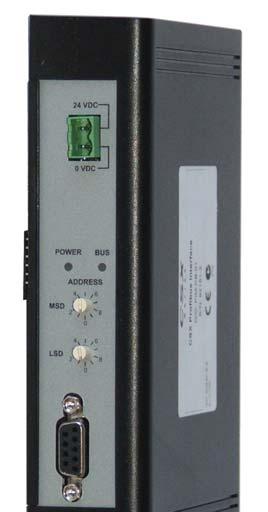
6 4. Profibus Module Connection and Configuration 4.1 Adjustment Figure 4-1 Adjustment switches Before powering up the Profibus Module, set the two rotary switches so that the module address matches the address set in your Master configuration tool. eg MSD = 2 and LSD = 1 corresponds to address 21. (The diagram shows the factory default setting for the rotary switches). The module automatically detects the network data rate. MSD ADDRESS LSD 4.2 Connection The module connects to the Profibus network via a standard DB9 connector. The Profibus Module can be powered either through the network cable or externally (24 Vdc). Figure 4-2 Profibus Module connections Digistart D2 1 Digistart D A A Digistart D2 CSL, DI2: Stop input Profibus Module External 24 Vdc supply required if not powered through bus DB9 connector to Profibus network Digistart D3 (Remote mode) DI2, +24V: Stop input DI3, +24V: Reset input Profibus Module External 24 Vdc supply required if not powered through bus DB9 connector to Profibus network Digistart D2: For the Profibus Module to accept serial commands, a link must be fitted across terminals CSL-DI2 on the soft starter. Digistart D3: Input links are required across the stop and reset inputs if the soft starter is being operated in Remote mode. In Local mode, links are not required. If the Starter Disable function is not required, change the setting of Pr 3A or connect a link across DI4, +24V. NOTE Digistart D3: Control via the serial communication network is always enabled in local control mode, and can be enabled or disabled in remote control mode (Pr 3O Comms in Remote). See the soft starter user manual for parameter details. 6 Profibus Module: User Guide
7 Pin No. 1 Shield 2 24 Vdc negative (optional) 3 RxD/TxD-P 4 Not used 5 DGND 6 VP (end of bus slave only) 7 24 Vdc positive (optional) 8 RxD/TxD/-N 9 DGND 4.3 LEDs Figure 4-3 Feedback LEDs DB9 connector Assignment 1 2 OFF ON Power status (red) Module not powered up Module powered up and ready to go online Bus status (green) No connection, offline or data exchange failure Module online and in data exchange state C NOTE If communication fails between the module and the network, the Bus Status LED will go off. When communication is restored, the Bus Status LED will come back on. NOTE When a communications failure occurs, the soft starter may trip if the Communication Timeout parameter for the network is set greater than zero. When communication is restored, the soft starter must be reset. 5. Master Configuration 5.1 Configuration Import the latest.gsd file into your Master configuration tool. This file is available from. If your Master uses on-screen icons, two graphic bitmap files are available from the website. SSPM_N.bmp indicates normal mode. SSPM_D.bmp indicates diagnostic mode. NOTE The Profibus Module has a slave address range of 0 to 99. If the Profibus network fails, the module will leave data exchange mode after the network watchdog timeout period has expired. This timeout period is set at the Master configuration tool. A Communication Timeout parameter in the GSD file sets how soon after this event the soft starter will be forced into a trip state. The user can adjust the Communication Timeout parameter in the GSD file to any setting between 0 and 100 seconds. The default setting is 10 seconds. NOTE If the Communication Timeout parameter is set to 0, the current state of the soft starter will remain unchanged on a network failure. This gives the user the option of operating the soft starter via local control, but is NOT failsafe. 5.2 Operating modules The GSD file contains three operating modules, supporting data I/O structures as follows: Table 5-1 Data structures Data Structure Basic Module Extended Module Parameter Upload/ Download Module Soft Starter Control I/O Data Structure on page 8 Soft Starter Monitoring I/O Data Structure on page 9 Soft Starter Programming I/O Data Structure on page 12 The Basic Module allows the user to start and stop the soft starter and read limited information on operating status. The Extended Module defines additional bytes allowing the user to read soft starter operating data such as actual motor current and motor temperature. The Parameter Upload/Download Module allows the user to read and write soft starter parameter values (only applicable to Digistart D3 soft starters). Profibus Module: User Guide 7
8 6. Data Structures 6.1 Soft Starter Control I/O Data Structure Master > Slave control word is structured as follows: Table 6-1 Control I/O data structure Byte 0 Bit 7 Bit 6 Bit 5 Bit 4 Bit 3 Bit 2 Bit 1 Bit 0 Reserved Reserved Reserved Quick stop Motor set Reserved Reserved Byte 1 Bit 7 Bit 6 Bit 5 Bit 4 Bit 3 Bit 2 Bit 1 Bit 0 Reserved Reserved Reserved Reserved Reset Reserved Reserved Fwd run Quick Stop Bit When Fwd run bit changes from 1 to 0: 0 = stop action will be a soft stop (as selected on the soft starter). 1 = stop action will be a quick stop (ie coast to stop). NOTE The Quick stop bit must be set to 0 before the soft starter can perform a start. Motor Set Bits (Digistart D3 only) Selects which parameter set to use when starting: 0 = selected from soft starter remote input (programmable input must be set to 'Motor Set Select') 1 = soft starter primary motor set (ensure soft starter programmable input is not set to 'Motor Set Select') 2 = soft starter secondary motor set (ensure soft starter programmable input is not set to 'Motor Set Select') 3 = Reserved NOTE If Pr 3A Input A Function for Digistart D3 is set to motor set select, this will cause a conflict with motor set selection via serial communications. Slave > Master status word is structured as follows: Table 6-2 Status word structure Byte 0 Bit 7 Bit 6 Bit 5 Bit 4 Bit 3 Bit 2 Bit 1 Bit 0 Ramping Local 2 Motor current (% FLC) 1 Byte 1 Bit 7 Bit 6 Bit 5 Bit 4 Bit 3 Bit 2 Bit 1 Bit 0 Reserved Reserved Reserved Reserved Warning 2 Fault On Ready 1 Motor current (% FLC) represents current as a percentage of the set motor full load current. A maximum value of 63 represents 200% full load current. To convert this value to a readable percentage, divide by For models D3-0053B and smaller this value will be 10 times greater than the value displayed on the keypad. 2 Only available on Digistart D3 soft starters. Ready is set when the soft starter is ready to start the motor. On is set when the soft starter is starting, running or soft stopping the motor. Warning is set when the soft starter detects a warning condition. Fault is set when the soft starter has tripped. Ramping is set when the soft starter is starting or soft stopping the motor. Local is set when the soft starter is set to Local mode. 8 Profibus Module: User Guide
9 6.2 Soft Starter Monitoring I/O Data Structure Master > Slave output byte is structured as follows: Table 6-3 Monitoring I/O data structure Operating data request (Data request numbers 1 to 16) Byte 2 Slave > Master input bytes, in response to an operating data request, are structured as follows: Byte 2 Echo data request number Byte 3 Bits 7 to 1 Reserved Bit 0 = 1: Invalid data request number Byte 4 Data value - high byte Byte 5 Data value - low byte NOTE An invalid data request number will result in the invalid data request number bit being set = 1. NOTE Data request numbers 4 (only Motor 2 Temperature ) to 16 are only valid for Digistart D3 starters. Digistart D2 starters will return zero values. Data values are defined as follows: Table 6-4 Data values Data Request Number Data Value High Byte Data Value Low Byte 0 Reserved 1 Soft starter product type code 1 Soft starter software version number 2 Trip/Warning code Soft starter status 3 2 Average current (high byte) Average current (low byte) 4 3 Motor 2 temperature Motor 1 temperature 5 Reserved % Power factor 6 Power (kw) 7 Power (kva) 8 Average voltage 9 2 L1 current 10 2 L2 current 11 2 L3 current 12 Reserved 13 Reserved 14 Reserved 15 Software major version number Software minor revision number 16 Reserved Digital Input state 1 Product type code: 4 = Digistart D2 8 = Digistart D3 2 For models D3-1x-0053-B and smaller this value will be 10 times greater than the value displayed on the keypad. 3 Motor temperature is calculated using the soft starter thermal modelling Power Input bytes for data request numbers 6 and 7 are defined as follows: Bit 7 Bit 6 Bit 5 Bit 4 Bit 3 Bit 2 Bit 1 Bit 0 High Byte Power scale factor Power high nibble Low Byte Power low byte Powerscale functions as follows: 0 = multiply Power by 10 to get W 1 = multiply Power by 100 to get W 2 = Power is represented in kw 3 = multiply Power by 10 to get kw Profibus Module: User Guide 9
10 6.2.2 Soft Starter Status The low byte data value of data request number 2 reports soft starter status. Bits 0 to 3 function as follows: Table 6-5 Status byte Value (decimal) Bits 0 to 3 Soft Starter Status 0 Unknown (communication error between module and soft starter) 1 Ready to start (waiting) 2 Starting (soft starting) 3 Running (running full voltage at the motor) 4 Stopping (soft stopping) 5 Not ready (restart delay, restart temperature check, run simulation, input A (DI4, +24V) not shorted) 6 Fault (tripped) 7 1 Menu or Logs Menu open (cannot start) 8 1 Jog Forward (slow speed) 9 1 Jog Reverse (slow speed) 1 Only available on Digistart D3 soft starters. Bits 4 to 7 function as follows: Bit Number Function Bit 4 Set if positive phase sequence detected (Bit 6 must = 1) Bit 5 Set if average current exceeds Motor FLC setting Bit 6 Set after first start once phase sequence has been confirmed Bit 7 Set if a communication failure occurs between module and soft starter Digital Input State The low byte of data request number 16 reports digital input state as follows (0 = open, 1 = closed): Bit 7 Bit 6 Bit 5 Bit 4 Bit 3 Bit 2 Bit 1 Bit 0 Low Byte Reserved Input D Input C Input B Input A Reset Stop Start 10 Profibus Module: User Guide
11 6.2.4 Trip Codes Table 6-6 Trip messages Trip Code Description Digistart D2 Digistart D3 1 Excess start time 2 Motor overload (thermal model) 3 Motor thermistor 4 Current imbalance 5 Frequency (Mains supply) 6 Phase sequence 7 Instantaneous overcurrent 8 Power loss / Power circuit 10 Heatsink overtemperature 11 Motor Connection Tx 12 Input trip 13 FLC too high (FLC out of range) 14 Unsupported option (function not available in inside delta) 15 Starter communication (between module and soft starter) 16 Network communication (between module and network) 17 Internal fault x (where x is the fault code detailed in the table below) 20 1 Ground fault 23 Parameter out of Range 24 Input B trip 26 L1 phase loss 27 L2 phase loss 28 L3 phase loss 29 L1-T1 shorted 30 L2-T2 shorted 31 L3-T3 shorted 32 Motor 2 overload (thermal model) 33 2 Time-overcurrent (Bypass overload) 35 Battery/clock 36 Thermistor circuit 37 RTD/PT100 A 38 1 RTD/PT100 B 39 1 RTD/PT100 C 40 1 RTD/PT100 D 41 1 RTD/PT100 E 42 1 RTD/PT100 F 43 1 RTD/PT100 G 45 RTD/PT100 X Circt 46 Analog input trip 47 Overpower 48 Underpower 255 No trip 1 Available with Digistart D3 only if the appropriate option card is fitted. 2 For Digistart D3, time-overcurrent protection is only available on internally bypassed models. Profibus Module: User Guide 11
12 6.2.5 Internal Fault x The table below details the internal fault code associated with trip code 17. Table 6-7 Internal fault X Internal fault 70 to 72 Current Read Err Lx 73 ATTENTION! Remove Mains Volts 74 to 76 Motor Connection Tx 77 to 79 Firing Fail Px 80 to 82 VZC Fail Px 83 Low Control Volts 84 to 98 Internal fault X Contact your local supplier with the fault code (X). Message displayed on the keypad 6.3 Soft Starter Programming I/O Data Structure The Soft Starter Programming I/O Data Structure allows the user to upload (read) and download (write) soft starter values over the network. Master > Slave output bytes are structured as follows. Table 6-8 Programming output byte structure Byte 3 Byte 4 Byte 5 Byte 6 Bit 7 Bit 6 Bit 5 Bit 4 Bit 3 Bit 2 Bit 1 Bit 0 Parameter number to read/write Write Read Reserved Reserved Reserved Reserved Reserved parameter parameter High byte parameter value to write to soft starter/ zero data values for read Low byte parameter value to write to soft starter/ zero data values for read Reserved Slave > Master input bytes are structured as follows. Table 6-9 Programming input byte structure Bit 7 Bit 6 Bit 5 Bit 4 Bit 3 Bit 2 Bit 1 Bit 0 Byte 6 Byte 7 Byte 8 Byte 9 Echo parameter number Reserved Reserved Reserved Parameter access level Parameter access level is defined as follows: 0 = Read only 1 = Operator (Digistart D3 parameter groups 1 to 14) 2 = Supervisor (Digistart D3 parameter groups 15 and 16) Write access denied High byte parameter value read from soft starter Low byte parameter value read from soft starter Invalid parameter value Invalid parameter number NOTE This operating module only functions with Digistart D3 soft starters. 12 Profibus Module: User Guide
13 7. Profibus Diagnostics and Modes 7.1 Profibus Diagnostic Telegram and Flag The Profibus Module supports external diagnostics. The following telegram will be sent to the Master if the soft starter trips or if a parameter is changed at the soft starter. Table 7-1 Profibus diagnostic telegram structure Diagnostic Telegram Data Structure Byte 0 User diagnostic length (Always set = 3) Byte 1 Trip code Byte 2 Changed parameter number (Digistart D3 only) Profibus Trip Code When the soft starter trips, a diagnostic flag is set at the Master and the trip code is reported in Byte 1. When the soft starter is reset, the diagnostic flag and trip code data are reset = 0, provided the trip condition does not still exist (see Trip Codes) Changed Parameter Number If a parameter is changed via the keypad, the affected parameter number is reported in Byte 2. When the Master reads or writes the changed parameter, Byte 2 is reset = 0. A changed parameter number does not set a diagnostic flag. 7.2 Profibus Freeze Mode The Profibus Module supports Freeze Mode. In Freeze Mode, inputs are only updated with new data from the soft starter when another Freeze action is carried out. An Un-Freeze action returns the Profibus Module to normal operation. 7.3 Profibus Sync Mode The Profibus Module supports Sync Mode. In Sync Mode, commands to the soft starter are not processed until another Sync action is carried out. An Un-Sync action returns the Profibus Module to normal operation. 7.4 Profibus Clear Mode If the Master sends a global Clear command, the Profibus Module will send a Quick Stop command to the soft starter. Profibus Module: User Guide 13
14 8. Specifications Enclosure Dimensions mm (W) x 166 mm (H) x 90 mm (D) Weight g Protection... IP20 Mounting Spring-action plastic mounting clips (x 2) Connections Soft starter... 6-way pin assembly Contacts... Gold flash Network... DB9 female External power supply... 2-way removable screw type Maximum cable size mm 2 Settings Network address Setting... MSD and LSD rotary switches Range... 0 to 99 Data rate Setting... Auto-detect Range kb/s to 12.0 Mb/s Power Consumption (steady state, maximum) ma at 24 Vdc Reverse polarity protected Galvanically isolated Certification CE... EN Profibus Module: User Guide
15 Profibus Module: User Guide 15
16
Observe all necessary safety precautions when controlling the soft starter remotely. Alert personnel that machinery may start without warning.
 MCD Profibus Module Instructions Important User Information Installation Instruction: MCD Profibus Module Order Code: 175G9001 1. Important User Information Observe all necessary safety precautions when
It is the installer's responsibility to follow all instructions in this manual and to follow correct electrical practice.
 Important User Information User Manual: MCD Profibus Module Order Code: 175G9001 1. Important User Information Observe all necessary safety precautions when controlling the soft starter remotely. Alert
- 15G0078B110 - PROFIBUS MODULE INSTRUCTIONS FOR ASAC-0/ASAC-1/ASAB
 - 5G0078B0 - PROFIBUS MODULE INSTRUCTIONS FOR ASAC-0/ASAC-/ASAB Issued on 5/06/2 R. 0 This manual is integrant and essential to the product. Carefully read the instructions contained herein as they provide
MCD 200 MCD 500. Remove the Profibus Module using the following procedure: 1. Remove power from the module.
 Installation INSTALLATION INSTRUCTIONS: MCD PROFIBUS MODULE Order Code: 175G9001 1. Installation 1. Remove control power and mains supply from the soft starter. 2. Attach the module to the soft starter
Copyright: December 2017 Nidec Issue: E
 General Information The manufacturer accepts no liability for any consequences resulting from inappropriate, negligent or incorrect installation or adjustment of the optional parameters of the equipment
PROFINET MODULE. Communications module. User Guide. This manual is to be given to the end user en / a. Power. Error. Status.
 5201 en - 2014.09 / a Stop Ready Run Start Trip Reset Local LCL RMT Power This manual is to be given to the end user Error Status Link 1 TX/RX 1 Link 2 1 2 TX/RX 2 14702.A PROFINET MODULE Communications
DeviceNet Module. User Manual. 1 Important User Information. 2 Installation
 User Manual 1 Important User Information Observe all necessary safety precautions when controlling the soft starter remotely. Alert personnel that machinery may start without warning. It is the installer's
ETHERNET/IP & PROFINET MODULE
 5108 en - 2013.12 / a Ready Stop Run Start Trip Local Reset LCL RMT er w Po n Er 1 2 us k 1 /RX k 2 /RX at Lin TX St Lin TX 2 14702.A r ro 1 give e b s to i l a nu se r a u m d This o the en t ETHERNET/IP
Profinet Module. User Manual. Contents
 User Manual Contents 1 Important User Information... 2 2 Installation... 3 3 Connection... 4 4 Device Configuration... 5 5 Operation... 7 6 Packet Structures... 8 7 Network Design... 16 8 Specifications...
Observe all necessary safety precautions when controlling the soft starter remotely. Alert personnel that machinery may start without warning.
 MCD DeviceNet Module Instructions Important User Information INSTALLATION INSTRUCTIONS: MCD DEVICENET MODULE Order Code: 175G9002 1. Important User Information Observe all necessary safety precautions
- 15G0078B120 - DEVICENET MODULE INSTRUCTIONS FOR ASAC-0/ASAC-1/ASAB
 - 5G0078B0 - DEVICENET MODULE INSTRUCTIONS FOR ASAC-0/ASAC-/ASAB Issued on 5/06/ R. 0 This manual is integrant and essential to the product. Carefully read the instructions contained herein as they provide
OPERATING INSTRUCTIONS MCD
 Installation OPERATING INSTRUCTIONS Order Code: 175G9001 If the Profibus network fails, the module will leave data exchange mode after the network watchdog timeout period has expired. The Master configuration
MODBUS RTU MODULE INSTRUCTIONS. for use with WSIQ2/WSE
 INSTRUCTIONS MODBUS RTU MODULE for use with WSIQ2/WSE WorldWide Electric Corporation Phone: 1-8-88-2131 Fax: 1-8-711-1616 www.worldwideelectric.net Product Compatibility This communications module is suitable
User Guide. Modbus Module. For Digistart soft starters. Part Number: Issue: 3.
 User Guide Modbus Module For Digistart soft starters Part Number: 477-9-3 Issue: 3 General Information The manufacturer accepts no liability for any consequences resulting from inappropriate, negligent
MODBUS TCP MODULE INSTRUCTIONS. for use with WSIQ2/WSE
 INSTRUCTIONS MODBUS TCP MODULE for use with WSIQ2/WSE WorldWide Electric Corporation Phone: 1-800-808-2131 Fax: 1-800-711-1616 www.worldwideelectric.net Product Compatibility This communications module
Install the DeviceNet Module using the following procedure:
 Installation INSTALLATION INSTRUCTIONS: MCD DEVICENET MODULE Order Code: 175G9002 1. Installation Install the DeviceNet Module using the following procedure: 1. Remove control power and mains supply from
Ethernet/IP Module. User Manual. Contents
 User Manual Contents 1 Important User Information... 2 2 Installation... 3 3 Connection... 4 4 Device Configuration... 5 5 Operation... 8 6 Packet Structures... 9 7 Network Design... 18 8 Specifications...
Instructions. Modbus RTU Card (WSIQ-COM-MB)
") Instructions (WSIQ-COM-MB) Contents 1 Warnings... 2 2 Important User Information... 2 3 Installation... 2 4 Operation... 3 5... 4 6 Specifications... 15 Product Compatibility The is suitable for use with
Instructions (WSIQ-COM-MB) Contents 1 Warnings... 2 2 Important User Information... 2 3 Installation... 2 4 Operation... 3 5... 4 6 Specifications... 15 Product Compatibility The is suitable for use with
1. Installation DEVICENET INTERFACE. Install the DeviceNet Interface using the following procedure:
 PIM-DN-01 DeviceNet Interface 1. Installation Install the DeviceNet Interface using the following procedure: 1. Remove control power and mains supply from the soft starter. 2. Attach the DeviceNet Interface
It is the installer's responsibility to follow all instructions in this manual and to follow correct electrical practice.
 MCD Modbus Module Instructions Important User Information INSTALLATION INSTRUCTIONS: MCD MODBUS MODULE Order Code: 175G9000 1. Important User Information Observe all necessary safety precautions when controlling
Copyright December 2017 Nidec Issue: D
 General Information The manufacturer accepts no liability for any consequences resulting from inappropriate, negligent or incorrect installation or adjustment of the optional parameters of the equipment
1. Introduction. 2. Installation MODBUS INTERFACE
 5551.C 8473.C MODBUS INTERFACE PIM-MB-1 Modbus Interface 1. Introduction AuCom soft starters can be controlled and monitored across an RS485 serial communication network using the Modbus RTU and AP ASCII
Installation Guide EtherNet/IP Module
 ENGINEERING TOMORROW Installation Guide EtherNet/IP Module VLT Compact Starter MCD 201/MCD 202 VLT Soft Starter MCD 500 vlt-drives.danfoss.com Contents Installation Guide Contents 1 Introduction 3 1.1
Installation Guide PROFINET Module
 ENGINEERING TOMORROW Installation Guide PROFINET Module VLT Compact Starter MCD 201/MCD 202 VLT Soft Starter MCD 500 vlt-drives.danfoss.com Contents Installation Guide Contents 1 Introduction 3 1.1 Purpose
Installation Guide Modbus TCP Module
 ENGINEERING TOMORROW Installation Guide Modbus TCP Module VLT Compact Starter MCD 201/MCD 202 VLT Soft Starter MCD 500 vlt-drives.danfoss.com Contents Installation Guide Contents 1 Introduction 3 1.1
ASTAT XB/XBm Remote Operator
 ASTAT XB/XBm Remote Operator User Manual 1 Introduction 1.1 Important User Information Observe all necessary safety precautions when controlling the soft starter remotely. Alert personnel that machinery
Installation Guide EtherNet/IP Module
 ENGINEERING TOMORROW Installation Guide EtherNet/IP Module VLT Compact Starter MCD 201/MCD 202 VLT Soft Starter MCD 500 vlt-drives.danfoss.com Contents Installation Guide Contents 1 Introduction 3 1.1
MCD 200 Series. MCD 200 DEVICENET Module OPERATING INSTRUCTIONS. MCD 200 DEVICENET Module. Order Code: 175G9002. Adjustment.
 Installation OPERATING INSTRUCTIONS Order Code: 175G9002 Adjustment 35 mm (1.38 inches) Control power and mains supply must be removed from the MCD 200 before attachment or removal of an accessory module.
VersaMax IP Input Module
 Module is used to accept digital input signals. Module Specifications Housing dimensions (width x height x depth) Connection style Operating temperature Storage temperature Operating/storage humidity 60mm
Opal Pro to DeviceNet. Opal Pro MS6 SERIES. DeviceNet Interface Users Manual. Revision Page 1
 Opal Pro MS6 SERIES DeviceNet Interface Users Manual Revision 1.01 Page 1 Page 2 FOR YOUR SAFETY Only qualified personnel should install this equipment, after first reading and understanding all the information
The accessories described in this manual are of the highest quality, carefully designed and built in order to ensure excellent performance.
 INTRODUCTION Thank you for choosing our product. The accessories described in this manual are of the highest quality, carefully designed and built in order to ensure excellent performance. This manual
Serial PROFIBUS Interface
 Installation Manual Serial PROFIBUS Interface Version: EN-062016-2.3 Copyright 2016 Softing Industrial Automation GmbH Disclaimer of liability The information contained in these instructions corresponds
Opal Pro AB Ethernet IP. Opal Pro MS6 SERIES. AB Ethernet IP Interface Users Manual. Revision Page 1
 Opal Pro MS6 SERIES AB Ethernet IP Interface Users Manual Revision 1.02 Page 1 Page 2 FOR YOUR SAFETY Only qualified personnel should install this equipment, after first reading and understanding all the
Soft Starter Remote Operator. Section 1.0 Introduction 1.1 Important user information General Manual description...2.
 Section 1.0 Introduction 1.1 Important user information... 2 1.2 General... 2 1.3 Manual description...2 Contents Section 2.0 Specification 2.1 General technical data...3 2.2 Dimensions...3 Section 3.0
Operation manual. HDOM-Profibus-V0. More options please visit;www.veikong-electric.com
 Operation manual HDOM-Profibus-V0 More options please visit;www.veikong-electric.com Contents 1 Introduction... 1 1.1 Product description... 1 1.2 HDOM-Profibus-V0 label... 1 1.3 Technical specifications...
Optidrive Applications Support Library
 Optidrive Applications Support Library Application Note Title AN-ODE-3-038 Related Products Optidrive E3 Overview Level 3 Modbus RTU Control and Register Mapping 1 Fundamental - No previous experience
User Guide SE73-PROFIBUS-DP. Commander SE. Part Number: Issue Number: 4.
 EF User Guide SE73-PROFIBUS-DP Commander SE Part Number: 0452-0057-04 Issue Number: 4 www.controltechniques.com Safety Information The option card and its associated drive are intended as components for
Advanced User Guide SE73-PROFIBUS-DP. Commander SE. Part Number: Issue Number: 4.
 EF Advanced User Guide SE73-PROFIBUS-DP Commander SE Part Number: 0452-0055-04 General Information The manufacturer accepts no liability for any consequences resulting from inappropriate, negligent or
Gateway 1400 Reference Manual
 Profibus-DP Gateway 1400 Reference Manual Copyright All Rights Reserved. No part of this document may be copied, reproduced, republished, uploaded, posted, transmitted, distributed, stored in or introduced
Quantum III. Compact DC Drive Package. Slitter DC Drive Package. Quantum III
 Compact DC Drive Package The delivers a DC drive package that integrates the intelligence of the Mentor II with a space saving design that incorporates many accessories typically required in the North
Safety Instructions 1-1 Avoid unintended Start General Description 2-2
 Contents Contents 1 Safety and precautions 1-1 Safety Instructions 1-1 Avoid unintended Start. 1-1 2 Introduction 2-1 General Description 2-2 3 Supported Configuration 3-1 Introduction 3-1 Fixed-speed
EL731 PROFIBUS INTERFACE
 Tel: +1-800-832-3873 E-mail: techline@littelfuse.com www.littelfuse.com/el731 EL731 PROFIBUS INTERFACE Revision 0-A-032816 Copyright 2016 Littelfuse Startco All rights reserved. Document Number: PM-1011-EN
Section 0.0 Warnings... 2 Section 1.0 Quick Set-up... 3 Section 2.0 Description Section 3.0. Section 4.0. Section 5.0. Section 6.0. Section 7.
 Section 0.0 Warnings... 2 Section 1.0 Quick Set-up... 3 Section 2.0 Description... 4 Contents Section 3.0 Section 4.0 Section 5.0 Section 6.0 Section 7.0 Section 8.0 Installation 3.1 Mechanical Installation...
Section 0.0 Warnings... 3 Section 1.0 Quick Set-up... 4 Section 2.0 Description Section 3.0. Section 4.0. Section 5.0. Section 6.0. Section 7.
 Section 0.0 Warnings... 3 Section 1.0 Quick Set-up... 4 Section 2.0 Description... 5 Contents Section 3.0 Section 4.0 Section 5.0 Section 6.0 Section 7.0 Section 8.0 Installation 3.1 Mechanical Installation...
Section 1.0 Description Section 2.0. Section 3.0. Section 4.0. MCD3000 DeviceNet Gateway. Contents
 Section 1.0 Description... 2 Section 2.0 Installation 2.1 Soft starter to gateway connection... 3 2.2 Soft starter configuration... 3 2.3 Gateway to DeviceNet connection... 3 2.4 Gateway configuration...
PAC BI-DP BIM and 8701-CA-BI Carrier
 June 2013 PAC8000 8507-BI-DP BIM and 8701-CA-BI Carrier PROFIBUS DP Bus Interface Module and Carrier The 8507-BI-DP Bus Interface Module (BIM) provides the communications link between the PAC8000 series
Section 1 Caution Statements... 3 Section 2 Introduction Section 3 Basic Setup Procedure... 5 Section 4 Installation... 6
 USER MANUAL CONTENTS Contents Section 1 Caution Statements... 3 Section 2 Introduction... 4 2.1 Feature List... 4 Section 3 Basic Setup Procedure... 5 Section 4 Installation... 6 4.1 General Layout...
Optidrive Applications Support Library
 Optidrive Applications Support Library Application Note Title AN-ODV-3-038 Related Products Optidrive Eco Overview Level 3 Modbus RTU Control and Register Mapping 1 Fundamental - No previous experience
1. Introduction. 2. Installation INSTALLATION INSTRUCTIONS: MCD USB MODULE
 Introduction INSTALLATION INSTRUCTIONS: MCD USB MODULE 1. Introduction The USB Module can be used in conjunction with WinMaster to manage Danfoss soft starters. These instructions detail the installation,
DVPPF02-SL PROFIBUS DP Slave Communication Module
 DVPPF02-SL PROFIBUS DP Slave Communication Module Operation Manual DVP-0155320-01 Warning This operation manual provides introduction on the functions, specifications, installation, basic operation, settings
SECTION SOLID-STATE REDUCED VOLTAGE STARTERS
 SECTION 26 29 13.16 PART 1 - GENERAL 1.1 THE REQUIREMENT A. General: The CONTRACTOR shall provide solid-state reduced voltage motor starters, complete and operable, in accordance with the Contract Documents.
Operator Manual for Profibus
 PROCESS ANALYSERS SERVOPRO MultiExact Operator Manual for Profibus Part Number: Revision: Language: 05410007A 0 UK English This page intentionally blank LIST OF CONTENTS Section Page 1. DESCRIPTION AND
POWERDRIVE UNIDRIVE SP VARMECA 33/34 PROXIDRIVE DIGIDRIVE IVE SK
 3934 en - 2009.03 / b POWERDRIVE UNIDRIVE SP VARMECA 33/34 PROXIDRIVE DIGIDRIVE IVE SK Start Send first telegram to OUT word 0 READ Send telegram 3 to OUT word 0 Read IN word 0 This manual is to be given
E2 Modbus RTU Register Map Revision History Version Comments Author Date 1.02 Previous version PAE 11/06/ Revised to new format PAE 09/03/09
 Application Note Title AN-ODE-01 E2 Modbus RTU Register Map Revision History Version Comments Author Date 1.02 Previous version PAE 11/06/08 1.03 Revised to new format PAE 09/03/09 General This document
Profibus DP Expansion Board
 Profibus DP Expansion Board Catalog No. EXB014A01 Installation and Operating Manual 8/03 MN1323 Table of Contents Section 1 General Information................................... 1-1 Introduction.........................................
User Guide. Cloning interface small option module for Unidrive and Commander GP. Part Number: Issue Number: 3
 User Guide UD55 Cloning interface small option module for Unidrive and Commander GP Part Number: 0460-0095 Issue Number: 3 General Information The manufacturer accepts no liability for any consequences
- 15G0078B130 - USB MODULE INSTRUCTIONS FOR ASAC-0/ASAC-1/ASAB
 - 15G0078B130 - USB MODULE INSTRUCTIONS FOR ASAC-0/ASAC-1/ASAB Issued on 15/06/12 R. 01 This manual is integrant and essential to the product. Carefully read the instructions contained herein as they provide
PROFIBUS Gateway for MCD 3000 Series Soft Starters. User Manual
 PROFIBUS Gateway for MCD 3000 Series Soft Starters P/N FS-1135 User Manual Ver. 1.9 10 October 2003 Copyright 2002 Fieldbus Specialists MCD 3000 SERIES 1 USER MANUAL REVISION NOTES Index Date Chapte r
PROFIBUS DP FieldBusPlug PDP21-FBP PROFIBUS DP
 FBP FieldBusPlug V6 PROFIBUS DP FieldBusPlug PDP21-FBP PROFIBUS DP PDP21-FBP PROFIBUS DP FieldBusPlug PROFIBUS DP Fig. 1: PDP21-FBP Fig. 2: PDP21-FBP, plugged to the Universal Motor Controller UMC22-FBP
SAFETY PRECAUTIONS CAUTION WARNING CAUTION. Thank you for purchasing ig5a Series Profibus Communication Module
 SAFETY PRECAUTIONS Thank you for purchasing ig5a Series Profibus Communication Module SAFETY PRECAUTIONS Always follow safety instructions to prevent accidents and potential hazards from occurring. Safety
SMART RELAY SRW 01 V4.0X
 Motors Automation Energy Transmission & Distribution Coatings SMART RELAY SRW 01 V4.0X Profibus DP Communication Manual Profibus DP Communication Manual Series: SRW 01 Firmware Version: V4.0X Language:
Advanced User Guide. SE77-DeviceNet. Commander SE. Part Number: Issue Number: 1.
 EF Advanced User Guide SE77-DeviceNet Commander SE Part Number: 0452-0054 Safety Information The solutions module and its associated drive are intended as components for professional incorporation into
Metasys N2 Instruction Manual VLT Adjustable Frequency Drive. 12/ Revision B
 Metasys N2 Instruction Manual VLT 6000 Adjustable Frequency Drive 12/99-6110-00 Revision B 2 Table of Contents Overview Page Introduction... 5 About this Manual... 5 References... 5 Instructions Abbreviations
Motors Automation Energy Transmission & Distribution Coatings. Profibus DP SRW 01. User s Manual
 Motors Automation Energy Transmission & Distribution Coatings Profibus DP SRW 01 User s Manual Profibus DP User s Manual Series: SRW 01 Firmware Version: V6.0X Language: English Document Number: 10000521541
ILBPB24DO32. Inline Block IO Module for PROFIBUS With 32 Digital Outputs. AUTOMATIONWORX Data Sheet 6889_en_04. Description
 Inline Block IO Module for PROFIBUS With 32 Digital Outputs AUTOMATIONWORX Data Sheet 6889_en_04 Description PHOENIX CONTACT - 03/2007 & & ' ) The ILB PB 24 DO32 module is designed for use within a PROFIBUS
MGate 5111 Quick Installation Guide
 MGate 5111 Quick Installation Guide Edition 1.0, December 2017 Technical Support Contact Information www.moxa.com/support Moxa Americas: Toll-free: 1-888-669-2872 Tel: 1-714-528-6777 Fax: 1-714-528-6778
SK TU4-PBR Part number:
 SK TU4-PBR Part number: 275 281 100 PROFIBUS DP External Bus Interface The bus interface may only be installed and commissioned by qualified electricians. An electrician is a person who, because of their
User Guide Regenerative & Non-Regenerative Digital DC Drives 5 to 1000 HP
 User Guide Regenerative & Non-Regenerative Digital DC Drives 5 to 1000 HP Quantum III The drive stop and start inputs should not be relied upon alone to ensure the safety of personnel. If a safety hazard
SSW06. Soft Starters.
 The is WEG s third generation Soft Starter line. The keypad, with dual display, has red LED digits which provide visibility and make programming easier. Integral bypass contacts eliminate heat dissipation
SK CU4-PBR-C Part number:
 SK CU4-PBR-C Part number: 275 271 500 PROFIBUS DP Internal Bus Interface The bus interface may only be installed and commissioned by qualified electricians. An electrician is a person who, because of their
E2 Modbus RTU Register Map
 Application Note AN ODE 01 E2 Modbus RTU Register Map Author: Peter Evans, Invertek Drives Ltd Revision: 1.02 11 June 2008 Software Version: 1.02 General This document details the Modbus RTU memory mapping
MPCR Series Profibus-DP Technical Manual
 MPCR Series Profibus-DP Technical Manual TDMPCRPBTECH-1 12/04 www.numatics.com Table of Contents MPCR Series Introduction...3 Product Overview...3 About Profibus...4 Overview...4 MPCR Profibus Features...4
SM-I/O Plus. Solutions module for UNIDRIVE SP. User guide. This manual is to be given to the end user. Réf en / a
 M Réf. 3952 en - 09.2005 / a T2 digital I/O 1 state T2 output select??.?? X.09 X.31 0 1 x(-1)??.?? This manual is to be given to the end user 2 T2 digital I/O 1 Positive logic select 1 0 X.29 X.11 x(-1)
Operation Manual Profibus DP -Display HE 5120 P with digital I/O's
 Operation Manual Profibus DP -Display HE 510 P with digital I/O's "HESCH" Schröder GmbH Boschstraße 8 31535 Neustadt Telefon +49 (0) 503 / 9535-0 Telefax +49 (0) 503 / 9535-99 e-mail: info@hesch.de http://www.hesch.de
Installation and Setup. In This Chapter... Installing the H0 PSCM The Profibus Network Configuring the Module
 Installation and Setup 1 2 In This Chapter.... Installing the H0 PSCM The Profibus Network Configuring the Module 2 2 Installing the H0 PSCM Remove the Slot Cover The first step in installing the option
USERS IMS2 SERIES SOFT STARTERS
 USERS M A N U A L IMS2 SERIES SOFT STARTERS CONTENTS Basic Setup Procedure... 3 Section 1 Caution Statements... 4 Section 2 Section 3 Section 4 Section 5 Section 6 Section 7 Section 8 General 2.1 Overview...
Installation and Setup
 Installation and Setup 1 In This Chapter Installing the H PBC The Profibus Network Configuring the Controller Installing the H PBC Setting the Node Address Setting the Node Address Profibus DP is usually
MODBUS PLUS TO SIEMENS G110/G120/MM440 APPLICATION
 ICP PANEL-TEC MICROBRIDGE INSTALLATION AND OPERATION GUIDE MODBUS PLUS TO SIEMENS G110/G120/MM440 APPLICATION Revision History Revision Date Author Comments 000 3 May 2010 David Walker Initial release.
CONTENTS IMS2 SERIES A. 2.1 Overview Feature List Part Number Format... 3
 CONTENTS Section 1 Section 2 Section 3 Section 4 Section 5 Section 6 Section 7 Caution Statements General Description 2.1 Overview... 3 2.2 Feature List... 3 2.3 Part Number Format... 3 Specifications
PACSystems* RX3i IC695PBM300
 June 2010 PACSystems* RX3i IC695PBM300 PROFIBUS Master Module The PACSystems * RX3i PROFIBUS Master Module, IC695PBM300, allows the RX3i CPU to send and receive data on a PROFIBUS-DP network. The IC695PBM300
User s Manual Pulse Encoder Interface Module OTAC-01
 Drive IT Low Voltage AC Drives User s Manual Pulse Encoder Interface Module OTAC-01 2 Safety WARNING! All electrical installation and maintenance work on the drive should be carried out by qualified electricians
Digistart. Soft starters for 3 phase induction motors 7.5 to 800kW (18 to 1600A) 200V, 400V, 575V, 690V
 200V, 400V, 575V, 690V") Digistart Soft starters for 3 phase induction motors 7.5 to 800kW (18 to 1600A) 200V, 400V, 575V, 690V Digistart Digistart is Control Techniques flexible soft starter range for motor control and protection
Digistart Soft starters for 3 phase induction motors 7.5 to 800kW (18 to 1600A) 200V, 400V, 575V, 690V Digistart Digistart is Control Techniques flexible soft starter range for motor control and protection
1) Examine exterior of package for signs of damage. Report any damage to shipping carrier.
 Examine exterior of package for signs of damage. Report any damage to shipping carrier.") Getting Started This is a brief document designed to quickly get you started setting up your 2002 Series valve manifold with integrated Numatics G2-1\2 Profibus-DP communication protocol. Please note that
Getting Started This is a brief document designed to quickly get you started setting up your 2002 Series valve manifold with integrated Numatics G2-1\2 Profibus-DP communication protocol. Please note that
TeSys U Communication Variables
 1744082 03/2009 TeSys U Communication Variables User s Manual 03/2009 1744082 www.schneider-electric.com Schneider Electric assumes no responsibility for any errors that may appear in this document. If
User Guide SM-I/O PELV. Solutions Module for: Unidrive SP Commander SK. Part Number: Issue: 3.
 User Guide SM-I/O PELV Solutions Module for: Unidrive SP Commander SK Part Number: 0471-0043-03 Issue: 3 www.controltechniques.com General Information The manufacturer accepts no liability for any consequences
ABB Industrial Systems Inc. Standard Drives. ACH500-06E Effective 6/1/95
 Part 1 - GENERAL ASEA BROWN BOVERI ABB Industrial Systems Inc. Standard Drives ACH500-06E Effective 6/1/95 Sample Specification for Adjustable Frequency Drives (2 to 400 HP) for Variable Torque Applications
Installation, Operation and Maintenance Manual
 Document 481200 VGD-100 Vari-Green Drive Installation, Operation and Maintenance Manual Please read and save these instructions for future reference. Read carefully before attempting to assemble, install,
CDN220 HIGH DENSITY I/O ADAPTER USER GUIDE
 CDN220 HIGH DENSITY I/O ADAPTER USER GUIDE 13022001 (c) Copyright DIP Inc., 1996 DIP Inc. P.O. Box 9550 MORENO VALLEY, CA 92303 714-924-1730 CONTENTS CDN220 PRODUCT OVERVIEW 1 CDN220 INSTALLATION 2 POWER
Softstarters. Type PSTX Fieldbus communication, Anybus Modbus TCP. 1SFC132087M0201 March SFC132087M0201 1
 Softstarters Type PSTX Fieldbus communication, Anybus Modbus TCP 1SFC132087M0201 March 2015 1SFC132087M0201 1 1 Modbus TCP The Modbus protocol is a fieldbus protocol that provides full control and status
PROFIBUS MODULE (CB15) English Operating Instructions. Contents. Warning and Caution Notes
 English Operating Instructions. Contents. Warning and Caution Notes") Contents Warning and Caution Notes 1. OVERVIEW 1.1 Description and Features 1.2 Application on a PROFIBUS Link 2. INSTALLATION 2.1 Connecting the Bus Cable 2.1.1 Terminals 2.1.2 Bus Cabling 2.2 EMC Measures
Contents Warning and Caution Notes 1. OVERVIEW 1.1 Description and Features 1.2 Application on a PROFIBUS Link 2. INSTALLATION 2.1 Connecting the Bus Cable 2.1.1 Terminals 2.1.2 Bus Cabling 2.2 EMC Measures
PROFIBUS Interface WM : PD
 ふ PROFIBUS Interface WM : PD4000303 This is a hazard alert mark. This mark informs you about the operation of the product. Note This manual is subject to change without notice at any time to improve the
MPCR Series DeviceNet Technical Manual TDMPCRDNTM2-0EN 01/08 Subject to change without notice
 MPCR Series DeviceNet Technical Manual Table of Contents MPCR Series Introduction... 3 Product Overview... 3 About DeviceNet... 4 Overview... 4 MPCR DeviceNet Features... 4 Cabling and Drop Line Lengths
SSW06. Soft Starters. Applications. Standard Features. Pumps Fans Blowers Compressors Crushers Saws Grinders Mixers.
 General Information CFW10 CFW100 CFW08 CFW500 CFW700 CFW701 CFW11 EDP11 CFW11M SSW05 SSW07 GPH2 TPH2 The is WEG s third generation Soft Starter line. The keypad, with dual display, has red LED digits which
mbc082 Bus Converter
 BUS CONVERTER RS485 TO 1-WIRE BUS mbc082 mbc082 Bus Converter Document. 10910, Revision - February 2007 2007 CMC Industrial Electronics Ltd. This page intentionally left blank. mbc082 Bus Converter Technical
Softstarters. Type PSTX Fieldbus communication, Fieldbus Plug Profibus DPV0/DPV1. 1SFC132091M0201 June SFC132091M0201 1
 Softstarters Type PSTX Fieldbus communication, Fieldbus Plug Profibus DPV0/DPV1 1SFC132091M0201 June 2017 1SFC132091M0201 1 1 Profibus The Profibus protocol is a fieldbus protocol that provides full control
CONTENTS. Basic Setup Procedure Section 1 Caution Statements Programming and Operation IMS2 SERIES H
 USER M A N U A L IMS2 SERIES SOFT STARTERS CONTENTS Basic Setup Procedure... 3 Section 1 Caution Statements... 4 Section 2 Section 3 Section 4 Section 5 Section 6 Section 7 Section 8 General 2.1 Overview...
Softstarters Type PSTX Fieldbus communication, Anybus CompactCom DeviceNet
 Softstarters Type PSTX Fieldbus communication, Anybus CompactCom DeviceNet 1SFC132084M0201 June 2017 Power and productivity for a better world 1SFC132084M0201 1SFC132084M0201 INFORMATION When fastening
1 Extended and Advanced Cascade Controller Option 3
 VLT Operating Instructions Contents Contents Extended and Advanced Cascade Controller 3 How to read these Operating Instructions 3 High Voltage Warning 3 Safety Instructions 3 Avoid unintended Start 3
Softstarters. Type PSTX Fieldbus communication, Anybus EtherNet/IP
 Softstarters Type PSTX Fieldbus communication, Anybus EtherNet/IP 1SFC132088M0201 July 2014 1 EtherNet/IP The EtherNet/IP protocol is a fieldbus protocol that provides full control and status information
Powered Roller Controller for DeviceNet
 PRC-620-090 TECHNICAL DATA Description The Holjeron Powered Roller Controller for use with DeviceNet has the features needed to handle up to four zones in a material handling system. A Brushless DC Powered