SAT BMS. User Guide. Rev
|
|
|
- Augusta Pierce
- 5 years ago
- Views:
Transcription

1 SAT BMS User Guide Rev
2 CONTENTS 1 SAFETY General guidance SAT BMS Introduction General overview BMS General wiring structure Hardware Program MBMS (Master Battery Management System) MBMS general overview MBMS wiring structure MBMS function SBMS (Slave Battery Management System) SBMS general overview SBMS wiring structure SBMS function PIB (Power Interface Board) PIB general overview PIB wiring structure PIB function User programmable interface General function Installation to PC GUI structure User screen Appendix A. SAT BMS Specification Appendix B. SAT BMS Protocol Appendix C. SAT BMS Layout... 19
3 1 Safety 1-1 General guidance The BMS must have a way of shutting off any connected charger, load, source or any other means of charge and discharge. The SAT BMS has a safety signal in operating mechanism to turn off the system, turning off signal activate when following occurs. Over the limit of cell voltage and current and Temperature Under the limit of cell voltage and current and Temperature When BMS intercommunication error occurs When User change the program parameter The voltage tap connectors must be DISCONNECTED from the BMS when being wired or when wiring is being modified for personal safety and to prevent damage. Immediately disconnect the BMS from the battery if the BMS is damaged. Always verify voltage taps and current sensor wires are wired correctly before plugging them into the SAT BMS to do so may result in damage to the BMS. Damaged units should be immediately disconnected from all power including the battery pack and removed from service. Never continue to use a damaged BMS unit. It is very important, both for safety and for the health of the BMS, that all cell tap wires are always disconnected before any modifications are made to the wiring of the battery pack. We recommend designing the battery box enclosure to require the cell taps to be disconnected before the battery wiring can be modified or applying warning stickers throughout the battery pack indicating that the BMS must be disconnected before the battery pack is serviced. It is strongly recommended to use the validation tool to verify cell tap wiring before plugging the harness into the SAT BMS as it is very easy to make an error wiring the harness, and errors may not be obvious. Care must be taken not to short any pins with the multimeter. Personal safety equipment including protective eye-wear and gloves and arc-flash resistant clothing should be worn for protection in the event of an arc flash.
4 2 BMS Overview 2.1 General Overview The SAT BMS Systems is designed to manage and protect Lithium ion battery packs and is suitable for use in stationary energy storage such as network control for distributed generation type of Frequency regulation application. The SAT BMS is designed for maximum 240 in series to obtain pack voltages up to 1,000V. 2.2 BMS General Wiring Structure 2.3 The SAT BMS include following hardware components MBMS (Master Battery Management System) SBMS (Slave Battery Management System) PIB (Power Interface Board) (option to provide only for 5kW system) Display panel LED Indicator Connector and wiring components
5 2.4 The User Interface Program protects and monitors a battery pack by monitoring sensors and using outputs to control charge and discharge into the battery. MBMS > Maintains and controls the Status of Battery [Temperature, Voltage, SoC%, Ah]. > Measure system voltage and current. > Communicate to PMS or EMS. > Monitor and collect SBMS information. > Send the status to the Display and LED on demand. > Controls the Power Interface Board. SBMS (Slave Battery Management System) 2.5 Wiring interconnection > Sense Battery s Voltage and temperature. > Execute Cell balancing (Passive). > Transfer the collected data to MBMS.
.")
6 3 MBMS (Master Battery Management System) 3.1 MBMS is designed to maintain and control the battery pack with primary functions as follows.. Collects the Battery s general information by CAN communication. Calculate the condition for Cell balancing and convey the result into Slave BMS. Calculate the total current to sync with SoC (%). Display the battery pack status on the front panel. Report the BMS status to high level of system control. i.e PMS OR EMS. Feedback the battery pack condition to control the relay for each DC battery and DC battery pre-charge and AC source and cooling fan. 3.2 MBMS Wiring Structure 3.3 MBMS Function Basic Operations Measures total battery pack current - The Master BMS uses an inline shunt resistor to measure current.
7 When current runs through the shunt resistor, a small voltage drop is produced. The BMS measures this small voltage drop to calculate the current flow. - It is designed to use shunt resistor rating with ±25mV, ±50mV, ±75mV and available up to with ±500mV. - The current sensor - wire should be on the side of the current sensor connected to the negative terminal of the battery and the current sensor + side should be connected to the load side of the sensor. - The Master BMS is specially designed to use Kalman filter to measure current and eliminate noise during reading current. Measures total Pack Voltage - Maximum input voltage is available up to ±1,000V Measure SoC % and Amperage - The Master BMS calculates a battery pack s state of charge (SOC) primarily by coulomb counting track of how much current has entered or left the battery pack. - The Master BMS collects current data every 100ms and calculate to convert with a battery pack s state of charge (SoC%). Drafting Point - The Master BMS is specially designed and optimized to the type of Lithium Ion Phosphate (LiFePO4) cell, it has wide flat zone in cell voltage reading as a feature of cathode materials on it so that it allows a bit tolerance of precise reading in SOC. - FiFePO4 discharge characterization - So, it carry out to point out the deep shape range of cell voltage and initialize those points to calibrate SoC(%). - The program compensate SoC(%) from maximum 8 available reading points.
8 3.3.2 Charge and discharge The Master BMS read the charge and discharge mode by the direction of input current. When current read +, then it read discharge and reverse reading to charge. During charge mode, when the Master BMS read above the limit of current and each cell voltage, SoC(%) then the Master BMS shuts off the system by open the system relay and after while the system will be stand by automatically according to reactivated condition. During discharge mode, when the Master BMS read below the limit of current and each cell voltage, SoC(%) then the Master BMS shuts off the system by open the system relay and after while the system will be stand by automatically according to reactivated condition Cell voltage channel capability Only one Master BMS allows to connect up to 10 Slave BMS and 10 Slave BMS allows to connect up to 240 cell channel Display and LED indicator The BMS display the current battery pack status with LCD panel. - 1 st line display battery pack status with charge, discharge, error mode and 2 nd ~4 th line : status of voltage, current, temp, SoC LED color indicates the status of current battery pack. LED color RED GREEN ORANGE RED flicker LED OFF Status Stand by Charge Discharge Error BMS off 3.4 Wiring Connection

9 4 SBMS (Slave Battery Management System) 4.1 General function The Slave BMS receives each cell voltage on battery pack and pack temperature, generally execute cell balancing with user conditions. The Slave BMS has dual LTC and each connect up to 12 channels and dual up to 24 channels. 4.2 SBMS wiring structure 4.3 SBMS Function General operation The Slave BMS report cell voltage and temperature to Master BMS every 500 ms. The Slave BMS read and analyze cell voltage every 200 ms and perform cell balancing by user condition Cell balancing in charge Start balancing when cell voltage is above the limit of starting point which user set. Start balancing when each cell voltage gap is above the limit Cell balancing in discharge Even discharge, cell balancing works like charge mode when cell voltage is above the limit of starting point which user set it. Cell balancing is stop when it reaches to the start point Great caution when in wiring to battery pack As a specification of LTC6803-4, pack voltage should be above at least 10V to operate BMS system.
 (Option to provide only for 5kW system) 5.")
10 4.4 Voltage Tap Connection Meanwhile, each LTC require to connect above at least 4 channel above 10V, when in connecting below 10V and 4channel then BMS doesn t work properly. 5 PIB (Power Interface Board) (Option to provide only for 5kW system) 5.1 PIB overview Power Interface Board provide the controllable DC power to the Master BMS and Slave BMS using power transformer both AC grid and Battery pack DC power, temporarily PIB contains one of AC contactor as an option. 5.2 PIB Structure 5.3 PIB function Power supply The PIB converts AC grid power with 90V~264V into DC 48V by SMPS device. In case of Emergency case, the PIB trigger the power source from AC grid to

11 battery pack DC source to retain the SAT BMS system. There is DC-DC converter that change the source power from AC and DC to DC 12V connecting to Master BMS and slave BMS Surveillance AC grid power The PIB sense AC input power and make sure to keep continuous output power supply to the SAT BMS. 6 User programmable Interface 6.1 General function User program is able to input the operating condition and run to operate system, when user want to modify the operating conditions, it also able to edit and save the conditions in Master BMS and Slave BMS and recall the saved condition whenever connecting to user program. Detailed operation and setup program is referred to the operation manual. 6.2 Installation to PC PC condition to installation the program PC installation is generally tested in window OS bas and the SAT BMS is required to above Window 7.0 to run the user program. PC preparation: JRE framework is required to be installed prior to install the BMS user program. Connection type : Serial Port ( RS-232C ) 6.3 GUI(Graphical User Interface) structure


12 6.4 User Screen Initial mode to connect BMS Configuration screen - General

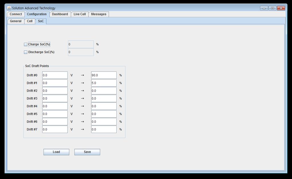
13 Configuration screen - Cell Configuration screen - SoC


14 Dashboard Screen Live cell screen

15 Message screen SAT BMS User Guide Rev01.
16 Appendix A. SAT BMS specification Item Spec. description Input / Output Input Power 12V, 4.2A Input Commu CAN bus, 2ea Site Controller, SBMS Bi-direction Nication RS-232c for debug Bi-direction Total Battery Voltage Input Data Total Current with Shunt Res. Input Reading Every Cell Voltage from SBMS, 24ch, on CANBUS Input Battery Temp from SBMS, 4ea Input Display Status of Running Output & LED Status of Fault Output GPIO for DC Contactor, 2ea Main, Pre-charge Output Controls GPIO for AC Contactor for PS, 2ea GPIO for FAN, 1ea Output Output Appendix B. SAT BMS protocol Item Protocol description Read/Write Unit Type Total Voltage Read V Float Cell Voltage Read V Float Total Current. Read A Float Temp. Read Float Information Controls General Control Configuration SoC (%) Read % Float SoC (Ah) Read Ah Float Charge limit Voltage Read V Float Discharge Limit Voltage Read V Float Charge limit Current Read A Float Discharge Limit Current Read A Float SoH Read % Float Cell Internal Resistance Read Ohm Float RMS Battery Current Read A Float Status Code Read Number Integer DC Main Contactor On/Off Read/Write On/Off Integer DC Pre-charge Contactor On/Off Read/Write On/Off Integer AC Contactor On/Off Read/Write On/Off Integer FAN On/Off Read/Write On/Off Integer Power-Down or Sleep Mode Read/Write Sleep/Active Integer General Cell Capacity Read/Write Ah Float Cell Number of Serial connection Read/Write Number Integer Bus-bar Resistance Read/Write Ohm Float Cell Number of Parallel connection(pack Read/Write Number Integer capacity, Ah) Shunt Resister value or type Read/Write Ohm TBD
17 Pack Voltage mismatch Threshold Read/Write V Float Voltage Cell Max Limit Voltage at charging Relay Read/Write V Float Open Cell Charge Re-Enable Time Relay Close Read/Write sec Float Cell Charge Release Voltage Relay Close Read/Write V Float Cell Max Charge Time Read/Write min Float Cell - Min Limit Voltage at discharge Relay Read/Write V Float Open Cell Discharge Re-Enable Time Relay Close Read/Write sec Float Cell Discharge Release Voltage Relay Close Read/Write V Float Cell Max Discharge Time Read/Write min Float Current Charge Current Limit Read/Write A Float Discharge Current Limit Read/Write A Float Reverse Current Sensor Read/Write FW/REV Integer Peak charge current limit Relay Open Read/Write A Float Charge current limit Relay Open when delay Read/Write A Float time s up Time delay before charge current limit Read/Write msec Integer Cell Balancing Cell - Balancing Delta voltage Balancing Gap. Read/Write V Float Cell Start Balancing Voltage Read/Write V Float Cell Minimum Balance Voltage Read/Write V Float Temp. Charging temp upper limit Read/Write Float Charging temp lower limit Read/Write Float Discharging temp upper limit Read/Write Float Discharging temp lower limit Read/Write Float Fan Enable Temp. Read/Write Float SoC SoC charged % Read/Write % Float SoC discharged % Read/Write % Float SoC Draft Point Read/Write %, Number TBD

 Slave")
18 Appendix C. SAT BMS Layout Master BMS(mm) Slave BMS(mm)
aentron Energy System 1 to 900 Vdc
 aentron Energy System 1 to 900 Vdc The aentron lithium-ion energy system enables the realisation of a modular and scalable lithium-ion battery solution. The management of large lithium-ion batteries systems
Integrated Battery Control System LBCS Step-by-Step Setup Guide
 Integrated Battery Control System LBCS Step-by-Step Setup Guide 1. Components of the System 2. Components of the System 3. LBCS Overview 4. Battery Connections 5. Sense Board Installation 6. Sense Board
Orion Jr. Purchasing Guide Rev. 1.2
 www.orionbms.com Orion Jr. Purchasing Guide Rev. 1.2 The Orion Jr. BMS is a low cost battery management system designed to manage low voltage lithium ion battery packs up to 48V nominal. The Orion Jr.
Nuvation High-Voltage BMS
 Nuvation High-Voltage BMS A utility-grade battery management system for energy storage Maximizes Battery Safety Increases Reliability and Uptime Data Analytics Gateway Enables Remote Management Battery
Energy Management System. Operation and Installation Manual
 Energy Management System Operation and Installation Manual AA Portable Power Corp 825 S 19 TH Street, Richmond, CA 94804 www.batteryspace.com Table of Contents 1 Introduction 3 2. Packing List 5 3. Specifications
BATTERY MANAGEMENT SYSTEM Master Slave configuration
 Rozna ulica 20, 6230 Postojna, Slovenia e-mail: info@rec-bms.com; www.rec-bms.com BATTERY MANAGEMENT SYSTEM Master Slave configuration Features: - robust and small design - Master + max 15 Slave combination
CANBus Data Interface Rev R Lithionics LLC
 NeverDie Battery Management System (BMS) CANBus Data Interface Rev. 8.0.00 R1 2018 Lithionics LLC If your BMS is equipped with the optional CANBus interface, you can connect the BMS to any CANBus compatible
Lithium power battery management system
 - 0 - Lithium power battery management system BMS005A specification - 0 - - 1 - Content 1 Product structure... 2 1.1 connection structure... 2 1.2 central controller... 3 1.3 voltage,current,insulation
Functional safety in BATTERY MANAGEMENT SYSTEMS
 Functional safety in BATTERY MANAGEMENT SYSTEMS LiTHIUM BALANCE history 2014 2015 2016 2011 2012 1 st OEM cust. in production 300 projects completed ISO 9001 certified 400 projects completed 500 projects
VIDI System Controller
 1 VIDI System Controller for OPUS DC Power Systems Product description VIDI is the advanced monitoring and control device for OPUS DC Power Systems. It delivers intelligence, an easy-to-use interface and
OPENUPS 6-34V Intelligent Uninterruptible Power Supply
 OPENUPS 6-34V Intelligent Uninterruptible Power Supply Installation Guide Version 1.0f P/N OPENUPS-06 Before you start Please take a moment and read this manual before you install the OPENUPS. Often times,
Contents 1 Warnings, Cautions, and Notes Description Features... 1
 EnCell Contents 1 Warnings, Cautions, and Notes... 1 2 Description... 1 3 Features... 1 3.1 STANDARD FEATURES... 1 3.2 FRONT PANEL FEATURES... 2 3.2.1 Display... 2 3.2.2 OK LED... 2 3.2.3 FAULT LED...
OPENUPS 6-34V Intelligent Uninterruptible Power Supply
 OPENUPS 6-34V Intelligent Uninterruptible Power Supply Installation Guide Version 1.0f Before you start Please take a moment and read this manual before you install the OPENUPS. Often times, rushing into
EMUS BMS mini User Manual v0.8
 EMUS BMS mini User Manual v0.8 1 Contents 1 System structure overview 5 2 Setting up the BMS 6 2.1 Battery cells installation................................ 6 2.2 Connecting temperature sensors............................
AC SMARTMOTION CONTROLLERs
 AC SMARTMOTION CONTROLLERs for and Generic Slave FAULT LIST and TROUBLESHOOTING (Rev. 2.4: March 2016) SME S.p.A. Via della Tecnica, n 40 36071 Arzignano (VI) - ITALY Phone:+39 (0444) 470511 Fax: +39 (0444)
Communication Protocol Reference Guide
 Communication Protocol Reference Guide 2018-10-08, Rev 20 Copyright 2018, Nuvation Energy Table of Contents 1 Introduction 1 11 About this Guide 1 2 Modbus Protocol Support 2 21 Overview 2 211 Modbus RTU
Safety Instructions 1-1 Avoid unintended Start General Description 2-2
 Contents Contents 1 Safety and precautions 1-1 Safety Instructions 1-1 Avoid unintended Start. 1-1 2 Introduction 2-1 General Description 2-2 3 Supported Configuration 3-1 Introduction 3-1 Fixed-speed
RT4F-110V/25A RECTIFIER
 The RT4F-110V/25A is a hot-pluggable switched mode rectifier (SMR) module designed to provide up to 25A of output current into a 110V nominal system. Examples of such systems are 60 cells lead acid (136V
EnCell Battery Cell Monitor
 EnCell Battery Cell Monitor Instruction Manual Model RCM15S12 NERC Compliant YO R U H T PA TO Z O R E W O D N M I T E enchargepowersystems.com sales@enchargepowersystems.com (888) 407.5040 Contents 1 Warnings,
PCU Supervisory module for the RM 1000 series
 Supervisory module for the RM 1000 series PCU 10.00 Microprocessor based control unit for supervision of internal and external functions in systems comprising RM 1000 rectifiers. Input power: 18-72V DC
VICTRON CCGX-SUPPORTED BATTERY MANAGEMENT SYSTEM WITH MPPT REMOTE ENABLE REC 1Q-16S
 Rozna ulica 20, 6230 Postojna, Slovenia e-mail: info@rec-bms.com; www.rec-bms.com VICTRON CCGX-SUPPORTED BATTERY MANAGEMENT SYSTEM WITH MPPT REMOTE ENABLE REC 1Q-16S Features: - robust and small design
200 VA bis VA 10 V bis 80 V 2 A bis 320 A. Source-Sink NL
 200 VA bis 3.120 VA 10 V bis 80 V 2 A bis 320 A NL AC, NL Series Interface overview RS-232 X USB X GPIB O LAN O System bus O Analog X Analog isolated O X Standard O Option / not available NL1V20C40 2-quadrant
Communication Protocol Reference Guide
 Communication Protocol Reference Guide 2017-12-22, Rev 20 Copyright 2017, Nuvation Energy Table of Contents 1 Introduction 1 11 About this Guide 1 2 Modbus Protocol Support 2 21 Overview 2 211 Modbus RTU
5KW Parallel Installation Guide
 5KW Parallel Installation uide 1. Introduction This inverter can be used in parallel with maximum 6 units. The supported maximum output power is 60KW/60KVA. 2. Parallel cable You will find the following
SUNRISE MEDICAL EDUCATION DEPARTMENT INFO. VR2 Codes Display and Code description
 VR2 Codes Display and Code description NOTE: A Complete Description Taken from the official PG Drives Engineering Manual is described on the next 3 pages TRIP CODE Details from Page listing Trip Code 1-1
1.Summarize. 1~ N (N 10) flexible, connecting method adopts N +1; Temperature can be set to have or have no depends on need. sensor. completely.
 flexible, connecting method adopts N +1; Temperature can be set to have or have no depends on need. sensor. completely.") 1.Summarize GTBMS005A-MC16 a battery management system consists of a colorful led screen with touch panel, a GTBMS005A-MC11 host controller, GTBMS005A-VT voltage temperature sampling modules and current
1.Summarize GTBMS005A-MC16 a battery management system consists of a colorful led screen with touch panel, a GTBMS005A-MC11 host controller, GTBMS005A-VT voltage temperature sampling modules and current
Operation Manual of Smart Battery Systems (SBS) with SmBus V1.1 support for 12.8V LiFePO4 battery pack (6.6Ah-100Ah)
 with SmBus V1.1 support for 12.8V LiFePO4 battery pack (6.6Ah-100Ah)") Operation Manual of Smart Battery Systems (SBS) with SmBus V1.1 support for 12.8V LiFePO4 battery pack (6.6Ah-100Ah) AA Portable Power Corp (http://www.batteryspace.com) Address: 860 S, 19 th St, Unit
Operation Manual of Smart Battery Systems (SBS) with SmBus V1.1 support for 12.8V LiFePO4 battery pack (6.6Ah-100Ah) AA Portable Power Corp (http://www.batteryspace.com) Address: 860 S, 19 th St, Unit
BMS: Installation Manual v2.x - Documentation
 Page 1 of 7 BMS: Installation Manual v2.x From Documentation This section describes how external peripheral devices are connected and additional functions of the BMS are used. I you have not done so already,
Evolion Toolbox Software Technical manual
 Evolion Toolbox Software Technical manual Contents 1. Introduction 4 2. Computer requirements 4 3. Software installation 4 4. Connecting 6 4.1 Single Connect 6 4.2 Bus connect (3 Evolion module example)
LTC4089/-5 DESCRIPTION
 LTC4089/-5 DESCRIPTION Demonstration circuit DC929A-A/B is a monolithic high voltage (6V-36V) switching buck regulator, USB Powerpath controller, and Li-Ion battery charger. It is based on the LTC4089/-5
Abstract. GLV User Manual 1
 GLV User Manual 1 Abstract This user manual is a high level document that explains all operational procedures and techniques needed to operate the GLV system in a safe and effective manner. Anyone operating
1PH RACK 19 SINGLE PHASE UPS Rev. 11 SR 6kVA 10kVA
 The SR series on line double conversion UPS with full time Digital Signal Processor control technology is the perfect solution for mission critical users who demand high reliability, availability and performance
-mbms. Battery Management SYSTEM OVERVIEW. Automation, Connectivity and Electrification of Mobile Machines ELECTRIFICATION SOLUTIONS
 Automation, Connectivity and Electrification of Mobile Machines ELECTRIFICATION SOLUTIONS SYSTEM OVERVIEW -mbms Battery-Management-System for Li-Ion Batteries Complete Solution Quick & Easy Integration
HCS-3600 / 3602 / 3604 Laboratory Grade & High RFI Immunity Switching Mode Power Supply with Rotary Encoder Control
 HCS-3600 / 3602 / 3604 Laboratory Grade & High RFI Immunity Switching Mode Power Supply with Rotary Encoder Control 1. INTRODUCTION User Manual This family of efficient, upgraded SMPS with small form factor,
BatteryCheck USER MANUAL BATTERY MANAGEMENT TECHNOLOGY THAT POWERS YOUR ADVENTURES.
 BatteryCheck USER MANUAL BM PRO - 19 Henderson Road, Knoxfield 3180, Victoria, Australia Phone +61 3 9763 0962 Fax +61 3 9763 8789 Email sales@teambmpro.com Web www.teambmpro.com BATTERY MANAGEMENT TECHNOLOGY
DTC P0AA6 - High Voltage Isolation Fault
 DTC P0AA6 - High Voltage Isolation Fault Product Family Orion BMS [Original] (24-180 Cell) Orion BMS 2 (24-180 Cell) Orion JR (16 Cell) Fault Supported YES YES NO FAULT DESCRIPTION This code is set when
Li-BMS V4. Modular Battery Management System. Datasheet. Updated in April 2017
 We electrify the future. Modular Battery Management System Updated in April 2017 LION Smart GmbH Daimlerstraße 15 85748 Garching www.lionsmart.com +49 89 360 363 200 Overview System Description and Structure
Gauge Design Configurations for High Charge / Discharge Rate Applications
 Gauge Design Configurations for High Charge / Discharge Rate Applications Thomas Cosby 1 Agenda Special pack applications High charge and discharge rates High capacity packs High cell count packs Hardware
ADC7520 SERIES. 1600W Battery Chargers and Power Supplies
 ADC7520 SERIES 1600W Battery Chargers and Power Supplies Wide output adjustment range 0 72VDC Analog control by external 0-5VDC voltage Temp.comp charging, sense as on option Power fail relay alarm Master-Slave
MAINTENANCE MANUAL. EDACS REDUNDANT POWER SUPPLY SYSTEM 350A1441P1 and P2 POWER MODULE CHASSIS 350A1441P3, P4, AND P5 POWER MODULES TABLE OF CONTENTS
 MAINTENANCE MANUAL EDACS REDUNDANT POWER SUPPLY SYSTEM 350A1441P1 and P2 POWER MODULE CHASSIS 350A1441P3, P4, AND P5 POWER MODULES TABLE OF CONTENTS SPECIFICATIONS*... 2 INTRODUCTION... 3 DESCRIPTION...
Trend-1 Vibration Data Logger. User Manual
 Trend-1 Vibration Data Logger User Manual Copyright College of Engineering-University of Basrah 2013 1 1. General Specifications 1.1 Features Thank you for being interested in purchasing Trend-1 Vibration
NTC/PTC- SIMULATION NTCS channel version
 NTC/PTC- SIMULATION 2-channel version MORE SAFETY AND CONTROL FOR YOUR DEVELOPMENT. Efficiency, reliability and safety of modern lithium ion batteries for electric vehicle drives strongly depend on the
Functional Testing of Electric Vehicle Battery Management Systems (BMS) using a PXI Platform Grant Gothing Project Engineer Bloomy Controls U.S.A.
 using a PXI Platform Grant Gothing Project Engineer Bloomy Controls U.S.A.") Functional Testing of Electric Vehicle Battery Management Systems (BMS) using a PXI Platform Grant Gothing Project Engineer Bloomy Controls U.S.A. The Challenge: Design and develop a flexible and cost-effective
Functional Testing of Electric Vehicle Battery Management Systems (BMS) using a PXI Platform Grant Gothing Project Engineer Bloomy Controls U.S.A. The Challenge: Design and develop a flexible and cost-effective
Torque Series LCD Remote Panel Installation/Operation Manual Model: TQ-DSP-12/24
 Torque Series LCD Remote Panel Installation/Operation Manual Model: TQ-DSP-12/24 Section Page Introduction 1 Materials Provided 1 I) Safety Instructions 1 A) Inverter Safety Instructions 1 B) Battery Safety
Green Engineering Pty Ltd
 Extra 2000 Lithium-Iron Phosphate Battery Backup Product Manual Information Version: 1.2 Green Engineering Pty Ltd 1300 200 959 info@greenengineering.com.au LEGAL NOTICES Copyright of Pylon Technologies
Contents. BMS icom Manual
 Contents 1. Introduction... 2 2. Safety Overview... 2 3. Package Contents... 3 4. Required Tools... 4 5. Installation Instructions... 6 Step 1: Mount BMS Unit... 6 Step 2: Clamp Setup... 6 Step 3: Sensing
PTDT V Quick Installation & Reference Guide. Ver Battery Management Solutions by. PowerDesigners
 PTDT+ 12-84V Quick Installation & Reference Guide Ver. 2.1 Battery Management Solutions by PowerDesigners Revision History Ver 1.0 12/13/04 BMS Ver 2.0 2/27/06 BMS Ver. 2.1 3/23/06 BMS New installation
Pack Manager Program System Design Document
 PACK MANAGER PROGRAM SYSTEM DESIGN DOCUMENT 1 Pack Manager Program System Design Document Latest Revision: 26 March 2014 Prepared by: Naing Htet Abstract This document describes the design of the software
Micro Instruments price list All pricing excludes 15%
 Micro Instruments price list All pricing excludes VAT @ 15% - 2019 Product Description Solar Smart R1 Solar MPPT regulator 12/24V - 20Amp with R2 799.00 5 Way Relay board R360.00 Ethernet + SNMP support
User Guide. TP3016M Series Switching Mode DC Power Supply
 User Guide TP3016M Series Switching Mode DC Power Supply 1 Introduction I. Quick Start 1.1 Front Panel Description 1.2 Pre-Checking 1.3 Quick Start 1.4 Output Checking II. Specifications 2.1 Major Specification
WIRELESS VEHICLE MONITORING SYSTEM (wvms) USER S MANUAL. Important Safety, Installation, Operation, and Maintenance Instructions. LesterElectrical.
 USER S MANUAL. Important Safety, Installation, Operation, and Maintenance Instructions. LesterElectrical.") WIRELESS VEHICLE MONITORING SYSTEM (wvms) USER S MANUAL Important Safety, Installation, Operation, and Maintenance Instructions LesterElectrical.com RATINGS LABEL The ratings label is located on the bottom
WIRELESS VEHICLE MONITORING SYSTEM (wvms) USER S MANUAL Important Safety, Installation, Operation, and Maintenance Instructions LesterElectrical.com RATINGS LABEL The ratings label is located on the bottom
Technical Data Sheets Uninterruptible Power Supply LP11 Series UPS kva
 GE Critical Power Technical Data Sheets Uninterruptible Power Supply LP11 Series UPS 3 5 6 8 10 kva GE Consumer & Industrial SA General Electric Company CH 6595 Riazzino (Locarno) Switzerland T +41 (0)91
SBS-S SERIES DC LOAD BANK USER MANUAL
 99 Washington Street Melrose, MA 02176 Phone 781-665-1400 Toll Free 1-800-517-8431 Visit us at www.testequipmentdepot.com SBS-S SERIES DC LOAD BANK USER MANUAL Models Covered SBS-4830S SBS-1110S SBS-2206S
D115 The Fast Optimal Servo Amplifier For Brush, Brushless, Voice Coil Servo Motors
 D115 The Fast Optimal Servo Amplifier For Brush, Brushless, Voice Coil Servo Motors Ron Boe 5/15/2014 This user guide details the servo drives capabilities and physical interfaces. Users will be able to
FES LCD Display Version 1.1
 FES LCD Display Version 1.1 LZ design d.o.o., Brod 3D, 1370 Logatec, Slovenia tel +386 59 948 898 info@lzdesign.si www.front-electric-sustainer.com Table of Content 1. Important notices... 3 1.1 Limited
POWERVAR SECURITY PLUS SERIES DETAILED UPS SPECIFICATION (8kVA 10kVA)
") POWERVAR SECURITY PLUS SERIES DETAILED UPS SPECIFICATION (8kVA 10kVA) A55-00017 SEC PLUS 8-10 KVA MAREKTING SPECS REV. A 9/10 8kVA, 10kVA POWERVAR Isolated On-Line UPS Specifications Index 1.0 General
POWERVAR SECURITY PLUS SERIES DETAILED UPS SPECIFICATION (8kVA 10kVA) A55-00017 SEC PLUS 8-10 KVA MAREKTING SPECS REV. A 9/10 8kVA, 10kVA POWERVAR Isolated On-Line UPS Specifications Index 1.0 General
CW2013. Low-Cost 1s Fuel Gauge IC with Low-SOC Alert. General Description. Features. Applications. Order Information
 CW2013 Low-Cost 1s Fuel Gauge IC with Low-SOC Alert Features System Side used Fuel Gauging 3% Maximum Total SOC Measurement Error 14 bit Delta Sigma ADC for Temperature and Cell Voltage Measurement Precision
Vector Drive - Troubleshooting Guide
 Haas Technical Documentation Vector Drive - Troubleshooting Guide Scan code to get the latest version of this document Translation Available The Haas Vector drive is the source of power for the spindle
DC M2 OLED Meter Instructions PN 1830 / PN 1832 / PN 1833 / PN 1834
 DC M2 OLED Meter Instructions PN 1830 / PN 1832 / PN 1833 / PN 1834 Installation Checklist Check for components included Read Warning and Cautions Read QuickStart Installation Guide for mounting instructions
I. PANEL DESCRIPTION... 1
 Table of Contents I. PANEL DESCRIPTION... 1 II. OPERATING INSTRUCTION... 7 1. MA OUTPUT... 7 1A. GENERAL OPERATION 4-20MA... 7 1B. SELECT 0-20MA OR 0-24MA... 8 1C. ENTER A VALUE LESS THAN 1... 9 2. % (PERCENTAGE)
High Voltage Battery Management System. NUV100 Datasheet , Rev. 1.9
 High Voltage Battery Management System NUV100 Datasheet 2017-12-15, Rev. 1.9 Nuvation Energy 2017 Table of Contents System Overview... 4 Nuvation BMS High-Voltage Stack Controller... 5 Hardware Overview...
Vector Drive - Troubleshooting Guide
 Haas Technical Documentation Vector Drive - Troubleshooting Guide Scan code to get the latest version of this document Translation Available The Haas Vector drive is the source of power for the spindle
BMS: Configuration Manual v2.x
 BMS: Configuration Manual v2.x From Documentation Contents 1 Introduction to configuration 2 Configuration management 3 General configuration 4 Cells configuration 5 Battery Pack configuration 6 Charger
RCB W Rack Mountable Front End Battery Charger. File Name:RCB-1600-SPEC Sicherheit ID
 Bauart gepruft Sicherheit egelma ge od o s be wac g www. tuv.com ID 2000000000 1600W Rack Mountable Front End Battery Charger File Name:-SPEC 2016-06-01 SPECIFICATION MODEL -12-24 BOOST CHARGE VOLTAGE(Vboost)(default)
Model INSTRUCTION MANUAL DIGITAL MULTIMETER
 Model 57040 INSTRUCTION MANUAL DIGITAL MULTIMETER SAFETY INFORMATION This multimeter has been designed according to IEC 1010 concerning electronic measuring instruments with an overvoltage category (CAT
Vector Drive - Troubleshooting Guide
 Haas Technical Documentation Vector Drive - Troubleshooting Guide Scan code to get the latest version of this document Translation Available The Haas Vector drive is the source of power for the spindle
Display Unit User Manual
 Display Unit User Manual Contents 3 Specifications 3 Display Specifications 3 Absolute Maximum Ratings 3 Characteristics 4 Get started 4 Wiring 5 Application interface 5 Firmware upgrade 8 Settings 9 Display
SBS-S SERIES DC LOAD BANK USER MANUAL Rev
 SBS-S SERIES DC LOAD BANK USER MANUAL Rev. 2.0 12-14 Test Equipment Depot - 800.517.8431-99 Washington Street Melrose, MA 02176 TestEquipmentDepot.com Contents OPERATING INSTRUCTIONS 1. Environment Requirement
RT12-240V/2.4kW Rectifier Specification
 The RT12-240V/2.4kW is a switched mode rectifier (SMR) module that delivers up to 2.4kW of output power (and up to 11A output current) into a 240V nominal DC system. The RT12 suits AC supply voltages between
CRAGG RAILCHARGER Instruction Manual for 10DTC-12V 20DTC-12V 30DTC-24V 40DTC-12V 60DTC-12V
 CRAGG RAILCHARGER for 10DTC-12V 20DTC-12V 30DTC-24V 40DTC-12V 60DTC-12V Contents 1 Warnings, Cautions, and Notes... 1 2 Description... 2 3 Features... 2 3.1 STANDARD FEATURES... 2 3.2 CHARGER REGULATION...
REGULATED DC POWER SUPPLIES.
 REGULATED DC POWER SUPPLIES. PRODUCT CATALOG 2011 PRODUCT CATALOG 2011 DelTA elektronika Table of contents: SM-series SM6000-Series 2 SM3300-Series 4 SM3000-Series 6 SM1500-Series 8 SM800-Series 10 ES-series
TSP-BCM48, TSP-BCM48A. Operating Instruction Manual. Page 1 of 13
 Battery Controller Module TSP-BCM24, TSP-BCM24A TSP-BCM48, TSP-BCM48A Operating Instruction Manual http://www.tracopower.com Page 1 of 13 Dimensions drawings: TSP-BCM24 & TSP-BCM48 Weight: 0.816lb Gewicht:
TRACKER 240 SERIES. Load Cell and Weighing Indicators. A Precision Measurement Instrument with Outstanding Features
 TRACKER 240 SERIES Load Cell and Weighing Indicators A Precision Measurement Instrument with Outstanding Features TRACKER 240 SERIES INDICATORS Ratiometric Measurement Tare and Auto Transducer Excitation
24/48V Battery Bank Ah High Cycling Long Life
 Outdoor Power Cabinets, 48V DC Free Cooled with Combined Air-Con. PreFactory assembled with 19 inch Power sub rack, 2 or 4 battery Shelf s, 3U DCAC Panel combined with rectifiers 2U or 4U Power Module
2 in 1 LAN Tester and Multimeter Model:
 2 in 1 LAN Tester and Multimeter Model: 72-8495 1 IMPORTANT SAFETY INFORMATION Please read these instructions carefully before use and retain for future reference. This instrument is designed and manufactured
Please take serious note of the following warnings:
 TPDIN-SC48-20 MPPT Solar Controller with Passive PoE Switch Wireless Base Stations and Client Devices Surveillance Cameras Remote Control Remote Lighting Off Grid Electronics Congratulations! on your purchase
Softstarters. Type PSTX Fieldbus communication, Fieldbus Plug Modbus RTU. 1SFC132092M0201 June SFC132092M0201 1
 Softstarters Type PSTX Fieldbus communication, Fieldbus Plug Modbus RTU 1SFC132092M0201 June 2017 1SFC132092M0201 1 1 Modbus RTU The Modbus protocol is a fieldbus protocol that provides full control and
TT /12b INSTALLATION INSTRUCTIONS. Introduction
 TT-1545 11/12b INSTALLATION INSTRUCTIONS Original Issue Date: 6/10 Model: 20-300 kw Generator Sets Market: Industrial Subject: Decision-Maker 3000 Controller Service Replacement Kit GM75376 Introduction
Technical manual for HP8480 Main battery switch with current monitor. + Low power output for rain light. + Battery discharge warning output.
 Technical manual for HP8480 Main battery switch with current monitor. + Low power output for rain light. + Battery discharge warning output. Date: 2018-03-27\KT Page 1 of 10 Table of content 1) Product
Electronic Loads. Installation & Operation Manual EL101/300 EL1000
 Electronic Loads Installation & Operation Manual EL101/300 EL1000 09/2015 Electronic Loads -1- CAUTION Prevent the inputs of the device from electrostatic discharge This may damage the device. Do not connect
NUV300 Datasheet. Nuvation BMS Low-Voltage Battery Controller , Rev Copyright 2018, Nuvation Energy
 NUV300 Datasheet Nuvation BMS Low-Voltage Battery Controller 2018-10-08, Rev. 2.0 Copyright 2018, Nuvation Energy Table of Contents 1. System Overview......................................................
SIRIUS CAPACITOR MODULE User Manual. Model number: A-1.7C-M-SD-G Version 1.0; Release Date: April 2018
 SIRIUS CAPACITOR MODULE User Manual Model number: 3550-48-A-1.7C-M-SD-G Version 1.0; Release Date: April 2018 Introduction The Sirius Capacitor Module ( Sirius ) is supercapacitor-based storage that uses
BBDC-02R. Quick Start Guide Rev 1.2 9/29/08
 BBDC-02R Quick Start Guide Rev 1.2 9/29/08 BBDC-02R Dual Battery Controller with ATX Power Supply The BBDC-02R Quick Start Guide is provided to assist new users with basic interconnect procedures and to
Electric Vehicle Management System V3
 http://www.zeva.com.au Electric Vehicle Management System V3 + Table of Contents Multifunctional, integrated control system for your EV Main Contactor 12VDC Aux Contactor Ground Charge Enable Introduction
KEPCO SINGLE OUTPUT, 1U SIZE, 100 WATT HOT SWAP PLUG-IN POWER SUPPLIES TABLE 1. OUTPUT RATINGS AND SPECIFICATIONS, HSF-1UR 100W SERIES
 INSTRUCTION MANUAL KEPCO An ISO 9001 Company. KEPCO SINGLE OUTPUT, 1U SIZE, 100 WATT HOT SWAP PLUG-IN POWER SUPPLIES HSF-1UR 100W SERIES I INTRODUCTION The Kepco HSF-1UR 100 Watt Series hot swappable,
1. Installation. 2. Configuration - Operation. 3. Specifications. Safety
 Safety 1. Installation 1.1 OP_ext: Services 1.2 Driver Card Installation 1.3 Sensor Types 1.4 Sensor Wiring 1.5 Controller Wiring 2. Configuration - Operation 2.1 Replaces ph Sensor 2.2 AS -Flex Series
RT4F-48V/50A-WAC RECTIFIER
 The RT4F-48V/50A-WAC is a switched mode rectifier (SMR) module designed to provide up to 58A of output current into a 48V nominal system, over a wide range of AC input voltage. This rectifier has been
Innovative Circuit Technology Ltd.
 Innovative Circuit Technology Ltd. Modular Power Series INSTRUCTION MANUAL 855-340-000 Models: Modular Power Shelf with Intelligent Controller 12V 50A Power Module ICT700-12PM 24V 25A Power Module ICT700-24PM
Airtalk I/O Extender
 Airtalk I/O Extender for Stratomaster Enigma, Odyssey and Voyager EFIS systems User manual Document date 21/6/2007 General The I/O Extender is a small unit designed to extend the I/O interface capabilities
3200W Rack Mountable Front End Battery Charger. DBR-3200 is a 3200W single output AC/DC front-end charger in 1U low profile with high power density, 3
 Bauart gepruft Sicherheit egelma ge od o s be wac g www. tuv.com ID 2000000000 3200W Rack Mountable Front End Battery Charger DBR-3200 is a 3200W single output AC/DC front-end charger in 1U low profile
TD-700 FLUOROMETER SERVICE MANUAL
 TD-700 FLUOROMETER SERVICE MANUAL July 1996 CONTENTS Page Section 1 INTRODUCTION 2 Section 2 PRELIMINARY CHECKS 3 Section 3 TROUBLESHOOTING GUIDE 5 A. Lamp (Fluorescent) 5 B. Lamp Heater 7 C. Fan 8 D.
SCM030. MPPT Solar System Controller With. DC to DC Booster Input. Installation & Operating Instructions
 SCM030 MPPT Solar System Controller With DC to DC Booster Input Installation & Operating Instructions ABOUT THIS MANUAL These operating instructions come with the product and should be kept with it as
REMOTE METER USER MANUAL KAMPPTRC
 REMOTE METER USER MANUAL K A M P P T R C KAMPPTRC 1. PRODUCT FEATURES 1) LCD screen. 2) Can display up to 10 parameters and states. 3) Has a low power consumption with BLE4.0 feature for strong communication
This document describes the procedure for doing a power trace on the SM5 and Gauntlet Stepmills.
 SM5/Gauntlet Stepmill Power Trace Applies to: SM5 (150005) + Gauntlet (150015) This document describes the procedure for doing a power trace on the SM5 and Gauntlet Stepmills. Latest Rev. Warning: the
RT4F-120V/20A-WAC RECTIFIER
 The RT4F-120V/20A-WAC is a switched mode rectifier/charger module designed to provide up to 20A of output current into a 120V nominal system. This charger has been designed for use in conjunction with
Power Supplies. Chapter The McGraw-Hill Companies, Inc. All rights reserved. Mike Meyers CompTIA A+ Guide to Managing and Troubleshooting PCs
 Power Supplies Chapter 10 Overview In this chapter, you will learn how to Explain the basics of electricity Describe the details about powering the PC Install and maintain power supplies Understand power-supply
MPCR Series DeviceNet Technical Manual TDMPCRDNTM2-0EN 01/08 Subject to change without notice
 MPCR Series DeviceNet Technical Manual Table of Contents MPCR Series Introduction... 3 Product Overview... 3 About DeviceNet... 4 Overview... 4 MPCR DeviceNet Features... 4 Cabling and Drop Line Lengths
EV Controls user Guide
 EV Controls user Guide Copyright EV Controls Table of Contents Introduction... EV Controls System Features... General guidelines for installation... Inverter Electrical Pinout Sheet... Drive Inverter Connections...
DPM Bi-directional Digital DC Power Meter with built-in USB data logger & adapter External shunt model. User Manual
 DPM-3321 Bi-directional Digital DC Power Meter with built-in USB data logger & adapter External shunt model User Manual Bi-Directional DC Power Meter with built-in USB data logger & adapter. The new DPM-3321
Thanks for buying our product. Specialty of IM-2DT
 High Precision 2-Axis Digital Electronic Inclinometer IM-2DT User s Guide The contents of this manual could be different according to the software version and it can be changed without notice. Please use