PCR-300_500_800_e.book 1 ページ 2007年2月28日 水曜日 午後7時10分 Owner s Manual
|
|
|
- Oswin Lang
- 5 years ago
- Views:
Transcription


1 Owner s Manual
2 Contents Names of things and what they do...4 Panel... 4 Side panel... 7 Using control maps...8 What is a control map?... 8 Control maps and the current memory... 8 Switching control maps... 9 Saving a control map... 9 Receiving a control map from your computer (Bulk Receive) Saving control map data on your computer (Bulk Transmit) Protecting the control maps Using PCR Editor...14 Setting the MIDI ports Windows users Mac OS X users Explanation of the menus File menu Edit menu Communication menu Options menu Help menu Keyboard shortcuts Explanation of each window Main window Message assignment window Using PCR Editor to assign MIDI messages Assigning a MIDI message Viewing the assigned MIDI messages Transferring data between PCR Editor and the PCR Sending Receiving Saving a control map on your computer Loading a control map Loading a memory set as a control map Importing a memory set Parameter setting items NO ASSIGN Channel Message System Realtime/F6 [F6/F8/FA/FB/FC/FF] System Ex. [F0...F7] Free Message [...] Tempo Playing (Play mode) Go ahead and play Convenient performance functions Selecting the current channel (MIDI transmit channel) MIDI channel Selecting sounds (Program Change/Bank) Program Change Bank Select Selecting the Lower and Upper sounds Selecting the Lower sound Selecting the Upper sound Layering two sounds (Dual) Playing two sounds in combination (Split) Employing performance dynamics (Velocity) Specifying a fixed velocity (Key Velocity) Changing the keyboard touch (Velocity Curve) Sending the current value of all controllers (Snapshot) Muting the controller values (PRM MUTE) When stuck notes occur (Panic)
3 Settings (Edit mode)...41 Assigning MIDI messages on the PCR keyboard Note assign Aftertouch assign Control change assign Program change assign Tempo assign RPN/NRPN assign System exclusive assign Convenient functions Copy assignment Canceling an assignment (NO ASSIGN) System settings...68 Clock settings F8 Clock On/Off F8 Clock Default Tempo F8 Clock Port Set Keyboard settings Keyboard Velocity Curve Keyboard Port Set Keyboard Aftertouch Curve Pad settings Pad Velocity Curve Pad Aftertouch Curve MIDI settings MIDI I/F Switch MIDI Merge Destination Advanced Driver Switch Control map settings Startup Memory VALUE knob settings VALUE encoder Other settings Dynamic Mapping/V-LINK H-activity On/Off Factory Reset Troubleshooting Problems with connections Deleting the USB driver Problems while using the PCR Appendix Two MIDI ports Connecting the PCR directly to a sound module Control map list MIDI implementation chart Main specifications Index Before using this unit, carefully read the sections entitled: USING THE UNIT SAFELY and IMPORTANT NOTES (separate sheet). They provide important information concerning the proper operation of the unit. Additionally, in order to feel assured that you have gained a good grasp of every feature provided by your new unit, Owner s manual should be read in its entirety. The manual should be saved and kept on hand as a convenient reference. * All product names mentioned in this document are trademarks or registered trademarks of their respective owners. Copyright 2007 ROLAND CORPORATION All rights reserved. No part of this publication may be reproduced in any form without the written permission of ROLAND CORPORATION. 3
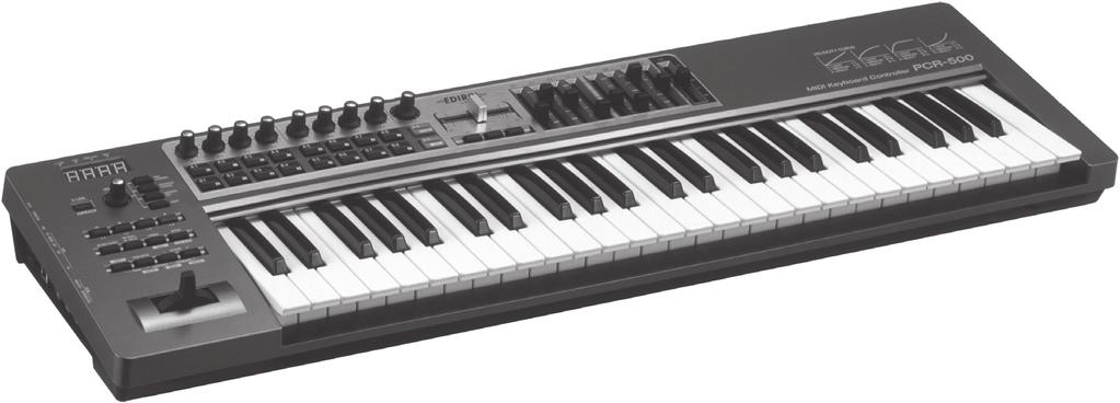
4 Names of things and what they do Panel fig.panel-left.eps Display This shows a variety of information, such as the current state. Indication Alphanumeric characters DYNAMIC MAPPING USB DATA OUT HEX Summary When you operate a controller, the value of the parameter assigned to that controller is briefly displayed. Information such as MIDI channels and program changes are also displayed. This will light when DYNAMIC MAPPING is active. This will light when the PCR is connected to your computer via USB. This will blink when a MIDI message is transmitted from USB or MIDI OUT. This will light when the value shown in the display is a hexadecimal value. * The display will dim if you leave the PCR without operating it for several seconds. * The explanations in this manual include illustrations that depict what should typically be shown by the display. Note, however, that your unit may incorporate a newer, enhanced version of the system, so what you actually see in the display may not always match what appears in the manual. [DYNAMIC MAPPING] button, [V-LINK] button When you press the [DYNAMIC MAPPING] button, DYNAMIC MAPPING or V-LINK will turn on. The function of the [DYNAMIC MAPPING] button is specified by the System setting DYNAMIC MAPPING/V-LINK (p. 81). DYNAMIC MAPPING Dynamic Mapping is an extended function for future use. For details, refer to the Roland website. V-LINK V-LINK ( ) is a function that allows music and images to be performed together. By using MIDI to connect two or more V-LINK compatible devices, you can easily enjoy a wide range of visual effects that are linked to the expressive elements of a music performance. 4
5 Names of things and what they do VALUE knob By turning the VALUE knob you can change the value of the MIDI CHANNEL, PROGRAM CHANGE, CONTROL MAP, or USER. In Edit mode, use this knob to select the item that you want to edit. [MIDI CHANNEL] button After pressing the [MIDI CHANNEL] button so it s lit, you can turn the VALUE knob to specify the channel on which the keyboard and bender will transmit messages. (-> Selecting the current channel (MIDI transmit channel) (p. 33)) [PROGRAM CHANGE] button After pressing the [PROGRAM CHANGE] button so it s lit, you can turn the VALUE knob to transmit a program change message on the current channel. (-> Selecting sounds (Program Change/Bank) (p. 34)) [CONTROL MAP] button After pressing the [CONTROL MAP] button so it s lit, you can turn the VALUE knob to switch among control maps stored in the PCR. (-> Switching control maps (p. 9)) [USER] button After pressing the [USER] button so it s lit, you can turn the VALUE knob to change the value of a user-assigned parameter. (-> VALUE knob settings (p. 80)) Controllers [L1] [L4] (buttons) You can assign the desired MIDI messages to these buttons. (-> Assigning a MIDI message (p. 20)) [AFTERTOUCH] button This specifies whether the keyboard will (ON) or will not (OFF) transmit aftertouch messages. [DUAL/SPLIT] button This switches between Dual mode and Split mode. (-> Layering two sounds (Dual) (p. 37)) (-> Playing two sounds in combination (Split) (p. 37)) [LOWER] button, [DATA] button Use this button when you want to play or make settings for the Lower part. If the [LOWER] button is lit, the keyboard (notes and aftertouch), bender lever (pitch bend, modulation), foot pedal messages, and program change messages will be transmitted on the current channel specified for the Lower part. (-> Selecting the Lower and Upper sounds (p. 36)) [UPPER] button, [CHK SUM] button Use this button when you want to play or make settings for the Upper part. If the [UPPER] button is lit, the keyboard (notes and aftertouch), bender lever (pitch bend, modulation), foot pedal messages, and program change messages will be transmitted on the current channel specified for the Upper part. (-> Selecting the Lower and Upper sounds (p. 36)) [EDIT] button Use this button to assign MIDI messages to the controllers or to make system settings. (-> Assigning MIDI messages on the PCR keyboard (p. 41)) (-> System settings (p. 68)) [PRM MUTE] button, [ENTER] button Use this to mute controller message output. When you re not in Play mode, you can use this as the [ENTER] button. OCTAVE [-]/[+] buttons, [BACK] button, [CANCEL] button Use these buttons to raise or lower the octave of the keyboard. When you re not in Play mode, you can use these as the [BACK] button, which returns you to the previous setting, and the [CANCEL] button, which cancels the setting. Bender lever, [BEND] and [MOD] controller You can use this to modify the pitch or to apply vibrato. You can also assign the desired MIDI messages to this controller. (-> Assigning MIDI messages on the PCR keyboard (p. 41)) 5
6 Names of things and what they do fig.panel-top.eps Controllers [R1] [R9] (knobs) You can assign the desired MIDI messages to these knobs. (-> Assigning a MIDI message (p. 20)) Controllers [A1] [A9], [B1] [B9] (pads) You can assign the desired MIDI messages to these pads. (-> Assigning a MIDI message (p. 20)) The force with which you press these controllers can be used to transmit a corresponding velocity value or aftertouch value. When you re not in Play mode, you can use these buttons as [0] [9] and [A] [F] buttons to enter numeric values. [DECIMAL] button When you re not in Play mode, you can press this button to switch to decimal input mode (p. 64). When you re in Play mode, this button will function as a conventional controller [A9] [HEX] button When you re not in Play mode, you can press this button to switch to hexadecimal input mode (p. 64). When you re in Play mode (p. 32), this button will function as a conventional controller [B9]. Controllers [H1], [H2] (crossfader) You can assign the desired MIDI messages to this crossfader. (-> Assigning a MIDI message (p. 20)) Controllers [C1] [C3] (buttons) You can assign the desired MIDI messages to these buttons. (-> Assigning a MIDI message (p. 20)) Controllers [S1] [S9] (sliders) You can assign the desired MIDI messages to these sliders. (-> Assigning a MIDI message (p. 20)) 6
7 Names of things and what they do Side panel fig.panel-side.eps MIDI MERGE switch This switches the MIDI IN message Merge function on/off. (-> MIDI Merge Destination (p. 77)) MIDI IN/OUT connectors You can connect these to the MIDI connectors of other MIDI devices in order to transmit and receive MIDI messages. (-> MIDI settings (p. 76)) Controllers [P1], [P2] (foot pedals) You can connect suitable pedals to these jacks and use them as controllers DC IN jack You can connect a separately available AC adaptor (p. 92) to this jack. If you wish to purchase an AC adaptor, please contact your dealer. Power switch HOLD EXPRESSION You can connect a separately available pedal switch (DP-2, BOSS FS-5U) here and use it as a hold pedal. You can connect a separately available expression pedal (EV-5, EV-7) here and use it to control the tone or volume in real time. You can assign the desired MIDI messages to these controllers. (-> Assigning a MIDI message (p. 20)) * Use only the specified expression pedal. By connecting any other expression pedals, you risk causing malfunction and/or damage to the unit. DC OFF USB Power turned on when using the AC adaptor Power switched off Power turned on when a USB cable is connected You can use the USB (i.e., bus power) setting if the PCR-300/500/ 800 is connected to your computer via a USB cable. The power will be supplied from the computer via the USB cable. If you want to use the PCR on bus power, set the power switch to the USB position. * With some computers, the PCR may not operate on bus power. If so, you ll need to use the separately available AC adaptor (p. 92). 30 Security slot ( ) 26 USB connector Use this if you re connecting the PCR to your computer via a USB cable. 7
8 Using control maps What is a control map? The PCR-300/500/800 have fifty fully assignable controllers; you can freely assign any MIDI message to each of these controllers. The MIDI settings assigned to the controllers are collectively called a control map. This is the same as what was called a memory set on previous models of the PCR series. For details on how to assign MIDI messages to controllers, refer to Using PCR Editor (p. 14) or Assigning MIDI messages on the PCR keyboard (p. 41). MIDI settings that are assigned to the controllers (i.e., the control map) can be stored in the PCR s own memory or in DAW software on your computer. Simply by switching control maps, you can control a wide range of applications. You can also download the latest control maps from the Roland website and load them into the PCR. Memory Sets and Control Maps The memory sets in earlier models of the PCR series are now called control maps on the PCR-300/500/800. Using the PCR Editor version 2 software included with this product, you can import memory sets and use them as control maps. For details, refer to Using PCR Editor (p. 14). Control maps and the current memory About the PCR s memory fig.currentmemory-e.eps Control maps SONAR Logic Cubase : : etc... The PCR-300/500/800 holds sixteen control maps in its internal memory. In order to use a control map, you must copy it into a location called the current memory. Any changes you make to the contents of the current memory will be lost when you turn off the power. If you want to keep the changes you ve made to the current memory, refer to Saving a control map (p. 9). You can use the Startup Memory (p. 79) to specify which control map should be loaded into current memory when the power is turned on. Current Memory 8
9 Using control maps Switching control maps When the PCR-300/500/800 is shipped from the factory, it contains sixteen control maps. By switching among these control maps, you can quickly select control maps that are suitable for a wide variety of software. For details on the memory numbers of these control maps and their factory settings, refer to Control map list (p. 90). fig.h-memoryset.eps 1 Press the [CONTROL MAP] button. The [CONTROL MAP] button will light. The display will indicate the currently selected memory number. Saving a control map If you want to keep the changes you ve made to the current memory, use the following procedure to save the control map. You can save the control map in memory numbers 1 F. You can t save to memory number 0. * If you ve changed the settings of the current memory, be sure to SAVE if you want to keep your changes. fig.h-edit.eps 1 Press the [EDIT] button so it s lit. 2 Turn the [VALUE] dial to select the memory number you want to call up. fig.d-edit.eps The display will indicate EDIT. fig.d-save.eps 2 Turn the VALUE knob to make the display indicate SAVE. You can also switch control maps using the following method. 1. Press the [EDIT] button so it s lit. The display will indicate EDIT. 2. Press the [CONTROL MAP] button. It will light, and the display will indicate the currently selected memory number. 3. Use controllers [A1] [A8], [B1] [B8], or the VALUE knob to specify the memory number you want to call up. 4. Press the [ENTER] button. fig.d-protect.eps 3 Press the [ENTER] button. * If the display indicates PTC, the Protect setting is ON, and you ll be unable to save the memory. Turn the Protect setting OFF, and repeat the procedure from step 1. (-> Protecting the control maps (p. 13)) 4 Use the VALUE knob or controllers [A2] [A8] and [B1] [B8] to specify the memory number 1 F in which you want to save the control map. The specified memory number will blink in the display. 5 Press [ENTER] to save the control map. * If you press another button instead of the [ENTER] button, the Save operation will be cancelled. 9
10 Using control maps Receiving a control map from your computer (Bulk Receive) The PCR-300/500/800 can receive control map data in the form of a bulk dump. If you want control map data you ve created using PCR Editor to be received into the PCR s current memory, you ll need to make settings in PCR Editor so that the PCR will be ready to receive a bulk dump. If you want the PCR to receive this data as messages from your DAW software, you ll need to make settings on the PCR keyboard so that it will be ready to receive a bulk dump. Here we ll explain how to make settings on the PCR keyboard so that it will be able to receive a bulk dump. fig.h-edit.eps 1 Press the [EDIT] button so it s lit. For more about PCR Editor, refer to Using PCR Editor (p. 14). For details on how to receive a control map from PCR Editor, refer to Transferring data between PCR Editor and the PCR (p. 22). 4 Verify that the display indicates BLR (Bulk Receive), and then press the [ENTER] button. If the display indicates BLT (Bulk Transmit), use the VALUE knob to make it indicate BLR (Bulk Receive). 5 Use the VALUE knob or the controllers to choose the reception method. Choose the method that s appropriate for the data you ll be receiving. Controller Item Display Explanation [A1 (0)] SINGLE BULK [A2 (1)] ALL BULK One control map will be received. The received data will overwrite the current memory. Memories 1 F will not be affected. Data for all fifteen control maps will be received. The received data will overwrite internal memories 1 F. fig.d-rsbulk-wait.eps 6 Verify that the display indicates the correct choice, and press the [ENTER] button. The rightmost digit of the display will blink, and the PCR will wait for bulk data to arrive. fig.d-edit.eps The display will indicate EDIT. fig.d-bulk.eps 2 Turn the VALUE knob to make the display indicate BULK. About the display in Bulk mode Receive/Transmit fig.d-bulkr.eps 3 Press the [ENTER] button. BLR will blink in the display (Bulk Receive). Receive Transmit SINGLE BULK / ALL BULK SINGLE BULK ALL BULK Transmitting/Receiving/Waiting Receiving Receive Transmit Waiting Waiting (blinking) (blinking) Transmitting 10
11 Using control maps 7 Operate PCR Editor or your DAW software to transmit the control map data. Select EDIROL PCR as the MIDI output device for PCR Editor or your DAW software. For details on how to make this setting in your DAW software, refer to the owner s manual for the DAW software you re using. fig.d-end.eps 8 When the PCR has finished receiving the control map data, the display will indicate END. Press the [ENTER] button to complete the operation. Error indication If the data was not received correctly, ERR will be blinking in the display. If this occurs, press the [CANCEL] button and perform the procedure again from step 1. Control map data received as Single Bulk will be loaded into the current memory, meaning that it will be lost when you turn off the power. However, if you save this control map into one of the internal memories, you won t need to re-transmit it to the PCR. Refer to Saving a control map (p. 9). 11
12 Using control maps Saving control map data on your computer (Bulk Transmit) The PCR-300/500/800 can transmit control map data to your DAW software in the form of a bulk dump. In order to transmit a control map you ve edited on the PCR keyboard to PCR Editor or other software you re using, you ll need to make settings on the PCR to make it transmit the bulk data. fig.h-edit.eps 1 Press the [EDIT] button so it s lit. For more about PCR Editor, refer to Using PCR Editor (p. 14). For details on how to transmit a control map from PCR Editor, refer to Transferring data between PCR Editor and the PCR (p. 22). Controller Item Display Explanation [A1 (0)] BULK RECEIVE Receive bulk data [A2 (1)] BULK TRANSMIT Transmit bulk data 5 Press the [ENTER] button. 6 Use the VALUE knob or controllers to choose the type of transmission. Choose the type of data you want to transmit. Controller Item Display Explanation [A1 (0)] SINGLE BULK The control map data of the current memory will be transmitted. fig.d-edit.eps The display will indicate EDIT. fig.d-bulk.eps 2 Turn the VALUE knob to make the display indicate BULK. fig.d-bulkr.eps 3 Press the [ENTER] button. BLR will blink in the display (Bulk Receive). fig.d-bulkt.eps 4 Turn the VALUE knob to make the display indicate BLT (Bulk Transmit). Alternatively, you can press controller [A2 (1)] instead of using the VALUE knob. [A2 (1)] ALL BULK Data for all fifteen control maps in internal memory (memories 1 F) will be transmitted. fig.d-tsbulk-wait.eps 7 Check the indication in the display, then press the [ENTER] button. The rightmost digit of the display will blink, and the PCR will wait to transmit bulk data. 8 Put PCR Editor or your DAW software in recording mode, and then press the PCR s [ENTER] button. Data transmission will begin. Choose EDIROL PCR 2 as the MIDI input port for PCR Editor or your DAW software. For details on how to make this setting in your DAW software, refer to the owner s manual for the software you re using. fig.d-end.eps 9 When the PCR has finished transmitting the control map data, the display will indicate END. Press the [ENTER] button to complete the operation. You ll also need to stop recording on your DAW software. 12
13 Using control maps Protecting the control maps By turning the Protect setting on, you can protect the control map data from being accidentally overwritten. This will disable All Bulk reception (p. 10) and Save (p. 9) operations, protecting your valuable data from being overwritten. fig.h-edit.eps 1 Press the [EDIT] button so it s lit. The Protect on/off setting is remembered even when the PCR is powered off. fig.d-edit.eps The display will indicate EDIT. fig.d-protect.eps 2 Turn the VALUE knob to make the display indicate PTC. 3 Check the indication in the display, then press the [ENTER] button. The display will indicate the current protect status. Controller Item Display Explanation [A1 (0)] PROTECT OFF Control map data in internal memory can be rewritten. [A2 (1)] PROTECT ON Control map data in internal memory cannot be rewritten. 4 Use the VALUE knob to choose the desired setting, and press the [ENTER] button. 13

14 Using PCR Editor PCR Editor Ver. 2 is an application that lets you use your computer to create control maps (called memory sets on earlier models of the PCR series) for the EDIROL PCR series. fig.controller.eps The PCR-300/500/800 has a total of fifty controllers: [R1] [R9], [S1] [S9], [A1] [A9], [B1] [B9], [C1] [C3], [L1] [L4], [H1] [H2], [P1] [P2], [BEND], [MOD], and [AFTERTOUCH]. You can freely assign the MIDI message that will be transmitted by each of these controllers. Although it is possible to make MIDI message assignments on the PCR itself (-> Assigning MIDI messages on the PCR keyboard (p. 41)), it s easiest to use PCR Editor, since this allows you to easily assign messages in a graphical screen that resembles the PCR s panel. The fifty messages assigned to the controllers are collectively called a control map. PCR Editor Ver. 2 lets you edit control map data and transfer it between the PCR and your computer, and also save or load control map settings as SMF data. Setting the MIDI ports In order to transfer control maps between PCR Editor and the PCR, you ll need to specify the MIDI ports that PCR Editor is to use. * The explanation that follows is for when the PCR is connected via USB. If you re using a MIDI connection, specify the MIDI input port and MIDI output to which your PCR is MIDI-connected instead of EDIROL PCR 2 and EDIROL PCR. What are MIDI ports? Input ports Input port EDIROL PCR MIDI IN EDIROL PCR 1 EDIROL PCR 2 Explanation Receives data that arrives at the PCR s MIDI IN connector. Receives data from the PCR s sliders, knobs, and buttons that are assigned to PORT 1. Receives data from the PCR s sliders, knobs, and buttons that are assigned to PORT 2. If you re receiving bulk data from the PCR, choose PCR 2 as the input port. The output destination for the MIDI messages sent when you operate the PCR s sliders, knobs, and buttons can be specified independently for each controller. For details, refer to Two MIDI ports (p. 88). Output ports Output port EDIROL PCR MIDI OUT EDIROL PCR Explanation Transmits MIDI messages to the device connected to the PCR s MIDI OUT connector. Transmits MIDI messages to the PCR. If you re sending bulk data to the PCR, choose PCR as the output port. In order to send a control map you ve created in PCR Editor to the PCR so that it can be used, you ll need to select PCR as the output port. 14

![3 In PCR Editor, choose [Options]-[MIDI Devices]. fig.winmidiport-e.eps 4 In the MIDI Devices dialog box, make the MIDI device settings shown in the illustration. 5 Click [OK] to close the dialog box.](/docs-images/81/82627167/images/15-1.jpg "Mac OS X users If you have not yet installed PCR Editor in your computer, install it now as described in the included setup guide.")
15 Using PCR Editor Windows users If you have not yet installed PCR Editor in your computer, install it now as described in the included setup guide. 1 Use a USB cable to connect the PCR to your computer, then switch on the PCR s power. 2 In Windows, choose [Start]-[All Programs]-[PCR Editor V2]-[PCR Editor 2] to start up PCR Editor. 3 In PCR Editor, choose [Options]-[MIDI Devices]. fig.winmidiport-e.eps 4 In the MIDI Devices dialog box, make the MIDI device settings shown in the illustration. 5 Click [OK] to close the dialog box. Mac OS X users If you have not yet installed PCR Editor in your computer, install it now as described in the included setup guide. 1 Use a USB cable to connect the PCR to your Mac, then switch on the PCR s power. 2 From the Mac Finder, open the [Applications]-[PCR Editor V2] folder, and double-click PCR Editor V2 to start up PCR Editor. 3 In PCR Editor, choose [Options]-[MIDI Devices]. fig.macmidiport-e.eps 4 In the MIDI Devices dialog box, make the MIDI device settings shown in the illustration. 5 Click [OK] to close the dialog box. * Microsoft and Windows are registered trademarks of Microsoft Corporation. * The screen shots in this document are used in compliance with the guidelines of the Microsoft Corporation. * Windows is known officially as: Microsoft Windows operating system. * Apple and Macintosh are registered trademarks of Apple Computer, Inc. * Mac OS is a trademark of Apple Computer, Inc. 15
16 Using PCR Editor Explanation of the menus File menu Communication menu Menu New Open Save Save As Import Memory Set Export Assign List View Assign List Explanation Creates a new control map. In the new control map, all controllers will be set to NO AS- SIGN. Loads a control map that was saved in SMF format. For details, refer to Loading a control map (p. 23). Saves the control map currently being edited by overwriting the original SMF. Saves the control map currently being edited in SMF format with the name you specify. For details, refer to Saving a control map on your computer (p. 23). Loads a memory set created in PCR Editor version 1 as a version 2 control map. Exports an HTML-format list of the messages assigned to each controller of the control map currently being edited. * The HTML file created by this command cannot be loaded by means of [File]-[Open]. Displays an HTML-format list of the messages assigned to each controller of the control map currently being edited. Menu Transmit Receive Options menu Menu MIDI Devices Show Messages Explanation Transmits the control map currently being edited to the current memory of the PCR keyboard. For details, refer to Transferring data between PCR Editor and the PCR (p. 22). Receives the current memory of the PCR into PCR Editor. For details, refer to Transferring data between PCR Editor and the PCR (p. 22). Explanation Specifies the MIDI ports used to communicate with the PCR keyboard. For details, refer to Setting the MIDI ports (p. 14). Shows the MIDI message settings assigned to each controller in the main window of PCR Editor. For details, refer to Viewing the assigned MIDI messages (p. 21). Edit menu Menu Copy Paste NO ASSIGN Explanation Copies the setting of the selected controller to the clipboard. Pastes the setting from the clipboard to the selected controller. Sets the assignment of the selected controller to NO ASSIGN. Help menu Menu PCR Editor Help Opens the online manual. Explanation 16
17 Using PCR Editor Keyboard shortcuts You can use the following keyboard shortcuts in PCR Editor. Command Windows Macintosh [File] [New] Ctrl + N Command + N [File] [Open] Ctrl + O Command + O [File] [Save] Ctrl + S Command + S [File] [Save As] Ctrl + Shift + S Command + Shift + S [File] [Exit] Alt + F4 Command + Q [Edit] [Copy] Ctrl + C Command + C [Edit] [Paste] Ctrl + V Command + V [Edit] [NO ASSIGN] Del Del Next controller Ctrl + F Command + F Previous controller Ctrl + B Command + B * In some text boxes, such as the main window s Title field, the [Edit] [Copy] and [Edit] [Paste] commands are used for text editing. 17
18 Using PCR Editor Explanation of each window Main window Message assignment window fig.editormainwindow-e.eps fig.editormessagewindow1.epsfig.editormessagewindow2.eps * The available items will depend on the controller and on the type of message you assign. 1 2 Title You can enter a name for the control map currently being edited. Only single-byte alphanumeric characters can be entered as the control map name. The name you enter here is displayed as the title of the HTML file produced by the [File]-[Export Assign List] command. Controllers Click the controller to which you want to assign a MIDI message. When you move the mouse over a controller (i.e., over the clickable area of a controller), the mouse cursor will change to the shape. A message assignment window will open when you click the controller in this state. 1 2 Controller name Shows the name of the controller you re editing. Assign Message Lets you select the type of MIDI message to assign to the controller. Menu NO ASSIGN Channel Message System Realtime/F6 System Ex Free Message Tempo Explanation Cancels the MIDI message assignment Assigns a channel message (CC, note, etc.) Assigns a system realtime message or F6 (Tune Request) Assigns a system exclusive message of up to twenty-four bytes Assigns a MIDI message of up to twenty-four bytes (multiple messages are allowed) Assigns tempo control 3 Message assignment fields Here you can specify the value for each parameter of the MIDI message you ve selected in the Assign Message list 2. For details on the parameters of each MIDI message, refer to Parameter setting items (p. 24). 18
19 Using PCR Editor 4 Output Port This specifies the USB port on the USB-connected computer to which the MIDI message will be sent. Port Explanation Port 1 The message will be sent to EDIROL PCR 1. Port 2 The message will be sent to EDIROL PCR 2. Port 1+2 The message will be sent to both EDIROL PCR 1 and EDIROL PCR 2. 8 Comment You can enter a comment for the assigned message. Only single-byte alphanumeric characters can be used when entering the comment. The comment you enter here is shown in the PARAMETER column of the HTML file produced by the [File]-[Export Assign List] command. * Comments can be loaded only from an SMF file saved by PCR Editor. 5 Button Mode For a button-type controller, this specifies the button s mode. Mode Unlatch Latch Increase Explanation Switched on when button is pressed; switched off when button is released. Button acts as a toggle, switching on or off each time it s pressed. Each time you press the button, the value will increment by 1 (or decrement by 1 if the minimum value is higher than the maximum value). When the value has reached the maximum (minimum) value, it will wrap around to the minimum (maximum) value. * You can t select this if the message type is NOTE. 6 Aftertouch Mode If the controller currently being edited is [A1] [A9] or [B1] [B9], this specifies the aftertouch setting. Mode OFF Channel Pressure Polyphonic Key Pressure No aftertouch. Explanation Channel aftertouch will be applied to the specified channel. Polyphonic aftertouch will be applied to an individual note number. 7 Virtual Center Click If the controller currently being edited is [R1] [R9] or [S1] [S9], this specifies a virtual center click (p. 65). OFF ON Mode Explanation No dead zone near the center. Dead zone near the center. 19

. fig.eh-assignport.eps_25 4 In the Output Port field, specify the MIDI output port. fig.eh-assignmessage.")
20 Using PCR Editor Using PCR Editor to assign MIDI messages Assigning a MIDI message Here s how to assign a MIDI message to each controller. fig.eh-assign.eps_81 1 In the main window, click the controller to which you want to assign a MIDI message. fig.eh-assigntype.eps_25 3 According to the type of MIDI message you ve selected, set the various parameters in the message assignment area. For details on the parameters, refer to Parameter setting items (p. 24). fig.eh-assignport.eps_25 4 In the Output Port field, specify the MIDI output port. fig.eh-assignmessage.eps_25 2 In the message assignment window, use the Assign Message field to select the type of MIDI message that you want to assign. 5 If desired, use the Comment field to add a comment. 6 Click [OK]. 20

21 Using PCR Editor Viewing the assigned MIDI messages Display Meaning You can use either of the following two methods to view the MIDI messages you ve assigned. Assignment list If you want to use your browser to view a list of the assignments for the current control map, choose [File]-[View Assign List]. This method is convenient when you want to see the control map settings at a glance. If you want to save the assignment list as an HTML file, choose [File]-[Export Assign List]. The Save As dialog box will appear; specify the save destination, assign a file name, and click [Save]. Viewing the assigned messages If you want the current settings to be shown on each controller in the main window, choose [Options]-[Show Messages], and add a check mark next to [Show Messages]. This method shows the current settings in simplified form as follows. fig.editorviewassign-e.eps NO ASSIGN Note Channel Pressure Polyphonic Key Pressure Control Change Program Change Program Change (Min-Max) Bank Select + Program Change Program Change - Dec Program Change - Inc RPN NRPN Encoder Simulate System Realtime/F6 System Ex. Free Message Tempo The color of the indication shows the Output Port setting. Color Yellow Port 1 Light blue Port 2 Light green Ports 1+2 Pink NO ASSIGN Output Port 21


![Click [Continue]. fig.editort2-e.eps 2 A confirmation dialog box will appear. Click [Continue]. fig.editort3-e.eps 3 The Transmit Control Map dialog box will appear.](/docs-images/81/82627167/images/22-3.jpg "As instructed by the dialog box, set the PCR to wait for bulk data to be received. 4 When you re ready, click [Continue]. fig.editorr4-e.")

22 Using PCR Editor Transferring data between PCR Editor and the PCR Sending If you ve used PCR Editor to create control map settings and want to use them on the PCR keyboard, you ll need to send the control map currently being edited to the PCR s current memory as described below. * When you send this data, the PCR s current memory will be overwritten. If you want to preserve the settings of the PCR s current memory, you must save them as one of the internal control maps. (-> Saving a control map (p. 9)) fig.editort1-e.eps 1 From the menu bar, choose [Communication]- [Transmit]. Receiving If you want to use PCR Editor to edit a control map that s currently in the PCR keyboard, you ll need to load the control map from the PCR s current memory into PCR Editor so that it can be edited. Proceed as follows: fig.editorr1-e.eps 1 From the menu bar, choose [Communication]- [Receive]. fig.editorr2-e.eps 2 A confirmation dialog box will appear. Click [Continue]. fig.editort2-e.eps 2 A confirmation dialog box will appear. Click [Continue]. fig.editort3-e.eps 3 The Transmit Control Map dialog box will appear. As instructed by the dialog box, set the PCR to wait for bulk data to be received. 4 When you re ready, click [Continue]. fig.editorr4-e.eps 5 A dialog box will indicate that the data is being transferred. When the dialog box disappears, transmission has been completed. fig.editorr3-e.eps 3 The Receive Control Map dialog box will appear. As instructed by the dialog box, transmit bulk data from the PCR. fig.editorr4-e.eps 4 A dialog box will indicate that the data is being transferred. When the dialog box disappears, reception has been completed. 5 The PCR s display will indicate END. Press the PCR s [ENTER] button to return to Play mode. 6 The PCR s display will indicate END. Press the PCR s [ENTER] button to return to Play mode. 22
23 Using PCR Editor Saving a control map on your computer A control map that you edit using PCR Editor can be saved as an SMF-format file on your computer, as well as being transferred to or from the PCR keyboard. * The comments that have been entered for the controllers are also saved in the SMF. To save a control map as an SMF file, proceed as follows. 1 From the menu bar, choose [File]-[Save As]. If you want to save the settings while overwriting the file that was most recently opened, choose [File]-[Save]. 2 Specify a file name and click [Save]. Loading a control map You can load control map data that was saved in SMF format. * You can t load an SMF that does not include PCR control map data. The SMF must contain settings for all controllers. * The contents of the comment field can be loaded only from an SMF file that was saved by PCR Editor. Here s how to load a control map from an SMF file. Loading a memory set as a control map A memory set (SMF file) created for an earlier model in the PCR series can be loaded as a control map for the PCR-300/500/800. Importing a memory set Controllers that do not exist on earlier models of the PCR series will be set to NO ASSIGN. * You can t load an SMF that does not contain memory set data for an earlier model of the PCR series. The SMF must contain settings for all controllers of the earlier PCR series model. Here s how to import a memory set. 1 From the menu bar, choose [File]-[Import Memory Set]. 2 Specify the file that you want to load, and click [Open]. 1 From the menu bar, choose [File]-[Open]. 2 Specify the SMF file that you want to load, and click [Open]. 23
24 Using PCR Editor Parameter setting items The setting items shown in the message assign window will depend on the MIDI message you ve selected. This section explains the setting items for each MIDI message. Values for parameters are specified in decimal. * Within the explanation, values in square brackets [ ] are in hexadecimal. NO ASSIGN Clears any message assignment. No message will be sent even if you operate a controller that s set to NO ASSIGN. fig.editornoassign.eps_35 Channel Message Assigns a channel message. Use the Type field to select the type of message you want to assign. According to the message you ve selected, set the following parameters. Note [9n kk vv] Assign a note message. fig.editorchannelmessage.eps_35 Channel Pressure [Dn vv] Assign a channel pressure message. fig.editorchpres.eps_35 NO ASSIGN has no parameters to set. You can specify the following parameters for Channel Pressure. You can specify the following parameters for Note. Item Content MIDI Channel MIDI channel [n] Note Number Note number [kk] Velocity Velocity [vv] AFT Mode Aftertouch Item MIDI Channel Min Value Max Value Content MIDI channel [n] Lower value [vv] of channel pressure Upper value [vv] of channel pressure 24
25 Using PCR Editor Channel Message Polyphonic Key Pressure [An kk vv] Assign a polyphonic key pressure message. fig.editorpolykeypres.eps_35 Control Change [Bn cc vv] Assign a control change message. fig.editorcc.eps_35 Program Change [Cn pp] Assign a program change message (with a fixed program number). fig.editorpc1.eps_35 You can specify the following parameters for Polyphonic Key Pressure. Item MIDI Channel Note Number Min Value Max Value Content MIDI channel [n] Note number [kk] Lower value [vv] of key pressure Upper value [vv] of key pressure You can specify the following parameters for Control Change. Item MIDI Channel Control Number Min Value Max Value Content MIDI channel [n] Control number [cc] Lower limit of the control value [vv] Upper limit of the control value [vv] You can specify the following parameters for Program Change. Item MIDI Channel PC Number Content MIDI channel [n] Program number [pp] * The range of the program number [pp] is
26 Using PCR Editor Channel Message Program Change (Min-Max) [Cn pp] Assign a program change message (with a variable program number). fig.editorpc2.eps_35 Bank Select + Program Change [Bn 00 mm Bn 20 ll Cn pp] Assign a bank select message and program change message (all values fixed). fig.editorbankselect.eps_35 Program Change Dec Assign the program change decrement function (PC DEC). This will transmit a program change number that is one less than the program change number most recently transmitted in the PCR s program change mode. fig.editorpcdec.eps_35 You can specify the following parameters for Program Change (Min-Max). Item MIDI Channel Min Number Max Number Content MIDI channel [n] Lower limit of the program number [pp]. Upper limit of the program number [pp]. * The range of the program number [pp] is You can specify the following parameters for Bank Select + Program Change. Item MIDI Channel Bank MSB Bank LSB PC Number Content MIDI channel [n] Bank number MSB [mm] Bank number LSB [ll] Program number [pp] * The range of the program number [pp] is There are no parameters to specify for Program Change Dec. 26

27 Using PCR Editor Channel Message Program Change Inc Assign the program change increment function (PC INC). This will transmit a program change number that is one greater than the program change number most recently transmitted in the PCR s program change mode. fig.editorpcinc.eps_35 RPN [Bn 65 mm Bn 64 ll Bn 06 dm Bn 26 dl] Assign a registered parameter number. fig.editorrpn.eps_35 NRPN [Bn 63 mm Bn 62 ll Bn 06 dm Bn 26 dl] Assign a non-registered parameter number. fig.editornrpn.eps_35 You can specify the following parameters for RPN. You can specify the following parameters for NRPN. There are no parameters to specify for Program Change Inc. Item MIDI Channel RPN MSB RPN LSB MSB Min Value MSB Max Value Content MIDI channel [n] RPN parameter number MSB [mm] RPN parameter number LSB [ll] Lower limit of data entry MSB [dm] Upper limit of data entry MSB [dm] Item MIDI Channel NRPN MSB NRPN LSB MSB Min Value MSB Max Value Content MIDI channel [n] NRPN parameter number MSB [mm] NRPN parameter number LSB [ll] Lower limit of data entry MSB [dm] Upper limit of data entry MSB [dm] * The range for the data entry LSB [dl] is fixed at and cannot be changed. * The range for the data entry LSB [dl] is fixed at and cannot be changed. 27
28 Using PCR Editor Channel Message Encoder Simulate [Bn cc 41] [Bn cc 01] Assign a function that simulates a rotary encoder. fig.editorencoder.eps_35 System Realtime/F6 [F6/F8/FA/FB/FC/FF] Assign a system realtime message or F6 (Tune Request). fig.editorsr.eps_35 You can specify the following parameters for Encoder Simulate. For System Realtime/F6, use the Status field to choose the message you want to assign. Item Content MIDI Channel MIDI channel [n] Control Number Controller number [cc] * This can be assigned to a button, but will not do anything. F6 F8 FA FB FC FF Item Tune request Timing clock Start Continue Stop System reset Content 28
29 Using PCR Editor System Ex. [F0...F7] Assign a system exclusive message (System Ex.). You can enter up to twenty-four bytes. fig.editorsysex.eps_35 You can specify the following parameters for System Ex. Item Message entry field Content You can enter a system exclusive message of up to twenty-four bytes. Enter each byte as a hexadecimal value separated by a single-byte space. The following limitations apply to the input. * The message must begin with F0 and end with F7. * You cannot include more than one exclusive message. * You cannot include messages other than an exclusive message. Table 1: Special characters used in the message entry field Special character DT SS S1/S2?n?x Explanation Data insertion location Beginning of checksum calculation Checksum insertion location and type Channel (? is any value between 0 7) Block number (? is any value between 0 7) Details If you use the automatic checksum calculation function, use this special character to specify the point at which checksum calculation is to begin. If you use the automatic checksum calculation function, use this special character to specify the point at which the checksum is to be inserted, and its type. S1: The most common type, used by Roland and other manufacturers. S2: Choose this if a method other than S1 is used. If you want a channel number to be inserted in the exclusive message, use this special character to specify its location and the upper four bits (a fixed value of 0 7). The current channel of the PCR will be inserted in the channel section. If you want a GS block number to be inserted in the exclusive message, use this special character to specify its location and the upper four bits (a fixed value of 0 7). The current channel of the PCR will converted into the block number and inserted. Table 2: Types of data you can specify in the Data Type field Data type Data length Target of the specified Min Value / Max Value DT0: 7-bit 1 byte Specifies the range of the data itself (0 127) DT1: 4-bit/4-bit DT2: 7-bit/7-bit (MSB/LSB) DT3: 7-bit/7-bit (LSB/MSB) DT4: 4-bit/ 4-bit/4-bit/4-bit 2 bytes 2 bytes 2 bytes 4 bytes Specifies the range of the first byte (0 15) * The second byte is fixed at 0 15 Specifies the range of the MSB (0 127) * The LSB is fixed at Specifies the range of the MSB (0 127) * The LSB is fixed at Specifies the range of change (0 255) between the negative direction (Min) and the positive direction (Max), centered on 8000h. Data Type Min Value Max Value You can enter variable data or a checksum using the special characters described in Table 1: Special characters used in the message entry field. If you use the special character DT, use the Data Type field to specify the type of data. If you ve used the special character DT in the message entry field, use this to specify the type of data to be inserted at that location. For the types of data that can be specified, refer to Table 2: Types of data you can specify in the Data Type field. Lower limit of the data value Upper limit of the data value Example of input Roland GS TVF CUTOFF FREQ Block number One byte F SS 40 1x 32 DATA SUM F7 Address Data Checksum Calculation range for checksum 1. Enter the following in the message entry field. F SS 40 1X 32 DT S1 F7 2. In the Data Type field, choose DT0. Specify the Min Value as 0 and the Max Value as
30 Using PCR Editor Free Message [...] Assign a MIDI message. You can enter up to twenty-four bytes. You may assign more than one MIDI message if desired. fig.editorfreemessage.eps_35 Tempo Assign tempo control for transmitting MIDI Clock messages. fig.editortempo.eps_35 There are no parameters to specify for Tempo. You can specify the following parameters for Free Message. Item Message entry field Data Type Min Value Max Value Content You can enter a MIDI message of up to twenty-four bytes. Enter each byte as a hexadecimal value separated by a single-byte space. The following limitations apply to the input. * You can t use a checksum. * You can t use a special character as the first byte. You can also enter variable data using the special characters described in Table 1: Special characters used in the message entry field (p. 29). If you use the special character DT, use the Data Type field to specify the type of data. If you ve used the special character DT in the message entry field, use this to specify the type of data to be inserted at that location. For the types of data that can be specified, refer to Table 2: Types of data you can specify in the Data Type field (p. 29). Lower limit of the data value Upper limit of the data value 30
31 Using PCR Editor 31
32 Playing (Play mode) Use Play mode when you want to play the PCR s keyboard or use its controllers to control your software or sound module. Broadly speaking, the PCR has two modes. Play mode Mode Overview How selected Edit mode (p. 41) This is the mode in which you play the keyboard and operate the controllers. MIDI messages will be transmitted by each controller. This is the mode in which you assign MIDI messages to each controller, send or receive bulk data, or make system settings. When you turn on the power, the PCR-300/500/800 will start up in Play mode. To return from Edit mode (p. 41) back to Play mode, press the [EDIT] button or the [CANCEL] button. In this case, any setting you had not completed will be discarded. When you play the keyboard in Play mode, note messages will be transmitted, causing your sound module to produce sound. Go ahead and play When you turn on the power When you exit Edit mode When you press the Edit button 1 Set the PCR s current channel (MIDI transmit channel). Set the PCR s MIDI transmit channel to match the MIDI receive channel of your sound module. You can set the MIDI transmit channel setting as described in Selecting the current channel (MIDI transmit channel) (p. 33). 2 From the PCR, select a sound on your sound module. You can select sounds as described in Selecting sounds (Program Change/Bank) (p. 34). 3 Play the PCR s keyboard. When you ve finished making settings, play the keyboard in Play mode; MIDI messages will be sent to your application. * Since the PCR keyboard does not contain a sound generator, it can t produce sound by itself. Convenient performance functions Here we ll explain some typical functions that are convenient for performance. Purpose Modify the pitch of the currently sounding note (Pitch Bend) Apply change to the currently sounding note (Modulation) Switch the octave (Octave Shift) Pitch bend effect Description When you move the bender lever to left or right, pitch bend messages will be transmitted, causing the currently sounding note to vary its pitch. * The range of the pitch bend depends on the settings of the sound module. When you push the bender lever away from yourself, modulation messages (CC#01) will be transmitted, causing a vibrato effect to be applied to the sound * The change that occurs in the sound depends on the settings of the sound module. You can press [OCTAVE -] or [OCTAVE +] to lower or raise the pitch of the keyboard in one-octave steps (Octave Shift). Use this when you want to shift the range of the keyboard upward or downward. When you press [OCTAVE -] once, the pitch will shift downward by one octave. When you press it again, the pitch will shift downward by an additional octave. You can shift the octave in a range of -4 (down) to 5 (up). Depending on the current octave shift status, [OCTAVE -] or [OCTAVE +] will light. If you press [OCTAVE -] and [OCTAVE +] simultaneously, the octave shift setting will be reset to 0, and the keyboard will return to its normal pitch range. While playing the keyboard, you can move the bender lever toward the left to lower the pitch, or toward the right to raise the pitch. This is called the pitch bend effect. Pushing the lever away from yourself will apply vibrato. This is called the modulation effect. If you move the lever toward the left or right while pushing it away from yourself, both effects will be applied simultaneously. Modulation effect fig.pitchbend-e.eps * The pitch bend range will depend on the settings of the sound module. * If you assign different MIDI messages to the bender lever, the pitch bend effect and modulation effect will not be applied. 32
33 Playing (Play mode) Selecting the current channel (MIDI transmit channel) Here s how to specify the current channel, which will be used to transmit data produced by playing the keyboard as well as other performance data. What is the current channel? The current channel is the MIDI transmit channel for the keyboard and bender lever. * Each controller can have an independent transmit channel setting. However, if OMNI is on, all messages will be transmitted on the current channel. What is OMNI? When you turn the OMNI setting on, all controllers will always transmit on the current channel, regardless of the MIDI transmit channel that s specified for each individual controller. Use the following procedure to turn OMNI on if you want changes in the current channel to switch the MIDI transmit channel for the controllers as well. 1. Press the [EDIT] button so it s lit. MIDI channel Here s how to change the current channel (MIDI transmit channel). fig.h-midi-ch.eps 1 Press the [MIDI CHANNEL] button. The [MIDI CHANNEL] button will light. The display will indicate the current channel. 2 Use the VALUE knob to specify the desired channel number. This completes the current channel setting. You can also change the current channel in the following way. 1. Press the [EDIT] button to make the [EDIT] button light. The display will indicate EDIT. 2. Press the [MIDI CHANNEL] button. The [MIDI CHANNEL] button will light, and the display will indicate the current channel setting. 3. Use controllers [A1] [A8] or [B1] [B2], or the VALUE knob to specify the desired channel number. 4. Press the [ENTER] button. 2. Turn the VALUE knob to make the display indicate OMNI. 3. Press the [ENTER] button. The display will indicate the current setting. Controller Item Display Explanation [A1 (0)] [A2 (1)] OMNI OFF OMNI ON Messages will be transmitted to the channel and port specified for each controller. Messages will be transmitted to the KEYBOARD PORT on the current channel, regardless of the channel and port settings of each controller. 4. Use the VALUE knob or controllers [A1 (0)] [A2 (1)] to select On or Off as the setting. 5. Press the [ENTER] button. The [EDIT] button will go out, and you will return to Play mode. 33
34 Playing (Play mode) Selecting sounds (Program Change/Bank) You can select sounds on your sound module from the PCR by transmitting Program Changes. To select sounds in a different bank, you must first use Bank mode to transmit a Bank Select message to switch the bank. Then transmit a Program Change message. The bank select message must be transmitted before the program change. Program Change and Bank Select MIDI allows you to combine program change and bank select messages to access more than 128 sounds. If you want to select a different sound within the same bank as the currently selected sound, you can switch sounds simply by sending a program change message alone. If you want to select a sound from a different bank, you ll need to send the appropriate bank number and program number. The bank number is sent using two MIDI messages; control change 0 (MSB) and control change 32 (LSB). To make the sound actually change, you must send messages in the order of the bank number (MSB), the bank number (LSB), and finally the program number. Program Change fig.h-pc.eps Here s how to transmit a program change message on the current channel (p. 33). 1 Press the [PROGRAM CHANGE] button. The [PROGRAM CHANGE] button will light. The display will indicate the program change number that was transmitted most recently. 2 Use the VALUE knob to specify the program change number that you want to send. The program change message has now been sent. You can also send a program change in the following way. 1. Press the [EDIT] button so it s lit. The display will indicate EDIT. 2. Press the [PROGRAM CHANGE] button. It will light, and the display will indicate the program change number that was transmitted most recently. 3. Use controllers [A1] [A8], [B1] [B8], or the VALUE knob to specify the program change number that you want to send. 4. Press the [ENTER] button. 34
35 Playing (Play mode) Bank Select In order to switch the bank number, you ll need to make system settings for Value Encoder so that [USER] is assigned to BANK SELECT LSB or BANK SELECT MSB. * For details on how to make this setting, refer to this page or VALUE knob settings (p. 80). If BANK SELECT LSB or BANK SELECT MSB is assigned to the VALUE knob, you ll be able to transmit bank select (MSB, LSB) messages using the following procedure. fig.h-user.eps 1 Press the [USER] button. The [USER] button will light. The display will indicate the bank select number that was most recently transmitted. 2 Use the VALUE knob to specify the bank select number that you want to send. The bank select (MSB, LSB) data has now been transmitted. Assignments for the VALUE knob Here s how to assign BANK SELECT LSB or BANK SELECT MSB to the [USER] button of the VALUE knob. 1. Press the [EDIT] button so it s lit. The display will indicate EDIT. 2. Press the [USER] button. It will light, and the display will indicate the currently assigned parameter. 3. Use controllers [A2], [A3] or the VALUE knob to select either LSB or MSB, and then press the [ENTER] button. The [EDIT] button will go out, and you will return to Play mode. 35


![When the [UPPER] button is lit, performance data from the keyboard (notes and aftertouch), bender lever (pitch and modulation), and foot](/docs-images/81/82627167/images/36-4.jpg "pedal, as well as program change messages, will be transmitted on the current channel specified for the Upper part.")
36 Playing (Play mode) Selecting the Lower and Upper sounds The PCR-300/500/800 s keyboard has two parts Lower and Upper and you can select different sounds for each part. Selecting the Lower sound The entire keyboard will play the Lower sound. fig.lower.eps_80 Selecting the Upper sound The entire keyboard will play the Upper sound. fig.upper.eps LOWER UPPER 1 Press the [LOWER] button so it s lit. 2 Press the [PROGRAM CHANGE] button, and turn the VALUE knob. The Lower sound will change. When you play the keyboard, you ll hear the sound you selected for the Lower part. 1 Press the [UPPER] button so it s lit. 2 Press the [PROGRAM CHANGE] button, and turn the VALUE knob. The Upper sound will change. When you play the keyboard, you ll hear the sound you selected for the Upper part. Lower and Upper Use the [UPPER] button and [LOWER] button to switch between the Upper part and Lower part. When the [UPPER] button is lit, performance data from the keyboard (notes and aftertouch), bender lever (pitch and modulation), and foot pedal, as well as program change messages, will be transmitted on the current channel specified for the Upper part. Octave Shift settings can be made independently for each part, and will be remembered while you re performing. * If MIDI messages are assigned to aftertouch or the bender lever, they will be transmitted on the assigned MIDI channel, not on the current channel. 36
Axiom. User Guide. English
 Axiom User Guide Table of Contents.......................................................................... 3 Introduction...................................................................... 3 What
Worlde TUNA MINI MIDI Controller User s Manual
 HANGZHOU WORLDE DIGITAL PIANO CO.,LTD WEBSITE: WWW.WORLDE.COM.CN EMAIL:SALES@WORLDE.COM.CN TEL:86 571 88730848 Worlde TUNA MINI MIDI Controller User s Manual -1- Contents 1. INTRODUCTION... 3 2. FEATURES...
User Guide. English. Manual Version 1.1
 User Guide English Manual Version 1.1 Table of Contents Introduction... 4 Editing the Controls... 10 Information & Support... 4 Installation... 4 Overview... 10 Graphical User Interface... 10 Control Panel...
Grandstage 88/73 MIDI Guide
 Grandstage 88/73 MIDI Guide E 1 Table of contents MIDI settings----------------------------------------------------------------------------------------2 About MIDI--------------------------------------------------------------------------------------------2
SH-2. PLUG-OUT Software Synthesizer Owner s Manual
 SH-2 PLUG-OUT Software Synthesizer Owner s Manual Copyright 2014 ROLAND CORPORATION All rights reserved. No part of this publication may be reproduced in any form without the written permission of ROLAND
Worlde Panda MINI Controller User s Manual
 Worlde Panda MINI Controller User s Manual - 1 - Contents Introduction... 3 Features... 3 Parts and their functions... 4 Setup... 7 Making detailed settings... 7 Global MIDI channel... 7 Keyboard CC mode
Using BOSS TONE STUDIO for ME-80
 This document explains operation of BOSS TONE STUDIO for ME-80 (subsequently referred to as TONE STUDIO ). Getting Ready to Use TONE STUDIO Important terms in TONE STUDIO Library This is a storage area
User Guide. English ( 3 16 ) Appendix English ( )
 Appendix English ( )") User Guide English ( 3 16 ) Appendix English ( 17 19 ) USB SUSTAIN C17 POWER ON OFF User Guide (English) Box Contents Oxygen 25 USB Cable Ableton Live Lite Software Download Card Quickstart Guide Safety
User Guide English ( 3 16 ) Appendix English ( 17 19 ) USB SUSTAIN C17 POWER ON OFF User Guide (English) Box Contents Oxygen 25 USB Cable Ableton Live Lite Software Download Card Quickstart Guide Safety
Using BOSS TONE STUDIO for SY-300
 This document explains operation of BOSS TONE STUDIO for SY-300 (subsequently referred to as TONE STUDIO ). Getting Ready to Use TONE STUDIO Important terms in TONE STUDIO Library This is a storage area
TB-303. Software Bass Line Owner s Manual Roland Corporation 01
 TB-303 Software Bass Line Owner s Manual 2019 Roland Corporation 01 Introduction For details on the settings for the DAW software that you re using, refer to the DAW s help or manuals. About Trademarks
The Compact Make-Music-Now Keyboard Studio. English. User Guide
 The Compact Make-Music-Now Keyboard Studio English User Guide 1 Introduction.............................................................. 3 Session KeyStudio Features..............................................
BR-800 Rhythm Editor Manual
 BR-800 Rhythm Editor Manual Copyright 00 BOSS Corporation All rights reserved. No part of this publication may be reproduced in any form without the written permission of BOSS Corporation. * Microsoft
USB / MIDI / CV KEYBOARD CONTROLLER
 USB / MIDI / CV KEYBOARD CONTROLLER 1. MAX49 2. AC 3. USB 4. CD (Vyzex AKAI CONNECT ) 5. DVD (Ableton Live Lite Akai Edition) 6. () AC () () () () 1. CD CD 2. : Windows : CD Vyzex installer (.exe) Mac:
Editor/Plug-In Editor Manual
 Editor/Plug-In Editor Manual E Table of Contents Introduction... 1 Main features...1 Please note before use...1 M50 Editor and M50 Plug-In Editor operating requirements...1 Installation... Installation
MIDI Reference CLP- 525
 MIDI Reference CLP- 525 Table of Contents MIDI Functions... 2 MIDI Transmit/Receive Channel Selection...2 Local Control ON/OFF...2 Program Change ON/OFF...3 Control Change ON/OFF...3 MIDI Data Format...
MIDI Note Numbers Assigned to Pads
 ELECTRONIC DRUM KIT DTX402K DTX432K DTX452K MIDI Reference How to Use This Manual This MIDI Reference will prove useful when transferring MIDI data between the drum module that came with your DTX402K,
FRONT PANEL OVERVIEW...1 REAR PANEL OVERVIEW...3 HOOKUP DIAGRAM...4 DISPLAYING INFORMATION...6
 TABLE OF CONTENTS FRONT PANEL OVERVIEW...1 REAR PANEL OVERVIEW...3 HOOKUP DIAGRAM...4 DISPLAYING INFORMATION...6 OCTAVE AND TRANSPOSITION...6 NOTE...6 NOTE AFTERTOUCH (Channel Pressure)...6 CONTROL CHANGE...6
ControlKey 49, ControlKey 61, ControlKey 88 MIDI keyboard
 ControlKey 49, ControlKey 61, ControlKey 88 MIDI keyboard user manual Musikhaus Thomann Thomann GmbH Hans-Thomann-Straße 1 96138 Burgebrach Germany Telephone: +49 (0) 9546 9223-0 E-mail: info@thomann.de
K-Series Editor Owner's Manual
 K-Series Editor Owner's Manual Table of Contents Introduction...1 Items in the screen...1 Setup...2 Saving scene data to your computer...2 Loading scene data into the K-Series...2 Parameter settings...3
µmidi MIDI Implementation Chart
 1. Basic information MIDI channels Note numbers Program change Bank select response? (Yes/No) If yes, list banks utilized in remarks column Modes supported: Mode 1: Omni-On, Poly (Yes/No) Note-On Velocity
Using BOSS TONE STUDIO for ME-25
 This document explains operation of BOSS TONE STUDIO for ME-25 (subsequently referred to as TONE STUDIO ). Getting Ready to Use TONE STUDIO Important terms in TONE STUDIO Library This is a storage area
TABLATURE MAKER User s Guide ver 1.00
 2010-12-7 TABLATURE MAKER User s Guide ver 1.00 Copyright 2011 Roland Europe. * All rights reserved. No part of this publication may be reproduced in any form without the written permission of Roland Corporation.
MIDIPLUS Co, Ltd.
 MIDIPLUS Co, Ltd. http://www.midiplus.com.tw CONTENTS Preface... 1 What s in the Box?... 1 O62 Keyboard Overview... 1 Chapter 1:Quick Start... 2 1.1 O62 Overview... 2 1.1.1 Front panel Overview... 2 1.1.2
M-480 RCS. User s Guide
 M-480 RCS User s Guide Roland corporation and its affiliates assume no responsibility for any loss or damage (loss of profits, loss of data or other economical losses) caused by use of this software. This
Quick Guide. Read this guide when you re ready to start using the JUNO-Gi.
 Quick Guide Read this guide when you re ready to start using the JUNO-Gi. The JUNO-Gi combines an excellent live performance synthesizer with a digital recorder for creating songs. This guide is divided
Minimum Requirements. Installation & Release Notes. 1 Axe-Edit 3.0 Getting Started Axe-Edit 3.0 Getting Started. Mac Minimum Requirements
 Welcome to Axe-Edit 3.0, the official software editor for the Fractal Audio Systems Axe-Fx II. Re-written from the ground up, version 3.0 is stable, reliable, and easily able to keep pace with future updates.
F 0 2 M I D I R e f e r e n c e EN
 F02 MIDI Reference EN MIDI Channel Message : Can be transmitted and recognized. : Cannot be transmitted by the panel operations, but can be transmitted by song playback data. : Cannot be transmitted or
Model ver OWNER S MANUAL Rev CHD Elektroservis
 Model 8-431 ver. 1.1 OWNER S MANUAL Rev. 2 7 2018 CHD Elektroservis Contents page 1 INTRODUCTION..................................................................... 3 1.1 INTERFACE FUNCTIONS.............................................................
MOX6/MOX8 Editor VST Owner s Manual
 MOX6/MOX8 Editor VST Owner s Manual Contents What is the MOX6/MOX8 Editor VST?...2 Data Structure of the MOX6/MOX8 Editor VST...3 Starting the MOX6/MOX8 Editor VST...4 An Example of MOX6/MOX8 Editor VST
MIDX-20 DUAL USB MIDI Host
 Assistant PC program V2 MIDX-20 DUAL USB MIDI Host Class Compliant USB MIDI devices Roland/BOSS devices Fender Mustang V2 Amplifiers Boss Katana Amplifiers Download from www.primovasound.com Rev. 2018-05-03
Copyright: Novation E.M.S Limited 2003 ReMOTE User Guide Version 1.5. Features and specifications subject to change without notice due to improvements
 Copyright: Novation E.M.S Limited 2003 ReMOTE User Guide Version 1.5 Features and specifications subject to change without notice due to improvements www.novationmusic.com CONTENTS Contents Introduction...
Worlde Orca PAD64 MIDI Controller User s Manual
 Worlde Orca PAD64 MIDI Controller User s Manual - 1 - CONTENTS 1. INTRODUCTION... 4 2. FEATURES... 4 3. PARTS AND THEIR FUNCTIONS... 6 3.1 Orca PAD64 Overview... 6 3.1.1 Top Panel Overview... 6 3.1.2 The
About this manual. Conventions in this manual. The manuals and how to use them
 1 Thank you for purchasing the Korg KROSS SYNTHESIZER WORKSTATION. To help you get the most out of your new instrument, please read. About this manual The manuals and how to use them The KROSS comes with
Editor v User's Manual.
 Editor v. 1.00 User's Manual www.genuinesoundware.com - 1/42 Welcome to the user's manual for the GSi DMC-122 Editor. This application for Windows and OS X operating systems lets you configure every aspect
CALIFORNIA PROP65 WARNING:
 Index Introduction 3 Box Content SE49 Features Minimum System Requirements Getting Started 4 Connection and Power Nektar DAW integration Using SE49 as a Generic USB MIDI Controller Keyboard, Octave, Transpose
MOTIF XS Editor VST Owner s Manual
 MOTIF XS Editor VST Owner s Manual Contents What is the MOTIF XS Editor VST?...2 Data Structure of the MOTIF XS Editor VST...3 Starting the MOTIF XS Editor VST...4 An Example of MOTIF XS Editor VST in
MOOG SUB 37 - FIRMWARE UPDATE UPDATE INSTRUCTIONS FOR WINDOWS (Skip to the next section for Mac OSX instructions)
") MOOG SUB 37 - FIRMWARE UPDATE 1.2.0 WHAT YOU WILL NEED A computer A program for sending MIDI SysEx data to your Sub 37. We recommend Bome SendSX for Windows, or SysEx Librarian for Macintosh. DOWNLOAD
MOOG SUB 37 - FIRMWARE UPDATE 1.2.0 WHAT YOU WILL NEED A computer A program for sending MIDI SysEx data to your Sub 37. We recommend Bome SendSX for Windows, or SysEx Librarian for Macintosh. DOWNLOAD
Appendix 1: Upgrading the system software
 THE APPENDICES A.1 THE APPENDICES Appendix 1: Upgrading the system software Infection Music strongly recommends that you read through this section before you attempt to perform any kind of software upgrade.
About this manual. Conventions in this manual. The manuals and how to use them
 Operation Guide E 1 Thank you for purchasing the Korg KROSS music workstation. To ensure trouble-free enjoyment of your new instrument, please read this manual carefully and use the product as directed.
MIDI Implementation. Model VE-GS Pro Version 1.00 '99.3. Section 1. Receive data. Channel Voice Messages
 The VE-GS Pro implements additional functionality and parameters over and above the SC-88, which itself was an expansion of the GS sound source format. These functions and parameters are marked by a [Pro]
WORLDE EASYKEY MIDI CONTROLLER USER S MANUAL
 WORLDE EASYKEY MIDI CONTROLLER USER S MANUAL Contents Introduction... 3 Features... 3 Setup... 5 Making detailed settings... 5 Global... 5 Keyboard operation in Edit mode... 6 Specifications... 7 Introduction
1 Access 2 In the Support menu, choose Owner s Manual. 3 Choose AX-Edge
 Owner s Manual About the AX-Edge s manuals Owner s Manual (This document), (The latest version of the PDF is available on the web.) Read this first. It explains the basic things you need to know in order
Editor User Guide. Manual Version 1.0
 Editor User Guide Manual Version 1.0 Table of Contents User Guide... 4 Introduction... 4 Support... 4 Installation... 4 Windows... 4 macos... 4 Setup... 5 Features... 6 Graphical Interface... 6 Operation...
Q & A. Thank you, and congratulations on your choice of the Roland
 Q & A Thank you, and congratulations on your choice of the Roland (FA-76). Before using this unit, carefully read the sections entitled: IMPORTANT SAFETY INSTRUCTIONS (Owner s Manual p. 2), USING THE UNIT
DIGITAL PIANO Date: Oct. 5, 2000 Model HP 147R MIDI Implementation Version: 1.00
 DIGITAL PIANO Date: Oct. 5, 2000 Model HP 147R MIDI Implementation Version: 1.00 1. Receive Data Channel Voice Messages Note off 8nH kkh vvh 9nH kkh 00H kk = note number: 00H-7FH (0-127) vv = note off
Table of Contents. Introduction What is the monologue Sound Librarian?... 2 Caution... 2 Operating requirements Installation...
 E 2 Table of Contents Introduction... 2 What is the monologue Sound Librarian?... 2 Caution... 2 Operating requirements... 2 Installation... 3 Installation for Mac users... 3 Installation for Windows users...
Check the contents of the package
 Read this first! UA-4FX Owner s Manual Copyright 2005 ROLAND CORPORATION All rights reserved. No part of this publication may be reproduced in any form without the written permission of ROLAND CORPORATION.
Workshop. Automation ÂØÒňΠMV-8000
 ÂØÒňΠMV-8000 Workshop Automation 2006 Roland Corporation U.S. All rights reserved. No part of this publication may be reproduced in any form without the written permission of Roland Corporation U.S.
Using BOSS TONE STUDIO for GT-1000
 This document explains basic operation of BOSS TONE STUDIO for GT-1000 (subsequently referred to as TONE STUDIO ). Getting Ready to Use TONE STUDIO Installing the USB Driver Before you use TONE STUDIO,
MOX6/MOX8 Remote Editor Owner s Manual
 MOX6/MOX8 Remote Editor Owner s Manual Contents Special Notices... 1 What is the MOX6/MOX8 Remote Editor?... 2 Data structure of the MOX6/MOX8 Remote Editor... 2 Operation flow from starting the application
MOTIF XF Editor Owner s Manual
 MOTIF XF Editor Owner s Manual Contents What is the MOTIF XF Editor?...2 Studio Manager...2 Studio Connections...2 About Open Plug-in Technology...3 Data Structure of the MOTIF XF Editor...4 Starting the
Version 2.0 Manual Supplement
 E AW4416 This manual supplement explains the functions and specifications that have been added or changed in version 2.0 of the AW4416 s system software. Operation explains how to use the new functionality,
Main Features. 8 Assignable Knobs Deliver Real-time Control of Your Musical Software
 Table of Contents Main Features... 3 Preparation... 4 Using a Wireless Connection... 4 Using a USB Connection... 5 Software setup... 6 Functions and Operation of Controls... 7 Keyboard... 8 Touchpad...
Owner s Manual. Thank you for purchasing the MIDI keyboard controller PCR-1.
 Owner s Manual Thank you for purchasing the MIDI keyboard controller PCR-1. Before using this unit, carefully read the sections entitled: USING THE UNIT SAFELY and IMPORTANT NOTES (OWNER S MANUAL p. 2
Owner s Manual. Thank you for purchasing the MIDI keyboard controller PCR-M30/ 50/80.
 Owner s Manual Thank you for purchasing the MIDI keyboard controller PCR-M30/ 50/80. Before using this unit, carefully read the sections entitled: USING THE UNIT SAFELY and IMPORTANT NOTES (OWNER S MANUAL
Digitakt OS 1.07 Release Information
 Digitakt OS 1.07 Release Information Elektron Music Machines March 9, 2018 How to upgrade: Upgrading from within the OS Select SYSTEM in the SETTINGS menu, and then select OS UPGRADE. Send the SysEx firmware
DIGITAL PIANO Date: June. 1, 2000 Model HP-557R MIDI Implementation Version: 1.00 KR-277/377/577/977/1077
 DIGITAL PIANO Date: June. 1, 2000 Model HP-557R MIDI Implementation Version: 1.00 KR-277/377/577/977/1077 1. Receive data * Messages for which [model name] is indicated are applicable only to that specific
Version User s Guide
 EN Sample Manager for MZ-X500/X300 Version 1.1.0 User s Guide Use this manual in combination with the User s Guide that comes with the Instrument. SAMPLEMANAMZX-110-E1A Contents Introduction... 3 What
JX-3P. PLUG-OUT Software Synthesizer Owner s Manual Roland Corporation 01
 JX-3P PLUG-OUT Software Synthesizer Owner s Manual 2018 Roland Corporation 01 Introduction When using the JX-3P for the first time, you must specify the MIDI Input/Output setting in the Setting window
Something you should know before using the MIDI Functions
 Preface Congratulations on purchasing the MIDIPLUS-61 master MIDI controller keyboard. It is one of the finest products made of its kind after users of resaerch into what customers require form a MIDI
Digitakt OS 1.06 Release Information
 Digitakt OS 1.06 Release Information Elektron Music Machines February 12, 2018 How to upgrade: Upgrading from within the OS Select SYSTEM in the SETTINGS menu, and then select OS UPGRADE. Send the SysEx
2003 Yamaha Corporation. All rights reserved.
 Contents What is the Multi Part Editor?... 2 Starting the Multi Part Editor... 3 An Example of Multi Part Editor in Use... 5 When Using With a Sequencer Other than SQ01... 6 Receiving the Preset voices...
MasterMind. User s Manual. RJM Music Technology, Inc.
 MasterMind User s Manual RJM Music Technology, Inc. MasterMind User s Manual Version 1.3 August 14, 2008 RJM Music Technology, Inc. 2525 Pioneer Ave. Suite 2 Vista, CA 92081 +1-760-597-9450 email: support@rjmmusic.com
Owner s Manual. Visit the following URL, choose owner s manuals, and search for the model name SPD-SX.
 Owner s Manual How to obtain a PDF of the owner s manual PDF files of the owner s manual and supplementary material for this product can be obtained from the Roland website. SPD-SX Owner s Manual (this
User Guide. Manual Version 1.0
 User Guide Manual Version 1.0 Table of Contents Introduction... 3 System Requirements and Product Support... 3 Installation... 3 Windows... 3 Mac OS X... 3 Quick Start... 4 Operation... 5 Global Controls...
2. Choose XPS-10 as the product name.
 Owner s Manual (this document) Read this first. It explains the basic things you need to know in order to use the XPS-10. PDF Manual (download from the Web) Parameter Guide This explains the effect parameters
KORG KROME Music Workstation - Product Specifications
 KORG KROME Music Workstation - Product Specifications Keyboard KROME-73 System 73-key: Natural Touch Semi Weighted keyboard *velocity sensitive is supported, after touch is not supported *Standard C1 -
CLP-370/340/330 CLP-S308/S306
 CLP-370/340/330 CLP-S308/S306 MIDI Data Format / MIDI-Datenformat / Format des données MIDI / Formato de datos MIDI MIDI Channel Message : Can be transmitted and recognized. : Cannot be transmitted by
Roland Boutique JP-08 FAQ
 Q&A I cannot transmit the data using a micro USB cable........................................................ 2 When I put the JP-08 in Dual mode, the UPPER part is no longer heard; why is this?...............................
Guide to the Added Functionality
 Guide to the Added Functionality 201a Before using this unit, carefully read the sections entitled: USING THE UNIT SAFELY and IMPORTANT NOTES (p. 3; p. 4). These sections provide important information
About this manual The manuals and how to use them Conventions in this manual References to the KROME Abbreviations for the manuals: QS, OG, PG, VNL
 Operation Guide E 4 Thank you for purchasing the Korg KROME Music Workstation. To help you get the most out of your new instrument, please read this manual carefully. About this manual The manuals and
Owner s Manual. Copyright 2017 ROLAND CORPORATION
 Owner s Manual Before using this unit, carefully read USING THE UNIT SAFELY and IMPORTANT NOTES (Startup Guide). After reading, keep the document(s) where it will be available for immediate reference.
Copyright Samson Technologies V1.4 Samson Technologies 45 Gilpin Avenue Hauppauge, New York Phone: SAMSON ( )
") OWNER S MANUAL Copyright 2012 - Samson Technologies V1.4 Samson Technologies 45 Gilpin Avenue Hauppauge, New York 11788-8816 Phone: 1-800-3-SAMSON (1-800-372-6766) Fax: 631-784-2201 www.samsontech.com
OWNER S MANUAL Copyright 2012 - Samson Technologies V1.4 Samson Technologies 45 Gilpin Avenue Hauppauge, New York 11788-8816 Phone: 1-800-3-SAMSON (1-800-372-6766) Fax: 631-784-2201 www.samsontech.com
MainStage 2. Exploring MainStage
 MainStage 2 Exploring MainStage KKApple Inc. Copyright 2011 Apple Inc. All rights reserved. Your rights to the software are governed by the accompanying software license agreement. The owner or authorized
Procussion operation manual Basic Operation 15 BASIC OPERATION
 Basic Operation 15 BASIC OPERATION 16 Main Controls 17 BASIC OPERATION MAIN CONTROLS MIDI ACTIVITY EDIT MENU SELECT CURSOR CONTROL VOLUME CONTROL I/O MASTER EDIT ENTER C01 Vol127 Pan=K CURSOR DATA VOLUME
User Guide
 User Guide www.nektartech.com www.nektartech.com Content Introduction 4 Box Content 4 Impact LX Features 4 Minimum System Requirements 4 Getting Started 5 Connection and Power 5 Nektar DAW Integration
HALion 4. Version history Known issues & solutions. Januar 2013 Steinberg Media Technologies GmbH
 HALion 4 Version history Known issues & solutions Januar 2013 Steinberg Media Technologies GmbH Table of contents About... 3 HALion 4.5.4... 4 Issues resolved... 4 HALion 4.5.3... 5 Improvements... 5 Issues
OS 4.1 AND AUTOMAP UNIVERSAL 2.0
 OS 4.1 AND AUTOMAP UNIVERSAL 2.0 Rev-02 ReMOTE SL USER GUIDE FOR ReMOTE SL OS 4.1 AND AUTOMAP UNIVERSAL 2.0 CONTENTS 1 INTRO 2 REGISTRATION 3 HARDWARE OVERVIEW 3.1 FRONT PANEL OVERVIEW 3.2 REAR PANEL CONNECTIONS
PMIDIPD30 User Manual
 PMIDIPD30 User Manual CONTENTS INTRODUCTION FEATURES PARTS AND THEIR FUNCTIONS SETUP MAKING DETAILED SETTINGS GLOBAL KNOBS SLIDERS ASSIGNABLE BUTTONS TRANSPORT BUTTONS SPECIFICATIONS 3 3 4 5 6 6 6 7 7
PX-360M/PX-560M MIDI Implementation
 PX360M/PX560M MIDI Implementation CASIO COMPUTER CO., LTD. Contents I Overview 3 1 Product Configuration as a MIDI Device 3 1.1 System Section.......................................... 3 1.2 Performance
61- KEY ADVANCED MIDI KEYBOARD CONTROLLER
 61- KEY ADVANCED MIDI KEYBOARD CONTROLLER 1. QX61 2. USB 3. DVD QX61 1. USBQX61 USB () () QX61 KEYBOARD MIDI OUTMIDI IN MIDI () MIDI () 6 5 4 3 2 1 1. DC POWER ADAPTER INPUT USB 9V DC/500mA 2. POWER SWITCH
Version 2.0 Release Notes for Kurzweil Mark 150/10 & Young Chang DG 150
 Version 2.0 Release Notes for Kurzweil Mark 150/10 & Young Chang DG 150 This document describes the changes and new features that are part of version 2.0 software for the Kurzweil Mark 150/10 and Young
MCS 2 USB Software for OSX
 for OSX JLCooper makes no warranties, express or implied, regarding this software s fitness for a particular purpose, and in no event shall JLCooper Electronics be liable for incidental or consequential
Digitakt OS 1.10 Release Information
 Digitakt OS 1.10 Release Information Elektron Music Machines June 29, 2018 How to upgrade: Upgrading from within the OS Select SYSTEM in the SETTINGS menu, and then select OS UPGRADE. Send the SysEx firmware
2008 ROLAND CORPORATION
 Digital Piano Model: RD-700GX MIDI Implementation Date: Feb. 1, 2008 Version: 1.00 1. Receive data Channel Voice Messages Note off 8nH kkh vvh 9nH kkh 00H kk = note number: 00H - (0-127) vv = note off
QUICKSTART GUIDE ENGLISH
 QUICKSTART GUIDE ENGLISH WWW.AKAIPRO.COM BOX CONTENTS LPK25 USB cable Software CD SOFTWARE CD Safety Instructions & Warranty Information PC Users: To install the Akai Professional LPK25 Editor, open the
User Guide
 User Guide www.nektartech.com www.nektartech.com Content Introduction 4 Box Content 4 Impact LX Features 4 Minimum System Requirements 4 Getting Started 5 Connection and Power 5 Nektar DAW Integration
DIGITAL AUDIO PROCESSOR
 SOFTWARE SETUP MANUAL DIGITAL AUDIO PROCESSOR DP-K1 (Version 1.05) This book supports the following software versions. Firmware: Version 2.00 or later DP-K1 setting software: Version 2.00 or later [Instruction
NUAGE MASTER Ncs500-CT
 CONTROL SURFACE NUAGE MASTER Ncs500-CT Operation Manual Using this manual This operation manual supports keyword searching and linking as follows. Keyword searching Searching for keywords is performed
GNInsertController insert commands into MIDI files. (c) 2016 Günter Nagler
 2016 Günter Nagler") GNInsertController insert commands into MIDI files (c) 2016 Günter Nagler GNInsertController by Günter Nagler MIDI devices can be controlled by MIDI commands during playing a song. This tool helps inserting
GNInsertController insert commands into MIDI files (c) 2016 Günter Nagler GNInsertController by Günter Nagler MIDI devices can be controlled by MIDI commands during playing a song. This tool helps inserting
KeyStudio 49i. English. User Guide
 KeyStudio 49i English User Guide KeyStudio Table of 49i Contents User Guide 1 Introduction. 3 About this User Guide. 3 KeyStudio 49i Features. 4 Minimum System Requirements. 5 Standalone. 5 Bus-Powered.
Owner's Manual AC & BATTERY POWERED FET
 Owner's Manual AC DC AC & BATTERY POWERED FET 1 Thank you, and congratulations on your choice of BOSS GEB-7 Bass Equalizer. Before using this unit, carefully read the sections entitled: USING THE UNIT
DD-500 Editor ver.2 Owner s Manual
 DD-500 Editor ver.2 Owner s Manual Overview This software provides the following functionality. Editing the DD-500 s PATCH, BANK, CONTROL, ASSIGN, SYSTEM, MIDI, and PC MAP parameters Managing the DD-500
User Guide. English. Manual Version 1.0
 User Guide English Manual Version 1.0 Table of Contents (Click a chapter/section to skip to it.) Introduction... 5 Box Contents... 5 Support... 5 About This User Guide... 5 Initial Setup... 6 1. Software/Driver
Prophet '08 PlugSE Editor
 Prophet '08 PlugSE Editor SoundTower PlugSE for Prophet 08 Synthesizer VST (PC/Mac) AudioUnits (Mac) SoundEditor, PlugSE, and ipad Products Reach Inside... SoundTower Inc. 2012 www.soundtower.com Special
Look What You Can Do with the TD-17/TD-17-L
 Owner s Manual Look What You Can Do with the TD-17/TD-17-L Performing Perform with various sounds (&p. 8) A diverse selection of drum sounds is built into this unit. You can perform using a wide variety
Owner s Manual 取扱説明書 Bedienungsanleitung Mode d emploi Manuale dell'utente Manual del usuario Manual do Proprietário Gebruikershandleiding
 Owner s Manual 取扱説明書 Bedienungsanleitung Mode d emploi Manuale dell'utente Manual del usuario Manual do Proprietário Gebruikershandleiding JD-XA Structure Diagram Analog Part 04 Analog Part 03 Analog Part
Table of Contents Control Description... 4 Basic Connections... 5 Features... 6 Software Flow Chart... 7 Menu Flow Chart... 8 Menu Notes...
 2 Table of Contents Control Description... 4 Basic Connections... 5 Features... 6 Software Flow Chart... 7 Menu Flow Chart... 8 Menu Notes... 9 Preset Section... 10 Performance Control Section... 11 3P
rekordbox TM MIDI LEARN Operation Guide
 rekordbox TM MIDI LEARN Operation Guide 1 OVERVIEW This guide explains how to use MIDI LEARN function in rekordbox dj (Performance mode). For instructions on rekordbox in general, see the Operating Instructions
DATA LIST Daten-Liste Liste des données Lista de datos
 DATA LIST Daten-Liste Liste des données Lista de datos EN DE FR ES MIDI Data Format / MIDI-Datenformat / Format des données MIDI / Formato de datos MIDI MIDI Channel Message : Can be transmitted and recognized.