Holz-Her Sliding Table Saw Kit Installation Instructions: For 1243 Rip Kits
|
|
|
- Lorena Jordan
- 5 years ago
- Views:
Transcription
1 Holz-Her Sliding Table Saw Kit Installation Instructions: For 1243 Rip Kits Please note this installation kit is designed solely for installation on Holz-Her Sliding Panel Saws, Model 1243 (may also fit Griggio 1600, 3200, 3400 models). Accurate Technology manufactures kits for other sliding table saws in which some or all of the components may be different. For more information about ProKits feel free to contact Accurate Technology. Warranty Accurate Technology, Inc., warrants ProKit systems against defective parts and workmanship for two years, commencing from the date of original purchase. Upon notification of a defect, Accurate Technology, Inc. shall have the option to repair or replace any defective part. Such services shall be the customer's sole and exclusive remedy. Expenses incidental to repair, maintenance, or replacement under warranty, including those for labor and material, shall be borne by Accurate Technology, Inc. Except as expressly provided in this warranty, Accurate Technology, Inc., does not make any warranties with respect to the product, either expressed or implied, including implied warranties of merchantability or fitness for a particular purpose, except as expressly provided in this agreement. Accurate Technology, Inc., shall not be liable for any special, incidental, or consequential damages or for loss, damage or expense directly or indirectly arising from the customer's use of or inability to use the equipment either separately or in combination with other equipment, or for personal injury or loss or destruction of other property, or from any other cause. Tools Required Drill Motor* Center punch* Drill and tap for ¼-20 machine screw* Phillips screw driver Tap handle* Allen wrench set Small handheld grinder * May not be necessary, depends on model READ ALL INSTRUCTIONS BEFORE BEGINNING INSTALLATION! *Some of the parts for this installation kit may have been pre-assembled for your convenience by Accurate Technology.

")

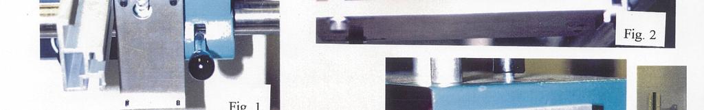
2 Guide Clip Readhead (cable not shown) Display Hinge General Display Digital Scale 2
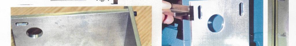
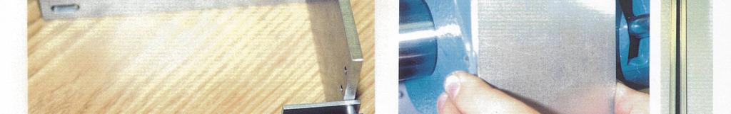
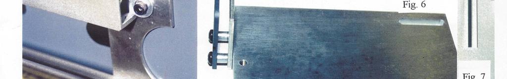
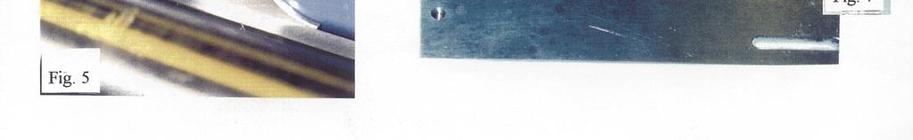
3 Getting Started: Be sure to keep the parts for the rip and crosscut kits separate if you have purchased both. The readhead has been shipped on the scale, and should remain on the scale if possible. (Damage may occur if the readhead is removed and not properly placed back on the scale.) Installation: 1. Attach the rip scale mounts to the scale using the 6-32 x 3/8 flat head screws. Refer to Figure 7 for the correct orientation. Grind the screws flush on the backside of the brackets. 2. Remove the screws holding the manual scale to the table. Slip the scale mounts between the manual scale and the table. Replace two of the screws. Mark the location for the third hole in the table extrusion. Drill a ¼ hole through the table as shown in Figure 5. Install the ¼-20 x ¾ socket head screw and flat washer to clamp the scale. 3. Assemble the guide clip spacer and guide clip protector to the clip mount plate. Refer to Figure Assemble the clip mount plate to the rip mount bracket using the x ¾ Socket head screws. Adjust the plate so it is centered in the slots. Refer to Figure Slide the readhead onto the scale if it was removed. Refer to Figure 2. Note that the cable side of the readhead is oriented down. 6. Hold the assembly close to the fence so that the guide clip engages the readhead. Mark the location of the two mounting holes. Refer to Figure 4. Be sure to mount the bracket just to the right of the rip fence-mounting surface. 7. Drill and tap two ¼-20 holes. Install the assembly with two ¼-20 x 1 ½ socket head screws, flat washers, and the ¾ spacers. 8. Carefully adjust the position of the plates to center the readhead post in the guide clip and provide the proper amount of deflection over the full travel of the fence. Refer to Figure Mount the hinge to the back of the display using the 4-40 self-tapping screws. Position the display as desired. Use the foam tape or screws to attach the hinge to the casting. Refer to Figure Connect the coil cord and coupler to the display and readhead. Route and fasten the wires so they will not snag. 11. Check the displayed numbers for correct orientation: a. if the stop is moved and larger numbers are expected on the display, but smaller numbers are shown, parameter Pr0 of the digital display needs to be changed. Refer to the ProScale Manual for more information. Calibration of the Digital Display: 1. Check that the display is in ABS mode (ABS will be showing in the upper left corner of the display). If the display is in INC, press and hold the ABS/INC key for 3 seconds. 2. Check that the display is not locked (LOCK should NOT be showing in the upper left corner). If the display is in LOCK mode, press and hold the MODE and ZERO buttons at the same time. 3. Lock the horizontal stop in place. Enter the distance of the stop from the saw blade, using the PLUS, MINUS, and ZERO keys. The display will count slowly at first, then speed up. 4. Press and hold the ON/OFF button. Press the MODE button (press and release in less than a second). Release the ON/OFF button. The keyboard is now locked. It can be unlocked by repeating this procedure. LOCK should appear in the upper left corner of the display. 5. The above calibration procedure should be repeated each time a saw blade is changed. 3
4 6. The ABS/INC key is used for setting temporary zero positions if needed. After using a temporary zero location, press and hold the ABS/INC key for 3 seconds to return to ABS (the distance to the saw blade). Troubleshooting: ProScale is accurate close to the saw blade, but not accurate at larger distances: Check the alignment of the saw fence. The alignment will affect the measurements at larger distances. Also be sure to check the mounting of all ProKit components. Any loose bolts can allow for slop measurements. ProScale resets itself while saw is running and the fence is locked: The display has been accidentally reset. Large voltage spikes from nearby motors, inverters, or dust collection systems can cause this. Be sure that all devices are properly grounded. Also, extreme vibration can cause this. Mount the display in a different location. Be sure the ABS/INC key has not been accidentally pressed. If so, press and hold for 3 seconds to return to ABS reading. ProScale resets itself while the saw is not running and the fence is locked: Be sure the ABS/INC key has not been accidentally pushed. If so, press and hold for 3 seconds to return to ABS reading. Be sure the ZERO button has not been accidentally pushed. If so, you will need to recalibrate the saw fence. Be sure to LOCK the value into the display (see page 38 in ProScale Manual). ProScale display reads ERR 2 or No Enc : Make sure the connector is fully inserted into the display. Also, be sure the readhead is on the scale. To clear the error, simply unplug the readhead for one second and re-insert the connector to the display. You will need to recalibrate. The fence has been moved too quickly (maximum speed is 430mm per second). To clear the error, simply unplug the readhead for one second and re-insert the connector to the display. You will need to recalibrate. The display reads B, BAT, or displays a battery symbol: Your batteries need to be changed. ProScale uses two standard AA alkaline cells. To change the batteries, unscrew the top cover (two screws) and remove old batteries. Be sure to avoid touching the brass battery contacts as much as possible. These are specially designed to be loose while you are changing batteries-do not attempt to bend them. My problem is not listed-where do I get help? Read through both all the manuals for answers to other commonly asked questions. Check Accurate Technology's web site for further information ( Contact Accurate Technology at Have your ProKit information ready when calling (machine model, part number, date of purchase, and point of purchase). Accurate Technology at customerservice@accurate-technology.com. 4


5 Fax Instructions #HolzHer 1243 Rip Kit, Standard Display, Rev 02/2001 5
Delta Unifence Kit Installation Instructions
 Delta Unifence Kit Installation Instructions Please note this installation kit is designed for installation on the Delta Commercial Unifence (units made between 1993 and current). Accurate Technology manufactures
Shop Fox Fence Kit Installation Instructions:
 Shop Fox Fence Kit Installation Instructions: Please note this installation kit is designed solely for installation on a Shop Fox Classic Fence. Accurate Technology manufactures kits for other saw fences
Biesemeyer Fence Kit Installation Instructions:
 Biesemeyer Fence Kit Installation Instructions: Please note this installation kit is designed solely for installation on a Biesemeyer Commercial Fence. Accurate Technology manufactures kits for other saw
Paoloni Rip Kit Installation Instructions
 Paoloni Rip Kit Installation Instructions Please note this installation kit is designed for installation only on Paoloni P150, P260, P300 Sliding Table Saws, rip fence. Accurate Technology manufactures
Delta Unifence Kit Installation Instructions
 Delta Unifence Kit Installation Instructions Please note this installation kit is designed for installation on the Delta Commercial Unifence (units made between 1993 and current). Accurate Technology manufactures
Paoloni Rip Kit Installation Instructions
 Paoloni Rip Kit Installation Instructions Please note this installation kit is designed for installation only on Paoloni P320, P30N, and P30NP Sliding Table Saws, rip fence. Accurate Technology manufactures
ProScale. Model 18W. Limited Edition. Model 18W
 ProScale Model 18W Limited Edition Model 18W WARRANTY Accurate Technology, Inc. warrants the ProScale Model 18W against defective parts and workmanship for 1 year commencing from the date of original purchase.
Analog Interface Unit Operation Manual
 Analog Interface Analog Interface Unit Operation Manual WARRANTY Accurate Technology, Inc. warrants the product against defective parts and workmanship for 1 year commencing from the date of original purchase.
Installation & Operation
 LED Readout Installation & Operation WARRANTY Accurate Technology, Inc. warrants the ProScale Systems against defective parts and workmanship for 1 year commencing from the date of original purchase. Upon
3 Input Multiplexer Operation Manual
 ProMUX-3 3 Input Multiplexer Operation Manual WARRANTY Accurate Technology, Inc. warrants the ProMUX-3 against defective parts and workmanship for 1 year commencing from the date of original purchase.
ProScale. Models 150, 250, 180, 280, 380 & 580 INSTALLATION
 ProScale Models 150, 250, 180, 280, 380 & 580 INSTALLATION WARRANTY Accurate Technology, Inc. warrants the ProScale Models 150, 180, 250, 280, 380 and 580 against defective parts and workmanship for 1
3M Add-On Terminals 4220P (100, 200, 300 & 400 pairs)
") 3M Add-On Terminals 4220P (100, 200, 300 & 400 pairs) Instructions August 2011 3 78-8130-2330-1-C 1.0 General 1.1 The 3M Add-On Terminals 4220P-100, 4220P-200, 4220P-300 and 4220P-400 are designed to expand
3M Add-On Terminals 4220P (100, 200, 300 & 400 pairs) Instructions August 2011 3 78-8130-2330-1-C 1.0 General 1.1 The 3M Add-On Terminals 4220P-100, 4220P-200, 4220P-300 and 4220P-400 are designed to expand
Section. Service & Maintenance. - Core & Hard Disk Drive (HDD) - Amplifier - Monitor - UPS - Dollar Bill Acceptor - Fan Filter G - 1
 - Amplifier - Monitor - UPS - Dollar Bill Acceptor - Fan Filter G - 1") Section G Service & Maintenance - Core & Hard Disk Drive (HDD) - Amplifier - Monitor - UPS - Dollar Bill Acceptor - Fan Filter G - 1 Core Removal Core & HDD 1. Open the door. 2. Perform shutdown procedure.
Section G Service & Maintenance - Core & Hard Disk Drive (HDD) - Amplifier - Monitor - UPS - Dollar Bill Acceptor - Fan Filter G - 1 Core Removal Core & HDD 1. Open the door. 2. Perform shutdown procedure.
Adapter Kit for PanelView 1200/1200e Touch Screen Terminal Cutout
 Installation Instructions Adapter Kit for PanelView 1200/1200e Touch Screen Terminal Cutout Catalog Numbers 2711-NR5T, 2711P-RAT12E2 Topic Page About This Publication 1 Important User Information 2 About
DI-ACRO #24 HAND SHEAR INSTRUCTION MANUAL
 DI-ACRO #24 HAND SHEAR INSTRUCTION MANUAL REV. G 6/12 1 TABLE OF CONTENTS A. SAFETY INFORMATION PG. 3 B. SET UP PROCEDURE PG. 3 C. MAINTENANCE PG. 3 D. TECHNICAL DATA PG. 3 E. OPERATING PROCEDURES PG.
P F
 12430 55 TH ST N OAK PARK HEIGHTS, MN 55082 P 651-342-1756 F 651-342-1293 INFO@DIACRO.COM Copyright 2014 REV. 9-MAY-2014 1 SAFETY INFORMATION PG. 3 SET-UP PROCEDURE PG. 3 MAINTENANCE PG. 3 TECHNICAL DATA
TH ST N OAK PARK HEIGHTS, MN P F
 12430 55 TH ST N OAK PARK HEIGHTS, MN 55082 P 651-342-1756 F 651-342-1293 INFO@DIACRO.COM SAFETY INFORMATION PG. 3 SET UP PROCEDURE PG. 3 MAINTENANCE PG. 3 TECHNICAL DATA PG. 3 OPERATING PROCEDURES PG.
INSTALLATION INSTRUCTIONS
 INSTALLATION INSTRUCTIONS 19 20 21 01 07 22 23 13 10 12 08 17 18 11 02 14 15 04 03 16 WELCOME PARTS LIST Thank you for purchasing this HealthPoint Technology Cabinet from Humanscale! Before you begin installing
PREFACE. Thank you for choosing Zen Space Desks. We hope your desk helps you find your zen when being used. Zen Space Desks Team
 INSTRUCTION MANUAL PREFACE We are thrilled that you have chosen Zen Space. Congratulations, you have selected one of the most advanced and sophisticated Power Adjustable Workstations available today. Our
Model 1100B CHG Terminator. Operating Instructions
 Model 1100B CHG Terminator Operating Instructions 1 Contents: 1.0 Safety Information... 3 2.0 General Introduction... 3 3.0 Operation... 4 2.8 2.1 2.7 V 2.2 2.9 2.2 2.10 2.11 2.11 2.3 2.4 2.5 2.5 2.6 2
General Instruction Manual Includes: ProScale Model 150 & 250
 ProScale General Instruction Manual Includes: ProScale Model 150 & 250 ProStop Measurement Table Kits ProPanel ProCaliper Digital Displays Accurate Technology, Inc. 270 Rutledge Rd. Unit E Fletcher, NC
Universal Desktop and Monitor Stand
 Universal Desktop and Monitor Stand Installation Instructions Kit P/N: 114-6013 Kit Contents Kit Contents: (1) Stand Assembly (1) VESA Monitor Bracket (1) Bottom Bracket (1) Top Bracket (1) Clamp Bracket
ENC 125 T/E REFERENCE MANUAL. Acu-Rite Companies Inc.
 ENC 125 T/E REFERENCE MANUAL Acu-Rite Companies Inc. ENC 125 T/E Page Introduction... 2 Mounting Preparation... 3 Mounting Information... 4 Encoder Dimensions - ENC 125 T (top mount)... 5 Encoder Dimensions
3M DSLAM Mounting Bracket Kit J0746
 3M DSLAM Mounting Bracket Kit J0746 Instructions July 2009 3 Contents 1.0 3M DSLAM Mounting Bracket J0746 - Installation...3 2.0 DSLAM Installation, Nokia...5 3.0 Accessory Kit, Cable Addition Shroud J0747
AMERICA S PREMIER EXERCISE EQUIPMENT RCD-347. Chin-Dip / Ab-Back / Push-Up Stand. TuffStuff Fitness Equipment, Inc. 83 3/4" 43 1/4" 44 3/4"
 ASSEMBLY INSTRUCTIONS 83 3/4" RCD-347 44 3/4" 43 1/4" Chin-Dip / Ab-Back / Push-Up Stand TuffStuff Fitness Equipment, Inc. 1325 E. Franklin Avenue Pomona, CA 91766, USA Ph: 909-629-1600 Fax: 909-629-4967
36'' & 48'' E-Z Shutter Fan Installation & Operator s Instruction Manual
 6'' & 8'' E-Z Shutter Fan Installation & Operator s Instruction Manual MV-8B 8/99 August 999 MVB Chore-Time Warranty 6'' 8'' EZ Shutter Fans Chore-Time Warranty Chore-Time Equipment warrants each new product
7" Touch Screen Display
 7" Touch Screen Display Installation Guide Contents Minimum Requirements...1 Select a Location...1 Initial Setup...2 Unboxing...2 Installation...3 Prepare the Panel...3 Install the Mounting Plate...3 Mount
INSTALLATION INSTRUCTIONS
 INSTALLATION INSTRUCTIONS 3YEAR WARRANTY & LIMITATION OF LIABILITY TRI-TRONICS COMPANY, INC. warrants that the products delivered by it will be of the kind and quality described in the order or contract
3M Cross-Connect Cabinet Riser Installation Guide
 3M Cross-Connect Cabinet Riser Installation Guide Installing riser in stake, hand hole and pad-mount applications Instructions October 2016 78-0015-3063-9-B 2 October 2016 78-0015-3063-9-B Contents 1.
To connect the AC adapter:
 Replacing the AC Adapter Replacing the AC Adapter 3 Plug the power cord into a wall outlet. The power indicator turns on. To connect the AC adapter: Connect the power cord to the AC adapter. Power indicator
Version Accurate Technology, Inc.
 Single Axis Position Control Unit (PCU) User s Manual Version 2.040 270 Rutledge Rd. Suite E Fletcher, North Carolina 28732 USA 828-654-7920 www.proscale.com The contents of this document are protected
IBM. Rack Installation Instructions
 IBM Rack Installation Instructions Review the documentation that comes with your rack cabinet for safety and cabling information. When installing your server in a rack cabinet, consider the following:
Flex Pro Series Assembly Guide
 ELECTRIC HEIGHT-ADJUSTED SIT TO STAND DESK Table of Contents CAUTION, USE & LIABILITY... 2 PARTS & HARDWARE LIST... 3 PARTS / COMPONENT DIAGRAMS... 3 ASSEMBLY INSTRUCTIONS... 5 BLUETOOTH... 10 TROUBLESHOOTING...
ProScale Series : 404, 405, 406, 407 Systems. User Manual for. with DRO Firmware V2.0 and Higher
 ProScale Series 950 User Manual for 950-: 404, 405, 406, 407 Systems with DRO Firmware V2.0 and Higher Warranty Mitutoyo America Corporation Inc., (MAC) warrants this product against defective parts and
Universal Tablet Mount Accessory for Flex TechBridge
 Assembly Instructions Universal Tablet Mount Accessory for Flex TechBridge Universal Tablet Mount Accessory Universal Tablet Mount Accessory mounted on Flex Arm CONTENTS Important User Information...........................2
CUBE Micro Station User Guide
 CUBE Micro Station User Guide Models TVS10AC CUBE Micro Station - User Guide 1 of 23 How To Use This Guide This User Guide is a resource to provide you guidelines and best practices as you begin using
Installation Guide. Retrofit Kit for USB Ready Intraoral Systems
 Installation Guide Retrofit Kit for USB Ready Intraoral Systems Table of Contents Wall-Mount Retrofit Kit... 2 Introduction... 2 Connecting the Articulating and Horizontal Arm Cables... 2 Installing the
USER MANUAL TEMPLATE ELECTRONIC DEADBOLT LOCK
 Mark Ø1" (25.4mm) hole at center of door edge. 2" 1-3/4" 1-9/16" 1-3/8" 51 45 40 35 Fit here on door edge FOR BACKSET 70mm (2-3/4 ) FOR BACKSET 60mm (2-3/8 ) TEMPLATE Limited Warranty Statements 1. Warranty
90130, 90131, POP DISPLAY ASSEMBLY INSTRUCTIONS
 90130, 90131, 90132 POP DISPLAY ASSEMBLY INSTRUCTIONS WARNING! Ensure ALL hardware is securely fastened using appropriate tools to prevent damage to the display unit, the products or any injury due to
Replacing the PanelMate Power Pro 1785 Series, PanelMate epro 7585x-8 and 7685x-8 Series Backlight Assembly
 Replacing the PanelMate Power Pro 1785 Series, PanelMate epro 7585x-8 and 7685x-8 Series Assembly Introduction The Replacement Kit provides a replacement backlight for the PanelMate Power Pro 1785 Series,
ProScale LCD Readout Quick Start Guide
 ProScale LCD Readout Quick Start Guide This Guide includes basic operation instructions for 950, General Purpose, Basic & In-Panel LCD Readouts For the Complete OPERATION Manual go to www.proscale.com/manuals.htm
Packard Bell. EasyNote BG Series. Disassembly Guide
 Packard Bell EasyNote BG Series Disassembly Guide Table of Contents Overview...3 Technician Notes...3 Disassembly Instructions...3 Reassembly Instructions...3 Required Tools...3 Battery...4 Hard Disk...4
User Manual for Models
 ProScale 950 Series User Manual for Models 950-404, 950-405, 950-406, 950-407 with DRO Firmware V2.0 or higher WARRANTY Accurate Technology, (ATI) warrants this product against defective parts and workmanship
HeadMouse Extreme. Bracket Installation Instructions for DynaVox Maestro. Additional Resources. Bracket Installation Instructions for Maestro
 Additional Resources HeadMouse Extreme User Guide o Included in the HeadMouse Extreme package o And, available online at www.orin.com Extra and/or replacement targets can be purchased online at: http://shop.orin.com
Rack Installation Instructions
 Rack Installation Instructions Review the documentation that comes with your rack cabinet for safety and cabling information. When installing your server in a rack cabinet, consider the following: v Two
Turbo Fiberglass Cone Fan and Grill Fan 36 Direct Drive. Installation & Operator s Instruction Manual
 Turbo Fiberglass Cone Fan and Grill Fan 36 Direct Drive Installation & Operator s Instruction Manual July 1998 MV1384B Chore-Time TURBO TM Fan Extended Warranty Chore-Time Equipment warrants new TURBO
Fantasea Blue Ray Tray (Cat. No. 2040, 2045, 2050) Instruction Manual
 Instruction Manual") Fantasea Blue Ray Tray (Cat. No. 2040, 2045, 2050) Instruction Manual For Illustration- Blue Ray Double Tray with Housing 1 The Fantasea Blue Ray Tray allows integrating different components in an underwater
Fantasea Blue Ray Tray (Cat. No. 2040, 2045, 2050) Instruction Manual For Illustration- Blue Ray Double Tray with Housing 1 The Fantasea Blue Ray Tray allows integrating different components in an underwater
Z-Truck (Vertical Moving) Z-truck Flag. Y-Truck (Horizontal Moving) FIGURE 1: VIEW OF THE Z-TRUCK. Flexshaft Assembly
 Z-truck Flag. Y-Truck (Horizontal Moving) FIGURE 1: VIEW OF THE Z-TRUCK. Flexshaft Assembly") Replacing the LCD Cable To remove and replace the LCD Cable you will need the following tools: #2 Phillips screwdriver (magnetic tip preferred) Socket wrench with 10mm socket Removing the Side Panel 1.
Replacing the LCD Cable To remove and replace the LCD Cable you will need the following tools: #2 Phillips screwdriver (magnetic tip preferred) Socket wrench with 10mm socket Removing the Side Panel 1.
Instruction Manual. Balanced Audio Upgrade Installation. iport IW-21/IW-22 Upgrade Kits. Balanced Audio Upgrade Kit. (iport IW-21)
") Introduction The iport IW Balanced Audio, Balanced Video, and RS-232 Upgrade Kits add functionality and capability to iport IW-21 and IW-22 models. Balanced Audio Upgrade Kit For use with iport IW-21 models.
Introduction The iport IW Balanced Audio, Balanced Video, and RS-232 Upgrade Kits add functionality and capability to iport IW-21 and IW-22 models. Balanced Audio Upgrade Kit For use with iport IW-21 models.
ATTENTION: OBSERVE PRECAUTIONS FOR HANDLING ESD-SENSITIVE DEVICES
 15 Monitor Removal 1. Turn off and unplug the game. 2. Place something in front of the game to brace the bezel once the strain relief cord is undone, then unlock and open the CPU section. 3. Remove the
TABLE OF CONTENTS SECTION 1 TABLETOP CONFIGURATION SECTION 2 TABLETOP CONFIGURATION ACCESSORIES SECTION 3 SLIDE CONFIGURATION
 S6 USER S MANUAL TABLE OF CONTENTS SECTION 1 TABLETOP CONFIGURATION SECTION 2 TABLETOP CONFIGURATION ACCESSORIES SECTION 3 SLIDE CONFIGURATION SECTION 4 SLIDE CONFIGURATION ACCESSORIES SECTION 5 RACK MOUNT
Vortex Series 2-leg Desk Assembly Guide
 ELECTRIC HEIGHT-ADJUSTED SIT TO STAND DESK Vortex Series 2-leg Desk Assembly Guide For desk with underframe Model No. AL4628-XX REV-1509A Table of Contents IMPORTANT SAFETY INSTRUCTIONS... 3 CAUTION, USE
Packard Bell. EasyNote BU Series. Disassembly Guide
 Packard Bell EasyNote BU Series Disassembly Guide Table of Contents Overview...3 Technician Notes...3 Disassembly Instructions...3 Reassembly Instructions...3 Required Tools...3 Battery...4 Memory...4
SAVE THESE INSTRUCTIONS
 and Height Mounts Assembly, Installation and Operating Instructions Model Nos. QL, QLA, ARM250, QLM6 and QLAM6 NOTE: Check all parts for shipping damage. In case of shipping damage, DO NOT use. Contact
PRO Owner's Manual
 PRO 3600 Owner's Manual Feature Overview The Pro 3600 operates normally in a standard reference mode where level is displayed as 0.00. However, a new reference point for 0.00 can easily be established
PRO 360. Owner's Manual
 PRO 360 Owner's Manual Introduction The Pro 360 Digital Protractor is a revolutionary measuring tool that provides an immediate, digital reading of all angles in a 360 circle. The machined aluminum frame
Flat Panel Static Wall Mount MSP-SS (GSM-210)
") INSTALLATION INSTRUCTIONS Flat Panel Static Wall Mount (GSM-2) The static wall mount fits most 23 to 30 displays. The mount was designed to adapt to the VESA 75mm/0mm, 0mm/0mm, and 200mm/0mm compliant
INSTALLATION INSTRUCTIONS Flat Panel Static Wall Mount (GSM-2) The static wall mount fits most 23 to 30 displays. The mount was designed to adapt to the VESA 75mm/0mm, 0mm/0mm, and 200mm/0mm compliant
Allen-Bradley Drives. Instructions. (For 6180 Industrial Computers)
") Instructions (For 6180 Industrial Computers) This document describes how to remove or install a Pentium processor in the 6180 Industrial Computer. Processor specifications are also provided. The processor
Instructions (For 6180 Industrial Computers) This document describes how to remove or install a Pentium processor in the 6180 Industrial Computer. Processor specifications are also provided. The processor
OWNER S MANUAL AMERICA S PREMIER EXERCISE EQUIPMENT RLM-855WS. Lat Machine W/200 Lbs Steel Weight Stack 83 1/2" 64 3/4" 45 1/4"
 OWNER S MANUAL 83 1/2" RLM-8WS 4 1/4" 64 3/4" Lat Machine W/200 Lbs Steel Weight Stack AMERICA S PREMIER EXERCISE EQUIPMENT RLM-8WS Rev0 Revision Date -30-2007 Introduction About the Lat Machine W/200
i-series Videoconference Fixture
 TM i-series Videoconference Fixture Operating Instructions 580 Mayer Street, Building #7, Bridgeville, PA 15017 phone 412.206.0106 fax 412.206.0146 www.brightlines.com 2013 Brightline, L.P. Safety To prevent
Keypad Lock. Operation and Service Manual. Order parts online
 Keypad Lock Order parts online www.follettice.com Operation and Service Manual 801 Church Lane Easton, PA 18040, USA Toll free (800) 523-9361 (610) 252-7301 Fax (610) 250-0696 www.follettice.com 00163345R00
Pit Transition with 24" Fan Installation and Operators Instruction Manual
 Pit Transition with 4" Fan Installation and Operators Instruction Manual z Fan and Fan Framing Dimensions Shutter Fan " [8. cm] 6" [9.4 cm] 6-/4" [9. cm] Cone Fan " [5. cm] 4-/6" [88.4 cm] 75-/" [9.8 cm]
MPP200 User s Manual
 2011 Visionary Solutions, Inc. All rights reserved. Please visit the support section of our website at www.vsicam.com for manuals, other documentation, and software downloads. Visionary Solutions, Inc.
9.5 Dual-Sided Wall Mount LED Lighted Mirror, 1x/10x
 9.5 Dual-Sided Wall Mount LED Lighted Mirror, 1x/10x MLW45 Series Before using please read the instruction manual and keep it for future use. WALL MOUNT VANITY MIRROR Ovente mirrors are equipped with energy-saving
EconoComp Product. 6th Edition S I G N E X T R U S I O N S A N D K I T S EFFECTIVE APRIL 1, 2018
 S I G N E X T R U S I O N S A N D K I T S TM EconoComp Product EFFECTIVE APRIL 1, 8 th Edition E C O N O C O M P E X T R U S I O N S Sign Cabinet Kits General Information Included in Kit Pricing The filler
Plus 4 Additional Controller To be used in conjunction with Genus III or Genus IV
 Additional Controller To be used in conjunction with Genus III or Genus IV INSTALLATION & OPERATING INSTRUCTIONS AstralPool Australia Pty. Limited. A.B.N. 97 007 284 504 Melbourne: Ph: (03) 8796 8600 Fax:
WEASEL N/B MAINTENANCE
 2. System Assembly & Disassembly 2.1 System View 2.1.1 Front View ❶ Microphone Connector ❷ Audio Input Connector ❸ Audio Output Connector ❹ Top Cover Latch ❹ ❶ ❸ ❷ 2.1.2 Left-Side View ❶ VGA Port ❷ S-Video
Indoor Protected Entrance Terminal 4588 Series
 Indoor Protected Entrance Terminal 4588 Series Instructions Underwriters Laboratories (UL) Listed September 2003 78-8135-1209-8-A 1.0 General The 3M Indoor Protected Entrance Terminal (PET) 4588 Series
INSTRUCTION MANUAL. SGB20(D) Transient Protection System. June Copyright 2008 Campbell Scientific (Canada)Corp.
 Transient Protection System. June Copyright 2008 Campbell Scientific (Canada)Corp.") INSTRUCTION MANUAL SGB20(D) Transient Protection System June 2008 Copyright 2008 Campbell Scientific (Canada)Corp. WARRANTY AND ASSISTANCE This equipment is warranted by CAMPBELL SCIENTIFIC (CANADA) CORP.
INSTRUCTION MANUAL SGB20(D) Transient Protection System June 2008 Copyright 2008 Campbell Scientific (Canada)Corp. WARRANTY AND ASSISTANCE This equipment is warranted by CAMPBELL SCIENTIFIC (CANADA) CORP.
Extra Large Full Motion TV Mount for Televisions
 8008981 TV Size Range: 47 ~ 84 Maximum Weight Capacity: 60 kg/132 lbs Maximum Mounting Pattern: 800 mm x 600 mm (31.4 x 23.6 ) Distance to the Wall: 5.5-45 cm Extra Large Full Motion TV Mount for 47-84
Dell Inspiron N5110 Service Manual
 Dell Inspiron N5110 Service Manual Regulatory model: P17F Regulatory type: P17F001 Notes, Cautions, and Warnings NOTE: A NOTE indicates important information that helps you make better use of your computer.
Lotus DX. sit-stand workstation. assembly and operation instructions. MODEL # s: LOTUS-DX-BLK LOTUS-DX-WHT
 Lotus DX assembly and operation instructions sit-stand workstation MODEL # s: LOTUS-DX-BLK LOTUS-DX-WHT safety warnings 13.6 Kg 30 lbs. 2.2 Kg 5 lbs. safety instructions/warning Read and follow all instructions
SpeedVault Model SV 500 User Manual
 SpeedVault Model SV 500 User Manual Patented Rev 1 (10/11) Firearm Safety WARNING: The SpeedVault safe or any other firearm storage device cannot take the place of other safety procedures including advising
QuickTouch (QT4) Owner s Manual
 Owner s Manual") QuickTouch (QT4) Owner s Manual 4-Function Hand-Held Wireless Remote Control IMPORTANT SAFETY INSTRUCTIONS READ AND FOLLOW ALL INSTRUCTIONS SAVE THESE INSTRUCTIONS Table of Contents SECTION I. APPLICATION...
QuickTouch (QT4) Owner s Manual 4-Function Hand-Held Wireless Remote Control IMPORTANT SAFETY INSTRUCTIONS READ AND FOLLOW ALL INSTRUCTIONS SAVE THESE INSTRUCTIONS Table of Contents SECTION I. APPLICATION...
Replacement Keyswitch Assembly
 Installation Instructions Replacement Keyswitch Assembly (Catalog No. 2711E-NKSW1) Applicable Terminals Use this replacement keyswitch with PanelView Terminals 2711-KA1, -KC1, -TA1, -TC1, -TA4, -TC4 and
Hardware Replacement Guide
 Hardware Replacement Guide Types 6491, 8013, 8702, 8706 Types 8716, 8970, 8972, 8976 Types 8980, 8982, 8986, 8992 Types 8994, 9266, 9276, 9278 Types 9282, 9286, 9288, 9374 Types 9378, 9380, 9384, 9628
EVOLVE1-M MONITOR ARM
 EVOLVE1-M MONITOR ARM EVOLVE1-M Rev A 2/17 Model EVOLVE1-M-SLV Model EVOLVE1-M-BLK Model EVOLVE1-M-WHT ASSEMBLY AND ADJUSTMENT EVOLVE1-M MONITOR ARM PARTS AND TOOLS PLEASE REVIEW these instructions before
DataPort 350 & 525 USB 2.0 and FireWire Enclosure User s Guide (800)
") DataPort 350 & 525 USB 2.0 and FireWire Enclosure User s Guide WWW.CRUINC.COM (800) 260-9800 TABLE OF CONTENTS PAGE Package Contents 1 Features and Requirements 2 Installation 6 Trouble Shooting 16 Technical
DataPort 350 & 525 USB 2.0 and FireWire Enclosure User s Guide WWW.CRUINC.COM (800) 260-9800 TABLE OF CONTENTS PAGE Package Contents 1 Features and Requirements 2 Installation 6 Trouble Shooting 16 Technical
Keysight Add Source and Receiver Attenuators Upgrade Kit
 Keysight Add Source and Receiver Attenuators Upgrade Kit To Upgrade PNA N5221A or N5222A Option 401 to Option 417 Upgrade Kit Order Numbers: N5221AU-417 or N5222AU-417 Keysight Kit Number: N5222-60107
INSTALLATION MANUAL DATAVAULT DATAVAULT - BARE JOBSITE STORAGE SOLUTIONS
 JOBSITE STORAGE SOLUTIONS ALWAYS ON THE JOB INSTALLATION MANUAL 118-01 DATAVAULT 118-02 DATAVAULT - BARE Werner Co. 724-588-2000 93 Werner Rd. 888-523-3371 toll free/ llamada gratuita Greenville, PA 16125
Packard Bell Vibe 300 Disassembly Manual
 Packard Bell Vibe 300 Disassembly Manual 1 Table of Contents Overview 2 Technician Notes 2 Disassembly Instructions 2 Reassembly Instructions 2 Required Tools 2 Removing the Bottom Cover 3 Removing the
Narc Box Owners Manual & Warranty Information
 Narc Box Owners Manual & Warranty Information 800-445-3640 Brandon@NarcBox.com General Description The Narc Box is a portable narcotic security system designed to keep controlled substances locked and
LINE VOLTAGE TESTER CT101 USER S MANUAL. Please read this manual carefully and thoroughly before using this product.
 LINE VOLTAGE TESTER USER S MANUAL CT101 Please read this manual carefully and thoroughly before using this product. KEY FEATURES Visual indication of AC or DC voltage Easy to use approved Safe for CAT
PRO 360. Owner's Manual
 One-Year Limited Warranty If, within one year from the date of original purchase, the Pro 360 Digital Protractor fails to function because of defects in materials or workmanship, the manufacturer will,
Monitor Mount with Articulating Arm and Laptop Riser
 Monitor Mount with Articulating Arm and Laptop Riser ARMUNONB *actual product may vary from photos FR: Guide de l utilisateur - fr.startech.com DE: Bedienungsanleitung - de.startech.com ES: Guía del usuario
Dell XPS 14z Owner s Manual
 Dell XPS 14z Owner s Manual Computer model: L412z Regulatory model: P24G series Regulatory type: P24G001 Notes, Cautions, and Warnings NOTE: A NOTE indicates important information that helps you make better
TB-100 ControLynx Terminal Block
 TB-100 ControLynx Terminal Block TECHNICAL MANUAL Version 1.3 September 2006 Copyright This technical manual and the equipment, firmware and software described herein are copyrighted by INTENT DIGITAL
INSTALLATION MANUAL DATAVAULT DATAVAULT - BARE JOBSITE STORAGE SOLUTIONS
 JOBSITE STORAGE SOLUTIONS ALWAYS ON THE JOB INSTALLATION MANUAL 118-01 DATAVAULT 118-02 DATAVAULT - BARE Werner Co. 724-588-2000 93 Werner Rd. 888-523-3371 toll free/ llamada gratuita Greenville, PA 16125
Parts List: Assembly Instructions:
 My Ride SERVICE MANUAl MyRide ASSEMBLY GUIDE 1.1 ASSEMBLY INSTRUCTIONS ASSEMBLING THE MYRIDE Parts List: Heavy Plate Stabilizer Fin - Right Stabilizer Fin - Left Stabilizer Fin - Large Middle Power Cord
Removing and Replacing Parts
 Removing and Replacing Parts Preparing to Work Inside the Computer Recommended Tools Screw Identification System Components Hard Drive Fixed Optical Drive Media Bay Devices Memory Modules Mini PCI Card
Proliphix EPA-60 Installation Guide
 Proliphix EPA-60 Installation Guide Rev 1.2 Page 2 of 5 Installation CAUTION THE EPA-60 SHOULD ONLY BE POWERED WITH THE PROLIPHIX POWER SUPPLY INCLUDED WITH THE EPA-60. DO NOT POWER THE EPA-60 WITH ANY
TCD600 OPEN LOOP TENSION CONTROLLER INSTALLATION, OPERATION MANUAL ADDENDUM (NETWORK FEATURE)
") TCD600 OPEN LOOP TENSION CONTROLLER INSTALLATION, OPERATION MANUAL ADDENDUM (NETWORK FEATURE) INTRODUCTION Nexen s TCD600 is a LonWorks compatible controller. It has a unique networking feature which enables
TCD600 OPEN LOOP TENSION CONTROLLER INSTALLATION, OPERATION MANUAL ADDENDUM (NETWORK FEATURE) INTRODUCTION Nexen s TCD600 is a LonWorks compatible controller. It has a unique networking feature which enables
TABLE OF CONTENTS. 9.0 Warranty
 9.0 Warranty ELECTROMATIC Equipment Co., Inc. (ELECTROMATIC) warrants to the original purchaser that this product is of merchantable quality and confirms in kind and quality with the descriptions and specifications
Instructions for installing your QuiltCam on your Gammill quilt machine.
 Instructions for installing your QuiltCam on your Gammill quilt machine. The items include with your QuiltCam Items included in all packages: QuiltCam Control Box, See Figure 1 Power Supply, Figure 2 Video
R52 Top Commander. Installation and Configuration Guide. 325 Sharon Park Dr. #652. Menlo Park, CA USA (650)
") R52 Top Commander Installation and Configuration Guide 325 Sharon Park Dr. #652 Menlo Park, CA 94025 USA (650) 241-1161 www.fes-auto.com R52 Top Commander Installation Guide Page 2 Table of Contents Chapter
R52 Top Commander Installation and Configuration Guide 325 Sharon Park Dr. #652 Menlo Park, CA 94025 USA (650) 241-1161 www.fes-auto.com R52 Top Commander Installation Guide Page 2 Table of Contents Chapter
Blackout Shutter Kits with Breathable Wall Light Traps
 Blackout Shutter Kits with Breathable Wall Light Traps 2018 Growers Supply All Rights Reserved. Reproduction is prohibited without permission. Revision date: 05.10.18 Maintain controlled airflow without
Service & Maintenance
 Service & Maintenance Internal Amplifier External (Peavey) Amplifier Core & HDD Monitor UPS Dollar Bill Acceptor Coin Mechanism Cleaning Fans & Filter G1-1 Internal Amplifier Amplifier Removal 1. Disconnect
212iL Rev. 1.1
 212iL 1 International Electronics, Inc. 427 Turnpike Street Canton, Massachusetts 02021 212iL (illuminated Luxury) Keypad Single Unit Keypad- Control Installation Manual Features: 120 User Capability Illuminated
PracticeWire Installation Manual
 PracticeWire Installation Manual Version 5.0 August 28 th, 2013 PCM Help Desk 1-877-233-9114 Page 1 Table of Contents System Overview 3 Tool List 4 Installation Guide Site Notification 5 Install Universal
Quad Monitor Desk Stand - 13" to 24" Installation Instructions
 Quad Monitor Desk Stand - 13" to 24" Installation Instructions 04-0885A 1 Unpacking Carefully remove the contents and lay out on cardboard or other protective surface Check package contents against the