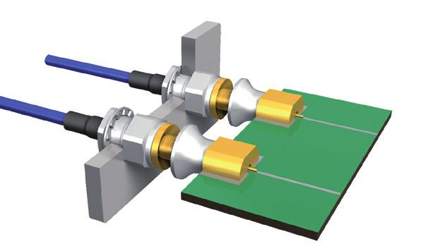
Board-to-Board connections
|
|
|
- Spencer Mosley
- 5 years ago
- Views:
Transcription

1 Board-to-Board connections MBX/MFBX/MMBX connectors Edition 2014/08
2 Innovative connections

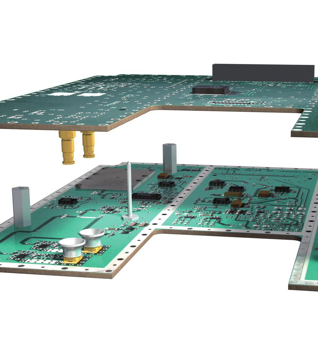
3 Your partner for system solutions The HUBER+SUHNER Group is a leading global supplier of components and systems for electrical and optical connectivity. Our customers in Communications, Industrial and Transportation markets appreciate that we are specialists with detailed knowledge of practical applications. We offer technical expertise in radio frequency technology, fiber optics and lowfrequency under one roof, thus providing a unique basis for continual innovation focused on the needs of our customers all over the world. are especially developed for board-to-board and board-tomodule RF inter-connections. The mechanical design is outstanding, allowing the MMBX and MBX to cope with mechanical misalignment in radial and axial directions and still hold an excellent electrical performance. These series are the answer to higher integration and miniaturisation. They are the perfect solution for multiple connections from board-toboard and complex stack-ups in radio module applications. The MMBX and MBX series offers a wide range of connectors for various applications.
 do not only save costs compared to cable connections but rather allow larger tolerances on all other parts.")
4 Benefits 4 Lower cost Direct board-to-board connections with compensating misalignment (axial float ± 1.2 mm) do not only save costs compared to cable connections but rather allow larger tolerances on all other parts. High output power and excellent RF performance HUBER+SUHNER board-to-board connectors can handle very high power requirements (260 W) in a module environment where high ambient temperatures are given. Minituarization HUBER+SUHNER board-to-board connectors provide the smallest board-to-board distance (6.7 mm) in class. This enables smaller designs with less weight and provide much more space on the PCB boards This opens new possibilities for module designs without active cooling. Thanks to the unique ball joint design the connectors provide excellent return loss values over the complete floating range combined with outstanding RF shielding performance. Reliable connection Due to the unique fully automated production process and therewith 100 % interface control highest quality requirements, capacity and flexibility can be achieved. Secure Mating Thanks to the largest connecting range in class and therewith always given blind mateability, very fast module assemblies are possible.


 ± 1.2 mm ± 0.8 mm ± 0.")
 ± 0.8 mm ± 0.4 mm (at 6.")
 Min.")

5 One product family covering all board-to-board applications MBX MBX 2 nd generation Very high axial float best in class High output power Excellent return loss values Smallest board-to-board distances in class Very high axial float best in class Excellent return loss values Smallest board-to-board distances in class MFBX MMBX Medium float Low cost Very good board-to-board shielding Small board-to-board distances Very high frequencies best in class Very good return loss values Smallest board-to-board distances in class Characteristics MBX and MBX 2nd MFBX MMBX Frequency DC... 6 GHz DC GHz DC GHz Axial float (misalignment) ± 1.2 mm ± 0.8 mm ± 0.3 mm Radial float (misalignment) ± 0.6 mm (at 13 mm board-to-board distance) ± 0.8 mm ± 0.4 mm (at 6.7 mm board-to-board distance) ± 1.0 mm ( 18 mm board-to-board distance) Min. board-to-board distance 13 mm 13 mm 6.7 mm Min. panel-to-board distance Min. panel-to-panel distance Power at room temperature, at 2.4 GHz <13 mm depending on connector <13 mm depending on connector typical 260 W (MBX) typical 240 W (MBX 2nd ) <13 mm depending on connector <13 mm depending on connector typical 130 W 4.63 mm 2.56 mm typical 260 W 5

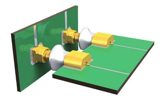
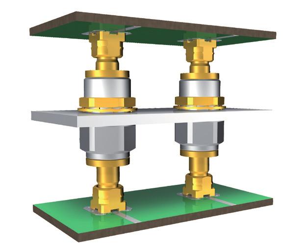

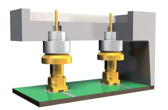

6 Applications Board-to-Board connection Panel-to-Panel connection Board-to-Board connection right angle Board-to-Board through a panel Board-to-Panel connection (filter) Board-to-Panel connection right angle 6
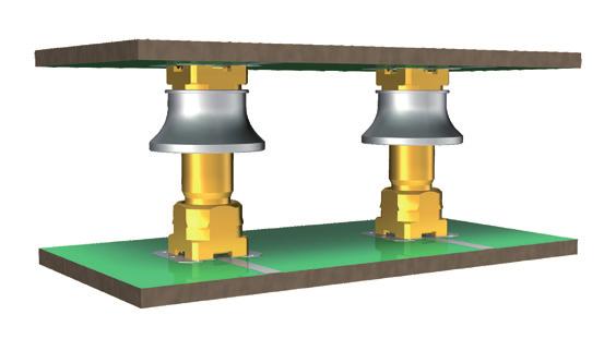
7 Series MBX design guideline Working range (axial and radial) In mated condition, the two PCB connector have to be aligned within the dimension given for the axial and radial working range. The axial working range is ± 1.2 mm, the radial working range is ± 1.0 mm. In contradiction to the MMBX interface, the tilt of the adaptor is limited with MBX. The great advantage of this feature is that there is a constant connecting range/radial working range for all adaptor lengths and thus the same funnel (pull-in range) can be used. Connecting range The two PCB connector have to be aligned within the dimension given for connecting range. The connecting range is ± 1.0 mm and is equivalent to the max. allowed misalignment between two PCB boards when mating. Recommendation HUBER+SUHNER recommends using guiding pins to align the boards within the connecting range and working range. Distance holders to maintain the axial misalignment within working range are also of benefit. HUBER+SUHNER provides outline drawings for every application with the relevant mechanical dimensions that need to be considered when designing-in MBX. 3D STEP files are available on MBX 2 nd generation An alternative, cost effective and reliable solution are the 2 nd generation MBX connectors. By keeping best in class mechanical characteristics like working and connecting range these connectors are designed to meet today s requirements within the communication industry. Standard MBX and 2 nd generation MBX are intermateable. In order to guarantee a blind mateable connection, the tilted adaptor will be guided by the funnel of the opposite connector. Connecting range Working range 7
8 Series MBX technical data MBX PCB connectors board-to-board / adaptors within series Electrical data MBX MBX 2 nd Impedance Frequency range Dielectric withstanding voltage (at sea level) Working voltage (at sea level) Insulation resistance Contact resistance - centre contact - outer contact Return loss / VSWR 5 mω 2.5 mω 50 Ω DC... 6 GHz 1 kv rms, 50 Hz 330 V rms, 50 Hz 1 GΩ 5 mω 5 mω typical values for a board-to-board connection (measured on a board) axial misalignment DC 2.5 GHz GHz 4 6 GHz ± 1.2 mm ± 0.8 mm ± 0.4 mm 22 db / db / db / db / db / db / 1.20 RF-leakage (interface only) 70 db (DC... 6 GHz) Power (room temperature) typical 260 W at 2.4 GHz typical 240 W at 2.4 GHz 15 db / db / db / 1.29 Mechanical data MBX MBX 2 nd Engagement force (slide-side) 15 N / 3.4 lbs Disengagement force (slide-side) 15 N / 3.4 lbs Durability (matings) Axial float (misalignment) ± 1.2 mm Radial float (misalignment) depending on the adaptor ± 0.6 mm (at 13 mm board-to-board distance) ± 1.0 mm ( 18 mm board-to-board distance) Environmental data MBX MBX 2 nd Temperature range 55 to +155 C / 67 to +311 F Climatic category 55 / 155 / 10 Thermal shock MIL-STD-202, method 107 G, condition B1 Moisture resistance MIL-STD-202, method 106 F Vibration MIL-STD-202, method 204 D, condition A Mechanical shock MIL-STD-202, method 213 B, condition B Corrosion MIL-STD-202, method 101, condition B Processing data MBX MBX 2 nd Adherent to the print - shearing - pulling (vertical to PCB) 150 N / 33.7 lbs 150 N / 33.7 lbs Material data Connector parts Material Plating Centre contact brass / bronze / copper-beryllium alloy SUCOPRO gold plating Outer contact brass / bronze SUCOPRO gold plating / SUCOPLATE Body brass SUCOPRO gold plating / SUCOPLATE Insulators LCP / PTFE / PFA Funnel Brass / PA SUCOPLATE / 8
9 Series MBX technical data MBX cable connectors Electrical data Impedance Frequency range Dielectric withstanding voltage (at sea level) Working voltage (at sea level) Insulation resistance Contact resistance - centre contact - outer contact Return loss / VSWR (typical values) Requirements 50 Ω DC... 6 GHz 750 V rms, 50 Hz 250 V rms, 50 Hz 1 GΩ 5 mω 2.5 mω 30 db / 1.07 (DC GHz) 25 db / 1.12 ( GHz) Mechanical data Requirements Engagement force max. 30 N / max. 6.7 lbs Disengagement force N / lbs Durability (matings) 100 Environmental data Test conditions Temperature range 55 to +155 C / 67 to +311 F Climatic category 55 / 155 / 10 Thermal shock MIL-STD-202, method 107 G, condition A1 Moisture resistance MIL-STD-202, method 106 F Corrosion MIL-STD-202, method 101, condition B Vibration MIL-STD-202, method 204 D, condition A Mechanical shock MIL-STD-202, method 213 B, condition B Material data Connector parts Material Plating Centre contact brass / bronze / copper-beryllium alloy SUCOPRO gold plating Outer contact bronze / copper-beryllium alloy SUCOPRO gold plating Body brass SUCOPRO gold plating / SUCOPLATE Crimp ferrules copper gold / SUCOPLATE Insulators LCP / PTFE / PFA 9
10 Series MBX technical data MBX adaptors between series Electrical data Impedance Frequency range Dielectric withstanding voltage (at sea level) Working voltage (at sea level) Insulation resistance Contact resistance - centre contact - outer contact Return loss / VSWR (typical values) Requirements 50 Ω DC... 6 GHz 1 kv rms, 50 Hz 330 V rms, 50 Hz 1 GΩ 5 mω 2.5 mω 30 db / 1.07 (DC... 6 GHz) Mechanical data Requirements Engagement force max. 30 N / max. 6.7 lbs Disengagement force N / lbs Durability (matings) 500 Environmental data Test conditions Temperature range 55 to +155 C / 67 to +311 F Climatic category 55 / 155 / 10 Thermal shock MIL-STD-202, method 107 G, condition B1 Moisture resistance MIL-STD-202, method 106 F Corrosion MIL-STD-202, method 101, condition B Material data Connector parts Material Plating Centre contact brass / bronze / copper-beryllium alloy SUCOPRO gold plating Outer contact brass / bronze SUCOPRO gold plating Body brass / bronze SUCOPRO gold plating Insulators LCP / PTFE / PFA Some connectors may have a specification that differs from the above mentioned data. The products are designed and guaranteed to pass the above mentioned test procedures. Any additional or different requirement arising from specific applications or environmental conditions which is not covered by these test procedures is subject to request. 10


 Installation reference 2.55 (.1) Pull-in range 6 (.236) 0.85 (.034) Interface reference Fig. 1 Fig.")

11 Series MBX PCB connectors Straight PCB jacks (female) Surface mount type SMT MBX Fig. 1 Fig. 2 HUBER+SUHNER type Item no. Packaging Soldering pad Fig. 82_MBX-S50-0-1/111_NE 82_MBX-S50-0-1/111_NH 82_MBX-S50-0-1/111_NM tape and reel ML _MBX-S50-0-2/113_NE 82_MBX-S50-0-2/113_NH 82_MBX-S50-0-2/113_NM tape and reel 2 Surface mount type SMT MBX 2 nd generation 11 (.433 DIA.) 8.01 (.315) 6 (.236) Installation reference 2.55 (.1) Pull-in range 6 (.236) 0.85 (.034) Interface reference Fig. 1 Fig. 2 HUBER+SUHNER type Item no. Packaging Soldering pad Fig. 82_MBX-S /111_NE 82_MBX-S /111_NH 82_MBX-S /111_NM tape and reel ML _MBX-S /111_NE 82_MBX-S /111_NH 82_MBX-S /111_NM tape and reel 2 11


 6 (.236) 0.95 (.037 DIA.) 2.55 (.1) Pull-in range 6 (.236) Installation reference Installation reference 1.35 (.")

12 Series MBX PCB connectors Straight PCB jacks (female) Through hole type THT MBX Fig. 1 Fig. 2 HUBER+SUHNER type Item no. Packaging Soldering pad Fig. 82_MBX /111_NE 82_MBX /111_NH 82_MBX /111_NM tape and reel ML _MBX /113_NE 82_MBX /113_NH 82_MBX /113_NM tape and reel 2 Through hole type THT MBX 2 nd generation 8.35 (.329) (.447) 11 (.433 DIA.) (.132) (.197) 6 (.236) 3.35 (.132) 8.01 (.315) 6 (.236) 0.95 (.037 DIA.) 6 (.236) 0.95 (.037 DIA.) 2.55 (.1) Pull-in range 6 (.236) Installation reference Installation reference 1.35 (.053) 1.35 (.053) 0.85 (.034) Interface reference 0.85 (.034) Interface reference Fig. 1 Fig. 2 HUBER+SUHNER type Item no. Packaging Soldering pad Fig. 82_MBX /111_NE 82_MBX /111_NH 82_MBX /111_NM tape and reel ML _MBX /111_NE 82_MBX /111_NH 82_MBX /111_NM tape and reel 2 12


 MBX 2 nd generation Black insulator: slide-side White insulator: snap-side HUBER+SUHNER type Item no.")
13 Series MBX adaptors within series Straight adaptors Plug to plug (male) MBX HUBER+SUHNER type Item no. Packaging Board-to-board distance Adaptor length X 32_MBX /111_NE mm/0.512 in 9.7 mm/0.382 in 32_MBX /111_NH _MBX /111_NE 32_MBX /111_NH 32_MBX /111_NE 32_MBX /111_NH Adaptors with other lengths available upon request. 18 mm/0.709 in 14.7 mm/0.579 in 28 mm/1.012 in 24.7 mm/0.972 in Black insulator: slide-side White insulator: snap-side Plug to plug (male) MBX 2 nd generation Black insulator: slide-side White insulator: snap-side HUBER+SUHNER type Item no. Packaging Board-to-board distance Adaptor length X 32_MBX /133_NE mm/0.512 in 9.7 mm/0.382 in 32_MBX /133_NH _MBX /133_NE 32_MBX /133_NH Adaptors with other lengths available upon request. 18 mm/0.709 in 14.7 mm/0.579 in Series MBX cable connectors Straight cable plugs (male) HUBER+SUHNER type Item no. Cable group (example) Packaging Assembly instruction 11_MBX / 113_NE U4 (EF_316_D) _MBX / 113_NH
 M 6 4 4 Series MBX cable connectors Right angle cable plugs (male) HUBER+SUHNER")
 Packaging Assembly instruction 16_MBX-50-2-1/113_NE 84104696")
 MBX ( 33.6 ) (1.323) 25.2 (.992) 1.5 (.059) 16.73 (.")
 Interface reference HUBER+SUHNER Packaging Assembly instruction Fig.")

 6.55 (.")
14 (.157 DIA.) 2.95 (.116 DIA.) 0.94 (.037 DIA.) 6 (.236) SW 9.5 (.374 HEX.) M Series MBX cable connectors Right angle cable plugs (male) HUBER+SUHNER type Item no. Cable group (example) Packaging Assembly instruction 16_MBX /113_NE U4 (EF_316_D) _MBX /113_NH Receptacles with solder end Receptacles, jack (female) MBX ( 33.6 ) (1.323) 25.2 (.992) 1.5 (.059) (.659) Installation reference Fig. 1 Fig (.073) 6.55 (.258) Interface reference HUBER+SUHNER type Item no. Packaging Assembly instruction Fig. 22_MBX /113_NY industrial 100 pcs. pressed-in 1 22_MBX /113_NY screwed-in 2 MBX 2 nd generation ( 33.6 ) (1.323) 25.2 (.992) 1.5 (.059) (.657) (.157 DIA.) 2.95 (.116 DIA.) 0.94 (.037 DIA.) 6 (.236) SW 9.5 (.374 HEX.) M 6 Installation reference 1.85 (.073) 6.55 (.258) erface reference HUBER+SUHNER type Item no. Packaging Assembly instruction 22_MBX /133_NY industrial 100 pcs. screwed-in 14
 /SMA plug (m) HUBER+SUHNER type Item no.")
15 Series MBX adaptors between series HUBER+SUHNER type Item no. Packaging Interface 31_MBX-SMA-50-1 / 111_NE MBX jack (f) /SMA jack (f) HUBER+SUHNER type Item no. Packaging Interface 32_MBX-SMA-50-1/11-_NE MBX plug (m) /SMA plug (m) HUBER+SUHNER type Item no. Packaging Interface 33_MBX-SMA-50-1 / 111_NE MBX plug (m) / SMA jack (f) HUBER+SUHNER type Item no. Packaging Interface 33_SMA-MBX-50-1/11-_NE SMA plug (m) / MBX jack (f) 15

 and insertion loss (IL) of a MBX board-to-board connection can be measured via the SMA connectors.")
 board-toboard distance by exchanging the distance holders.")

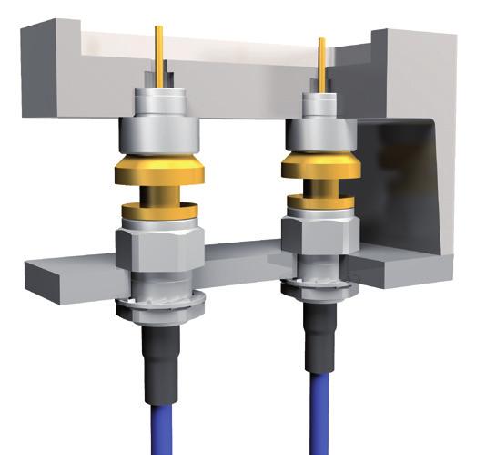
16 Series MBX assembly and disassembly tool To assemble use this side To disassemble use this side HUBER+SUHNER type Item no. Packaging Operating instruction 74_Z Series MBX test boards MBX test board: PK_MBX_Testboard-1 The test board is a mechanically and electrically working board containing two MBX board-to-board connections. One MBX connection is a SMT (surfacemount technology) the other one is THT (through-hole technology). The board-to-board distance is 18 mm. Return loss (RL) and insertion loss (IL) of a MBX board-to-board connection can be measured via the SMA connectors. There are two additional pairs of distance holders enclosed. The MBX connection can be measured at the minimum (16.8 mm) and maximum (19.2 mm) board-toboard distance by exchanging the distance holders. MBX reference board: PK_MBX-Referenceboard-1 A reference board is available for insertion loss (IL) measurements of the MBX connection. The reference board has the same SMA connectors and the same board length as the test board. The difference between the insertion loss (IL) of the test board and the reference board results in the insertion loss (IL) of the MBX connection. There is no reference board for return loss (RL) measurements needed. For further information, please contact the HUBER+SUHNER representative in your country. 16
17 Series MFBX design guideline Working range (axial and radial) In mated condition, the two PCB connector have to be aligned within the dimension given for the axial and radial working range. The axial working range is ± 0.8 mm, the radial working range is ± 0.8 mm and allows a sufficient electrical and mechanical connection. Connecting range Recommendation HUBER+SUHNER recommends using guiding pins to align the boards within the connecting range and working range. Distance holders to maintain the axial misalignment within working range are also of benefit. HUBER+SUHNER provides outline drawings for every application with the relevant mechanical dimensions that need to be considered when designing-in MFBX. 3D STEP files are available on The two PCB connector have to be aligned within the dimension given for connecting range. The connecting range is ± 0.8 mm and is equivalent to the max. allowed misalignment between two PCB boards when mating. Blind mateability is given when keeping the misalignment of two boards within specified connecting range. Blind mateability depends on the funnel size, the barrel length and the angle of the barrel. The HUBER+SUHNER specified connecting range includes all these variables and guarantees therefore blind mateability. Connecting range Working range connecting range axial working range radial working range 17
18 Series MFBX technical data MFBX PCB connectors board-to-board / adaptors within series Electrical data Impedance Frequency range Dielectric withstanding voltage (at sea level) Working voltage (at sea level) Insulation resistance Contact resistance - centre contact - outer contact Return loss / VSWR RF-leakage (interface only) Power (at room temperature) Requirements 50 Ω DC GHz 1 kv rms, 50 Hz 330 V rms, 50 Hz 1 GΩ 5 mω 5 mω typical values for a board-to-board connection (measured on a board) axial misalignment DC GHz ± 0.8 mm ± 0.4 mm 60dB (DC 3.5 GHz) 20 db / db / 1.17 typical 130 W at 2.4 GHz for board-to-board typical 160 W at 2.4 GHz for board-to-panel Mechanical data Requirements Engagement force (slide-side) 15 N / 3.4 lbs Disengagement force (slide-side) 15 N / 3.4 lbs Durability (matings) 50 Axial float (misalignment) ± 0.8 mm Radial float (misalignment) ± 0.8 mm Environmental data Test conditions Temperature range C / F High temperature endurance IEC Rapid change of temperature IEC , Test Na Damp heat steady state IEC , Test Ca Vibration IEC , Test Fc Mechanical shock IEC , Test Ea Processing data Adherent to the print - shearing - pulling (vertical to PCB) Requirements 150 N / 33.7 lbs. 150 N / 33.7 lbs. Material data Connector parts Material Plating Centre contact brass / bronze / copper-beryllium alloy SUCOPRO gold plating Outer contact brass / bronze SUCOPRO gold plating / SUCOPLATE Body brass SUCOPRO gold plating / SUCOPLATE Insulators LCP / PTFE / PFA Funnel PA 18
19 Series MFBX technical data MFBX adaptors between series Electrical data Impedance Frequency range Dielectric withstanding voltage (at sea level) Working voltage (at sea level) Insulation resistance Contact resistance - centre contact - outer contact Return loss / VSWR (typical values) Requirements 50 Ω DC GHz 1 kv rms, 50 Hz 330 V rms, 50 Hz 1 GΩ 5 mω 5 mω 30 db (DC 3.5 GHz) Mechanical data Requirements Engagement force (slide-slide) max. 30 N / max. 6.7 lbs Disengagement force (slide-slide) 8 30 N / lbs Durability (matings) 500 Environmental data Test conditions Temperature range 55 to +155 C / 67 to +311 F High temperature endurance IEC Rapid change of temperature IEC , Test Na Damp heat steady state IEC , Test Ca Vibration IEC , Test Fc Mechanical shock IEC , Test Ea Material data Connector parts Material Plating Centre contact copper-beryllium alloy SUCOPRO gold plating Outer contact brass / bronze / copper-beryllium alloy SUCOPRO gold plating Body brass / bronze / copper-beryllium alloy SUCOPRO gold plating Insulators LCP / PTFE / PFA Some connectors may have a specification that differs from the above mentioned data. The products are designed and guaranteed to pass the above mentioned test procedures. Any additional or different requirement arising from specific applications or environmental conditions which is not covered by these test procedures is subject to request. 19
 0.6 Interface reference Installation refernce (.024) 0.6 Fig. 1 Fig. 2 Interface refernce HUBER+SUHNER type Item no. Packaging Soldering pad Fig.")
 Installation reference 4.95 (.194) 1.65 3.3 (.064) (.129) 5.95 (.234 SQ.) 0.8 (.031 SQ) 0.6 Interface reference (.024) Fig. 1 Fig. 2 0.7 (.027 DIA.) Installation reference 2.4 6.35 (.094) (.25) 0.")

20 Series MFBX PCB connectors Straight PCB jacks (female) Surface mount type SMT 9.2 (.362 DIA.) 0.6 (.023 DIA) Installation reference 3.3 (.129 ) 5.95 (.234 SQ.) 0.7 (.027 DIA.) 6.35 (.25) 2.6 (.102) Pull-in range 5.95 (.234 SQ.) 0.6 Interface reference Installation refernce (.024) 0.6 Fig. 1 Fig. 2 Interface refernce HUBER+SUHNER type Item no. Packaging Soldering pad Fig. 82_MFBX-S50-0-8/111_NE ML _MFBX-S50-0-8/111_NM tape&reel 82_MFBX-S50-0-6/111_NE 82_MFBX-S50-0-6/111_NM tape&reel 2 Through hole type THT 0.7 (.027 DIA.) Installation reference 4.95 (.194) (.064) (.129) 5.95 (.234 SQ.) 0.8 (.031 SQ) 0.6 Interface reference (.024) Fig. 1 Fig (.027 DIA.) Installation reference (.094) (.25) 0.6 (.024) 8.75 (.344) 2.6 (.102) Pull-in range Interface reference 9.2 (.362 DIA.) 5.95 (.234 SQ.) 0.8 (.031 SQ.) HUBER+SUHNER type Item no. Packaging Soldering pad Fig. 82_MFBX /111_NE ML _MFBX /111_NM tape&reel 82_MFBX /111_NE 82_MFBX /111_NM tape&reel 2 Series MFBX adaptor between series (.626) SW 5.5 (.217 AF.) 1/4-36 UNS - 2A HUBER+SUHNER type Item no. Packaging Interface 33_MFBX-SMA-50-1/111_NE MFBX plug (m) / SMA jack (f) 20

 31.55 (1.323) 25.2 (.992) 4 (.157 DIA.) 2.72 (.107 DIA.) 1.03 (.04 DIA.) 1.5 16.")

21 Series MFBX adaptors within series Straight adaptors Plug to plug (male) X 3.88 (.152 DIA.) HUBER+SUHNER type Item no. Packaging Board-to-board distance Adaptor length x 32_MFBX /111_NE mm / 0.74 in mm / 0.65 in. 32_MFBX /111_NH _MFBX /111_NE 32_MFBX /111_NH mm /0.79 in mm / 0.69 in. Series MFBX receptacles with solder end Receptacles, jack (female) (1.323) 25.2 (.992) 4 (.157 DIA.) 2.72 (.107 DIA.) 1.03 (.04 DIA.) (.059) (.659) 6 (.236) SW 9.5 (.374 HEX.) M 6 Installation reference Interface reference (.023) (.226) HUBER+SUHNER type Item no. Packaging Assembly instruction 22_MFBX /133_NY industrial 100 pcs screwed-in Series MFBX assembly tool HUBER+SUHNER type Item no. Packaging Operating instruction 74_Z
22 Series MMBX design guideline Working range (axial and radial) In mated condition, the two PCB connector have to be aligned within the dimension given for the axial and radial working range. The axial working range is ± 0.3 mm, the radial working range at a board-to-baord distance of 8 mm is ± 0.4 mm. The radial working range depends on the length of the adaptor: the longer the adaptor the higher the radial working range. Recommendation HUBER+SUHNER recommends using guiding pins to align the boards within the connecting range and working range. Distance holders to maintain the axial misalignment within working range are also of benefit. HUBER+SUHNER provides outline drawings for every application with the relevant mechanical dimensions that need to be considered when designing-in MMBX. 3D STEP files are available on Connecting range The two PCB connector have to be aligned within the dimension given for connecting range when mating. In order to guarantee a blind mateable connection, the tilted adaptor will be guided by the funnel of the opposite connector. The connecting range depends on the length of the adaptor and the pull-in range (size of the funnel). The connecting range in the example below is ± 0.8 mm for a pull-in range of 1.8 mm (see table below). If the funnel (pull-in range) is smaller than 0.95 mm, a blind mateable assembly process is not possible anymore. The radial working range (mated condition) can be different from the connecting range (mating process). The smaller value has to be considered for the design of the board-to-board connection (blind mateability). Connecting range Working range 22
23 Series MMBX technical data MFBX PCB connectors board-to-board / adaptors within series Electrical data Impedance Frequency range Dielectric withstanding voltage (at sea level) Working voltage (at sea level) Insulation resistance Contact resistance - centre contact - outer contact Return loss / VSWR RF-leakage (interface only) Power Requirements 50 Ω DC GHz 1 kv rms, 50 Hz 330 V rms, 50 Hz 1 GΩ 5 mω 1 mω typical values for a board-to-board connection board-to-board distance DC 2.5 GHz GHz 6.7 mm mm 20.0 mm 70 db (DC... 6 GHz) 60 db (6 GHz GHz) 26 db / db / db / 1.11 typical 260 W at 2.4 GHz at room temperature 25 db / db / db / 1.25 Mechanical data Requirements Engagement force (slide-side) 15 N / 3.4 lbs Disengagement force (slide-side) 15 N / 3.4 lbs Durability (matings) 100 Axial float (misalignment) ± 0.3 mm Radial float (misalignment) depending on the adaptor length ± 0.4 mm (at 6.7 mm board-to-board distance) ± 0.8 mm (at mm board-to-board distance) Environmental data Test conditions Temperature range 55 to +155 C / 67 to +311 F Climatic category 55 / 155 / 21 Thermal shock MIL-STD-202, method 107 G, condition B1 Moisture resistance MIL-STD-202, method 106 F Corrosion MIL-STD-202, method 101, condition B Vibration MIL-STD-202, method 204 D, condition A Processing data Adherent to the print - shearing - pulling (vertical to PCB) Requirements 150 N / 33.7 lbs. 150 N / 33.7 lbs. Material data Connector parts Material Plating Centre contact brass / bronze / copper-beryllium alloy SUCOPRO gold plating Outer contact brass / bronze SUCOPRO gold plating Body brass SUCOPRO gold plating Insulators LCP / PTFE / PFA 23
24 Series MMBX technical data MMBX cable connectors Electrical data Impedance Frequency range Dielectric withstanding voltage (at sea level) Working voltage (at sea level) Insulation resistance Contact resistance - centre contact - outer contact Return loss / VSWR (typical values) Requirements 50 Ω DC GHz 750 V rms, 50 Hz 250 V rms, 50 Hz 1 GΩ 5 mω 1 mω 30 db / 1.07 (DC GHz) 25 db / 1.12 ( GHz) Mechanical data Requirements Engagement force max. 30 N / max. 6.7 lbs Disengagement force N / lbs Durability (matings) 100 Environmental data Test conditions Temperature range 55 to +155 C / 67 to +311 F Climatic category 55 / 155 / 10 Thermal shock MIL-STD-202, method 107 G, condition B1 Moisture resistance MIL-STD-202, method 106 F Corrosion MIL-STD-202, method 101, condition B Vibration MIL-STD-202, method 204 D, condition A Material data Connector parts Material Plating Centre contact copper-beryllium alloy SUCOPRO gold plating Outer contact bronze / copper-beryllium alloy SUCOPRO gold plating Body brass SUCOPRO gold plating / SUCOPLATE Crimp ferrules E-copper SUCOPRO gold plating / gold / SUCOPLATE Insulators PTFE / PFA 24
25 Series MMBX technical data MMBX adaptors between series Electrical data Impedance Frequency range Dielectric withstanding voltage (at sea level) Working voltage (at sea level) Insulation resistance Contact resistance - centre contact - outer contact Return loss / VSWR (typical values) Requirements 50 Ω DC GHz 1 kv rms, 50 Hz 330 V rms, 50 Hz 1 GΩ 5 mω 1 mω 30 db / 1.07 (DC... 6 GHz) Mechanical data Requirements Engagement force max. 30 N / max. 6.7 lbs Disengagement force N / lbs Durability (matings) 500 Environmental data Test conditions Temperature range 55 to +155 C / 67 to +311 F Climatic category 55 / 155 / 10 Thermal shock MIL-STD-202, method 107 G, condition B1 Moisture resistance MIL-STD-202, method 106 F Corrosion MIL-STD-202, method 101, condition B Material data Connector parts Material Plating Centre contact copper-beryllium alloy SUCOPRO gold plating Outer contact brass / bronze / copper-beryllium alloy SUCOPRO gold plating Body brass / bronze / copper-beryllium alloy SUCOPRO gold plating Insulators LCP / PTFE / PFA Some connectors may have a specification that differs from the above mentioned data. The products are designed and guaranteed to pass the above mentioned test procedures. Any additional or different requirement arising from specific applications or environmental conditions which is not covered by these test procedures is subject to request. 25


26 Series MMBX PCB connectors Straight PCB jacks (female) Surface mount type SMT Fig. 1 Fig. 2 Fig. 3 HUBER+SUHNER type Item no. Packaging Soldering pad Notes Fig. 82_MMBX-S50-0-1/111_NE 82_MMBX-S50-0-1/111_NH 82_MMBX-S50-0-1/111_NM tape and reel ML 122 pull-in range 0.65 mm/ in 1 82_MMBX-S50-0-3/111_NE 82_MMBX-S50-0-3/111_NH 82_MMBX-S50-0-3/111_NM 82_MMBX-S /111_NE 82_MMBX-S /111_NH 82_MMBX-S /111_NM tape and reel tape and reel pull-in range 0.95 mm/ in 2 pull-in range 1.80 mm/ in 3 26


27 Series MMBX PCB connectors Straight PCB jacks (female) Through hole type THT Fig. 1 Fig. 2 Fig. 3 HUBER+SUHNER type Item no. Packaging Mounting hole Notes Fig. 82_MMBX /111_NE ML 15 pull-in range 0.65 mm/ in 1 82_MMBX /111_NH 82_MMBX /111_NM tape and reel 82_MMBX /111_NH pull-in range 0.95 mm/ in 2 82_MMBX /111_NE 82_MMBX /111_NH pull-in range 1.80 mm/ in 3 Straight PCB jacks (female), edge mount HUBER+SUHNER type Item no. Packaging Mounting hole 92_MMBX-S /111_NE 92_MMBX-S /111_NM tape and reel ML


28 Series MMBX PCB connectors Straight PCB plugs (male) Surface mount type SMT HUBER+SUHNER type Item no. Packaging Soldering pad 81_MMBX-S50-0-1/111_NE 81_MMBX-S50-0-1/111_NH 81_MMBX-S50-0-1/111_NM tape and reel ML 122 Through hole type THT Fig. 1 Fig. 2 HUBER+SUHNER type Item no. Packaging Mounting hole Fig. 81_MMBX /111_NE ML _MMBX /111_NH 81_MMBX /111_NM tape and reel 81_MMBX /111_NM tape and reel 2 28


29 Series MMBX adaptors within series Straight adaptors Plug to plug (male) HUBER+SUHNER type Item no. Packaging Board-to-board distance 32_MMBX /111_NE 32_MMBX /111_NY industrial 200 pcs. Adaptor length X Min. pull-in range 6.7 mm/0.264 in 4.8 mm/0.189 in 0.65 mm/0.026 in * 32_MMBX /111_NH mm/0.315 in 6.0 mm/0.236 in 0.95 mm/0.037 in 32_MMBX /111_NE 32_MMBX /111_NY industrial 300 pcs mm/0.394 in 8.0 mm/0.315 in 1.80 mm/0.071 in 32_MMBX /111_NE mm/0.472 in 10.0 mm/0.417 in 1.80 mm/0.071 in 32_MMBX /111_NE 32_MMBX /111_NY industrial 200 pcs mm/0.551 in 12.0 mm/0.472 in 1.80 mm/0.071 in 32_MMBX /111_NY industrial 200 pcs mm/0.591 in 13.0 mm/0.512 in 1.80 mm/0.071 in * Only suitable pull-in-range. Adaptors with other lengths available upon request. Series MMBX test boards MMBX test board: EK_MMBX-2 The test board is a mechanically and electrically working board containing a surface mount MMBX board-to-board connection. The board-to-board distance is 6.7 mm. Return loss (RL) and insertion loss (IL) of a MMBX board-to-board connection can be measured via the SMA connectors. With the help of additional distance holders the MMBX connection can also be measured at min. (6.4 mm) and max. (7.0 mm) board-toboard distance. MMBX reference board: PK_MMBX_Referenceboard-1 A reference board with same SMA connectors and the same microstrip length as the test board is available for insertion loss (IL) measurements of the MMBX connection itself. The difference between the insertion loss (IL) of the test board and the reference board results in the insertion loss (IL) of the MMBX connection. There is no reference board for return loss (RL) measurements needed. For further information, please contact the HUBER+SUHNER representative in your country. 29
 Packaging Assembly instruction Crimp insert 11_MMBX-50-2-2/111_NE 23001744 U4 (EF_316_D) 27351 1 / A Right angle cable plugs (male)")
 Packaging Assembly instruction Crimp insert 16_MMBX-50-2-2/111_NE 16_MMBX-50-2-2/111_NH 23001746 84028931 U4 (EF_316_D) 27352 A Receptacles")
30 Series MMBX cable connectors Straight cable plugs (male) HUBER+SUHNER type Item no. Cable group (example) Packaging Assembly instruction Crimp insert 11_MMBX /111_NE U4 (EF_316_D) / A Right angle cable plugs (male) HUBER+SUHNER type Item no. Cable group (example) Packaging Assembly instruction Crimp insert 16_MMBX /111_NE 16_MMBX /111_NH U4 (EF_316_D) A Receptacles with solder end Receptacle, jack (female) Fig. 1 Fig. 2 HUBER+SUHNER type Item no. Packaging Assembly instruction Fig. 22_MMBX /111_NE screwed-in 1 22_MMBX /111_NY industrial 100 pcs. pressed-in 2 30


/sma plug (m) HUBER+SUHNER Packaging Interface")
31 Series MMBX assembly and disassembly tools Fig. 1 Fig. 2 HUBER+SUHNER type Item no. Packaging Operating instruction Fig. 74_Z _Z Adaptors between series HUBER+SUHNER type Item no. Packaging Interface 31_MMBX-SMA-50-1 / 111_NE MMBX jack (f)/sma jack (f) HUBER+SUHNER type Item no. Packaging Interface 32_MMBX-SMA-50-1/119_NE MMBX plug (m)/sma plug (m) HUBER+SUHNER type Item no. Packaging Interface 33_MMBX-SMA-50-1/111_NE MMBX plug (m)/ SMA jack (f) HUBER+SUHNER type Item no. Packaging Interface 33_SMA-MMBX-50-1/119_NE SMA plug (m)/mmbx jack (f) 31
32 HUBER+SUHNER AG Radio Frequency Division Degersheimerstrasse Herisau Switzerland Phone Fax hubersuhner.com / HUBER+SUHNER is certified according to EN(AS) 9100, ISO 9001, ISO 14001, ISO/TS and IRIS. Waiver Fact and figures herein are for information only and do not represent any warranty of any kind.
SERIES MCX 50 MICRO MINIATURE CONNECTORS
 SERIES MCX 50 MICRO MINIATURE CONNECTORS DESCRIPTION CONTENT PAGE HUBER+SUHNER MCX micro miniature snap-on connectors offer you an excellent blend of size, weight, durability and performance for applications
Series PC 3.5 precision subminiature connectors
 Series PC 3.5 precision subminiature connectors Description Content HUBER+SUHNER PC 3.5 connectors are precision connectors for use in microwave applications up to 26.5 GHz. They are especially suitable
Our Most Important Connection is with You. SECTION 3. Board-to-Board: MMBX / SMP-MAX R223 / R222M
 SECTION 3 Board-to-Board: MMBX / R223 / R222M Contents MMBX Introduction... 3-4 Interface... 3-5 Characteristics... 3-6 Plugs... 3-7 PCB receptacles... 3-7 to 3-8 Adapters... 3-9 Demo board... 3-10 Panel
SMP / SMP-COM / SMP-MAX series R222
 3 SMP / SMP-COM / SMP-MAX series R222 SMP-MAX INTRODUCTION BOARD TO BOARD SOLUTIONS The Best Systems Radiall s engineers work with your engineers allowing us to develop the best competitively priced misalignment
Cannon 50 Ohm Connectors
 SMB / SMC Cannon's SMB Snap-on and SMC Screw-on subminiature coaxial connectors have been specifically engineered for high performance and high reliability applications in both military and commercial
SMP. Description. Compatibility. Content. Interface dimensions (mm/inches) SMP female. Interface dimensions conformable to the following standards:
 SMP female. Interface dimensions conformable to the following standards:") Description Compatibility HUBER+SUHNER Astrolab connectors provide a robust, proven and fully compatible plug-in solution for applications up to 40 GHz. HUBER+SUHNER Astrolab connectors have been MIL-SPEC
Description Compatibility HUBER+SUHNER Astrolab connectors provide a robust, proven and fully compatible plug-in solution for applications up to 40 GHz. HUBER+SUHNER Astrolab connectors have been MIL-SPEC
Mating Interfaces 1,63 (.064) 3,45 (.135) Ø3,71 (.146) MAX Ø6,61 (.260) MAX Ø3,71 (.146) MAX
 3,45 (.135) Ø3,71 (.146) MAX Ø6,61 (.260) MAX Ø3,71 (.146) MAX") SMB / SMC Cannon's SMB Snap-on and SMC Screw-on subminiature coaxial connectors have been specifically engineered for high performance and high reliability applications in both military and commercial
SMB / SMC Cannon's SMB Snap-on and SMC Screw-on subminiature coaxial connectors have been specifically engineered for high performance and high reliability applications in both military and commercial
SECTION 12 SSMA/SSMB/SSMC R121/R203/R202 SIMPLIFICATION IS OUR INNOVATON. Visit for more information
 SECTION 12 SSMA/SSMB/SSMC R121/R203/R202 SIMPLIFICATION IS OUR INNOVATON Visit www.radiall.com for more information Contents SSMA Introduction... 12-4 Characteristics... 12-4 Plugs... 12-5 Receptacles...
Ganged Board to Board SMP Solutions. Catalog. belfuse.com/cinch
 Ganged Board to Board SMP Solutions Catalog belfuse.com/cinch SMP CONNECTORS One of the key benefits of the SMP connector interface is its use in high frequency blind-mate applications. The design of the
SMA Series. Specification. Description. Applications Civil & Military Telecommunication Instrumentation SMA SMA. Interface Mating Dimensions
 Series Specification 50 ohm 0-18 GHZ connectors are adaptable to interconnection requirements of both systems and components. S-Conn offers a wide variety of cable connectors, receptacles, feed thrus,
SECTION 1 IMP / UMP R107
 1 SECTION 1 / UMP R107 Contents Introduction... 1-4 to 1-6 Characteristics...1-7 Board to board connectors...1-8 Receptacle packaging...1-9 Assembly instructions... 1-9 to 1-10 UMP Characteristics...1-11
MCX Connectors. Alphabetical Index. Johnson Components P.O. Box 1732 Waseca, MN Fax:
 MCX Connectors Alphabetical Index 133-3701-201 3 133-3701-206 3 133-3701-211 3 133-3701-216 3 133-3701-221 3 133-3701-226 3 133-3701-231 4 133-3701-236 4 133-3701-301 5 133-3701-306 5 133-3701-311 5 133-3701-316
Prices, specifications, statement of warranty, and other terms and conditions are subject to change without notice by Lighthorse Technologies, Inc.
 Section Index Connectors Specifications... 93 Flexible Cable... 95 Panel Mount... 99 Bulkhead... 100 PCB Mount... 101 In Series Adaptors... 103 Other Information Assembly Instructions... 176 Cable Assembly...
SMA Connectors Series
 SMA Connectors Series Content Page Description.. 2 Interface Dimensions.. 2 Interface Dimensions in mm/inches.. 2 Characteristics. 3 Cable Connectors 4 PCB Connectors 11 Panel Receptacles.. 13 Adapter
Product Specification. Mezza-pede SMT Connector Low Profile 1.0mm Pitch
 Mezza-pede SMT Connector Low Profile 1.0mm Pitch Rev. 1 December 7, 2016 1.0 Scope This product specification applies to 1.0mm pitch Mezza-pede SMT Connectors, designed for the mating and unmating of a
SMA Connectors. RF Coax Connectors. Product Facts
 SMA Connectors Product Facts Performance to 12.4 GHz and beyond Available in various base metal options, including stainless steel, brass and zinc diecast Uses industry standard crimp tools and processes
SMA - 50 Ohm Connectors
 Alphabetical Index 142-0701-201 4 142-0701-206 4 142-0701-231 4 142-0701-235* 4 142-0701-236 4 142-0701-301 5 142-0701-306 5 142-0701-335* 6 142-0701-421 5 142-0701-426 5 142-0701-491 5 142-0701-496 5
SMA - 50 Ohm Connectors
 142-0701-621 4 142-0701-626 4 142-0701-631 4 142-0701-636 4 142-0701-701 7 142-0701-706 7 142-1701-011 5 142-1701-016 5 142-1701-031 4 142-1701-036 4 142-1701-041 5 142-1701-046 5 142-1701-121 5 142-1701-126
SMP connectors. the easy connection. Products overview. Applications
 Products overview PCB mount SMD mount plug and Centre pin in SMD, BGA or throughhole configurations Surface mount technology plug and Centre pin in SMD, BGA or throughhole configurations Bulkhead mount
Series SMPM-T. Description. Compatibility. Content. Interface dimensions (mm/inches) SMPM-T male (pin contact), smooth bore
 SMPM-T male (pin contact), smooth bore") Series Description The is the smallest threaded open source connector on the market. Its unique and innovative combination of a MIL- STD-348 SMPM female interface connector together with a retractable
Series Description The is the smallest threaded open source connector on the market. Its unique and innovative combination of a MIL- STD-348 SMPM female interface connector together with a retractable
TNC SERIES Miniature Coaxial Connectors
 SERIES Miniature Coaxial Connectors FEATURES connectors, medium sized coaxial connectors with thread coupling, are designed for applications where extreme vibration is encountered.the increased rigidity
SMA SERIES COAXIAL CONNECTORS
 General Information Features Part Number Index Applications Coupling types and interface mating dimensions Semi-rigid conformable cable connectors Flexible cable connectors Connectors for modules Bulkhead
Series 3402 lightning EMP protectors Gas discharge tube (GDT) technology up to 2.5 GHz
 technology up to 2.5 GHz") lightning EMP protectors Gas discharge tube (GDT) technology up to 2.5 GHz Description HUBER+SUHNER gas discharge tube protectors make the best of the traditional spark gap protection principle for general
lightning EMP protectors Gas discharge tube (GDT) technology up to 2.5 GHz Description HUBER+SUHNER gas discharge tube protectors make the best of the traditional spark gap protection principle for general
INCHES (MILLIMETERS) CUSTOMER DRAWINGS AVAILABLE ON REQUEST
 CUSTOMER DRAWINGS AVAILABLE ON REQUEST") TNC Connectors Flexible Cable... 3 In-Series Adapters... 4 Specifications... 2 RF Adapter Kit Adapters... 6 N Connectors Panel Mount and In-Series Adapters... 10 Flexible Cable... 8 Specifications... 7
TNC Connectors Flexible Cable... 3 In-Series Adapters... 4 Specifications... 2 RF Adapter Kit Adapters... 6 N Connectors Panel Mount and In-Series Adapters... 10 Flexible Cable... 8 Specifications... 7
Corona 70,000 Ft. Permeability Risetime Degradation (Mated Pair) 2.0 max MH z
 2.0 max MH z") NDL Ultraminiature Triaxial Connectors Connector Specifications Interface Dimensions Ø.020 Ø.082 Ø.168 Ø.162 Electrical Specifications Dielectric Center contact to intermediate contact: 1000 Vrms min Withstanding
NDL Ultraminiature Triaxial Connectors Connector Specifications Interface Dimensions Ø.020 Ø.082 Ø.168 Ø.162 Electrical Specifications Dielectric Center contact to intermediate contact: 1000 Vrms min Withstanding
Connectors. High Performance to 65 GHz. Applications. PDF Volume 1. Click Here for Table of Contents Click Here for Specifications
 SMP/SMPM Applications DELTA ELECTRONICS MANUFACTURING CORP. Connectors High Performance to 65 GHz PDF Volume 1 Click Here for Table of Contents Click Here for Specifications (978) 927-1060 FAX (978) 922-6430
GMS Interconnect Series Product Information
 GMS Interconnect Series Product Information Microwave Products Product Features: Frequency range: DC up to 23 GHz, Force to engage/disengage: 10 ounces min./2.5 pounds max., Male connectors have full self-centering
Cable Connectors SUHNER MCX 50 Ω. Straight Cable Plugs (male)
") Cable Connectors Straight Cable Plugs (male) > for semi-rigid cables, SUCOFORM and MULTIFLEX cables > cable entry soldered Assembly Instruction 11 MCX-50-1-14 / 111 NE 23032081 Y2 (EZ 47) single SUCOPRO
Cable Connectors Straight Cable Plugs (male) > for semi-rigid cables, SUCOFORM and MULTIFLEX cables > cable entry soldered Assembly Instruction 11 MCX-50-1-14 / 111 NE 23032081 Y2 (EZ 47) single SUCOPRO
The Custom Interconnect Leader
 7-16 Series.354.276.843.811 ELECTRICAL Nominal Impedance: Frequency Range: Voltage Rating: Dielectric Withstanding Voltage: Insulation Resistance: VSWR: Intermodulation: 50 ohms DC to 7 GHz 2,700 volts
 N Series Connectors Medium sized connector for high-voltage applications Suited for critical applications and environments Performance to 11 GHz (commercial) and 18 GHz (hi frequency) Intermateable with
Series 3400 lightning EMP protectors Quarter-wave stub technology
 Series 3400 lightning EMP protectors Quarter-wave stub technology Description HUBER+SUHNER quarter-wave lightning EMP protectors offer the best lightning protection available in the market, as they form
In-Series and Between-Series Adapters SMA
 Adapters SMA In-Series and Between-Series Adapters SMA If your choice of SMA Adapter is not shown in this section, please refer to the Table below to determine other possible locations. Should you not
OSMP Microminiature Push-On Coaxial Connectors
 Introduction Features Intermateable with Gilbert GPO Series Enhanced performance features Simplified ssembly etween Series dapters For OSMP etween Series dapters, see Page 438. OSMP microminiature push-on
Type SMP Connectors Product Catalog
 Type SMP Connectors Product Catalog Connectivity for SMP Connectors Table of Content Connectivity for Table of Contents PAGE Introduction....................................3-4 Specifications...................................5-8
N Connectors Specifications Flexible Cable Semi-Rigid Cable Panel Mount Bulkhead In Series Adaptors...
 Section Index Connectors Specifications... 137 Flexible Cable... 139 Semi-Rigid Cable... 145 Panel Mount... 147 Bulkhead... 148 In Series Adaptors... 149 Other Information Assembly Instructions... 176
The Custom Interconnect Leader
 SC Series.337.307.040.003.085.194 MIN FLARE TO MEET GAGE TEST.276 MIN.549.781 ELECTRICAL Nominal Impedance: Frequency Range: Voltage Rating: Dielectric Withstanding Voltage: Insulation Resistance: VSWR:
FISCHER MINIMAX TM SERIES
 TECHNICAL SPECIFICATIONS FISCHER TM SERIES Fischer Connectors SA All rights reserved Web version 1.0-03.2016 Changes without prior notice FISCHER TM SERIES KEY FEATURES The Fischer MiniMax Series increases
PGA / BGA / PLCC SOCKETS
 PGA / BGA / PLCC SOCKETS QUICK SELECTOR CHART PGA / BGA / PLCC PGA BGA PLCC GRID 2.54 mm INTERSTITIAL 1.27 mm 1.27 mm 1 mm SOCKETS Solder tail 156 161 165 SEE PAGE 173 Surface mount 156 161 165 166 169
Product Performance Specification Mini Coaxial Connector
 Product Performance Specification Mini Coaxial Connector 1. Scope 1.1 Content This specification covers the performance, tests and quality requirements for the Mini Coaxial connector and connector system.
SSL 1.1 Series. Product Data Sheet REV. 4, 2014 JUN
 SSL 1.1 Series Product Data Sheet REV. 4, 2014 JUN General Specification Number of Positions Current Rating 2, 4, 6P 3A (Max) Voltage Rating Dielectric Withstand Voltage Durability Color Operating Temperature
2.92mm (SMK) Connectors
 Connectors") 2.92mm (SMK) Connectors Catalog belfuse.com/cinch The Johnson 2.92mm Connector provides an excellent solution for demanding applications requiring high frequency transmission. Although similar to the SMA
2.92mm (SMK) Connectors Catalog belfuse.com/cinch The Johnson 2.92mm Connector provides an excellent solution for demanding applications requiring high frequency transmission. Although similar to the SMA
SPRING - LOADED CONNECTORS
 SPRING - LOADED CONNECTORS SPRING LOADED CONNECTORS QUICK SELECTOR CHART SPRING-LOADED CONNECTORS AND PAD CONNECTORS GRID 1.25 mm 2.54 mm SINGLE ROW SINGLE ROW DOUBLE ROW SLC CONNECTORS SEE PAGE Straight
SECTION 7 SMA/SMA-COM/BMA R125/R124/R128 SIMPLIFICATION IS OUR INNOVATON. Visit for more information
 SECTION 7 /COM/BMA R125/R124/R128 SIMPLIFICATION IS OUR INNOVATON Visit www.radiall.com for more information Contents BMA Introduction... 74 Characteristics... 75 Plugs... 76 Jacks... 77 to 78 Receptacles...78
SSMP Interconnect Series
 SSMP Interconnect Series INTRODUCTION Carlisle Interconnect Technologies (CarlisleIT) designed the SSMP connector product line to further improve package density of RF/Microwave systems. The SSMP interface
SMA Series - Crimp Plug and Jack
 Plug Features: SMA connectors are semi-precision, subminiature devices that provide repeatable electrical performance. These devices offer broadband performance with low reflection. These properties, along
PERFORMANCE SPECIFICATION ADAPTER, CONNECTOR, COAXIAL, RADIO FREQUENCY, (BETWEEN SERIES SMA TO SERIES TNC), CLASS 2, STRAIGHT PLUG
, CLASS 2, STRAIGHT PLUG") INCH POUND MIL-PRF-55339/48B w/amendment 1 15 June 2017 SUPERSEDING MIL-PRF-55339/48B 30 April 2015 PERFORMANCE SPECIFICATION ADAPTER, CONNECTOR, COAXIAL, RADIO FREQUENCY, (BETWEEN SERIES SMA TO SERIES
INCH POUND MIL-PRF-55339/48B w/amendment 1 15 June 2017 SUPERSEDING MIL-PRF-55339/48B 30 April 2015 PERFORMANCE SPECIFICATION ADAPTER, CONNECTOR, COAXIAL, RADIO FREQUENCY, (BETWEEN SERIES SMA TO SERIES
VITA 67 Series. Ideal For Blind Mate Applications. Electrical, Mechanical & Environmental Specifications
 VITA 67 Series Delta Electronics Manufacturing Corp. introduces 4 position (VITA 67.1) and 8 position (VITA 67.2) RF connector housings designed for 3U and 6U formats within the OpenVPX architecture. Ideal
Applications & Features, Type SSMP When using blind mate connectors in an application, careful consideration has to be given to choosing the right con
 SSMP Push-On Connectors & Adapters THE SSMP (Sub-Sub-Miniature-Push-On) is a 1.7 mm connector, using solid dielectric interface. The connector is 70% of the size of the SMP and therefore allows even higher
ndl-q & ndl-t SerieS CONNECTORS
 ndl-q & ndl-t SerieS CONNECTORS TRIAXIAL CONNECTORS Interface Dimensions Mechanical & Environmental Specifications (Ø.168) Temperature Rating Corrosion -65 C to + 165 C MIL-STD-202 Method 101, Test Condition
PC Board Sockets. Specifications SOCKETS. Surface Mount, Single Piece construction. Throughboard, Two Piece construction. Materials.
 Sockets Contents SMT PCB Sockets Sockets For Ø0.5mm Pin Sockets For Ø0.8mm Pin Sockets For Ø1mm Pin Sockets For Ø2mm Pin Test Sockets IC Socket Strip Dual Row IC Socket Surface Mount, Single Piece construction
AMPMODU* MOD I Interconnection System
 Product Specification AMPMODU* MOD I Interconnection System 03 JUN 2013 Rev E All Paragraphs Revised 1. SCOPE This specification covers performance and test requirements for the AMPMODU MOD I Interconnection
Product Performance Specifications QuadraPaddle Connector
 Product Performance Specifications QuadraPaddle Connector 1. Scope 1.1 Content This specification covers the performance, tests and quality requirements for the QuadraPaddle Connector and connector system.
REFERENCE PLANE Referenzebene
 1Series RPC- 2.92 Interface Dimensions Series RPC-2.92 (code 02) D REFERENCE PLANE Referenzebene REFERENCE PLANE Referenzebene D A E B C F F C B E A MALE Stecker FEMALE Kuppler Series RPC-2.92 Male Stecker
SMA. Precision 26.5GHz Connectors
 SMA Precision 26.5GHz Connectors SMA Precision Connectors SMA subminiature connectors are 50 ohm precision connectors initially designed for performance through 18GHz, however the standard interface is
Microwave Gilbert Push-on Interconnects
 Microwave Gilbert Push-on Interconnects Table of Contents Table of Contents Connect to Precision and Performance 4 Custom Designs 5 Corning Optical Communications RF LLC 6 Reference Guide 8 GPO Products
07. har-link INTERFACE CONNECTORS
 . INTERFACE CONNECTORS The highest data rates in combination with perfect shielding characterize the connector. This way data can be passed on optimally within the control cabinet. The locking mechanism
SPECIFICATION AND PERFORMANCE CHARACTERISTICS OF DVI MALE AND FEMALE CONNECTOR SERIES
 SPECIFICATION AND PERFORMANCE CHARACTERISTICS OF DVI MALE AND FEMALE CONNECTOR SERIES CIRCUIT ASSEMBLY CORP. 18 THOMAS STREET, IRVINE, CA 92618-2777 Page No. 1 CONTENTS CLAUSE PAGE 1.0 SCOPE.. 3 2.0 APPLICABLE
Thermal vacuum testing
 Thermal vacuum testing SUCOFLEX TVAC Edition 2013 For thermal vacuum applications Your partner for system solutions HUBER+SUHNER works as a partner to develop invative solutions for specific customer needs.
Extract from new. Device Connectivity catalogue. HARTING har-flex. People Power Partnership
 Extract from new Device Connectivity catalogue HARTING har-flex People Power Partnership . har-flex CONNECTORS The continuous scalability by an even number of contacts, i.e. from 6 to 100, of the HARTING
SMK Connectors. General Description. Contents (Click on any line to go to the indicated page) Test Data
 Test Data") SMK Connectors General Description These high-performance SMK (2.92 mm) connectors feature maximum VSWR for cable connectors of 1.15:1 from DC to 18 GHz, and 1.3:1 from 18 to 40 GHz. The maximum VSWR for
SMK Connectors General Description These high-performance SMK (2.92 mm) connectors feature maximum VSWR for cable connectors of 1.15:1 from DC to 18 GHz, and 1.3:1 from 18 to 40 GHz. The maximum VSWR for
07. har-link Interface Connectors
 . Interface Connectors The highest data rates in combination with perfect shielding characterize the connector. This way data can be passed on optimally within the control cabinet. The locking mechanism
AXOMACH E-16. High data rate links for faster data transmission. Microwave coaxial cables. Panel mount connector QUASI-FLEX. Cable mount connector 2
 AXOMACH High data rate links for faster data transmission AXON proposes AXOMACH, a range of high data rate links composed of low loss microwave coaxial cables and different connector types: AXOMACH Micro-D
07. har-link Interface Connectors
 . Interface Connectors The highest data rates in combination with perfect shielding characterize the connector. This way data can be passed on optimally within the control cabinet. The locking mechanism
SPRING-LOADED CONNECTORS PAD CONNECTORS
 SPRING-LOADED CONNECTORS PAD CONNECTORS GENERAL SPECIFICATIONS The values listed below are general specs applying for Preci-Dip spring-loaded connectors. Please see individual catalog page for additional
Fiber Optic. Connector accessories. Edition 2018/09
 Fiber Optic Connector accessories Edition 2018/09 Excellence in connectivity solutions Your partner for system solutions The HUBER+SUHNER Group is a leading global supplier of components and systems for
PRODUCT SPECIFICATION. This specification defines the detailed requirements for the Minitek Pwr3.0 wire to wire and wire to board connectors.
 s-12-1177*1.0 SCOPE 1 of 8 D This specification defines the detailed requirements for the Minitek Pwr3.0 wire to wire and wire to board connectors. 2.0 APPLICABLE DOCUMENTS The following documents, of
DUBOX SHUNTS BOARD/WIRE-TO-BOARD CONNECTORS FEATURES & BENEFITS. Dual-beam contacts for added reliability
 BOARD/WIRE-TO-BOARD CONNECTORS DUBOX SHUNTS FEATURES & BENEFITS Dual-beam contacts for added reliability Slotted cutout in low profile housing simplifies electrical testing Side-by-side and end-to-end
ES3 Series (WF2 Type) (culus Certified Product)
 (culus Certified Product)") COMPONENTS PRODUCT INFORMATION NEW Board-to Cable Connector For LED Lighting Power Supply ES3 Series (WF2 Type) (culus Certified Product) CONNECTOR MB-0227-3 July 2012 RoHS Compliant Receptacle (ES3B002WF2)
COMPONENTS PRODUCT INFORMATION NEW Board-to Cable Connector For LED Lighting Power Supply ES3 Series (WF2 Type) (culus Certified Product) CONNECTOR MB-0227-3 July 2012 RoHS Compliant Receptacle (ES3B002WF2)
Amphenol. Printed Circuit Board Technology NAFI + UHD CONNECTORS STANDARD. RELIABLE. PROVEN.
 Amphenol Printed Circuit Board Technology NAFI + UHD CONNECTORS STANDARD. RELIABLE. PROVEN. FEATURES & BENEFITS Available in 2 through 4 rows - Offers maximum design flexibility Tested and qualified to
TO FIND INDIVIDUAL SPECIFICATIONS OF STANDARD CONTACTS, PLEASE CONSULT OUR SEARCH ENGINE AT
 CONTACT TECHNOLOGY INTRODUCTION Preci-Dip, a world wide leading manufacturer of precision machined contacts and related interconnect components is continuously improving its ability to design innovative
Product Performance Specification Mini Power Connector
 Product Performance Specification Mini Power Connector 1. Scope 1.1 Content This specification covers the performance, tests and quality requirements for the Mini Power Connector and connector system.
EN3 SERIES WEATHERTIGHT CONNECTORS NEW PRODUCT BULLETIN 602
 FEATURES & BENEFITS Sealed to IP68 NEMA 250 (6P) Patented grommet & o-ring free design Available in ribbed or winged coupling ring Cable, panel & cable to cable options Gold plated contacts standard Solder,
BMA. 1. Applications & Features, Specifications & Interface Dimensions 2. Connectors of Type BMA 3. Adapters to BMA
 CONTENT BMA INTRODUCTION to CONNECTORS & ADAPTERS Page 9 7/16 Page 15 N BMA Page 45 SBX SBY Page 61 Page 85 1. Applications & Features, Specifications & Interface Dimensions 2. Connectors of Type BMA 37
Interface Connectors for Portable Terminal Devices
 Interface Connectors for Portable Terminal Devices ST Series Overview The ST Series interface connectors are specifically designed for use as Input/Output (I/O) connectors on portable information devices.
Ultra-Small Surface Mount Coaxial Connectors mm Mated Height
 All non- products have been discontinued, or will be discontinued soon. the products status on the Hirose website search at www.hirose-connectors.com, or contact your Hirose sales representative. NEW Ultra-Small
HIGH POWER HOT PLUGGABLE INTERCONNECTION SYSTEM. US Patent # 6,299,492 B1 2. POWER, RIGHT ANGLE EARLY 3. POWER, RIGHT ANGLE EARLY
 HIGH POWER HOT PLUGGABLE INTERCONNECTION SYSTEM US Patent # 6,299,492 B1 The HOTMATE board to board interconnection system provides a unique method of transferring hot pluggable power requirements within
RF & MW Connectors RF & MW Adapters RF Connectivity. RF & MW Connectors
 RF & MW Connectors - 2.4 mm Connectors - 2.92 mm(k) Connectors - Hermetic Seal (0.02 Glass Bead) - SMP Connectors - BMA Connectors - High Performance End Lanch Connectors - High Performance SMA Connectors
QSL RF Connector System
 QSL RF Connector System DESCRIPTION Coaxial Cable Insulation Displacement Interface Low profile Highly reliable ruggedized interface Surface mount technology Excellent price-to-performance ratio APPLICATIONS
PAGE 1/6 ISSUE SERIES Micro-SPDT PART NUMBER R516 X3X 10X R 516 _ 1 0 _
 PAGE 1/6 ISSUE 13-08-18 SERIES Micro-SPDT PART NUMBER R516 X3X 10X R516 series: the RAMSES concept merges with the SLIM LINE technology, breaking up the frequency limits of SMT switches : - FULL SMT TECHNOLOGY
2.6 GHz capable, 10 W carrying power (at 2.6 GHz), 50Ω/75Ω impedance and 1 Form C relays
, 50Ω/75Ω impedance and 1 Form C relays") .6 GHz capable, W carrying power (at.6 GHz), 5Ω/75Ω impedance and Form C relays RE RELAYS (ARE)..44..44 mm inch FEATURES Excellent high frequency characteristics (to.6ghz) Surface-mount type also available
.6 GHz capable, W carrying power (at.6 GHz), 5Ω/75Ω impedance and Form C relays RE RELAYS (ARE)..44..44 mm inch FEATURES Excellent high frequency characteristics (to.6ghz) Surface-mount type also available
Product Specification
 USB A CONNECTOR 1 of 7 J 1.0 GENERAL This specification defines the performance, tests and quality requirements for the USB A connector. This document is composed of the following sections. 1. General
Interface Connectors for Portable Terminal Devices
 Interface Connectors for Portable Terminal Devices ST Series Strong locking mechanism Right Mating axial direction Jan..0 Copyright 0 HIROSE ELECTRIC CO., LTD. All Rights Reserved. Overview The ST Series
PRODUCT SPECIFICATION
 1.0 SCOPE This Product Specification covers the 3.00 mm (.118 inch) centerline (pitch) square pin headers when mated with either printed circuit board (PCB) connector or connectors terminated with 20 to
Interface Connectors for Portable Terminal Devices
 Interface Connectors for Portable Terminal Devices ST Series Strong locking mechanism Right Mating axial direction Overview The ST Series interface connectors are specifically designed for use as Input/Output
Amphenol. Printed Circuit Board Technology NAFI + UHD CONNECTORS STANDARD. RELIABLE. PROVEN.
 Amphenol Printed Circuit Board Technology NAFI + UHD CONNECTORS STANDARD. RELIABLE. PROVEN. UHD FEATURES & BENEFITS 0.100 x 0.050 staggered grid - High density optimizes trace routing through the backplane
triaxial CONtaCts Overview Features
 triaxal CONtaCts triaxial CONtaCts Overview Smiths Connectors concentric twinax/triax contacts provide flexibility in the design of high speed data systems. The contacts, including the unique sizes 10
2.54mm Pitch Board to Board Connector
 All non-rohs products have been discontinued, or will be discontinued soon. Please check the products status on the Hirose website RoHS search at www.hirose-connectors.com, or contact your Hirose sales
SUBMINIATURE SERIES R 591. SUBMINIATURE SPnT up to 40 GHz. Our Most Important Connection is with You. SMA SMA 2.9 QMA
 PART Number Selection RF Connectors: 3: SMA up to 6 GHz 7: SMA up to 26.5 GHz 8: SMA 2.9 up to 40 GHz (6) E: QMA up to 6 GHz (5) Type: 0: Normally open 2: Latching, global reset 6: Latching, separated
MULTI ROTARY SWITCH MR50
 MAIN FEATURES 1 / 2 " SELECTOR SWITCH Dimensions Ø ½ (12.7 mm) Switching mode: Shorting or non-shorting 10, 12 and 16 selector switch positions Switching torque up to 6 Ncm Gold plated contacts Rugged
PERFORMANCE SPECIFICATION SHEET CONNECTORS, COAXIAL, RADIO FREQUENCY, SERIES C (UNCABLED-RECEPTACLE, FEMALE, JAM NUT MOUNTED, HERMETIC SEAL, CLASS 2)
") INCH-POUND MIL-PRF-39012/14C 10 August 2016 SUPERSEDING MIL-PRF-39012/14B 18 September 1977 PERFORMANCE SPECIFICATION SHEET CONNECTORS, COAXIAL, RADIO FREQUENCY, SERIES C (UNCABLED-RECEPTACLE, FEMALE,
INCH-POUND MIL-PRF-39012/14C 10 August 2016 SUPERSEDING MIL-PRF-39012/14B 18 September 1977 PERFORMANCE SPECIFICATION SHEET CONNECTORS, COAXIAL, RADIO FREQUENCY, SERIES C (UNCABLED-RECEPTACLE, FEMALE,
SPRING - LOADED CONNECTORS
 SPRING - LOADED CONNECTORS SPRING LOADED CONNECTORS Quick Selector Chart Spring-loaded connectors and Pad connectors TEL +1 32 21 0 00 2 mm 2.5 mm 3 35, 36 35, 36 Surface mount perpendicular with positioning
PRODUCT SPECIFICATION CUSTOM CONFIGURABLE MODULAR POWER DOCK CONNECTOR SYSTEM
 1.0 SCOPE This Product Specification covers the custom configurable modular printed circuit board (PCB) Dock Connector System with gold plating. 2.0 PRODUCT DESCRIPTION 2.1 PRODUCT NAME AND SERIES NUMBER(S)
Introduction. Purpose. Introduction to JAE s HDMI Connector, DC* Series
 Purpose Introduction Introduction to Objectives Application examples Main features General specifications Materials and finishes Content X pages Learning Time: X mins v1.0 1 JAE DC* Series HDMI Connector
QUICKIE SHROUDED HEADERS LOW PROFILE
 BOARD/WIRE-TO-BOARD CONNECTORS QUICKIE SHROUDED HEADERS LOW PROFILE FEATURES & BENEFITS Recessed pins assure proper alignment and eliminate damage during mating End windows for latching with IDC receptacle
3M 4-Wall, Tripolarized Header.050".100" Latch/Ejector, PTH & SMT Straight, PTH Right Angle 810 Series
 Tripolarized for robust alignment when mating to 820 series socket 50 mil 100 mil halves the connector length vs. traditional 100 mil x 100 mil products Latching Ejector for rugged high performance applications
USB 2.0 Standard Connectors
 USB 2.0 Standard Connectors UX Series Meets requirements of USB 2.0 Standard USB 2.0 certified Features 1. Compatible to USB 2.0 Standard The UX series connectors are certified by a certification organization
Amphenol High Density HDB 3 /HSB 3 Connectors
 Amphenol HDB 3 /HSB 3 Connectors TABLE OF CONTENTS Amphenol HDB 3 and HSB Connectors 3 Table of Contents..............................45 Introduction - Features, Options, Performance...............................
2mm Pitch Miniature Connector for HDD
 2mm Pitch Miniature Connector for HDD A3E Series type without polarizing guide type with polarizing guide Features 1. Variation in Number of Contacts This connector can be chosen according to applications,
BOARD-TO-BOARD HEADERS & RECEPTACLES
 TE Connectivity: Every Connection Counts 2015 TE Connectivity Ltd. family of companies. All Rights Reserved CONNECTORS BOARD-TO-BOARD HEADERS & RECEPTACLES TE CONNECTIVITY (TE) MICT,REC,038,ASY,.025,TAPE,CAP
Super Coaxial Micro-Plugs and Receptacles
 The GigaLane s Super coaxial Micro-Plugs (SCMP) and Receptacles (SCMJ) are specially designed for Space Reduction on Circuit Boards and for Vertical Mounting on RF Boards. They have the excellent RF performance