SAS to SAS/SATA JBOD Subsystem. User Manual. Revision 1.0
|
|
|
- Arlene Ryan
- 5 years ago
- Views:
Transcription
1 SAS to SAS/SATA JBOD Subsystem Revision 1.0
2 Table of Contents Chapter 1 Introduction Features Technical Specifications Terminologies... 6 Chapter 2 Getting Started Unpacking the JBOD Subsystem Identifying Parts of the JBOD Subsystem Front View Rear View JBOD Controller Module JBOD Controller Panel Power Supply Fan Module (PSFM) PSFM Panel LCD Display Panel LCD Panel LED LCD Panel Function Buttons Drive Carrier Module Disk Drive Status Indicators Drive Carrier Lock Indicator Chapter 3 Installation of JBOD Subsystem Powering On Disk Drive Installation Installing a SAS Disk Drive in a Disk Tray Installing a SATA Disk Drive (Dual JBOD Controller Mode) in a Disk Tray Connecting the JBOD Subsystem Connecting to RAID Subsystem Chapter 4 Quick Setup Management Interfaces LCD Control Module (LCM) Connecting JBOD to RAID Controller
3 Chapter 1 Introduction The 16 bays EPICa JBOD Subsystem The EPICa EP-3164J1/JD1-S6S6 is a 19-inch 3U 16 bays rackmount JBOD unit. It features the latest SAS II (6Gb/s) interface. It designed to fit in with the environments which needed highly reliable and relentless data growth. The EP- 3164J1/JD1-S6S6 is also a versatile SAS / SATA Disk Expansion system, ideal for high capacity and scalability storage in IT demands. Based on the 6G SAS technology, the EP-3164J1/JD1-S6S6 supports the choice of SAS and SATA drive configurations to deliver the best cost-performance index with higher bandwidth. 3
4 1.1 Features 16 hot-swappable drive bays in a rackmount 3U chassis Simultaneously support SAS or SATA disks Each SAS JBOD controller module consist of two 6G mini SAS (4x) port Power Supply and cooling system contained in 1 module for efficient cooling Two 460W redundant hot swappable power supplies Incorporates a cableless design for maximum signal integrity Utilizes industry-standard SCSI Enclosure Services to monitor enclosure and disk environmental conditions Enclosure monitoring S.E.S. support for standard enclosure management System LED indications Fan speed monitoring Power supply monitoring System voltage monitoring System temperature monitoring System alarm 4
5 1.2 Technical Specifications Model RAID Controller Controller Host Interface EP-3164J1/JD1-S6S6 JBOD Single/Dual One / Two 4x mini SAS (6Gb/s) Disk Interface SAS 3Gb/6Gb or SATA II/III * SAS expansion S.M.A.R.T. support Platform Form Factor One / Two 4x mini SAS (6Gb/s) Yes Rackmount 3U # of Hot Swap Trays 16 Tray Lock Disk Status Indicator Backplane Yes Access / Fail LED SAS / SATA Single BP # of PS/Fan Modules 460W x 2 w/pfc # of Fans 2 Power requirements Relative Humidity Operating Temperature Physical Dimension Weight (Without Disk) AC 90V ~ 264V Full Range, 10A ~ 5A, 47Hz ~ 63Hz 10% ~ 85% Non-condensing 10 C ~ 40 C (50 F ~ 104 F) 555(L) x 482(W) x 131(H) mm 19/20.5 Kg * Request optional dongle board for SATA II/III hard drive 5
6 1.3 Terminologies The document uses the following terms: Part 1: Common RAID JBOD SCSI SAS S.M.A.R.T. WWN HBA Redundant Array of Independent Disks. There are different RAID levels with different degree of data protection, data availability, and performance to host environment. The abbreviation of Just a Bunch Of Disks. JBOD needs at least one hard drive. Small Computer Systems Interface. Serial Attached SCSI. Self-Monitoring Analysis and Reporting Technology. World Wide Name. Host Bus Adapter. Part 2: Dual controller SBB Dongle Board Bridge Board Storage Bridge Bay. The objective of the Storage Bridge Bay Working Group (SBB) is to create a specification that defines mechanical, electrical and low-level enclosure management requirements for an enclosure controller slot that will support a variety of storage controllers from a variety of independent hardware vendors ( IHVs ) and system vendors. SATA Dongle board is for SATA II disk connection to the dual controller backplane. SAS-SATA Bridge board is for SATA II disk connection to the dual JBOD backplane. 6

 external Mini SAS cables SFF-8088 to SFF-8088 for dual controller")
7 Chapter 2 Getting Started 2.1 Unpacking the JBOD Subsystem The shipping package contains the following: JBOD Subsystem Unit Two (2) power cords One (1) external Mini SAS cable SFF-8088 to SFF-8088 for single controller Note: Two (2) external Mini SAS cables SFF-8088 to SFF-8088 for dual controller NOTE: If any damage is found, contact the dealer or vendor for assistance. 7


8 2.2 Identifying Parts of the JBOD Subsystem The illustrations below identify the various parts of the expansion chassis Front View 8


9 2.2.2 Rear View Single Controller Dual Controller 9

10 2.2.3 JBOD Controller Module JBOD Controller Module JBOD Controller Panel Part SAS In Port SAS Expansion Port Description Use to connect to RAID subsystem s SAS Expansion Port. Use to connect to the SAS In Port of another JBOD subsystem. 10
11 Indicator Color Description Master/Slave LED JBOD Status LED Link LED Access LED Green Green Blue Blinking Green Indicates the master controller; Off indicates the slave controller. Indicates controller status normal or in the booting state. Indicates expander has connected or linked. Indicates the expander is busy and being accessed. 2.3 Power Supply Fan Module (PSFM) The RAID subsystem contains two 460W Power Supply / Fan Modules. All the Power Supply / Fan Modules (PSFMs) are inserted into the rear of the chassis. 11

12 2.3.1 PSFM Panel The panel of the Power Supply/Fan Module contains: the Power On/Off Switch, the AC Inlet Plug, FAN fail Indicator, and a Power On/Fail Indicator showing the Power Status LED, indicating ready or fail. Each fan within a PSFM is powered independently of the power supply within the same PSFM. So if the power supply of a PSFM fails, the fan associated with that PSFM will continue to operate and cool the enclosure. FAN Fail Indicator If fan is failed, this LED will turn to RED and alarm will sound. Power On/Fail Indicator When the power cord connected from main power source is inserted to the AC Power Inlet, the power status LED becomes RED. When the switch of the PSFM is turned on, the LED will turn GREEN. When the Power On/Fail LED is GREEN, the PSFM is functioning normally. NOTE: Each PSFM has one Power Supply and one Fan. The PSFM 1 has Power#1 and Fan#1. The PSFM 2 has Power#2 and Fan#2. When the Power Supply of a PSFM fails, the PSFM need not be removed from the slot if replacement is not yet available. The fan will still work and provide necessary airflow inside the enclosure. NOTE: After replacing the Power Supply Fan Module and turning on the Power On/Off Switch of the PSFM, the Power Supply will not power on immediately. The Fans in the PSFM will spin-up until the RPM becomes stable. When Fan RPM is already stable, the RAID controller will then power on the Power Supply. This process takes more or less 30 seconds. This safety measure helps prevent possible Power Supply overheating when the Fans cannot work. 12


13 2.4 LCD Display Panel LCD Panel LED Parts Power LED Power Fail LED Function Green indicates power is ON. If one of the redundant power supply unit fails, this LED will turn to RED and alarm will sound. Fan Fail LED Over Temperature LED Voltage Warning LED Turn RED when fan fails. If disk temperatures exceed 65 o C, the Over Temperature LED will turn RED and alarm will sound. An alarm will sound if detected voltage in the controller is abnormal and LED will turn RED. 13

14 2.4.2 LCD Panel Function Buttons Parts Up and Down Arrow buttons Select button Exit button EXIT Function Use the Up or Down arrow keys to go through the information on the LCD screen. This is also used to move between each menu. This is used to enter the option you have selected. Press this button to return to the previous menu. 14
15 2.5 Drive Carrier Module The Drive Carrier Module houses a 3.5 inch hard disk drive. It is designed for maximum airflow and incorporates a carrier locking mechanism to prevent unauthorized access to the HDD Disk Drive Status Indicators Disk Activity Indicator Disk Status Indicator Part Disk Activity Indicator Function This LED will blink blue when the hard drive is being accessed. Disk Status Indicator Green LED indicates power is on and hard drive status is good for this slot. If hard drive is defective or failed, the LED is Red. LED is off when there is no hard drive. 15
16 2.5.2 Drive Carrier Lock Indicator Every Drive Carrier is lockable and is fitted with a lock indicator to indicate whether or not the carrier is locked into the chassis or not. Each carrier is also fitted with an ergonomic handle for easy carrier removal. Drive Carrier is unlocked When the Lock Groove is vertical, then the Drive Carrier is unlocked. Drive Carrier is locked When the Lock Groove is horizontal, this indicates that the Drive Carrier is locked. Lock and unlock the Drive Carriers by using a flat-head screw driver. 16
. The system will automatically select voltage. 2.")
17 Chapter 3 Installation of JBOD Subsystem 3.1 Powering On 1. Plug in the power cords into the AC Power Input Socket located at the rear of the subsystem. NOTE: The subsystem is equipped with redundant, full range power supplies with PFC (power factor correction). The system will automatically select voltage. 2. Turn on each Power On/Off Switch to power on the subsystem. 3. The Power LED on the front panel will turn green. 17


18 3.2 Disk Drive Installation This section describes the physical locations of the hard drives supported by the subsystem and give instructions on installing a hard drive. The subsystem supports hot-swapping allowing you to install or replace a hard drive while the subsystem is running Installing a SAS Disk Drive in a Disk Tray NOTE: These steps are the same when installing SATA disk drive in Single Controller Mode. 1. Unlock the Disk Trays using a flat-head screw driver by rotating the Lock Groove. 2. Press the Tray Open button and the Disk Tray handle will flip open. Tray Open Button 3. Pull out an empty disk tray. 18

19 4. Place the hard drive in the disk tray. Turn the disk tray upside down. Align the four screw holes of the SAS disk drive in the four Hole A of the disk tray. To secure the disk drive into the disk tray, tighten four screws on these holes of the disk tray. Note in the picture below where the screws should be placed in the disk tray holes. Tray Hole A NOTE: All the disk tray holes are labelled accordingly. 19
20 5. Slide the tray into a slot. 6. Press the lever in until you hear the latch click into place. The HDD Fault LED will turn green when the subsystem is powered on and HDD is good. 7. If necessary, lock the Disk Tray by turning the Lock Groove. 20


21 3.2.2 Installing a SATA Disk Drive (Dual JBOD Controller Mode) in a Disk Tray 1. Remove an empty disk tray from the subsystem. 2. Prepare the dongle board the Fixed Bracket, and screws. Fixed Bracket 6G Dongle Board Screws 3. Attach the dongle board in the Fixed Bracket with a screw. 21

22 4. Place the Fixed Bracket with the dongle board in the disk tray as shown. 22
23 5. Turn the tray upside down. Align the holes of the Fixed Bracket in the two Hole d of the disk tray. Tighten two screws to secure the Fixed Bracket into the disk tray. Tray Hole d NOTE: All the disk tray holes are labelled accordingly. 6. Place the SATA disk drive into the disk tray. Slide the disk drive towards the dongle board. 23
24 7. Turn the disk tray upside down. Align the four screw holes of the SATA disk drive in the four Hole B of the disk tray. To secure the disk drive into the disk tray, tighten four screws on these holes of the disk tray. Note in the picture below where the screws should be placed in the disk tray holes. Tray Hole B NOTE: All the disk tray holes are labelled accordingly. 8. Insert the disk tray into the subsystem. 24


25 3.3 Connecting the JBOD Subsystem Connecting to RAID Subsystem Attach one end of the SAS cable to the SAS IN Port of the JBOD controller module and the other end to the SAS Expansion Port on the RAID controller of RAID subsystem. If configured in redundant mode, connect the other SAS cable to the SAS IN Port of the other JBOD controller, and the other end to the SAS Expansion Port on the other RAID controller of RAID subsystem. RAID Subsystem JBOD Subsystem An Example of JBOD Subsystem Connection 25
26 Chapter 4 Quick Setup 4.1 Management Interfaces There is only one management method to manage the dual JBOD controller, described as follows: LCD Control Module (LCM) After booting up the system, the LCD display will show the JBOD subsystem model name and WWN (World Wide Name or SAS address): Model Name WWN Press ENT, the LCM functions Alarm From, Alarm Mute, Enclosure, and System Reset will rotate by pressing (up) and (down). The following table is function description of each item. LCM operation description: FW Version Alarm From Enclosure System Reset Shutdown Firmware version of controller. Alarm from power supply, cooling fan, thermal sensor or voltage sensor. Status of power supply, cooling fan, thermal sensor and voltage sensor. Reset controller. Shutdown controller. 26
27 LCM menu hierarchy: FW Version x.x.x [Alarm From] [Alarm From] xxxxxx Model Name / WWN [Enclosure] [Power Supply] Good/Fail [Cooling Fan] Good/Fail [Thermal Sensor] Good/Fail [Voltage Sensor] Good/Fail [ PSU1] [O/X] [ PSU2] [O/X] [ Fan 1] xxxx rpm [O/X] [ Fan 2] xxxx rpm [O/X] [ Temperature 1] xx [O/X] [ Temperature 2] xx [O/X] [ Temperature 3] xx [O/X] [ Temperature 4] xx [O/X] [ Voltage 1] x.xx V [O/X] [ Voltage 2] x.xx V [O/X] [ Voltage 3] x.xx V [O/X] [ Voltage 4] x.xx V [O/X] [ Voltage 5] x.xx V [O/X] [ Voltage 6] x.xx V [O/X] [ Voltage 7] x.xx V [O/X] [System Reset] [ Yes No ] [Shutdown] [ Yes No ] 27

28 4.2 Connecting JBOD to RAID Controller iscsi RAID controller suports SAS JBOD expansion to connect extra SAS dual JBOD controller. When connecting a dual JBOD controller which can be detected in RAID Subsystem management GUI, it will be displayed in Show PD for: under / Volume configuration / Physical disk menu. For example, Local, JBOD 1, JBOD 2, etc. Local means disks located in local RAID subsystem, JBOD 1 means disks located in first JBOD subsystem, and so on. The hard drives in JBOD can be used as local disks. 28

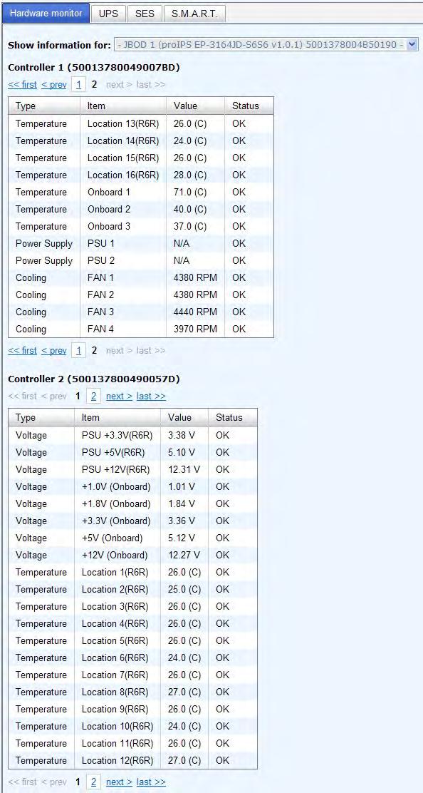
29 / Enclosure management / Hardware monitor can display the hardware status of SAS JBODs. 29
30 30

31 / Enclosure management / S.M.A.R.T. can display S.M.A.R.T. information of all PDs, including Local and all SAS JBODs. 31
SAS to SAS/SATA JBOD Subsystem. User Manual. Revision 1.1
 SAS to SAS/SATA JBOD Subsystem Revision 1.1 Table of Contents Chapter 1 Introduction... 3 1.1 Features... 4 1.2 Technical Specifications... 5 1.3 Unpacking the JBOD Expansion Chassis... 6 1.4 Identifying
SAS to SAS/SATA JBOD Subsystem. User Manual. Revision 1.1
 SAS to SAS/SATA JBOD Subsystem Revision 1.1 Table of Contents Chapter 1 Introduction... 3 1.1 Features... 4 1.2 Technical Specifications... 5 1.3 Unpacking the JBOD Expansion Chassis... 6 1.4 Identifying
SAS to SAS/SATA JBOD Subsystem. User Manual. Revision 1.2
 SAS to SAS/SATA JBOD Subsystem Revision 1.2 Table of Contents Chapter 1 Introduction... 3 1.1 Features... 4 1.2 Technical Specifications... 5 1.3 Unpacking the JBOD Subsystem... 6 1.4 Identifying Parts
64 Bays SAS to SAS/SATA JBOD Subsystem. User Manual. Revision 1.0
 64 Bays SAS to SAS/SATA JBOD Subsystem Revision 1.0 Table of Contents Preface... 4 Before You Begin... 5 Safety Guidelines... 5 Controller Configurations... 5 Packaging, Shipment and Delivery... 5 Unpacking
SAS JBOD Installation Reference Guide Revision 1.0
 SAS JBOD 16-bay Rackmount Enclosure Installation Reference Guide Revision 1.0 P/N: PW0020000000281 Copyright No part of this publication may be reproduced, stored in a retrieval system, or transmitted
SAS to SAS/SATA RAID Subsystem
 SAS to SAS/SATA RAID Subsystem Revision 1.0 Table of Contents Preface... 5 Before You Begin... 6 Safety Guidelines... 6 Controller Configurations... 6 Packaging, Shipment and Delivery... 6 Unpacking the
Rocsecure NE52 NAS System
 Rocsecure NE52 NAS System Revision 1.0 Table of Contents Preface... 3 Before You Begin... 4 Safety Guidelines... 4 Packaging, Shipment and Delivery... 4 Chapter 1 Introduction... 5 1.1 Key Features...
NAS System. User s Manual. Revision 1.0
 User s Manual Revision 1.0 Before You Begin efore going through with this manual, you should read and focus on the following safety guidelines. Information about the NAS system s packaging and delivery
Fibre to SAS/SATA RAID Subsystem
 Fibre to SAS/SATA RAID Subsystem Revision 1.0 Table of Contents Preface... 5 Before You Begin... 6 Safety Guidelines... 6 Controller Configurations... 6 Packaging, Shipment and Delivery... 6 Unpacking
SAS to SAS/SATA RAID Subsystem
 SAS to SAS/SATA RAID Subsystem Revision 1.0 Table of Contents Preface... 5 Before You Begin... 6 Safety Guidelines... 6 Controller Configurations... 6 Packaging, Shipment and Delivery... 6 Unpacking the
Fibre to SAS/SATA RAID Subsystem
 Fibre to SAS/SATA RAID Subsystem Revision 1.1 Table of Contents Preface... 5 Before You Begin... 6 Safety Guidelines... 6 Controller Configurations... 6 Packaging, Shipment and Delivery... 6 Unpacking
SAS to SAS/SATA RAID Subsystem
 SAS to SAS/SATA RAID Subsystem Revision 1.1 Table of Contents Preface... 5 Before You Begin... 6 Safety Guidelines... 6 Controller Configurations... 6 Packaging, Shipment and Delivery... 6 Unpacking the
RDL-AS24F8 RDL-AD24F8. 24 Bays Fibre to SAS/SATA II DISK Array
 RDL-AS24F8 RDL-AD24F8 24 Bays Fibre to SAS/SATA II DISK Array Revision 1.0 www.raiddeluxe.com Table of Contents Preface... 5 Before You Begin... 6 Safety Guidelines... 6 Controller Configurations... 6
FIBRE-to-SAS/SATA RAID SUBSYSTEM
 FIBRE-to-SAS/SATA RAID SUBSYSTEM Revision 1.4 Table of Contents Preface...6 Before You Begin...7 Safety Guidelines...7 Controller Configurations...7 Packaging, Shipment and Delivery...7 Unpacking the Subsystem...8
iscsi GbE to 6G SAS/SATA RAID Subsystem User Manual Revision 1.0
 iscsi GbE to 6G SAS/SATA RAID Subsystem Revision 1.0 Table of Contents Preface... 7 Before You Begin... 8 Safety Guidelines... 8 Controller Configurations... 8 Packaging, Shipment and Delivery... 8 Chapter
FC TO SAS / SATA RAID SUBSYSTEM
 FC TO SAS / SATA RAID SUBSYSTEM Hardware Reference Guide Revsision 1.0 P/N: PW0020000000238 Preface About this manual This manual provides information regarding the quick installation and hardware features
Fibre to SAS/SATA RAID Subsystem
 Fibre to SAS/SATA RAID Subsystem Revision 1.0 Table of Contents Preface... 5 Before You Begin... 6 Safety Guidelines... 6 Controller Configurations... 6 Packaging, Shipment and Delivery... 6 Unpacking
DNS-2608 Enterprise JBOD Enclosure User Manual
 DNS-2608 Enterprise JBOD Enclosure User Manual Nov.2017 Copyright DataON. All rights reserved. www.dataonstorage.com 1 Contents Package Contents... 3 System Requirements... 3 Technical Support... 3 DataON
DNS User Manual. Version Dec DataON Storage, storage division of Area Data Systems.
 DNS-2670 User Manual Version Dec. 2015 DataON Storage, storage division of Area Data Systems. Contents 1 Introduction... 1 1.1 System Overview... 3 1.1.1 System Top View...3 1.1.2 Front View...4 1.1.3
FIBRE-to-SAS/SATA RAID SUBSYSTEM
 FIBRE-to-SAS/SATA RAID SUBSYSTEM Revision 1.4 Table of Contents Preface...6 Before You Begin...7 Safety Guidelines... 7 Controller Configurations... 7 Packaging, Shipment and Delivery... 7 Chapter 1 Introduction...8
iscsi GbE to SAS/SATA II RAID Subsystem
 iscsi GbE to SAS/SATA II RAID Subsystem Revision 1.0 Table of Contents Preface... 6 Before You Begin... 7 Safety Guidelines... 7 Controller Configurations... 7 Packaging, Shipment and Delivery... 7 Chapter
Fibre to SAS/SATA RAID Subsystem
 Fibre to SAS/SATA RAID Subsystem Revision 1.0 Table of Contents Preface... 5 Before You Begin... 6 Safety Guidelines... 6 Controller Configurations... 6 Packaging, Shipment and Delivery... 6 Unpacking
iscsi GbE to SAS/SATA RAID Subsystem
 iscsi GbE to SAS/SATA RAID Subsystem Revision 1.0 Table of Contents Preface... 6 Before You Begin... 7 Safety Guidelines... 7 Controller Configurations... 7 Packaging, Shipment and Delivery... 7 Chapter
HighPoint NA381TB3. 4U 24 bay ( 3.5" / 2.5" ) Thunderbolt 3 Storage and PCIe Expansion. User Manual
 Thunderbolt 3 Storage and PCIe Expansion. User Manual") HighPoint NA381TB3 4U 24 bay ( 3.5" / 2.5" ) Thunderbolt 3 Storage and PCIe Expansion User Manual First edition, June. 2017 1. Overview 3 2. Package Checklist 3 3. Panel Layout 4 4. Hardware Configuration
HighPoint NA381TB3 4U 24 bay ( 3.5" / 2.5" ) Thunderbolt 3 Storage and PCIe Expansion User Manual First edition, June. 2017 1. Overview 3 2. Package Checklist 3 3. Panel Layout 4 4. Hardware Configuration
ETERNUS JX60. Technical Product Introduction. 0 Copyright Fujitsu, Release June 2014
 0 Copyright Fujitsu, Release June 2014 Highlights The passive storage subsystem accommodates up to 240 HDDs 3.5" SAS 2.0 Nearline SAS 7200 rpm, max. storage capacity 960 TB 1) One or two 6 Gbit/s SAS interfaces
12/16 Bays Fibre/SAS/iSCSI to SAS RAID Subsystem
 12/16 Bays Fibre/SAS/iSCSI to SAS RAID Subsystem Installation Guide Version 1.0 www.raiddeluxe.com RAID Subsystem Fibre/SAS/iSCSI to 6Gb/s SAS RAID Subsystem Installation Guide Version: 1.0 Issue Date:
3U 16-bay PCI-Express Rackmount JBOD Chassis. Installation Guide
 3U 16-bay PCI-Express Rackmount JBOD Chassis Installation Guide Package Checklist Before installing this unit, verify that package contains the following items: Enclosure x 1 HDD Tray x 16 (Installed in
TOWERSTOR TS25CT. QUICK INSTALLATION GUIDE v1.0
 TOWERSTOR TS25CT QUICK INSTALLATION GUIDE v1.0 Contents Preface... 2 Before You Begin... 3 Chapter 1 Introduction... 4 1.1 Technical Specification... 4 1.2 Identifying Parts of the RAID Subsystem...5 1.2.1
Netberg J224 M3 JBOD
 Netberg J224 M3 JBOD Netberg J224 M3 JBOD Table of Contents 1. Safety 1.1. 1.2. 1.3. Information... 1 Conventions... 2 Acronyms... 3 Safety Information... 6 1.3.1. Important Safety Instructions... 6 1.4.
NA381TB3. 4U 24 bay ( 3.5" / 2.5" ) Thunderbolt 3 Storage and PCIe Expansion. User Manual
 Thunderbolt 3 Storage and PCIe Expansion. User Manual") NA381TB3 4U 24 bay ( 3.5" / 2.5" ) Thunderbolt 3 Storage and PCIe Expansion User Manual First edition, June. 2017 1. Overview 3 2. Package Checklist 3 3. Panel Layout 4 4. Hardware Configuration 5 5. Building
NA381TB3 4U 24 bay ( 3.5" / 2.5" ) Thunderbolt 3 Storage and PCIe Expansion User Manual First edition, June. 2017 1. Overview 3 2. Package Checklist 3 3. Panel Layout 4 4. Hardware Configuration 5 5. Building
CHASSIS INSTALLATION GUIDE
 SUPER SC942S-600 SC942i-600/550 SC942 CHASSIS INSTALLATION GUIDE 1.0 SUPER SC942 Chassis User's Guide Table of Contents Chapter I: Unpacking and Check Lists... 1-3 Chapter 2: Installation Procedures...
Dell MD1280 Storage Enclosure Getting Started Guide
 Dell MD1280 Storage Enclosure Getting Started Guide Regulatory Model: SP-2584, E11J Notes, Cautions, and Warnings NOTE: A NOTE indicates important information that helps you make better use of your computer.
Dell EMC PowerVault MD3460 Storage Arrays
 Dell EMC PowerVault MD3460 Storage Arrays Owner's Manual Regulatory Model: E08J Series Regulatory Type: E08J001 Notes, cautions, and warnings NOTE: A NOTE indicates important information that helps you
apple Service Source Xserve RAID Xserve RAID and Xserve RAID (SFP) Updated: 25 May Apple Computer, Inc. All rights reserved.
 Updated: 25 May Apple Computer, Inc. All rights reserved.") apple Service Source Xserve RAID Xserve RAID and Xserve RAID (SFP) Updated: 25 May 2004 2003 Apple Computer, Inc. All rights reserved. apple Service Source Basics Xserve RAID 2003 Apple Computer, Inc.
apple Service Source Xserve RAID Xserve RAID and Xserve RAID (SFP) Updated: 25 May 2004 2003 Apple Computer, Inc. All rights reserved. apple Service Source Basics Xserve RAID 2003 Apple Computer, Inc.
3U16 SAS JBOD SS3001 / SS3002 USER S MANUAL
 3U16 SAS JBOD SS3001 / SS3002 USER S MANUAL Page: i Important Information Warranty Our product is warranted against defects in materials and workmanship for a period of one year from the date of shipment,
SAS to SATA II RAID Subsystem
 SAS to SATA II RAID Subsystem Revision 1.0 Table of Contents Preface... 5 Before You Begin... 6 Safety Guidelines... 6 Controller Configurations... 6 Packaging, Shipment and Delivery... 6 Unpacking the
Chassis (FRU) Replacement Guide
 Replacement Guide") SIEM9750 Release 1.0 Chassis (FRU) Replacement Guide Issue: 02 Date: 2011-11-07 Page 1 of 26 This document is intended for Symantec support personnel, IBM, or other authorized Symantec Service Partners.
SIEM9750 Release 1.0 Chassis (FRU) Replacement Guide Issue: 02 Date: 2011-11-07 Page 1 of 26 This document is intended for Symantec support personnel, IBM, or other authorized Symantec Service Partners.
JanusRAID SA-6692J Hardware User Manual
 JanusRAID SA-6692J Hardware User Manual 42-30000-5067 SATA II JBOD enclosure Version 1.1 SA-6692J SATA II JBOD enclosure Hardware User Manual Table of Contents Preface... i Chapter 1 System Requirements
Chenbro. ES34169 Chassis User s Manual. April / 2 /
 Chenbro ES34169 Chassis User Manual April / 2 / 2010 www.chenbro.com 1 Copyright Copyright 2007 Chenbro Micom Co., Ltd.. All rights reserved. Unless otherwise indicated, all materials in this manual are
Taurus Mini Super-S LCM
 Dual-Bay RAID Storage Enclosure for two 2.5-inch Serial ATA Hard Drives User Manual August 1, 2011 v1.0 www.akitio.com EN Table of Contents Table of Contents 1 Introduction... 1 1.1 System Requirements...
apple Service Source Xserve RAID 17 March Apple Computer, Inc. All rights reserved.
 apple Service Source Xserve RAID 17 March 2003 2003 Apple Computer, Inc. All rights reserved. apple Service Source Basics Xserve RAID 2003 Apple Computer, Inc. All rights reserved. Overview Xserve RAID
Dell PowerVault MD3060e Storage Enclosure Owner's Manual
 Dell PowerVault MD3060e Storage Enclosure Owner's Manual Regulatory Model: E08J Series Regulatory Type: E08J001 Notes, Cautions, and Warnings NOTE: A NOTE indicates important information that helps you
Wiwynn SV320 Maintenance User Manual
 Wiwynn SV30 Maintenance User Manual Version. Published Apr. 03 Copyright 0 Wiwynn. All rights reserved Content System Upgrades...5 Opening the Server...5 Removing the Top Cover... 5 Installing the Top
Oracle <Insert Picture Here>
 Slide 1 Oracle Slide 2 WZT-6509 version B Sun Fire Nehalem and Westmere Rack-Mount Server Installation and Replacement Welcome to the installation and replacement
Dell SCv300 and SCv320 Expansion Enclosure Owner's Manual
 Dell SCv300 and SCv320 Expansion Enclosure Owner's Manual Regulatory Model: E03J, E04J Regulatory Type: E03J001, E04J001 Notes, Cautions, and Warnings NOTE: A NOTE indicates important information that
FWA-6280A User Manual 1. FWA-6280A User Manual
 1 Copyright Notice This document is copyrighted, 2005. All rights are reserved. The original Manufacturer reserves the right to make improvements to the products described in this manual at any time without
Dell EMC ME4 Series JBOD 5U84 Enclosure
 Dell EMC ME4 Series JBOD 5U84 Enclosure Deployment Guide Regulatory Model: E09J, E10J, E11J Regulatory Type: E09J001, E10J001, E11J001 Notes, cautions, and warnings NOTE: A NOTE indicates important information
Taurus Super-S LCM. Dual-Bay RAID Storage Enclosure for two 3.5 Serial ATA Hard Drives. User Manual July 27, v1.2
 Dual-Bay RAID Storage Enclosure for two 3.5 Serial ATA Hard Drives User Manual July 27, 2009 - v1.2 EN Introduction 1 Introduction 1.1 System Requirements 1.1.1 PC Requirements Minimum Intel Pentium III
Taurus Mini Super-S3. Dual-Bay RAID Storage Enclosure for two 2.5-inch Serial ATA Hard Drives. User Manual March 31, 2014 v1.1
 Dual-Bay RAID Storage Enclosure for two 2.5-inch Serial ATA Hard Drives User Manual March 31, 2014 v1.1 EN Table of Contents Table of Contents 1 Introduction... 1 1.1 System Requirements... 1 1.1.1 PC
SATA II RAID Subsystem
 Revision 1.0 Table of Contents Preface... 5 Before You Begin... 6 Safety Guidelines... 6 Controller Configurations... 6 Packaging, Shipment and Delivery... 6 Unpacking the Shipping Carton... 7 Chapter
Dell SC5020 and SC5020F Storage System Owner s Manual
 Dell SC5020 and SC5020F Storage System Owner s Manual Notes, Cautions, and Warnings NOTE: A NOTE indicates important information that helps you make better use of your product. CAUTION: A CAUTION indicates
EMC1600 Series Media Converter and Ethernet Extender Chassis
 EMC1600 Series Media Converter and Ethernet Extender Chassis User s Manual Preface This manual describes how to install and use the 16-Bay Media Converter and Ethernet Extender Chassis. This chassis is
A33606-PCI-01 SAS-2 Expander User Manual. Version: Document Number:
 A33606-PCI-01 SAS-2 Expander User Manual Version: C Document Number: 90-000186 A33606-PCI-01 SAS-2 Expander User Manual DOCUMENT 90-000186, VERSION C (1/15/2011) This document describes Astek s 36-port
Dell EMC Storage MD1280 Enclosure Owner's Manual
 Dell EMC Storage MD1280 Enclosure Owner's Manual Regulatory Model: SP-2584, E11J Notes, cautions, and warnings NOTE: A NOTE indicates important information that helps you make better use of your product.
Replacing an Advanced Power and Cooling (APC) Unit
 Unit") Replacing an Advanced Power and Cooling (APC) Unit You must replace a failed APC unit as quickly as possible (within minutes) to maintain correct airflow and cooling. Failed APC units can be hot-swapped.
Replacing an Advanced Power and Cooling (APC) Unit You must replace a failed APC unit as quickly as possible (within minutes) to maintain correct airflow and cooling. Failed APC units can be hot-swapped.
USB and esata to SATA II RAID Subsystem. User Manual. Revision 1.1
 USB and esata to SATA II RAID Subsystem Revision 1.1 Table of Contents Preface... 5 Before You Begin... 6 Safety Guidelines...6 Controller Configuration...6 Packaging, Shipment and Delivery...6 Unpacking
Your Data Security Guardian. SafeTANK GR5630-WSB3+ User Manual. v.1.0 (Oct, 2012)
") SafeTANK GR5630-WSB3+ User Manual v..0 (Oct, 202) Table of Contents Chapter. Package Contents and Product Views Chapter 2. Environmental Requirements Chapter 3. Hardware Requirements and Precautions Chapter
SafeTANK GR5630-WSB3+ User Manual v..0 (Oct, 202) Table of Contents Chapter. Package Contents and Product Views Chapter 2. Environmental Requirements Chapter 3. Hardware Requirements and Precautions Chapter
Dell SC5020 and SC5020F Storage Systems Getting Started Guide
 Dell SC5020 and SC5020F Storage Systems Getting Started Guide Regulatory Model: E03T Regulatory Type: E03T001 Notes, Cautions, and Warnings NOTE: A NOTE indicates important information that helps you make
Dell SCv3000 and SCv3020 Storage System Getting Started Guide
 Dell SCv3000 and SCv3020 Storage System Getting Started Guide Regulatory Model: E03T Regulatory Type: E03T001 Notes, Cautions, and Warnings NOTE: A NOTE indicates important information that helps you make
Hydra Super-S LCM. 4-Bay RAID Storage Enclosure (3.5 SATA HDD) User Manual July 30, v1.2
 User Manual July 30, v1.2") 4-Bay RAID Storage Enclosure (3.5 SATA HDD) User Manual July 30, 2009 - v1.2 EN Introduction 1 Introduction 1.1 System Requirements 1.1.1 PC Requirements Minimum Intel Pentium III CPU 500MHz, 128MB RAM
4-Bay RAID Storage Enclosure (3.5 SATA HDD) User Manual July 30, 2009 - v1.2 EN Introduction 1 Introduction 1.1 System Requirements 1.1.1 PC Requirements Minimum Intel Pentium III CPU 500MHz, 128MB RAM
Dual-Bay 2.5 to 3.5 SATA Hard Drive Adapter Enclosure with RAID
 Dual-Bay 2.5 to 3.5 SATA Hard Drive Adapter Enclosure with RAID Product ID: 35SAT225S3R This unique dual-bay adapter enclosure gives you an easy and cost-effective way to upgrade legacy systems such as
RACK-220 CHASSIS USER S MANUAL
 RACK-220 CHASSIS USER S MANUAL 1 Copyright Notice This document and product is copyrighted, Jun 1999, by ICP Electronics Inc. All rights are reserved. No part of this manual may be reproduced, copied,
Quanta JB9 (M4600H) JBOD System Overview
 JBOD System Overview") JBOD System Overview System Specification Enclosure Form Factor HDD Support Host Interface Hot-Swap and Redundancy Controller Module Disk Drives Cooling Fans Power Supply Monitoring and Notification LED
JBOD System Overview System Specification Enclosure Form Factor HDD Support Host Interface Hot-Swap and Redundancy Controller Module Disk Drives Cooling Fans Power Supply Monitoring and Notification LED
Dell SCv3000 and SCv3020 Storage System Owner s Manual
 Dell SCv3000 and SCv3020 Storage System Owner s Manual Notes, Cautions, and Warnings NOTE: A NOTE indicates important information that helps you make better use of your product. CAUTION: A CAUTION indicates
Dell SC460 Expansion Enclosure Getting Started Guide
 Dell SC460 Expansion Enclosure Getting Started Guide Regulatory Model: CYAE Notes, Cautions, and Warnings NOTE: A NOTE indicates important information that helps you make better use of your product. CAUTION:
XL-RAID USB and esata to SATA II RAID Subsystem
 XL-RAID USB and esata to SATA II RAID Subsystem Installation and Configuration Manual Revision 1.0 Table of Contents Preface... 5 Before You Begin... 6 Safety Guidelines... 6 Controller Configuration...
Dell SC7020 and SC7020F Storage Systems Owner s Manual
 Dell SC7020 and SC7020F Storage Systems Owner s Manual Notes, Cautions, and Warnings NOTE: A NOTE indicates important information that helps you make better use of your computer. CAUTION: A CAUTION indicates
1.2 Intel Server Chassis SC5400BASE Summary
 Introduction Intel Server Chassis SC5400BASE Customization Panels Unpainted Rack Top Cover Slim Line CDROM/USB Floppy Kit Intel Server Chassis SC5400BRP 10-pack Branding / Customization Panels Unpainted
Taurus Super-S3 LCM. Dual-Bay RAID Storage Enclosure for two 3.5-inch Serial ATA Hard Drives. User Manual March 31, 2014 v1.2
 Dual-Bay RAID Storage Enclosure for two 3.5-inch Serial ATA Hard Drives User Manual March 31, 2014 v1.2 www.inxtron.com EN Table of Contents Table of Contents 1 Introduction... 1 1.1 Technical Specifications...
Tiger Box Expansion Chassis Assembly Guide
 Tiger Box Expansion Chassis Assembly Guide Product Overview................................. 3 Tiger Box Expansion Chassis Features............... 3 Package Content............................. 4 Hardware
SCv3000 and SCv3020 Storage System. Owner s Manual
 SCv3000 and SCv3020 Storage System Owner s Manual Notes, Cautions, and Warnings NOTE: A NOTE indicates important information that helps you make better use of your product. CAUTION: A CAUTION indicates
CHENBRO CK port SAS Expander Card User s Manual. Version B0. September / 01 / 2009
 CHENBRO CK12803 28-port SAS Expander Card Version B0 September / 01 / 2009 1 Copyright Copyright 2008 CHENBRO Micom Co., Ltd.. All rights reserved. Unless otherwise indicated, all materials in this manual
SATA II RAID Subsystem
 Revision 1.0 Table of Contents Preface... 5 Before You Begin... 6 Safety Guidelines... 6 Controller Configurations... 6 Packaging, Shipment and Delivery... 6 Unpacking the Shipping Carton... 7 Chapter
MIC-3001/8. 3U/4U CompactPCI. Enclosure for Rackmounting
 MIC-3001/8 3U/4U CompactPCI Enclosure for Rackmounting Copyright Notice This document is copyrighted, 1999. All rights are reserved. The original manufacturer reserves the right to make improvements to
1U Device Expansion Unit Configuration Guide
 1U Device Expansion Unit Configuration Guide Introduction This document contains product and configuration information that will enable you to configure your system. The guide will ensure fast and proper
Serial ATA Hot Swap Drive Cage Upgrade Kit for: Intel Server Chassis SC5200 Intel Server Chassis SC5250-E
 Serial ATA Hot Swap Drive Cage Upgrade Kit for: Intel Server Chassis SC5200 Intel Server Chassis SC5250-E A Guide for Technically Qualified Assemblers of Intel Identified Subassemblies/Products Order Number:
Xpander Rack Mount 16 5U Gen 3 with Redundant Power [Part # XPRMG3-1625URP] User Guide
![Xpander Rack Mount 16 5U Gen 3 with Redundant Power [Part # XPRMG3-1625URP] User Guide](/thumbs/87/95580647.jpg "Xpander Rack Mount 16 5U Gen 3 with Redundant Power [Part # XPRMG3-1625URP] User Guide") Xpander Rack Mount 16 5U Gen 3 with Redundant Power [Part # XPRMG3-1625URP] User Guide Xpander Rack Mount 16 5U Gen 3 with Redundant Power (RP) supplies is a rack mount PCI Express (PCIe) expansion enclosure
Xpander Rack Mount 16 5U Gen 3 with Redundant Power [Part # XPRMG3-1625URP] User Guide Xpander Rack Mount 16 5U Gen 3 with Redundant Power (RP) supplies is a rack mount PCI Express (PCIe) expansion enclosure
CHENBRO. Storage Chassis 4-Port Mini-SAS Backplane 80H User s Manual. Version A0. July / 28 / 2008
 CHENBRO Storage Chassis 4-Port Backplane 80H103215-013 Version A0 July / 28 / 2008 1 Copyright Copyright 2006 Chenbro Micom Co., Ltd.. All rights reserved. Unless otherwise indicated, all materials in
VTrak J5000 Series. Product Manual. 12G SAS JBOD enclosure. Version PROMISE Technology, Inc. All Rights Reserved.
 VTrak J5000 Series 12G SAS JBOD enclosure Product Manual Version 1.2 2017 PROMISE Technology, Inc. All Rights Reserved. VTrak J5000 Series Promise Technology Warning This is a Class A product. In a domestic
Dell Storage MD1400 Enclosures Hardware Owner's Manual
 Dell Storage MD1400 Enclosures Hardware Owner's Manual Notes, cautions, and warnings NOTE: A NOTE indicates important information that helps you make better use of your computer. CAUTION: A CAUTION indicates
SATA II HDD Canister KISS DA 435 Quick Reference Guide
 SATA II HDD Canister KISS DA 435 Quick Reference Guide If it s embedded, it s Kontron 1. Table of Contents SATA II HDD Canister KISS DA 435 1. Table of Contents 1. Table of Contents... 1 2. Important Information...
Installing the Cisco ADE 2130 and 2140 Series Appliance Hardware Options
 CHAPTER 4 Installing the Cisco ADE 2130 and 2140 Series Appliance Hardware Options This chapter provides instructions for installing, replacing, and removing various hardware options in your Cisco ADE
SCv360 Expansion Enclosure
 SCv360 Expansion Enclosure Getting Started Guide Regulatory Model: CYAE Notes, Cautions, and Warnings NOTE: A NOTE indicates important information that helps you make better use of your product. CAUTION:
Dell PowerVault MD3800i and MD3820i Storage Arrays Owner's Manual
 Dell PowerVault MD3800i and MD3820i Storage Arrays Owner's Manual Regulatory Model: E03J and E04J Series Regulatory Type: E03J001 and E04J001 Notes, cautions, and warnings NOTE: A NOTE indicates important
CHENBRO. User s Manual SK to-1 SATA / SAS HDD Storage Kit. Version A2~A4. May / 26 / 2008
 CHENBRO SK31101 1-to-1 SATA / SAS HDD Storage Kit Version A2~A4 May / 26 / 2008 1 Copyright Copyright 2006 CHENBRO Micom Co., Ltd.. All rights reserved. Unless otherwise indicated, all materials in this
CHENBRO. Storage Chassis 4-Port Mini-SAS Backplane 80H C0. User s Manual. September / 10 / 2009
 CHENBRO Storage Chassis 4-Port Backplane 80H10321513C0 September / 10 / 2009 1 Copyright Copyright 2006 Chenbro Micom Co., Ltd.. All rights reserved. Unless otherwise indicated, all materials in this manual
Dell SC7020 Storage Controller Getting Started Guide
 Dell SC7020 Storage Controller Getting Started Guide Regulatory Model: E03T Regulatory Type: E03T001 Notes, Cautions, and Warnings NOTE: A NOTE indicates important information that helps you make better
MIC Advantech CompactPCI. Modular Industrial Computer. 10U high 8-slot enclosure with CT bus and rear I/O for CompactPCI backplane
 MIC-3081 10U high 8-slot enclosure with CT bus and rear I/O for CompactPCI backplane Advantech CompactPCI Modular Industrial Computer Copyright Notice This document is copyrighted, 2003. All rights are
Mini-EPICa USB 3.0-to-SATA II RAID SUBSYSTEM
 Mini-EPICa USB 3.0-to-SATA II RAID SUBSYSTEM Revision 1.0 Contents Preface... 3 Before You Begin... 4 Chapter 1 Introduction... 6 1.1 Technical Specification... 7 1.2 Identifying Parts of the RAID Subsystem...
RMC HS. User Manual. Version 1.0
 RMC2108-670-HS User Manual Version 1.0 Content Manual Structure Foreword Chapter 1 Chassis Overview Chapter 2 Easy Installation Instruction Chapter 3 Chassis Parameters Foreword This manual is about the
NA380A-G3. 4U 24-Bay External PCIe 8 JBOD Storage with PCIe Slot Expansion. User Manual
 NA380A-G3 4U 24-Bay External PCIe 8 JBOD Storage with PCIe Slot Expansion User Manual First edition, Apr. 2018 1. Unpack the NA380A-G3 3 2. Panel Layout 3 3. PCIe Expansion Layout 5 4. Build Up Procedure
Vess A3340 NVR Storage Appliance Quick Start Guide Version 1.0
 Quick Start Guide Version 1.0 2016 PROMISE Technology, Inc. All Rights Reserved. Promise Technology Quick Installation Guide About this guide...1 Introduction... 1 Setup Task List...2 Task 1: Unpack...2
Vess A3340s Vess A3340d
 Vess A3340s Vess A3340d Quick Start Guide Version 1.2 2018 PROMISE Technology, Inc. All Rights Reserved. Promise Technology Quick Installation Guide About this guide...1 Introduction... 1 Setup Task List...2
3-4 SAS/SATA II HDD Canister Entry version USER S MANUAL XC-34D1-SA10-0-R. Document number: MAN A
 3-4 SAS/SATA II HDD Canister Entry version XC-34D1-SA10-0-R USER S MANUAL Document number: MAN-00077-A ii Preface Important Information Warranty Our product is warranted against defects in materials and
1 Getting Started Installing & Configuring
 Before you begin Installation and Setup Instructions for E-Series 60-Drive Trays E760 and E5660 controller-drive trays DE6600 expansion drive trays Unpack & Prepare Install Hardware Connect Drive Trays
M5 and M10 Routers Power Supply and Power Cord Component Replacement Instructions
 M5 and M10 Routers Power Supply and Power Cord Component Replacement Instructions Part No. 530-003244-01 Revision 1 27 July 2000 This document describes how to remove and replace the AC and DC power supplies,
4-Bay Mobile Rack Backplane for 2.5in SATA/SAS Drives
 4-Bay Mobile Rack Backplane for 2.5in SATA/SAS Drives Product ID: SATSASBP425 Now it s easy to drive share and enhance the storage capabilities of your server or PC. This mobile rack backplane lets you
Supports up to four 3.5-inch SAS/SATA drives. Drive bays 1 and 2 support NVMe SSDs. A size-converter
 , on page External Features, on page Serviceable Component Locations, on page Summary of Server Features, on page The server is orderable in different versions, each with a different front panel/drive-backplane
Toll Free: Tel: Fax:
 Toll Free: 1-888-865-6888 Tel: 510-226-8368 Fax: 510-226-8968 Email: sales@rackmountmart.com RAC141 ULTRA 320 SCSI to SATA Disk Subsystem User Manual Version 1.0 (Oct. 2006) R4 User SYNERGY Manual GLOBAL
RM12_1394B. User Manual. Ver Date: 02/2006.
 RM12_1394B User Manual Ver 1.0 - Date: 02/2006 http://www.datoptic.com Copyright Notice The proprietary information contains in this document is protected by the copyright laws. All rights are reserved.