VOYAGER II INSTALLATION GUIDE
|
|
|
- Sabina Douglas
- 5 years ago
- Views:
Transcription


1 VOYAGER II INSTALLATION GUIDE 1
2 FLIR Systems, Inc., All rights reserved worldwide. No parts of this manual, in whole or in part, may be copied, photocopied, translated, or transmitted to any electronic medium or machine readable form without the prior written permission of FLIR Systems, Inc. Names and marks appearing on the products herein are either registered trademarks or trademarks of FLIR Systems, Inc. and/or its subsidiaries. All other trademarks, trade names, or company names referenced herein are used for identification only and are the property of their respective owners. This product is protected by patents, design patents, patents pending, or design patents pending. The Voyager II imaging system is controlled by US export laws. There are special versions of this system that are approved for international distribution and travel. Please contact FLIR Systems if you have any questions. FLIR Systems, Inc. 70 Castilian Drive Goleta, CA Phone: FLIR ( ) Document Number: , rev 110 Document History Revision Date Comment 100 Feb 2008 Initial Release 110 Jan 2009 Voyager II: includes NMEA interface, updated drawings, added TOC and page numbers, other minor changes This document is controlled to FLIR Technology Level 2. The information contained in this document pertains to a dual use product controlled for export by the Export Administration Regulations (EAR). FLIR trade secrets contained herein are subject to disclosure restrictions as a matter of law. Diversion contrary to US law is prohibited. US Department of Commerce authorization is not required prior to export or transfer to foreign persons or parties unless otherwise prohibited. 2
3 Contents VOYAGER II INSTALLATION 4 Introduction 4 Installation Preparation 4 Prior to Cutting/Drilling Holes 4 PHYSICAL INSTALLATION 5 Voyager II Camera Body 5 Voyager II Bulkhead Box 5 Voyager II Joystick Control Unit (JCU) 5 ELECTRICAL INTERCONNECT 6 Main Sensor Cable 6 Installation Steps 6 NMEA INTERFACE 14 References 14 NMEA INTERFACE INSTALLATION 14 NMEA Installation Card 14 Connector Slot 14 NMEA Interface Wiring 15 Spare JCU Slot (1 or 2 JCUs in use) 15 Pigtail Connection (3 JCUs in use) 16 Electrical Checkout 16 Testing the NMEA Interface 17 DRAWINGS & INSTALLATION TEMPLATES 18 CONNECTIONS QUICK REFERENCE 18 3
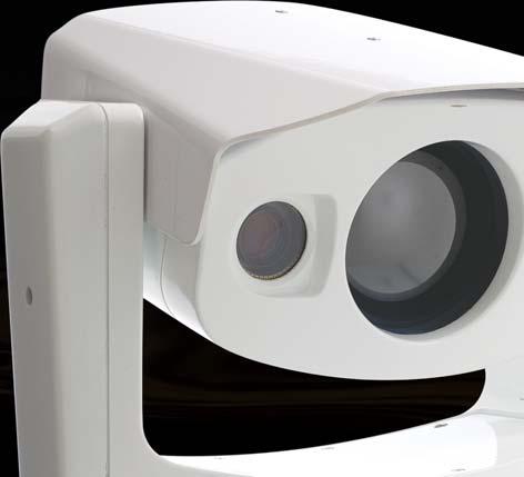
4 VOYAGER II INSTALLATION Introduction Thank you for buying your new Voyager II! This manual describes the physical mounting and electrical connection of the Voyager II camera. If you need help during the installation process, call to speak with one of FLIR s Applications experts. The Voyager II should be installed by a qualified marine electronics technician, as incorrect installation could void the warranty. The Voyager II comes with these standard components: Camera Body Bulkhead Box NMEA Interface Board (in a separate bag inside the Bulkhead Box) 50 or 100 main sensor cable (depending on what you ordered) - connects the Camera Body to the Bulkhead Box Joystick Control Unit (JCU) with 100 cable that connects to the Bulkhead Box System Power cable (10 ) Voyager Documentation Package You may need to supply: 16- gauge electrical wire; up to 100 (3-conductor, for system power) Six (6) ¼-20 stainless steel bolts for attaching the Voyager II Camera Body. Note that bolt length may be dependant on mounting platform thickness Four (4) bolts or screws for attaching the Bulkhead Box as required Miscellaneous electrical hardware, connectors and tools If using the NMEA interface features, you will need to provide a 2-wire serial cable to the Bulkhead Box from your NMEA device. Installation Preparation Find a good place to mount the Voyager II s components: o Mount the Voyager II as high as practical, but without interfering with any radar, navigational or communications electronics, and minimizing the degree to which vessel structures block the camera s view. o Mount the Voyager II as close to the vessel s centerline as possible so you will have a symmetrical view of on-coming traffic. o Voyager II should be mounted on a flat surface with the base on the bottom and the camera on top. Do not hang the Voyager II upside down; the picture will display upside down, and you may damage the Voyager II. Prior to Cutting/Drilling Holes Once the mounting location has been selected, verify both sides of the mounting surface are accessible. Determine if any interior trim panels must be removed in order to gain access to the mounting hardware, and remove them ahead of time. When selecting a mounting location for the Voyager II, consider cable lengths and routing. Ensure the cables are long enough, given the proposed mounting locations and cable routing requirements, and route the cables before you install the components. 4


.")

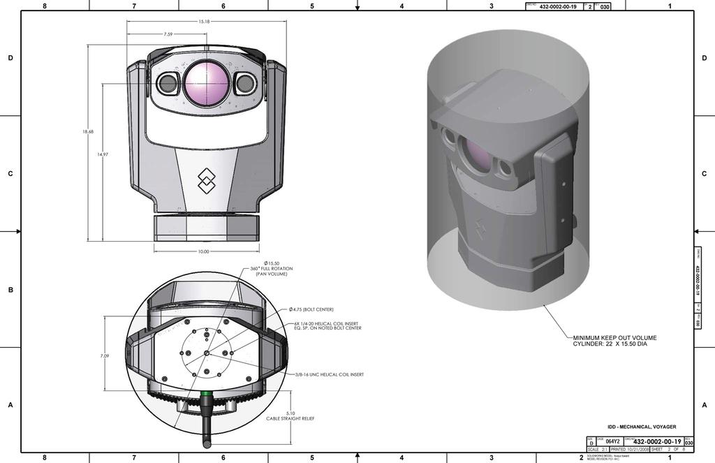
5 PHYSICAL INSTALLATION Voyager II Camera Body Using the template supplied with this Installation Manual as a guide, mark the location of the holes for mounting the Voyager II. Make sure the template is aligned so that the Voyager II will point straight ahead, and that the cable will exit towards the stern of the vessel. Mount the Voyager II s camera body with 6 1/4x20 bolts and washers. There is also a 3/8x16 center insert which can be used for added support. Voyager II Bulkhead Box NOTE: FLIR recommends that you terminate all cable ends inside the Bulkhead Box BEFORE you mount it. Refer to the section on detailed cable preparation and termination for these instructions. Mount the Bulkhead Box in an area that: Is sheltered from the weather Has good airflow Is not exposed to direct sunlight Is within easy reach of all required cables Provides room for adequate service loops as depicted in the installation drawings supplied Voyager II Joystick Control Unit (JCU) Mount the JCU in a convenient area that is close to the monitor that will display the Voyager II video output. Make sure the area you choose will leave enough room for the connector and cable under the JCU (refer to the drawing package supplied for dimensions). Using the template supplied with the Installation Manual as a guide, mark the locations of the holes to be cut and drilled for the JCU. Cut the hole that will allow the JCU to be recessed in the vessel s control console per the installation drawings supplied, and drill the holes for the four mounting studs. Route the JCU cable through the JCU munting hole. Connect the terminated end of the cable to the JCU, insert the JCU into its mounting location and secure with the supplied mounting studs. 5


6 The following sections (Electrical Interconnect and NMEA Interface) describe the connections to the Voyager. Refer to the NMEA 0183 Standard for details on interconnecting the Voyager II with other marine electronic devices. ELECTRICAL INTERCONNECT Main Sensor Cable After routing the main sensor cable between the Camera Body and the Bulkhead Box, install the Camera Body and connect the terminated end of the main sensor cable to the connector on the back of the Camera Body s base. This section describes the procedures required to prepare the main sensor cable, JCU cable and main power cable for termination inside the Bulkhead Box. The following tools and documents are recommended to complete the job: The installation drawings and templates (FLIR p/n ) at the end of this manual Ruler or measuring tape Exacto knife Scissors Wire cutter Wire stripper for 20 gauge wires Crimping tool for BNC connector Channel locks 2mm flathead screw driver Installation Steps Step 1: Remove the main sensor cable feed through grommet (A) by unscrewing it from the lock nuts (B) and (C) on the Bulkhead Box. C A B Step 2: Unscrew the grommet cap (A) from the cable gland (B) to expose the grommet seal A B 6


7 Step 3: Remove the grommet seal from the cable gland by inserting a finger and pulling it out. Step 4: Now that the grommet cap (A), seal (B), and cable gland (C) have been disassembled, remove the other sections of the grommet from the front of the Breakout Box, including the 1 reducer (D), and the inner lock nut (E). A B C D E Step 5: Now prepare the main cable ends for attachment to the inside of the Bulkhead Box. As directed by the drawing supplied in this Installation Manual, measure 13.5 from the end of the cable, carefully cut around the outer black cable jacket until you can slide it off, and remove it. Be careful not to cut into the metal braid beneath the outer jacket. Step 6: Slide the black outer jacket off the cable, exposing the inner metal braid 7


 over the cable A B C Step 10: Slide the grommet seal up")
8 Step 7: Push the braid back over the black outer jacket an inch or two, creating an area of slack in the braid. Carefully insert scissor tips into the braid, and cut all the way around it as shown. Slide the excess braid off the cable and discard it Step 8: Working with the shorter length of braid, trim it so that only 1 extends beyond the black outer jacket as shown. Step 9: Slide the grommet cap (A not shown), seal (B), and cable gland (C) over the cable A B C Step 10: Slide the grommet seal up the cable so that the front edge just lines up with the end of the black outer cable jacket as shown 8


9 Step 11: Carefully fold the metal braid back over the grommet seal as shown Step 12: Trim the metal braid as shown, so that the black o-ring seal is clear of the metal braid. Step 13: Slide the cable gland over the grommet seal as shown, capturing the metal braid between the two Step 14: Screw the grommet cap onto the cable gland as shown. You are now ready to prepare the cable ends for connection to the Bulkhead Box s internal termination blocks 9


 onto the RG-179 cable.")
10 Step 15: Trim the clear Mylar sheath back so the individual wire bundles can be spread apart as shown. This will make them easier to identify and work with. Cut the blue Ethernet cable to 12.5 long, measured from the end of the cable gland. Cut the wire bundle inside a clear jacket and steel braid to measure 11.5 long. Cut the bundle of 4 twisted pairs inside a white outer jacket to measure 11.5 long. The video cable should be cut to 9.5 Step 16: Prepare the video cable by securing the crimpable 75-ohm BNC connector (provided) onto the RG-179 cable. Step 17: The rest of the wires will need to be prepared in a fashion similar to the following progression. Carefully cut around the outer insulation as shown. 10


11 Step 18: Slide the outer insulation off, and separate the two inner wires as shown Step 19: Strip ¼ from the end of each wire as shown. When this is done, they are ready for termination in the Bulkhead Box. Step 20: Slide all of the prepared wires and the video cable through the 1 reducer. Then carefully pass all of the prepared wires and the video cable through the hole in the front of the Bulkhead Box. Step 21: Slide all of the prepared wires and the video cable through the lock nut, and secure it to the 1 reducer as shown 11
12 Step 22: Connect the wires from the main sensor cable to terminal blocks J6, J7, J8, and Video In using the drawings provided at the end of this manual for guidance. Step 23: Connect the wires from the system power cable to J5. The cable ends are prepared using the same procedures you used for everything in the main sensor cable except the video cable. Step 24: Connect the wires from the Joystick Control Unit (JCU) to the J1 terminal block. The cable ends are prepared using the same procedures used for the main sensor cable. Step 25: Install additional (optional) JCUs and other connections as required to J2 - J4, as shown on the next page. When all wires have been connected, mount the Bulkhead Box in the selected location. 12

13 J4 J8 J3 J7 J2 J6 J1 J5 13

14 NMEA INTERFACE The Voyager II has the capability to listen to (or take commands from) radar, GPS or other devices using the National Marine Electronics Association (NMEA) 0183 Protocol. The NMEA 0183 protocol is a combined electrical and data specification for communication between marine electronic devices. Additional information regarding the protocol can be found on the NMEA web site: org/pub/0183/ According to the NMEA protocol, the Voyager II is known as a listener, and another device such as a radar or multi-function display is known as a talker. This protocol allows the talker to send positional information to the Voyager II camera, and it responds by automatically pointing toward vessels and other objects that show up on the display and tracking their movement. The Voyager II connects to the other equipment via a serial cable (not provided with the Voyager II). The serial cable connects to the Voyager II through an unused Joystick Control Unit (JCU) slot on the Voyager Bulkhead Box. This document describes the steps necessary to install and verify the Voyager II NMEA 0183 interface. Operation of the Voyager II NMEA interface is described in the Voyager II User s Guide Addendum. References Voyager Installation Guide, FLIR Document Number: National Marine Electronics Association, NMEA 0183 Version 2.0 Note, the Voyager II does not support the NMEA 0183-HS (High Speed) protocol NMEA INTERFACE INSTALLATION NMEA Installation Card The Voyager II communicates with other devices through a custom interface card. The card is plugged into one of the four JCU connector slots in the Bulkhead Box. The interface card has pigtail wires to connect to the other NMEA device. Figure 1: NMEA Interface Card Connector Slot The interface card comes installed in slot J4 by default. The card must be moved to the JCU slot after the last active JCU. For a system with one JCU, the module should be plugged into the J2 slot; for systems with 2 JCUs, the module must use the J3 slot (as pictured below). For a system with 3 JCUs, the module must use slot J4. 14


15 Figure 2: Bulkhead box JCU connection with NMEA card installed in Slot 3 NMEA Interface Wiring The connection from the other NMEA device must be routed through one of the JCU cable glands located on the bottom wall of the Bulkhead Box. Figure 3: Cable Glands on the Bulkhead Box There are two methods for connecting the NMEA cable to the NMEA interface card. The first method makes use of a spare JCU slot (in the case when only one or two JCUs are used); the second method makes use of a pigtail connection when 3 JCUs are in use and the NMEA card occupies the 4th slot. Spare JCU Slot (1 or 2 JCUs in use) For a configuration that uses one or two JCUs and with the NMEA card plugged into the second or third slot, the empty adjacent slot (J3 or J4, respectively) can be used to connect NMEA signals as shown in Figure 4. 15

16 Figure 4: NMEA Interface card on Slot J3; NMEA connection in Slot J4 For this connection, attach NMEA A and B signal wires to connector terminals 1 and 2 respectively. These terminals are interconnected to the appropriate terminals in the previous slot within the Bulkhead Box. No additional jumpers are necessary. Pigtail Connection (3 JCUs in use) For a Voyager II configuration with 3 JCUs and a NMEA interface, all four JCU slots are occupied. The NMEA card will reside in the JCU slot J4. Route the NMEA interface cable up to the JCU slot J4 and, using a cable tie, anchor the NMEA cable to the 3rd JCU cable. Cutoff the shrink wrap insulator on the end of the wires and using in-line crimp splices and attach the NMEA talker signals A and B to the pigtail red and yellow wires respectively. Figure 5: NMEA Interface Card with Pigtail cable Electrical Checkout Disable the NMEA talker and verify the static RS-422 signal levels by measuring the voltage differ- 16
17 ence between the differential RS-422 outputs. The voltage should be measured on the adjacent JCU; namely, if the module is plugged into JCU J3 slot, then the measurement should be on the connector residing in the JCU J2 slot. Using a volt meter, measure the voltage difference from pin 8 (hot probe) and pin 9 (return probe of the VOM). The voltage reading should be greater than +2.0V. Pin 9 Pin 8 Figure 6: Voltage Test Points Testing the NMEA Interface Message Checkout Refer to the user manual for the other NMEA device (the talker) for information on how to install the connection and how to enable and control the NMEA messages it will generate. Enable the NMEA talker and set the Baud Rate to Use the SETUP/NMEA menu and enable RSD to allow the Voyager system to respond to the RSD message (refer to the Voyager II Operator s Manual Addendum for information on how to access the SETUP menu.) Next, get the NMEA talker to generate an RSD message. For example, using the cursor on the multifunction display unit, move the cursor and verify that the Voyager responds to the RSD message. If the talker is configured to send only the cursor message, there may be delays due to packetizing of the NMEA messages by the JCU. Under normal circumstances, a significant volume of other NMEA messages are present and this allows good packetization that results in minimal delay. 17

18 CONNECTIONS QUICK REFERENCE DRAWINGS & INSTALLATION TEMPLATES The drawings provide more detailed dimensions and mounting information. If you have any questions, call FLIR s Applications Experts at Use the templates to locate the holes required to mount the Voyager II s Camera Body and JCU. 18
19 19
20 20
21 21
22 22
23 23
24 24
25 25
26 This page intentionally left mostly blank. 26
27 Caution: When you print this document from the.pdf file, the installation templates may not be to scale. Be sure to check the dimensions prior to cutting any holes. 27
28 This page intentionally left mostly blank. 28
29 Caution: When you print this document from the.pdf file, the installation templates may not be to scale. Be sure to check the dimensions prior to cutting any holes. 29
30 This page intentionally left mostly blank. 30
31 This page intentionally left mostly blank. 31


 FX: + 1 805.685.2711 www.")


 765.")
32 FLIR Systems, Inc. CVS World Headquarters 70 Castilian Drive Goleta, CA USA PH PH: (Sales) PH: (Apps) FX: FLIR Systems, Inc. Corporate Headquarters SW Parkway Avenue Wilsonville, OR USA PH: FX: sales@flir.com CVS Eurasian Headquarters FLIR Systems CVS BV Charles Petitweg NW Teteringen - Breda The Netherlands PH: +31 (0) FX: +31 (0) flir@flir.com 32
VOYAGER II INSTALLATION GUIDE
 VOYAGER II INSTALLATION GUIDE 1 FLIR Systems, Inc., 2010. All rights reserved worldwide. No parts of this manual, in whole or in part, may be copied, photocopied, translated, or transmitted to any electronic
Navigator II INstallatIoN MaNUal For static and PaN/tIlt configurations
 Navigator II Installation MANUAL For Static and Pan/Tilt Configurations Document Number: 432-0001-00-12, rev 100 FLIR Systems, Inc., 2008. All rights reserved worldwide. No parts of this manual, in whole
Installing a Power over Ethernet injector
 Installing a Power over Ethernet injector AlphaEclipse StreetSmart and RoadStar signs The instructions in this document explain how to install/replace a Power over Ethernet (PoE) injector in a StreetSmart
Integration with NMEA Devices Application Note
 Integration with NMEA Devices Application Note MV-Series & MU-SeriesThermal Cameras This document is controlled to FLIR Technology Level 1. The information contained in this document pertains to a defense
3M Add-On Terminals 4220P (100, 200, 300 & 400 pairs)
") 3M Add-On Terminals 4220P (100, 200, 300 & 400 pairs) Instructions August 2011 3 78-8130-2330-1-C 1.0 General 1.1 The 3M Add-On Terminals 4220P-100, 4220P-200, 4220P-300 and 4220P-400 are designed to expand
3M Add-On Terminals 4220P (100, 200, 300 & 400 pairs) Instructions August 2011 3 78-8130-2330-1-C 1.0 General 1.1 The 3M Add-On Terminals 4220P-100, 4220P-200, 4220P-300 and 4220P-400 are designed to expand
Outdoor PTZ. Mounting on the Ceiling Using Pendant Mount. Installation Guide. For Models: I93, I94, I95, I96, KCM /12/03
 Outdoor PTZ Mounting on the Ceiling Using Pendant Mount For Models: I93, I94, I95, I96, KCM-8211 2013/12/03 Table of Contents Mounting Solutions... 3 Straight Tube Installation Procedures... 4 Step 1:
DirectCommand Installation RoGator Model Year Ag Leader Technology
 Note: Indented items indicate parts included in an assembly listed above Part Name/Description Part Number Quantity Direct Command Kit 4100801 1 Dual Lock 2000052-9 1 Dual Lock 2000053-9 1 Quick Reference
Rack Mount Cabinet with Fiber Mgmt System, accepts up to 3 Adapter Plates. Rack Mount Cabinet with Fiber Mgmt System, accepts up to 6 Adapter Plates
 SEPTEMBER 2009 RACK MOUNT CABINETS Be sure to read and completely understand this procedure before applying product. Be sure to select the proper Optical Cable Corporation product before application. Product
RAM Rail Mount Kit RAM 201U 5 Arm RAM 2461U Monitor Mount RAM 235U Base, Double U-Bolt
 Note: Indented items indicate parts included in an assembly listed above Part Name/Description Part Number Quantity DirectCommand Kit 4100800 1 Cable Installation Kit 2000901-1 1 Dielectric Grease 2002872
Indoor Protected Entrance Terminal 4588 Series
 Indoor Protected Entrance Terminal 4588 Series Instructions Underwriters Laboratories (UL) Listed September 2003 78-8135-1209-8-A 1.0 General The 3M Indoor Protected Entrance Terminal (PET) 4588 Series
BreezeMAX Wi² and BreezeACCESS Wi² Quick Installation Guide
 This Quick Installation Guide is intended for experienced installers. For more information refer to the relevant sections in the BreezeMAX Wi² and BreezeACCESS Wi² System Manual. Wi² Package Content Check
Mounting on the Ceiling Using Flush Mount (Face Down)
") Mounting on the Ceiling Using Flush Mount (Face Down) Installation Guide 2014/02/14 Table of Contents Safety Information... 3 Installation Procedures... 5 Step 1: Drill a Hole on the Ceiling... 5 Step
Mounting on the Ceiling Using Flush Mount (Face Down) Installation Guide 2014/02/14 Table of Contents Safety Information... 3 Installation Procedures... 5 Step 1: Drill a Hole on the Ceiling... 5 Step
MODEL 8000MP LEVEL SENSOR
 1 MODEL 8000MP LEVEL SENSOR INSTRUCTIONS FOR INSTALLATION, OPERATION & MAINTENANCE VISIT OUR WEBSITE SIGMACONTROLS.COM 2 SERIES 8000MP LEVEL SENSOR 1. DESCRIPTION The Model 8000MP Submersible Level Sensor
PowerView Model PV1000. Hardware Installation Manual Section 78
 PowerView Model PV1000 Hardware Installation Manual 00-02-0599 07-19-07 Section 78 In order to consistently bring you the highest quality, full featured products, we reserve the right to change our specifications
TABLE OF CONTENTS SECTION 1 TABLETOP CONFIGURATION SECTION 2 TABLETOP CONFIGURATION ACCESSORIES SECTION 3 SLIDE CONFIGURATION
 S6 USER S MANUAL TABLE OF CONTENTS SECTION 1 TABLETOP CONFIGURATION SECTION 2 TABLETOP CONFIGURATION ACCESSORIES SECTION 3 SLIDE CONFIGURATION SECTION 4 SLIDE CONFIGURATION ACCESSORIES SECTION 5 RACK MOUNT
Components. Tools for Setup. Installation Outline
 VANTAGE PRO AND VANTAGE PRO PLUS Fan-Aspirated ISS Retrofit Kit Installation Instructions Estimated Time Required: 60 Minutes These instructions describe how to install the Vantage Pro Fan-Aspirated Integrated
Ag Leader Technology. DirectCommand Installation Miller Nitro 5000 & 6000 ISO Kit
 Note: Indented items indicate parts included in an assembly listed above Part Name/Description Part Number Quantity Direct Command Miller N5/5000 Series Kit 4200179 1 Installation Instructions 2006382
7" Touch Screen Display
 7" Touch Screen Display Installation Guide Contents Minimum Requirements...1 Select a Location...1 Initial Setup...2 Unboxing...2 Installation...3 Prepare the Panel...3 Install the Mounting Plate...3 Mount
G12/G12x USER S MANUAL
 G12/G12x USER S MANUAL TABLE OF CONTENTS SECTION 1 SLIDE CONFIGURATION SECTION 2 SLIDE CONFIGURATION ACCESSORIES SECTION 3 TABLETOP CONFIGURATION SECTION 4 TABLETOP CONFIGURATION ACCESSORIES SECTION 5
DirectCommand Installation CASE IH SPX Ag Leader Technology. PN: Rev. E January 2014 Page 1 of 19
 Note: These installation instructions only cover installation on SPX 4420 Sprayers only. For installation on SPX 3230/3330 Sprayers refer to Installation Instructions P/N 2005945. For SPX 4430 refer to
RAM Rail Mount Kit RAM 201U 5 Arm RAM 2461U Monitor Mount RAM 235U Base, Double U-Bolt
 DirectCommand Installation Ag Leader Technology Note: Indented items indicate parts included in an assembly listed above Part Name/Description Part Number Quantity DirectCommand Kit 4100852 1 Cable Installation
M-Series Revision 130 January Installation Guide
 M-Series 432-0003-00-12 Revision 130 January 2011 Installation Guide FLIR Systems, Inc., 2010. All rights reserved worldwide. No parts of this manual, in whole or in part, may be copied, photocopied, translated,
MCH WIRE HARNESS WITH QUICK DISCONNECT REPLACEMENT Initial Release 1/31/2013
 1. Table of Contents 1. Table of Contents Page 1 2. Remove Failed MCH-103.2 Page 1 3. Install MCH-103.2 to MCH-102NW Page 2 4. Install NC3FX-HD to MCH-103.2 Page 3 5. Install MCH-103.2 Battery Terminal
Installation Guide. Retrofit Kit for USB Ready Intraoral Systems
 Installation Guide Retrofit Kit for USB Ready Intraoral Systems Table of Contents Wall-Mount Retrofit Kit... 2 Introduction... 2 Connecting the Articulating and Horizontal Arm Cables... 2 Installing the
Ag Leader Technology Insight. Direct Command Installation Spra-Coupe 7000 Series
 Note: Indented items indicate parts included in an assembly listed above. Part Name / Description Part Number Quantity Direct Command Spra-Coupe 7000 Kit 4100531 1 Liquid Product Control Module 4000394
Note: These installation instructions are only for the 4430/4440 Sprayer. For other SPX models please refer to P/N , &
 DirectCommand Installation Ag Leader Technology Note: These installation instructions are only for the 4430/4440 Sprayer. For other SPX models please refer to P/N 2005944, 2005945 & 2006383. Part Name/Description
Notice to customer Changing and calibrating lenses. Table of contents. 1 Thank you! 2 Applicability
 Copyright All rights reserved worldwide. Names and marks appearing herein are either registered trademarks or trademarks of FLIR Systems and/or its subsidiaries. All other trademarks, trade names or company
E1135C PDU and Pod Upgrade Procedure
 E4030-90010 Rev. B 12/2003 In this Document... Tools Needed, 2 Contents of the Upgrade Kits, 2 Installation Procedures, 4 Verifying the Power Option of the New PDU, 4 Removing the PDU from the Support
Ag Leader Technology. DirectCommand Installation RoGator Model Years
 Note: Indented items indicate parts included in an assembly listed above Part Name/Description Part Number Quantity Direct Command Kit 4100550 1 Dual Lock 2000052-9 1 Dual Lock 2000053-9 1 Hardware Kit
E2460GS Oscilloscope Upgrade Kit
 Installation Instructions for E2460GS Oscilloscope Upgrade Kit Agilent 1670G-Series Logic Analyzers This kit upgrades either the Agilent Technologies 1670G, Agilent 1671G, Agilent 1672G, or the Agilent
DirectCommand Installation DirectCommand Complete Wiring Harness
 Note: Indented items indicate parts included in an assembly listed above Part Name/Description Part Number With Switch Box Quantity by Model With Boom Switch Cable Display Cable Kit 4100814 1 1 Power Control
3M Indoor Protected Building Entrance Terminal 4788V-QCS Series
 The Network of Networks. 3M Indoor Protected Building Entrance Terminal 4788V-QCS Series with 3M Quick Connect System (QCS) 2811 Dry Flame Retardant Block for Field-Terminated Building Cables Instructions
Treadmill Integrated LCD Screen Option. Cardio Theater Integrated Bracket Assembly Instructions
 Treadmill Integrated LCD Screen Option Cardio Theater Integrated Bracket Assembly Instructions Table of Contents 1 2 3 4 5 6 Before You Begin... 4 Obtaining Service... 4 Unpacking the Equipment... 4 Important
Network Controller. Installation/Troubleshooting Instructions NK220 COM1131C
 Network Controller NK220 COM1131C Installation/Troubleshooting Instructions Part No. 70399101R4 October 2009 Table of Contents Getting Started... 2 Components of Network Controller... 2 System Overview...
TECHKNOW, INC. Kiosk Order Confirmation System INSTALLATION MANUAL. Revision Date: July 11, 2012 Part # Version 3.2
 document Page 1 of 18 TECHKNOW, INC Kiosk Order Confirmation System INSTALLATION MANUAL Revision Date: July 11, 2012 Part # Version 3.2 Techknow, Inc. 393 Mayfield Road Duncan, SC 29334 www.gotechknow.com
M250 (M LL) Safety
 Safety") M250 SAFETY M250 (M250-60-2LL) Safety Important Safety Information This document contains important instructions to use during installation of the Enphase M250 Microinverter. To reduce the risk of electrical
M250 SAFETY M250 (M250-60-2LL) Safety Important Safety Information This document contains important instructions to use during installation of the Enphase M250 Microinverter. To reduce the risk of electrical
FortiCam SD20 Mounting Guide
 FortiCam SD20 Mounting Guide FortiCam SD20 Mounting Guide April 14, 2016 Copyright 2016 Fortinet, Inc. All rights reserved. Fortinet, FortiGate, FortiCare and FortiGuard, and certain other marks are registered
3M Indoor Protected Building Entrance Terminal 4588V-QCS Series
 3M Indoor Protected Building Entrance Terminal 4588V-QCS Series with 3M Quick Connect System 2811 Dry Flame Retardant Block Instructions Underwriters Laboratories (UL 348X) Listed April 2010 3 78-0013-1813-4-A
Raven Adapter Harness
 Note: Indented items indicate parts included in an assembly listed above Quantity by System Part Name/Description Part Number With Switch Box With Built-in Switches Raven Harness Adapter Kit 4100504 1
Phase Loss Protection Upgrade. Phase Loss Protection Upgrade. In this bulletin:
 Phase Loss Protection Upgrade In this bulletin: Introduction... 2 Purpose... 2 General... 2 Applicability... 2 HD3070 Phase Loss Protection Upgrade Kit Parts... 2 Preparation... 4 Install the Phase Loss
M215 (M215-60) Safety
 Safety") M215 QUICK INSTALL GUIDE M215 (M215-60) Safety Important Safety Information This document contains important instructions to use during installation and maintenance of the Enphase M215 Microinverter. To
M215 QUICK INSTALL GUIDE M215 (M215-60) Safety Important Safety Information This document contains important instructions to use during installation and maintenance of the Enphase M215 Microinverter. To
FC Series Traffic Camera. Architect & Engineering Specifications
 FC Series Traffic Camera Architect & Engineering Specifications This document is controlled to FLIR Technology Level 1. The information contained in this document pertains to a dual use product controlled
1 Installing the VG4-A-ARMPLATE
 VG4 24 VAC Mounting Plate Installing the VG4-A-ARMPLATE en 1 1 Installing the VG4-A-ARMPLATE This addendum provides supplemental information for the AutoDome Modular Camera System Installation Manual.
Installation Notes TII Model 341 Protector
 Installation Notes TII Model 341 Protector (ATT-IS PEC 32918) for MERLIN Communications System In Range Out of Building (IROB) Station Installation By Trained Technician Only WARNING: Failure to follow
Enphase S-Series Microinverter and Engage Cable Safety
 SAFETY Enphase S-Series Microinverter and Engage Cable Safety Important Safety Information (S280-60-LL and S230-60-LL) This document contains important instructions to use during installation of the Enphase
SITRANS F Coriolis Flowmeters SITRANS FCT030 transmitter Quick Start
 SITRANS F Coriolis Flowmeters Quick Start Before installing, including in hazardous areas, refer to the Operating Instructions on the internet or on the SITRANS F literature CD-ROM. They contain detailed
COMPLETE S YSTEM SHELTER
 COMPLETE S YSTEM SHELTER The weather-resistant Complete System Shelter (CSS) provides protection from the elements for system components such as the console, Solar Power Kit components, sensor interface
IS-DM220/IR/HB IS-DM220
 IS-DM220/IR/HB IS-DM220 Installation Guide Indoor/Outdoor Ver. 1.2 00P6NX223ZXSEA2 Table of Contents 1. Indoor Camera Installation... 3 1.1 Hard Ceiling... 3 1.2 In-Ceiling (T-Bar) Mounting... 13 1.3 4S
Schneider Automation Modbus Plus Network Installing Clustered Node Devices Publication: 890 USE Rev. 1.0 Part Number:
 Schneider Automation Modbus Plus Network Installing Clustered Node Devices Publication: 890 USE 53 00 Rev..0 Part Number: 3000939 Modbus Plus devices must be installed as specified in a network layout
Assembly Instructions
 Assembly Instructions Flat Screen Garage End User & IT Computer Cable Management May 2013 nylon zip-tie #2 (for computer wires) rear-access beam door (open) Figure 1 nylon zip-tie #1 (for #1 motor control
How to build an Olympus D-360L Trail Camera using the PixController Universal "Digital Trail Camera Kit" w/ RS-232-U PIC Chip
 Copyright, PixController, Inc. http://www.pixcontroller.com, all rights reserved. How to build an Olympus D-360L Trail Camera using the PixController Universal "Digital Trail Camera Kit" w/ RS-232-U PIC
Cycles Integrated LCD Screen Option. Cardio Theater Integrated Bracket Assembly Instructions
 Recumbent Upright Cycles Integrated LCD Screen Option Cardio Theater Integrated Bracket Assembly Instructions Table of Contents 1 2 3 4 5 6 7 Before You Begin... 4 Obtaining Service... 4 Unpacking the
ABB DRIVES UK gland plate (+H358) ACS880-11, ACS880-31, ACH580-31, ACQ Installation guide
 ACS880-11, ACS880-31, ACH580-31, ACQ Installation guide") ABB DRIVES UK gland plate (+H358) ACS880-11, ACS880-31, ACH580-31, ACQ580-31 Installation guide Installation guide UK gland plate (+H358) ACS880-11, ACS880-31, ACH580-31, ACQ580-31 Table of contents 2018
ABB DRIVES UK gland plate (+H358) ACS880-11, ACS880-31, ACH580-31, ACQ580-31 Installation guide Installation guide UK gland plate (+H358) ACS880-11, ACS880-31, ACH580-31, ACQ580-31 Table of contents 2018
Terminals, Lugs, and Fasteners
 Terminals, Lugs, and Fasteners East Penn cast terminals are manufactured with 100% recycled lead. Lead is recognized as the premium choice in battery cable terminals because of its maximum current carrying
TruVision IP PTZ Camera Installation Guide
 TruVision IP PTZ Camera Installation Guide P/N 1072666A-EN REV 1.0 ISS 24SEP13 Copyright 2013 UTC Fire & Security Americas Corporation, Inc. Interlogix is part of UTC Climate Controls & Security, a unit
Replacing the PanelMate Power Pro 1785 Series, PanelMate epro 7585x-8 and 7685x-8 Series Backlight Assembly
 Replacing the PanelMate Power Pro 1785 Series, PanelMate epro 7585x-8 and 7685x-8 Series Assembly Introduction The Replacement Kit provides a replacement backlight for the PanelMate Power Pro 1785 Series,
LARGE S URGE-PROTECTOR S HELTER
 LARGE S URGE-PROTECTOR S HELTER The weather-resistant Large Surge-Protector Shelter (simply referred to as the shelter in this manual) provides protection from the elements for Surge Protectors (not included)
SUN KTL-M0 Quick Guide (Europe Edition) Issue: 01 Part Number: Date: HUAWEI TECHNOLOGIES CO., LTD.
 Issue: 01 Part Number: Date: HUAWEI TECHNOLOGIES CO., LTD.") SUN2000-60KTL-M0 Quick Guide (Europe Edition) Issue: 01 Part Number: 91509499 Date: 2018-02-10 HUAWEI TECHNOLOGIES CO., LTD. NOTICE The information in this document is subject to change without notice.
SUN2000-60KTL-M0 Quick Guide (Europe Edition) Issue: 01 Part Number: 91509499 Date: 2018-02-10 HUAWEI TECHNOLOGIES CO., LTD. NOTICE The information in this document is subject to change without notice.
A-dec 570L Dental Light on a DCS System INSTALLATION GUIDE
 A-dec 570L Dental Light on a DCS System INSTALLATION GUIDE C ONTENTS Choose an Installation Guide...... Before You Begin.............. 3 Disconnect the Light Cable........ 3 Cut the Light Cable............
V910 Kit. Hardware Installation Guide. P/N Revision: A
 V910 Kit Hardware Installation Guide P/N 28935 Revision: A V910 Kit Hardware Installation Guide VeriFone, Inc. 2099 Gateway Place Suite 600 San Jose, CA 95110 Telephone: 408-232-7800 http://www.verifone.com
DirectCommand Installation 5 Channel Spreader Control Module Technology
 DirectCommand Installation Ag Leader Technology Note: Indented items indicate parts included in an assembly listed above Part Name/Description Part Number Quantity Direct Command Kit 4100582 1 Cable Installation
A Axis M-Functions Level 1 A Axis Standard A Axis SMT Level 2. Each console includes the following:
 Hardware List The 3000M Crusader II Upgrade system has been custom configured to provide the necessary hardware required for installation on your machine. Verify that you have received all the correct
2 PIECE BOARD-TO-BOARD
 2 PIECE BOARD-TO-BOARD 201-01-123 1. SPECIFICATION DISTRIBUTION No restrictions for issue 2. SCOPE This specification contains the application notes for the 9159 two part connectors. 3. PRODUCTS 10-9159
DIGITAL OBSERVATION GUARD LOW PROFILE PAN TILT KIT USER MANUAL
 DIGITAL OBSERVATION GUARD LOW PROFILE PAN TILT KIT USER MANUAL Version 2.1 June 4, 2013 0 Table of Contents Low Profile Pan Tilt Kit Description... 3 Low Profile Pan Tilt Unit Basic Operation... 4 Mounting
Agilent N2916B 6000 and 5000 Series Oscilloscope Rack Mount Kit
 Agilent N2916B 6000 and 5000 Series Oscilloscope Rack Mount Kit Installation Guide Agilent Technologies Notices Agilent Technologies, Inc. 2005, 2007 No part of this manual may be reproduced in any form
CONEC Industrial Ethernet Circular Sealed RJ45 Connector System consists of a RJ45 Plug Kit, a Receptacle Kit and a Protective Cover Assembly.
 Revised Sept-28-2009 Sealed Industrial Ethernet Circular IP67 Cat. 5e RJ45 Connector System Instructions CONEC Industrial Ethernet Circular Sealed RJ45 Connector System consists of a RJ45 Plug Kit, a Kit
Document revision: A
 Document revision: A Important Notice Copyright 2017 WatchGuard, Inc. All rights reserved. This document and supporting data are the exclusive property of WatchGuard, Inc. and may not be copied and/or
LED. Sign Module. Assembly Manual
 LED Sign Module Assembly Manual 6/14/2002 3:10 PM 6 2 3 3 E. S a w g ra s s R d S a ra s o ta, F L. 3 4 2 4 0 (9 4 1 )3 7 7-5 7 7 5 F A X(9 4 1 )3 7 8-4 2 2 6 www.acscontrol.com Table of Contents Table
Constructing a Low-Cost Mobile Eye Tracker
 ==== Constructing a Low-Cost Mobile Eye Tracker ==== Section 1: Introduction This is a detailed set of instructions on how to build a low-cost mobile eye-tracking system from off-the-shelf components.
In-Sight 7000 Series Vision System. Optional Configurations
 In-Sight 7000 Series Vision System Optional Configurations Legal Notices The software described in this document is furnished under license, and may be used or copied only in accordance with the terms
XCU Fusion. 316L stainless-steel dual imager camera. Installation Manual
 XCU Fusion 316L stainless-steel dual imager camera Installation Manual Note: To ensure proper operation, please read this manual thoroughly before using the product and retain the information for future
MBE Mounts and Adapters
 MBE Mounts and Adapters MBE Series en Installation Guide MBE Mounts and Adapters Table of Contents en 3 Table of Contents 1 Important safety instructions 4 2 MBE Series Mounts and Adapters 6 2.1 Unpacking
Quick Configuration Guide
 United VMS 7.0 Quick Configuration Guide Meridian 1.0 i 2016 FLIR Systems, Inc. All rights reserved worldwide. No parts of this manual, in whole or in part, may be copied, photocopied, translated, or transmitted
COOPER POWER SERIES. RS-485 digital communications accessory board installation and operation instructions. Voltage Regulators MN225074EN
 Voltage Regulators MN225074EN Effective March 2017 Supersedes January 2012 (S225-40-7) RS-485 digital communications accessory board installation and operation instructions COOPER POWER SERIES DISCLAIMER
Ariel Gen II Release Notes. Firmware Version
 Ariel Gen II Release Notes Firmware Version 20190130 Ver. 1 March 11, 2019 2018 FLIR Systems, Inc. All rights reserved worldwide. No parts of this document, in whole or in part, may be copied, photocopied,
Warning Before Installation
 Warning Before Installation English Power off the Network Camera as soon as smoke or unusual odors are detected. Refer to your user's manual for the operating temperature. Contact your distributor in the
Warning Before Installation. Package Contents EN - 1. Refer to your user's manual for the operating temperature.
 510000221G Warning Before Installation English Power off the Network Camera as soon as smoke or unusual odors are detected. Do not place the Network Camera on unsteady surfaces. Do not insert sharp or
TOPJOB S Sensor/Actuator Terminal Blocks with Push-in CAGE CLAMP Reliability
 TOPJOB S Sensor/Actuator Terminal Blocks with Push-in CAGE CLAMP Reliability TOPJOB S SEND THE RIGHT SIGNALS. TOPJOB S Sensor/Actuator Terminal Blocks with Push-in CAGE CLAMP Reliability TWO IN ONE. WITH
Part Name/Description Part Number Quantity
 Note: Indented items indicate parts included in an assembly listed above Part Name/Description Part Number Quantity Liquid Manure, Pinch Valve Kit 4200139 1 GEN 2 Large Module Mounting Kit 2001370 1 Deutsch
C764i Integrated LCD Screen Option. Cardio Theater Integrated Bracket Assembly Instructions
 C764i Integrated LCD Screen Option Cardio Theater Integrated Bracket Assembly Instructions Table of Contents 1 2 3 4 5 6 7 Before You Begin... 3 Obtaining Service... 3 Unpacking the Equipment... 3 Important
M215 Safety (M LL-S22-IG / S23-IG / S24-IG)
") M215 SAFETY M215 Safety (M215-60-2LL-S22-IG / S23-IG / S24-IG) Important Safety Information This document contains important instructions to use during installation of the Enphase M215 Microinverter. To
M215 SAFETY M215 Safety (M215-60-2LL-S22-IG / S23-IG / S24-IG) Important Safety Information This document contains important instructions to use during installation of the Enphase M215 Microinverter. To
Installation Guide V290 (Color) This guide provides basic information for Unitronics LCD color touchscreen models V C30B and V T40B.
 This guide provides basic information for Unitronics LCD color touchscreen models V C30B and V T40B.") Vision OPLC Installation Guide V290 (Color) This guide provides basic information for Unitronics LCD color touchscreen models V290-19-C30B and V290-19-T40B. General Description Vision OPLCs are programmable
Vision OPLC Installation Guide V290 (Color) This guide provides basic information for Unitronics LCD color touchscreen models V290-19-C30B and V290-19-T40B. General Description Vision OPLCs are programmable
HOW TO REPLACE A PARKER INVERTER DRIVE WITH A YASKAWA V1000 INVERTER DRIVE
 HOW TO REPLACE A PARKER INVERTER DRIVE WITH A YASKAWA V1000 INVERTER DRIVE Important: Please read this document in its entirety before removing the Parker VFD drive and installing the Yaskawa V1000 drive.
JR3 EXTERNAL SENSOR ELECTRONICS WITH ANALOG OUTPUT. JR3, Inc. 22 Harter Ave. Woodland, CA 95776
 JR3 EXTERNAL SENSOR ELECTRONICS WITH ANALOG OUTPUT JR3, Inc. 22 Harter Ave. Woodland, CA 95776 5962C 15 December, 2003 TABLE OF CONTENTS CHAPTER 1 OVERVIEW General...1-1 Sensor...1-1 Electronic System...1-1
Operating Instructions
 Operating Instructions Model Numbers: LS LS M LS G LS A LS LS 00 LS M-WC LS A LS X LS M-WC LS B LS X LS M LS Dimensions A / B / C / D / E 0 / F / Electrical Information Voltage AMPS Frequency 0 HZ Single
Verizon Wiring Manual PowerShift. 10 January 2018
 Verizon Wiring Manual PowerShift 10 January 2018 1. General DISCLAIMER: This document has been developed by CommScope, and is intended for the use of its customers and customer support personnel. The information
Installation Manual. Table of Contents
 Table of Contents Table of Contents... 4-1 4.1 Confirming the Installation Preparations... 4-1 4.2 Installation Flowchart... 4-1 4.3 Mounting the Switch to the Designated Position... 4-2 4.3.1 Mounting
Motion LE1700 Tablet PC Hard Disk Drive Upgrade Procedure
 Motion LE1700 Tablet PC Hard Disk Drive Upgrade Procedure 2008 Motion Computing, Inc. All rights reserved. This document contains information protected by copyright. No part of this document may be reproduced
Quasar Gen III CP-6302 Release Notes. Firmware Version fs nrs
 Quasar Gen III CP-6302 Release Notes Firmware Version fs20190114nrs Ver. 1 March 11, 2019 2018 FLIR Systems, Inc. All rights reserved worldwide. No parts of this document, in whole or in part, may be copied,
TruVision IP Thermal Camera Installation Guide
 TruVision IP Thermal Camera Installation Guide P/N 1073335-EN REV B ISS 19OCT17 Copyright Trademarks and patents Manufacturer Certification 2017 United Technologies Corporation, Interlogix is part of UTC
View Wall Interface. Dynamic Glass INSTALLATION GUIDE. Description. System Requirements. Installation Overview
 Description The solution is a compact, wall-mounted interface used for monitoring and changing the tint levels of View Dynamic Glass. The product leverages 802.11-based Wi-Fi technology for connectivity
AB-2D AB-2D SPEAKER A,B OR A+B SELECTOR INSTALLATION & OPERATION GUIDE
 M O D E L AB-2D AB-2D SPEAKER A,B OR A+B SELECTOR INSTALLATION & OPERATION GUIDE AB-2D Speaker/Amplifier Selector TABLE OF CONTENTS Introduction 1 Features and Benefits 1 Installation Considerations 3
MCG Surge Protection
 299-700-33B 299-700-33A MCG Surge Protection Installation/Operating Instructions for MCG 500 Series Important Warranty Information MCG surge protectors are designed to work at specific voltages and configurations,
EK27. Evaluation Kit APPLICABLE PARTS (SOLD SEPARATELY) INTRODUCTION PA50 PA52
 INTRODUCTION PA50 PA52") APPLICABLE PARTS (SOLD SEPARATELY) PA50 PA52 INTRODUCTION Evaluation Kit This easy to use kit provides a platform with good circuit board layout and grounding to evaluate linear power amplifier circuits
APPLICABLE PARTS (SOLD SEPARATELY) PA50 PA52 INTRODUCTION Evaluation Kit This easy to use kit provides a platform with good circuit board layout and grounding to evaluate linear power amplifier circuits
AI-102. IR Illuminator. Installation Guide. Rev IP Surveillance
 AI-102 IR Illuminator Installation Guide Rev. 1.1 IP Surveillance Revision History: Rev. 1.0: Initial release Rev. 1.1: Changed effective IR range and power consumption. AI-102 Tube Type Infrared Illuminator
Flat Panel Static Wall Mount MSP-SS (GSM-210)
") INSTALLATION INSTRUCTIONS Flat Panel Static Wall Mount (GSM-2) The static wall mount fits most 23 to 30 displays. The mount was designed to adapt to the VESA 75mm/0mm, 0mm/0mm, and 200mm/0mm compliant
INSTALLATION INSTRUCTIONS Flat Panel Static Wall Mount (GSM-2) The static wall mount fits most 23 to 30 displays. The mount was designed to adapt to the VESA 75mm/0mm, 0mm/0mm, and 200mm/0mm compliant
Zodiac FR100 TM INSTALLATION MANUAL
 Zodiac FR100 TM INSTALLATION MANUAL June 2014 Table of Contents INTRODUCTION... 3 SPECIFICATIONS... 4 Diodes... 5 Terminal Strips and Cable... 5 READER LAYOUT... 6 READER INSTALLATION... 7 Mounting Plate...
Installation and User Guide
 Installation and User Guide VADDIO DOMEVIEW HD INDOOR PENDANT MOUNT DOME ENCLOSURE FOR THE VADDIO HD-20, HD-19 AND HD-18 PTZ CAMERAS Part Number: 998-9100-200 2011 Vaddio - All Rights Reserved DomeVIEW
Quick Installation Guide
 FD8372 Fixed Dome Network Camera Quick Installation Guide English 繁中簡中日本語 Français Español Deutsch Português Italiano Türkçe Polski Русский Česky Svenska 5MP Full HD Smart Focus System Warning Before Installation
Ag Leader Technology. DirectCommand Installation Rogator 900/1100/1300 Sprayers
 DirectCommand Installation Ag Leader Technology Note: Indented items indicate parts included in an assembly listed above Part Name/Description Part Number Quantity DirectCommand Kit 4100876 1 Quick Reference