MS Protocol Converter. User Manual. Firmware version 2.0 ISI. Instrumental Solutions, Inc.
|
|
|
- Janice Rich
- 5 years ago
- Views:
Transcription

1 MS Protocol Converter User Manual Firmware version 2.0 ISI Instrumental Solutions, Inc.
2 Introduction The MS protocol converter can take readings from 1 or more ModBus registers on up to 2 ModBus instruments using an RS485 or RS232 interface, and make that data available on a SDI-12 network. It is preconfigured to read the Level, Velocity, Flow, Volume and Temperature registers on an Isco 2150 Area Velocity Flow Module. For special situations, the unit can be reconfigured via the text-based user interface using most any terminal software. Getting Started All wiring connections are made inside the weatherproof enclosure, with the wires passing through the waterproof fitting on the rear panel of the enclosure. Remove the rear panel by removing the 4 retaining screws and slide the circuit board out to gain access to the connectors (see Figure 1). For testing purposes, the 2150 can be plugged directly in to the DB9P connector labeled RS-232 using Isco s Serial Communication cable (Isco Part # , not included). However, permanent installations should use screw terminals 4-6 labeled GND, 232 TX, and 232 RX, respectively. See Tables 1 & 2 for more information on making electrical connections. The DB9P connector is also used for configuring the MS A nullmodem serial cable and terminal program (such as Hyperterm) is required to do this. When configuring the MS1-2150, the Isco 2150 must be disconnected from the converter. The MS is preconfigured to operate with the Isco 2150, and configuration is not normally required. The converter has 2 multi-color LED indicators on the front panel for indicating SDI-12 and Modbus data activity. The indicators light up green when the converter is receiving data on the associated interface, and red when the converter is sending data on the interface. These can be used to help diagnose communication problems.
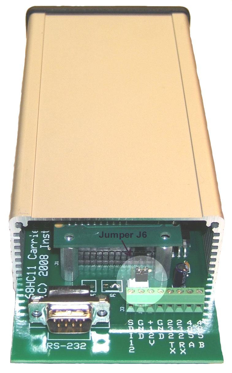
3 Figure 1
4 Table 1 - DB9P Connections Pin 1 No connection Pin 2 Receive data RS232 input Pin 3 Transmit data RS232 output Pin 4 DTR internally tied to pin 6 for flow control loopback Pin 5 Signal ground Pin 6 DSR internally tied to pin 4 for flow control loopback Pin 7 RTS internally tied to pin 8 for flow control loopback Pin 8 CTS internally tied to pin 7 for flow control loopback Pin 9 No connection Table 2 Terminal Connections #1 SDI-12 data line #2 SDI-12 ground #3 +12VDC input #4 Ground #5 Transmit data RS232 output #6 Receive data RS232 input #7 RS485 line A #8 RS485 line B Table 3 Jumper J6 Jumper installed on 1 & 2 Enable RS-232 operation Jumper installed on 2 & 3 Enable RS-485 operation Default Configuration To view the current configuration or configure the MS1-2150, make sure that the jumper on header J6 (which is located immediately behind the screw-terminal block) is in position 1-2. This is the normal position (RS-232 enabled) when using the MS with an Isco Position 2-3 is used when connecting to a device with a RS-485 interface. Please refer to Table 3 above and the highlighted portion in Figure 1, where the jumper is shown in position 2-3 (RS-485 enabled).

5 Next, disconnect any wires that are connected to the RS-232 screw terminals, then plug one end of a null-modem cable into the DB9P connector on the converter, and the other end into an available serial port on a PC. Terminal software should be set for 9600 baud, 8 data bits, no parity, and no flow control. To enter configuration mode, quickly type 3 question-mark characters. The MS should respond with the following screen: NOTE: If the converter fails to respond, try again, typing as quickly as you can. If still no response, remove and re-apply power to the converter while watching the front panel LEDs. Both LEDs should immediately light up red, then turn green after about half a second, then go out after another halfsecond. If this doesn t happen, check the power wiring for proper voltage and polarity. The MS operates on 9-14 volts DC. If the LEDs don t light when power is applied, there is a problem with the converter. If the LEDs light but there is still no response after typing question marks, make sure that you are using a null-modem serial cable, which crosses pins 2 & 3 between ends. If the unit fails to respond, there may be a problem with the converter.
6 The default configuration returns fields to the SDI-12 master in the following order: Level, Velocity, Flow, Volume, and Temperature. To change a configuration setting, type the number of the setting followed by the Enter key. The configuration mode has an inactivity timeout of 1 minute. If at any point during configuration the user goes 1 minute without typing anything, the converter automatically returns to normal online operation. Setting changes are saved as they are entered, so any changes completed during the configuration session will not be lost if a inactivity timeout occurs. The following section describes each setting in detail. 1. Modbus operations 1-12 Upon receiving a measurement request from the SDI-12 master, the MS executes a series of Modbus operations, as defined by these settings. An operation can be 1 of 3 types: a Read type (which reads a Modbus register on the attached sensor), a Write type (which writes a Modbus register on the attached sensor), or a Test type (which repeatedly reads a Modbus register on the attached sensor until the value read matches a test value specified in the operation). For example, to initiate a data sample on the Isco 2150, Modbus register number 25 must be written to a 1, which tells the 2150 to take a sample. Operation #1 accomplishes this: 1. Modbus operation 1 [*] [W] [1] Take-reading flag,set The [*] indicates that this particular operation is enabled. A disabled operation appears as [ ]. The [W] indicates that this is a Write operation. The [1] indicates that this operation uses virtual device 1. Virtual devices are discussed in the Virtual Devices section below. The Take-reading flag,set text is a plain-text description of what the operation does. To view or modify the details of a Modbus operation, type its menuselection number and hit Enter. For example, to view/modify operation #1 (menu selection 1), type 1 and hit Enter. You will be led through the following dialog:
7 1. Modbus operation 1 Enabled: Yes (Spacebar to change, Enter to accept) The spacebar will toggle this setting between Yes and No. Press the ENTER key to accept the setting and take you to the next step: [Modbus register] Current setting: 25 New setting: Enter a new value for the Modbus register, or hit Enter with no entry to keep the current setting. In this case, we are operating on register 25, which is the take-reading flag register in the Isco Data type: 16-bit signed integer (Spacebar to change, Enter to accept) The spacebar steps through all of the data types supported by the MS This setting must agree with the data type of the Modbus register being referenced. In this case, register number 25 in the Isco 2150 has a data type of 16-bit integer. Press the ENTER key to accept the setting and take you to the next step: Type of operation: Write (Spacebar to change, Enter to accept) The spacebar steps through the available types for this operation. In this case, we want to Write to the specified register on the Isco [Operation data] Current setting: 1 New setting: Enter the data value to write to the Modbus register. In this case, we write a 1 to initiate a sample on the Isco [Operation name] Current setting: Take-reading flag,set New setting: This is a free-form text description of what the operation does. Hit Enter with no entry to keep the current setting. The final setting for a Modbus operation is to select the virtual device that the operation will use. The default configuration has 1 virtual device
8 defined, Isco If there is more than one virtual device defined, the spacebar is used to select the device to use. In this case, we want to use the device named Isco 2150 : Virtual device: Isco 2150 accept) (Spacebar to change, Enter to So, Operation #1 initiates a data sample on the What happens now? Operation #2 executes next. This is a Test type of operation that causes the MS to wait for the 2150 to make sample data available. It does this by repeatedly reading Modbus register 25 on the 2150 and looking for it to change from 1 (the value that was written to it by Operation #1) to 0, which indicates that data is ready to be read. This operation will wait up to half the SDI-12 data-ready time (defined in the virtual device) for the test condition to become true. After the Test operation finishes (whether due to the test condition becoming true or a timeout occurring), the converter continues with Operations 3 7, which are all Read-type operations. Each operation reads a data field from the 2150, and returns them all to the SDI-12 master. Virtual Devices The MS can support up to 2 SDI-12 addresses on the SDI-12 network, and 2 addresses on the Modbus network. A virtual device must exist for each Modbus address to be used. The virtual device defines operating characteristics such as the SDI-12 and Modbus addresses, Modbus mode (ASCII/RTU), the Modbus function code used to read a register, and the SDI-12 timeout value. Basically, the virtual device controls the mapping of SDI-12 requests (based on the SDI-12 address specified by the master) to Modbus addresses. The MS can answer to up to 2 SDI-12 addresses, and map these to up to 2 Modbus addresses. The default configuration for the MS is one Virtual device that uses SDI-12 address 0, Modbus address 2, Modbus ASCII mode, and a read function code of 3. This configuration is required to work properly with the Isco Another typical configuration is to set Virtual device 1 with SDI-12 address 0 and Modbus address 0, and Virtual device 2 with SDI-12 address 1 and Modbus address 1. When the SDI-12 master requests a measurement from SDI-12 address 0, the MS will answer it and execute only the Modbus operations that are set to use Virtual device 1,
9 and the operations will be directed to Modbus device address 0. Likewise, SDI-12 requests directed to SDI-12 address 1 will also be answered, and only the Modbus operations that use Virtual device 2 will be executed, using Modbus address 1. The result is 2 individual data channels that have no interaction with each other. Another possibility is to set the SDI-12 address the same in both virtual devices. In this case, the MS will answer only to that address, but will execute all of Modbus operations (assuming they are enabled), even if more than one Modbus device address is defined. The MS will then combine the data from both Modbus devices into a single SDI-12 response. This is particularly useful with Isco s stackable devices, where each device on the stack is automatically assigned a unique Modbus address. 13. Virtual device Virtual device 2 These options allow you to view and configure the virtual devices. The following section describes each setting: 1. Virtual device name This is the name that the user wants to assign to the virtual device. The name shows up in the list of available devices when configuring a Modbus operation. 2. SDI12 address This is the address that the MS will answer to on the SDI-12 network. The default value is 0. This value must match the address that the SDI-12 master uses when attempting to communicate with the MS If the SDI-12 master has the ability to scan the network for sensors, this is the address that will be associated with MS on the SDI-12 master. 3. SDI12 data-ready time This is the maximum length of time in seconds that the Modbus device should take to have data available after a measurement request. The default value is 90. The MS reports this value back to the SDI-12 master in response to a measurement request. The SDI-12 master must wait this length of time before requesting data from the MS However, if the SDI-12 master issues a non-concurrent measurement request (recommended), the MS will issue a Service Request to
10 the SDI-12 master as soon as data is available from the Modbus device. This causes the SDI-12 master to immediately issue a data retrieval request, even if the data-ready time has not been reached. This can significantly speed up the data retrieval cycle. For more information concerning the SDI-12 protocol, see 4. Modbus address This is the address that the MS will send Modbus requests to on the RS232 interface. The default value is 2. To ensure proper operation with the Isco 2150, this value should not be changed. 5. Modbus mode This sets the Modbus operating mode. The choices are ASCII and RTU. Modbus ASCII is required for use with the Isco Modbus read function This sets the function code that will be sent to the Modbus device to read the data holding registers. This must be set to 3 for the Isco Restore default settings This selection resets all configuration parameters to the factory-default settings. 16. Resume normal operation This selection exits configuration mode and returns the converter to online operation. Configuration mode has an inactivity timeout of 1 minute; if at any time after entering configuration mode no characters are typed for 1 minute, the converter will automatically return to normal online operation. If this occurs in the middle of configuring a Modbus operation, no changes will be made to the configuration. Modbus operation changes are not saved until the user has stepped through all of the settings for the operation. SDI-12 Commands The MS is compliant with version 1.3 of the SDI-12 specification, which is the most recent version as of the firmware v2.0 release date.
11 The following SDI-12 commands are supported: Name Command Comment Acknowledge Active a! Send Identification ai! See SDI-12 spec for response format. Change Address aab! Does not change device configuration. Address Query?! Returns the address in the first Virtual Device or the address for the last command that was responded to. Start Measurement am! May result in a service request. Start Measurement w/crc amc! May result in a service request. Send Data ad0! ad9! Additional Measurements am1! am9! May result in a service request. Additional Measurements amc1! May result in a service request. w/crc amc9! Start Verification av! The next Send Data command will return MS status information in the format of 4 integer values. These values represent the number of invalid SDI-12 commands received, the number of Modbus CRC errors, the number of Modbus read timeouts, and the number of timeouts that have occurred during a Modbus Test operation. Start Concurrent ac! Measurement Start Concurrent acc! Measurement w/crc Additional Concurrent ac1! ac9! Measurements Additional Concurrent Measurements w/crc acc1! acc9! Continuous Measurements ar0! ar9! Not applicable with MS a<cr><lf> always returned, where a is the SDI-12 address. Continuous Measurements w/crc arc0! arc9! Not applicable with MS a<cr><lf> always returned, where a is the SDI-12 address.
12 Specifications SDI-12 interface: Modbus interface: Text interface: Operating system: Indicators: Connections: Temperature range: Power requirements: Enclosure: External dimensions: Weight: SDI-12 v1.3 compliant Modbus ASCII or RTU, RS232 or RS485, 9600 baud, 8-bit, no parity 9600 baud, 8-bit, no parity, no handshake Instrumental Solutions ISOS-11 2 bicolor LEDs for transmit/receive indication Internal screw terminals, DB9 male (DTE) -40 C to +85 C 12VDC 35ma idle, 35 ma avg, 55ma max Extruded aluminum, IP65 rated 7.52 (19.1cm) L, 3.48 (8.84cm) W, 1.85 (4.7cm) H 15 ounces SDI-12 Verification Report The MS has been verified with the NR Systems SDI-12 verifier and has passed all tests in the comprehensive sensor test suite. The results are available at:
ICD105A 1008 page 1/ r001 ICD105A. Industrial RS-232 to RS-422/485 Converter
 ICD105A 1008 page 1/5 7319 r001 ICD105A Industrial RS-232 to RS-422/485 Converter Data Rates up to 115.2 Kbps 10 48 VDC Input Power Range Wide Operating Temperature 3-Way 2000V Optical Isolation Modbus
Document Name: User Manual for SC10MK, Modbus RTU to Modbus TCP Converter
 Document Name: User Manual for SC10MK, Modbus RTU to Modbus TCP Converter Login for the first time, please use http://192.168.1.100 To key in user name and password is for identifying authorization. Default
AquiStar TempHion (SDI-12 & Modbus )
") Table of Contents Table of Contents... 1 Specifications... 1 SDI-12 Command Nomenclature... 1 SDI-12 Commands... 2 Setup Commands... 2 Measurement Commands... 2 Request Measurement... 2 Request Measurement
Table of Contents Table of Contents... 1 Specifications... 1 SDI-12 Command Nomenclature... 1 SDI-12 Commands... 2 Setup Commands... 2 Measurement Commands... 2 Request Measurement... 2 Request Measurement
EtherSeries Modbus Gateway EMB-2 User s Guide
 EtherSeries Modbus Gateway EMB-2 User s Guide Revised March 25, 2004 Firmware Version 1.4 FCC Statement This device complies with the limits for a Class B digital device, pursuant to Part 15 of the FCC
Select a Data Communication Interface
 Printer Setup and Operation Select a Data Communication Interface Select a Data Communication Interface You may connect your print engine to a computer using one or more of the available connections. The
Intelligent Devices IDI 1100 Series Technical Manual
 Intelligent Devices IDI 1100 Series 4411 Suwanee Dam Road, Suite 510 Suwanee, GA 30024 T: (770) 831-3370 support@intelligentdevicesinc.com Copyright 2011, Intelligent Devices, Inc. All Rights Reserved
AquiStar TempHion (SDI-12 & Modbus )
") Table of Contents Table of Contents... 1 Specifications... 1 SDI-12 Command Nomenclature... 1 SDI-12 Commands... 2 Setup Commands... 2 Measurement Commands... 2 Request Measurement... 2 Request Measurement
Table of Contents Table of Contents... 1 Specifications... 1 SDI-12 Command Nomenclature... 1 SDI-12 Commands... 2 Setup Commands... 2 Measurement Commands... 2 Request Measurement... 2 Request Measurement
SDI-12 Interface Cable. April 10, Built for:
 SDI-12 Interface Cable April 10, 2008 Built for: - Table of Contents 1 Introduction 3-4 1.1 Compatibility 3 1.2 SDI-12 Interface Cable 3 1.3 LED Status 4 2 Levelogger Independent Recording Option 5 2.1
Table 8 shows the pin configuration and function of a standard computer-to-printer parallel cable. Table 8 Parallel Cable Pin Configuration
 Advanced Printer Inion Parallel Data Port Parallel Data Port The parallel data interface supports IEEE 1 bidirectional parallel communications in nibble mode. The parallel interface provides a means of
Turbo Technical Bulletin
 Table of Contents Table of Contents... 1 Specifications... 1 SDI-12 Command Nomenclature... 1 SDI-12 Commands... 2 Setup Commands... 2 Measurement Commands... 2 Request Measurement... 2 Request Measurement
Operate the Hydrolab SDI-12 / Modbus / RS232 TTY Communications Module (HL Series Sonde)
") Operate the Hydrolab SDI-12 / Modbus / RS232 TTY Communications Module (HL Series Sonde) 04/2018, Edition 1 User Manual Overall Contents Part A Operate the Hydrolab SDI-12 Communications Module Part B
Operate the Hydrolab SDI-12 / Modbus / RS232 TTY Communications Module (HL Series Sonde) 04/2018, Edition 1 User Manual Overall Contents Part A Operate the Hydrolab SDI-12 Communications Module Part B
Features. Target Applications. V1.6 TBS07 RS485 to SDI-12 Converter
 The is an interface box for connecting a PC, data logger or telemetry unit to one or more sensors with SDI-12 interface. The connects to a data logger, telemetry unit or other device with RS485 interface
485DRCI. Industrial RS-232 to RS-422/485 Converter B&B ELECTRONICS PRODUCT INFORMATION. Specifications Serial Technology
 485DRCI RS-232 RS-485 2-Wrie RS-422/485 4-Wire RS-232 CON. RS-422/485 CON. Data Rate Isolation Surge Protection Industrial Bus Source Input Voltage Power Consumption Connector p/n 7207r3 485DRCI-4108ds
SDI-12 Interface Cable. August 1, Built for:
 SDI-12 Interface Cable August 1, 2017 Built for: - Table of Contents 1 Introduction 1 1.1 Compatibility 1 1.2 SDI-12 Interface Cable 1 1.3 LED Status 2 2 Levelogger Independent Recording Option 3 2.1
User Manual A08. User Manual
 A08 TABLE OF CONTENTS TABLE OF CONTENTS... 1 1. INTRODUCTION... 2 1.1. Key Features... 3 1.2. OS Requirement... 4 1.3. Specification... 4 1.4. Packing List... 4 2. OVERVIEW... 5 2.1. LED Definition...
D8000 SERIES QUICK START GUIDE
 D8000 SERIES QUICK START GUIDE Version 1.0 Overview The D8000 series modules require a DC Voltage power supply, a USB cable and an unused computer USB port for proper operation. Connecting the D8000 series
Wrenchman, Inc Old Hwy. # 8 Suite # 122 New Brighton, Minnesota (651)
") Wrenchman, Inc. 1801 Old Hwy. # 8 Suite # 122 New Brighton, Minnesota 55112 (651) 638-9012 468X Interface Cable Specifications The Interface Cable emulates the Async RS-232 logical interface supported
Wrenchman, Inc. 1801 Old Hwy. # 8 Suite # 122 New Brighton, Minnesota 55112 (651) 638-9012 468X Interface Cable Specifications The Interface Cable emulates the Async RS-232 logical interface supported
Serial Interfaces Part 1. ECE 153B Sensor & Peripheral Interface Design Winter 2016
 Serial Interfaces Part 1 ECE 153B Sensor & Peripheral Interface Design Serial Interfaces Simple Serial Interfaces RS-232C (UART) Provides for point to point communications, primarily Among the simplest
ICP PANEL-TEC PEX3000 II
 ICP PANEL-TEC PEX3000 II MODBUS PORT EXPANDER INSTALLATION AND OPERATION GUIDE REVISION HISTORY Revision Date Author Comments 000 29 Aug 2008 Keira Majors Initial release. 001 16 Sep 2008 David Walker
User's Manual PLC09 Modbus Converter for PAL-AT Leak Detection System
 User's Manual PLC09 Modbus Converter for PAL-AT Leak Detection System PermAlert ESP, Inc. 7720 Lehigh Ave. Niles, IL 60714 847-966-2190 2 INDEX 1.0 Introduction 4 1.1 Features 4 2.0 Installation 4 2.1
SIOX-RS232C Converter
 L40 SIOX-RS232C Converter p 2 TELEFRANG AB TABLE OF CONTENTS SIOX-RS232C Converter General Description This module connects a CRT terminal or other RS232C serially communicating I/O device as a station
CDN502 HIGH DENSITY I/O ADAPTER USER GUIDE
 CDN502 HIGH DENSITY I/O ADAPTER USER GUIDE 13050201 (c) Copyright DIP Inc., 1996 DIP Inc. P.O. Box 9550 MORENO VALLEY, CA 92303 714-924-1730 CONTENTS DN502 PRODUCT OVERVIEW 1 DN502 INSTALLATION 1 POWER
USER S MANUAL. PH232Ex1. #1 RS-232 Serial Port to Ethernet, Terminal Server/Client. Doc No: PH232Ex1-UM-001 IPEX. (IP Electronix)
") USER S MANUAL PH232Ex1 Doc No: PH232Ex1-UM-001 #1 RS-232 Serial Port to Ethernet, Terminal Server/Client IPEX (IP Electronix) Contents 1. INTRODUCTION... 3 2. SPECIFICATIONS... 3 3. PACKAGE CHECKLIST...
USER S MANUAL PH232Ex1 Doc No: PH232Ex1-UM-001 #1 RS-232 Serial Port to Ethernet, Terminal Server/Client IPEX (IP Electronix) Contents 1. INTRODUCTION... 3 2. SPECIFICATIONS... 3 3. PACKAGE CHECKLIST...
LM048 Bluetooth v2.0, v2.1 RS232 Serial Adapter Standalone (With Embedded Bluetooth v2.0 / v2.1 Stack)
") Bluetooth v.0, v. RS Serial Adapter Revised 8/NOV/0.mm mm mm Features World s smallest Bluetooth Serial Adapter (RS) Bluetooth v.0, v. wireless technology 8 dbm Tx Power and -8 dbm Rx Sensitivity Serial
Bluetooth v.0, v. RS Serial Adapter Revised 8/NOV/0.mm mm mm Features World s smallest Bluetooth Serial Adapter (RS) Bluetooth v.0, v. wireless technology 8 dbm Tx Power and -8 dbm Rx Sensitivity Serial
LM058 Bluetooth v2.0, v2.1 RS232 Serial Adapter - SMA Connector Standalone (With Embedded Bluetooth v2.0 / v2.1 Stack)
") Bluetooth v2.0, v2. RS232 Serial Adapter - SMA Connector Revised 3/MAR/20 Datasheet Version.0 mm mm 34mm Features Bluetooth v2.0, v2. wireless technology dbm Tx Power and - dbm Rx Sensitivity Serial (RS232)
Bluetooth v2.0, v2. RS232 Serial Adapter - SMA Connector Revised 3/MAR/20 Datasheet Version.0 mm mm 34mm Features Bluetooth v2.0, v2. wireless technology dbm Tx Power and - dbm Rx Sensitivity Serial (RS232)
AquiStar CT2X (SDI-12 & Modbus )
") Table of Contents Table of Contents... 1 Specifications... 1 SDI-12 Command Nomenclature... 1 SDI-12 Commands... 1 Setup Commands... 1 Measurement Commands... 2 Request Measurement... 2 Request Measurement
Table of Contents Table of Contents... 1 Specifications... 1 SDI-12 Command Nomenclature... 1 SDI-12 Commands... 1 Setup Commands... 1 Measurement Commands... 2 Request Measurement... 2 Request Measurement
DL2000. User s Guide
 DL000 User s Guide Revision.0 April, 00 Equustek Solutions, Inc. Suite 8, 00 W7rd Ave. Vancouver, BC, Canada V6P 6G Toll Free: 888-87-787 http://www.equustek.com Table of Contents.0 DL000 General Operation
INTEGRATED SYSTEMS AND CONTROL, INC. User s Hardware Manual. PCMNET V 7. xx
 INTEGRATED SYSTEMS AND CONTROL, INC. User s Hardware Manual PCMNET V 7. xx INTEGRATED SYSTEMS AND CONTROLS, INC. PCMNET Users Manual Revised 2/4/2005 2003-2005 Integrated Systems and Control. Inc. PO Box
SDI-12 COMPASS / INCLINATION SENSOR
 The is a 3D compass and inclination sensor with SDI-12 interface. It measures heading, roll angle and pitch angle. The sensor is used in agricultural yield applications to monitor the operation of center
Serial Interface Module
 OnQ 363737-01 Serial Interface Module DESCRIPTION The 363737-01 Serial Interface can be used with Model 925 or Model 1050 controller. It allows the controller to be connected to a personal computer or
485DRCI. Industrial RS-232 to RS-422/485 Converter PRODUCT INFORMATION B&B ELECTRONICS. Specifications Serial Technology
 485DRCI Industrial RS-232 to RS-422/485 Converter p/n 7207r5 485DRCI-2212ds page 1/5 Data Rates up to 115.2 Kbps 10 48 VDC Input Power Range Wide Operating Temperature 3-Way 2000V Optical Isolation Modbus
WiFi to RS-232 adapter user manual
 WiFi to RS-232 adapter user manual WiFi to RS-232 adapter Package Contents: WiFi RS-232 adapter x 1 A4 User manual x 1 Mini USB Cable x 1 White Box Dimension: 11 x 6 x 5 (cm) Total Package Weight: 126
Serial Communication Converters & Adapters Instruction Manual
 Serial Communication Converters & Adapters Instruction Manual RS-232 to RS-422/485 Converter Isolated RS-232 to RS-422/485 Converter USB to RS-232 Converter USB to RS-422/485 Converter Isolated USB to
DATA CONNECT ENTERPRISE
 DATA CONNECT ENTERPRISE User s Manual IG202T and IGV23 Modem Document Number 520-01005-001 Rev. A DATA CONNECT Contents Contents... iii Figures... iv Chapter 1 Introduction... 5 Features...6 Applications...7
CDN503 HIGH DENSITY I/O ADAPTER USER GUIDE
 CDN503 HIGH DENSITY I/O ADAPTER USER GUIDE 13050301 (c) Copyright DIP Inc., 1996 DIP Inc. P.O. Box 9550 MORENO VALLEY, CA 92303 714-924-1730 CONTENTS DN503 PRODUCT OVERVIEW 1 DN503 INSTALLATION 1 POWER
Installation and Programming Manual. Niobrara Research & Development Corporation P.O. Box 3418 Joplin, MO USA
 DUCM DF1 Manual DUCM DF1 Installation and Programming Manual This manual describes the DUCM application for interfacing DF1 slaves to a Modbus or RNIM serial network. Effective: February 16, 2017 Niobrara
LM068 Bluetooth v4.1 Dual Mode RS232 Serial Adapter Standalone (With Embedded Bluetooth v4.1 Stack)
") Bluetooth v. Dual Mode RS Serial Adapter Revision Draft v.0.mm mm mm Features World s smallest Bluetooth Serial Adapter (RS) Ease of configuration and setup using the LM9v software Bluetooth v. wireless
Bluetooth v. Dual Mode RS Serial Adapter Revision Draft v.0.mm mm mm Features World s smallest Bluetooth Serial Adapter (RS) Ease of configuration and setup using the LM9v software Bluetooth v. wireless
5020 Modbus Translator. User s Guide
 Siemens Energy, Inc. Oil & Gas Solutions 10730 Telge Road Houston, Texas 77095 USA Document No. SEI-OG-DLS-004 Page 1 of 10 Siemens AG 2011 Table of Contents 1 OVERVIEW... 3 2 INSTALLATION... 3 3 OPERATION...
LT900SERIES. 1xN Multi-Channel Switch Operation Manual. For RS-232 Control with 16-pin Connector
 LT900SERIES 1xN Multi-Channel Switch Operation Manual For RS-232 Control with 16-pin Connector Table of Contents General Information.. 1 General Specifications...... 2 Interface Connectors..... 3 RS232
Motortronics VirtualSCADA VS2-MT Communication Gateway VS2-MT User Manual Revision
 Motortronics VirtualSCADA VS2-MT Communication Gateway VS2-MT User Manual Revision 1.03.00 Motortronics / Phasetronics 1600 Sunshine Drive Clearwater, Florida 33765 Tel: 727-573-1819 Fax: 727-573-1803
SDI-12 A Serial-Digital Interface Standard for Microprocessor-Based Sensors. Version 1.3. April 7, Prepared By
 SDI-12 A Serial-Digital Interface Standard for Microprocessor-Based Sensors Version 1.3 April 7, 2000 Prepared By SDI-12 Support Group (Technical Committee) 165 East 500 South River Heights, Utah 435-752-4200
HydroLynx Systems, Inc. Model 50386SE-109 SDI-12 Shaft Encoder with Display Instruction Manual
 HydroLynx Systems, Inc. Model 50386SE-109 SDI-12 Shaft Encoder with Display Instruction Manual Document No: A102720-2 Document Revision Date: September, 2010 HydroLynx Systems, Inc. Model 50386SE-109 SDI-12
EtherSeries. EtherSeries CR-2. CR-2-Opto. User s Guide. Revised October 7, 2013 Firmware Version 1.X
 EtherSeries EtherSeries CR-2 & CR-2-Opto User s Guide Revised October 7, 2013 Firmware Version 1.X TABLE OF CONTENTS SECTION 1 - DESCRIPTION... 2 SECTION 2 - SPECIFICATIONS... 4 SECTION 3 - INSTALLATION...
Manual Fiber Optic Interfaces
 Manual Fiber Optic Interfaces Type 81210, 81211 61210, 61211 65210, 65211 41210 Release 1.4 Subject to error and alteration 31 06/2007 by Wiesemann & Theis GmbH Subject to error and alteration: Since it
ZM24x Quick-Connect Industrial Modem. User s Manual
 ZM24x Quick-Connect Industrial Modem User s Manual Version 1.1 2004 ZYPEX, Inc. All Rights Reserved 1 ZM24x Quick-Connect Industrial Modem Since the equipment explained in this manual has a variety of
MUCM ModLon Gateway. Installation and Programming Manual
 MUCM ModLon Gateway Application Manual MUCM ModLon Gateway Installation and Programming Manual This Manual describes the MUCM application for interfacing the Cummins ModLon Gateway to a Modbus serial network.
RS-422 Code-Operated Switches
 JUNE 2000 SW421A-R2 SW422A-R2 RS-422 Code-Operated Switches COS/4 TEXT TRANSPARENT GRAPHICS MODE RESET ST LO CUSTOMER SUPPORT INFORMATION Order toll-free in the U.S. 24 hours, 7 A.M. Monday to midnight
ISOLATED RS-232 TO RS-422/485 CONVERTER
 QUICK START GUIDE ICD400A ISOLATED RS-232 TO RS-422/485 CONVERTER 24/7 TECHNICAL SUPPORT AT 877.877.2269 OR VISIT BLACKBOX.COM STEP 1 - Specifications Complies with FCC Class B and CE requirements. Withstands
MODBUS PLUS TO SIEMENS G110/G120/MM440 APPLICATION
 ICP PANEL-TEC MICROBRIDGE INSTALLATION AND OPERATION GUIDE MODBUS PLUS TO SIEMENS G110/G120/MM440 APPLICATION Revision History Revision Date Author Comments 000 3 May 2010 David Walker Initial release.
User Manual SDI-12 Soil Moisture
 User Manual SDI-12 Soil Moisture Digital TDT Sensor with SDI-12 Interface Version 1.4 Part Number: ACC-SEN-SDI Acclima, Inc. 1763 W. Marcon Ln., Ste. 175 Meridian, Idaho USA 83642 www.acclima.com 2 Table
Miniature Asynchronous 4-Wire High Speed Modems
 ME1862A-F ME1863A-F JULY 2003 ME1862A-M ME1863A-M Miniature Asynchronous 4-Wire High Speed Modems CUSTOMER SUPPORT INFORMATION Order toll-free in the U.S.: Call 877-877-BBOX (outside U.S. call 724-746-5500)
Mini Driver V (Mini Driver MP with 5-Screw Terminal Block) MINI DRIVER MP
 MINI DRIVER MP") MAY 1997 ME745A-F-R2 ME745A-M-R2 ( Driver MP with 5-Screw Terminal Block) MINI DRIVER MP CUSTOMER SUPPORT INFORMATION Order toll-free in the U.S. 24 hours, 7 A.M. Monday to midnight Friday: 877-877-BBOX
MAY 1997 ME745A-F-R2 ME745A-M-R2 ( Driver MP with 5-Screw Terminal Block) MINI DRIVER MP CUSTOMER SUPPORT INFORMATION Order toll-free in the U.S. 24 hours, 7 A.M. Monday to midnight Friday: 877-877-BBOX
MED102A. Industrial Serial to Single-mode Fiber Converter
 MED102A - 0708 pg. 1 / 5 MED102A Industrial Serial to Single-mode Fiber Converter Data Rates up to 115.2 kbps 9 Mile (15 km) Range 10 to 48 VDC Input Voltage Wide Operating Temperature 2000V Isolation
HomeVision-Serial. Add-On Card. Installation and Operation Manual
 Serial Add-On Card Installation and Operation Manual Custom Solutions, Inc. P.O. Box 33905 Indialantic, FL 32903 E-mail: csi@csi3.com Internet: www.csi3.com Serial (Version II) INTRODUCTION Serial is
LM058 Bluetooth Serial Adapter SMA Antenna 100m m Range SPP GAP + Wireless DTR DSR RTS CTS
 LM0 Bluetooth Serial Adapter SMA Antenna Features The can communicate with another Bluetooth serial adapter or Bluetooth devices such as laptops, desktops, PDA s or mobile phones. Supports Bluetooth Serial
GT- IRDM-9603 Product description Rev. 2 17/06/2014
 GT- IRDM-9603 Product description Rev. 2 17/06/2014 1 1. Overview The GT- IRDM- 9603 is a complete Satellite Terminal solution for Satellite applications. Based on IRIDIUM 9603 module. 2. Hardware Interface
BOARD LEVEL PRODUCTS GPIB<->RS-422/RS-485 INTERFACE BOARD
 BOARD LEVEL PRODUCTS RS-422/ INTERFACE BOARD DESCRIPTION The Model Serial Interface is a small, low cost interface board that interfaces serial devices with RS-422 or signals to the bus. The provides
BOARD LEVEL PRODUCTS OEM GPIB<->RS-232 INTERFACE BOARD GPIB
 BOARD LEVEL PRODUCTS OEM INTERFACE BOARD Description The Model Interface is a small, low cost interface board that interfaces devices to the bus. The provides a smart IEEE-488.2 compliant, to-serial
Product Specification for CANbus to DeviceNet Transducer Gateway
 XG CANbus to DeviceNet Transducer Gateway April, 00 Product Specification for CANbus to DeviceNet Transducer Gateway The XG CANbus to DeviceNet Temposonics Gateway gathers position information from as
DigiTemp SDI-12 Submersible Digital Temperature Sensor
 DigiTemp SDI-12 Submersible Digital Temperature Sensor User Manual 1.800.548.4264 www.ftshydrology.com 700-DigiTemp Rev. 1.0, 24 Nov 2011 Contact information FTS 1065 Henry Eng Place Victoria, B.C., V9B
NCOM SERIAL DEVICE SERVER 4XX SERIES USER S MANUAL
 NCOM SERIAL DEVICE SERVER 4XX SERIES USER S MANUAL 2017-07-07 Edition Titan Electronics Inc. Web: www.titan.tw Contents 1. INTRODUCTION... 4 1.1 Key Features... 5 1.2 Specifications... 6 2. PANEL LAYOUT
EMS467 Monitoring System. Installation and Operations Manual Section 40
 EMS467 Monitoring System Installation and Operations Manual 00-02-0672 01-26-10 Section 40 In order to consistently bring you the highest quality, full featured products, we reserve the right to change
+ (5~27 VDC) GND. Bluetooth V4.1 BLE RS-232 Serial Adapter. Model: BLE-232B. 1. Package content: BLE RS-232 adapter
 GND. Bluetooth V4.1 BLE RS-232 Serial Adapter. Model: BLE-232B. 1. Package content: BLE RS-232 adapter") Bluetooth V4.1 BLE RS-232 Serial Adapter 1. Package content: BLE RS-232 adapter Model: BLE-232B Package Contents: BLE RS-232 adapter x 1 Screw x2, Screw nut x 2 A4 User manual x 1 Mini USB Cable x 1 White
Bluetooth V4.1 BLE RS-232 Serial Adapter 1. Package content: BLE RS-232 adapter Model: BLE-232B Package Contents: BLE RS-232 adapter x 1 Screw x2, Screw nut x 2 A4 User manual x 1 Mini USB Cable x 1 White
ZM56 High-Speed Industrial Modem. Command Summary. 1 ZM56 High-Speed Industrial Modem
 ZM56 High-Speed Industrial Modem Command Summary 1 ZM56 High-Speed Industrial Modem AT Command Summary Command AT ATA ATDT ATE0 ATE1 ATH ATH1 ATI ATO ATS Description Attention Prefix Precedes all commands
USER MANUAL FOR GS100/GS1003G
 USER MANUAL FOR GS100/GS1003G 1 Table of Contents 1. INTRODUCTION... 3 2. FEATURES... 3 3. OPERATION... 3 4.CONNECTION DETAILS... 4 5.CONFIGURATION... 5 5.1 Hyper Terminal Setting... 5 5.2 GS100 Configuration...
SDI-12 A Serial-Digital Interface Standard for Microprocessor-Based Sensors. Version 1.4. December 1, Prepared By
 SDI-12 A Serial-Digital Interface Standard for Microprocessor-Based Sensors Version 14 December 1, 2017 Prepared By SDI-12 Support Group (Technical Committee) 165 East 500 South River Heights, Utah 435-752-4200
AD-8923-BCD. Remote Controller (BCD) INSTRUCTION MANUAL 1WMPD
 INSTRUCTION MANUAL 1WMPD") AD-8923-BCD Remote Controller (BCD) INSTRUCTION MANUAL 1WMPD4002137 2010 A&D Company, Limited. All rights reserved. No part of this publication may be reproduced, transmitted, transcribed, or translated
AD-8923-BCD Remote Controller (BCD) INSTRUCTION MANUAL 1WMPD4002137 2010 A&D Company, Limited. All rights reserved. No part of this publication may be reproduced, transmitted, transcribed, or translated
RN-174. WiSnap M2 Super Module. Features. Description. Applications. ~ page 1 ~ rn-174-ds v1.1 6/1/2011
 WiSnap M2 Super Module Features Development board containing the RN-171 module, status LEDs, power regulator Supports chip antenna (RN-174-C), PCB Trace antenna (RN-174-P), wire antenna (RN- 174-W) and
SunSpec Reference Architecture SunSpec CEA 2045 Inverter Adaptor
 SunSpec Reference Architecture SunSpec CEA 045 Inverter Adaptor December 04 Overview ² This reference design illustrates how a CEA 045 module adaptor box system can be constructed using off-the-shelf parts.
SCB-C08 USB to RS232/422/485 Converter
 SCB-C08 USB to RS232/422/485 Converter USB Interface RS-232 signal RS-422 signal: RS-485 signal: Cable Type Transmission distance Signal LED Direct power from USB port Power consumption: Compliant with
Instruction Manual for BE-SP3 Circuit. 10/21/07
 Page 1 of 54 Instruction Manual for BE-SP3 Circuit. 10/21/07 Page 1 Index: Page 2 BE-SP3 Circuit Specifications. Page 3-4 Intro to the BE-SP3. Page 5 Basics of serial to parallel. Page 6-7 ASCII Code.
PACSystems* RX3i IC695CMM002 and IC695CMM004
 May 2010 PACSystems* RX3i IC695CMM002 and IC695CMM004 Serial Communications Modules PACSystems* RX3i Serial Communications modules expand the serial communications capabilities of the RX3i system. Serial
ISDA/ISDA4 Protocol Driver Manual. Table of Contents
 ISDA/ISDA4 Protocol Driver Manual Table of Contents ISDA 1 Functional Overview... 3 1.1 Master Serial Port(s)... 3 1.2 Module Internal Database... 4 1.2.1 ISDA Serial Port Driver Access to Database...
E ther S erie s. D N P-3 G ate w a y. User s Guide. Firmware Version 3.x
 `` E ther S erie s D N P-3 G ate w a y E D N P-3 User s Guide Revised April 2009 Firmware Version 3.x FCC Statement This device complies with the limits for a Class B digital device, pursuant to Part 15
+ (5~27 VDC) GND. Bluetooth V4.2 BLE RS-232 Serial Adapter. Model: BLE-232D-E. 1. Package content: BLE RS-232 adapter
 GND. Bluetooth V4.2 BLE RS-232 Serial Adapter. Model: BLE-232D-E. 1. Package content: BLE RS-232 adapter") 1. Package content: BLE RS-232 adapter Bluetooth V4.2 BLE RS-232 Serial Adapter Model: BLE-232D-E Package Contents: BLE RS-232 adapter x 1 A4 User manual x 1 Mini USB Cable x 1 White Box: 11 x 6 x 5 (cm)
1. Package content: BLE RS-232 adapter Bluetooth V4.2 BLE RS-232 Serial Adapter Model: BLE-232D-E Package Contents: BLE RS-232 adapter x 1 A4 User manual x 1 Mini USB Cable x 1 White Box: 11 x 6 x 5 (cm)
Programming and Using the Motorola V.3400 Modem for Remote Operation of the DDF6000
 Programming and Using the Motorola V.3400 Modem for Remote Operation of the DDF6000 1.0 Introduction A Technical Application Note from Doppler Systems April 11, 1999 Version 3.x of the DDF6000, running
Storage/Control I/O Module
 CHAPTER 4 The performs two functions: to connect outside interfaces to the system controller and to house the hard disk drive. It plugs into the back of the VCO/4K system and provides the I/O interfaces
Embedded Modbus TCP Module GS11-MT. User Manual REV 1.1. SST Automation.
 Embedded Modbus TCP Module GS11-MT User Manual REV 1.1 SST Automation E-mail: SUPPORT@SSTCOMM.COM WWW.SSTCOMM.COM Catalog 1 About the Embedded Module... 4 1.1 General...4 1.2 Features... 4 1.3 Specifications...4
USER MANUAL. G.shdsl+ modem with G.703 interface TAHOE 671 FREEDOM OF COMMUNICATION
 USER MANUAL G.shdsl+ modem with G.703 interface TAHOE 671 FREEDOM OF COMMUNICATION TABLE OF CONTENTS 1. Introduction... 1 2. Interfaces... 2 3. Modem configuration using built-in keyboard and LCD.4 4.
RM024 DVK USER GUIDE VERSION 1.2
 USER GUIDE VERSION 1.2 Americas: +1-800-492-2320 Asia: +852-2923-0610 REVISION HISTORY Version Revision Date Change Description Approved By 1.0 20 Dec 2012 Initial Release Chris Downey 1.1 15 Apr 2014
USB to RS-232/RS422/485. US-101-I USB To Serial Operation Manual
 USB to RS-232/RS422/485 US-101-I USB To Serial Operation Manual First Edition, Jun 2008 Table of Contents 1. Introduction 2 2. Package checklist 3 3. Product Specification 4 4. Product Panel Views Description
DS232. RS232 to DMX Converter V4. ELM Video Technology s RS232 to DMX Converter / Controller
 DS232 V4 ELM Video Technology s RS232 to DMX Converter / Controller RS232 RS232 Source DMX Device: Dimmers, Moving Heads, LED Pars, Splitters, Relays, etc. OVERVIEW The DS232 is an RS232 to DMX controller.
Hardware Manual RM CANview
 Hardware Manual RM CANview 1998-2005 RM Michaelides Software & Elektronik GmbH Donaustraße 14 D-36043 Fulda Germany cv_hw_e.doc Table of Contents 1 Legal Regulations...3 2 About the CANview...4 3 Important
Sender Receiver Sender
 EEE 410 Microprocessors I Spring 04/05 Lecture Notes # 19 Outline of the Lecture Interfacing the Serial Port Basics of Serial Communication Asynchronous Data Communication and Data Framing RS232 and other
MODEL 092 MODEL 6633A MODEL 594
 MODEL 092 MODEL 6633A MODEL 594 BAROMETRIC PRESSURE SENSOR OPERATION MANUAL Document No. 092-9800 Rev F Met One Instruments 1600 Washington Blvd. Regional Sales & Service Grants Pass, Oregon 97526 3206
Industrial Serial Device Server
 1. Quick Start Guide This quick start guide describes how to install and use the Industrial Serial Device Server. Capable of operating at temperature extremes of -10 C to +60 C, this is the Serial Device
3.1 I-7560 Pin Assignment and Specifications: Introduction
 3.1 I-7560 Pin Assignment and Specifications: Introduction The I-7560 adds a Windows serial Com port via its USB connection and is compatible with new & legacy RS-232 devices. USB Plug and Play allows
Bluetooth to RS-232&RS422/485. EX-9132B/BI Bluetooth Adapter Operation Manual
 Bluetooth to RS-232&RS422/485 EX-9132B/BI Bluetooth Adapter Operation Manual First Edition, Jun 2008 Table of Contents 1. Introduction 2 2. Package checklist 3 3. Product Specification 4 4. Product Panel
Hello Angles... A First Use Guide to the SOLAR Product Series: RS485 Interface with LD Standard Communication Protocol.
 Hello Angles... A First Use Guide to the SOLAR Product Series: RS485 Interface with LD Standard Communication Protocol. 1 Who Is This Guide For? The purpose of this guide is to show the correct procedure
Configuration DanWind - HEMI
 Configuration DanWind - HEMI 1. Table of contents 1. Table of contents... 2 2. Introduction... 3 3. DanWind HEMI... 4 4. WICOtech Current loop driver... 6 1.1. Connections / LED s... 8 5. Cables... 9 5.1.
Real Time Clock with Temperature Sensor and RS485/Modbus Comunications
 Real Time Clock with Temperature Sensor and RS485/Modbus Comunications April 29, 2014 Power 8 20 VDC @ less than 100 MA. Battery connect jumper RS485 Bus Load Jumpers Model: RTC-TI2C Page 1 of 6 Features:
ANC Series RS-422 Serial Communications Adapter
 Rev. B $ 5.00 ANC - 6000 Series RS-422 Serial Communications Adapter Antona Corporation, Los Angeles, CA Antona Corporation (818)783-4299 FAX (818)783-4216 1 Antona Corporation Copyright Copyright (c)
TRP-C37M User s Manual
 TRP-C37M User s Manual MODBUS TCP to RTU/ASCII Gateway Printed OCT. 2010 Rev 1.0 Trycom Technology Co., Ltd 1F, No.2-11, Sihu street, Yingge Township, Taipei, Taiwan ROC Tel: 886-2-86781191, Fax: 886-2-86781172
MGate MB3000 Modbus Gateway User Manual
 MGate MB3000 Modbus Gateway User Manual Sixth Edition, July 2012 www.moxa.com/product 2012 Moxa Inc. All rights reserved. MGate MB3000 Modbus Gateway User s Manual The software described in this manual
LT900SERIES. 1xN Multi-Channel Switch Operation Manual
 LT900SERIES 1xN Multi-Channel Switch Operation Manual Table of Contents General Information.. 1 General Specifications...... 2 Interface Connectors..... 3 Connector Assignment 16 pin........ 4 26 pin....
MGate MB3000 Modbus Gateway User s Manual
 User s Manual Seventh Edition, May 2013 www.moxa.com/product 2013 Moxa Inc. All rights reserved. User s Manual The software described in this manual is furnished under a license agreement and may be used
SCI-2144 SYSTEM CONTROL INTERFACE MODULE OPERATOR S MANUAL
 SCI-2144 SYSTEM CONTROL INTERFACE MODULE OPERATOR S MANUAL SIGMA ELECTRONICS, INC. P.O. Box 448 1027 COMMERCIAL AVENUE EAST PETERSBURG, PA 17520 (717) 569-2681 SCI-2144 CONTENTS PAGE INTRODUCTION 2 RS-232
RS 232 Interface. RS 232 is the Serial interface on the PC. Three major wires for the Serial interface: Transmit Pin 2 Receive Pin 3
 RS 232 Interface RS 232 is the Serial interface on the PC Three major wires for the Serial interface: Transmit Pin 2 Receive Pin 3 Note: SR510 switches pins 2,3 internally HP Func. Gen. Requires a null
Product Manual. USB to Optical Adapter Industrial Isolated RS- 232/422/485. Coolgear, Inc. Version 2.1 December 2018 Model Number: USB-COMi-Si-M
 USB to Optical Adapter Industrial Isolated RS- 232/422/485 Product Manual Coolgear, Inc. Version 2.1 December 2018 Model Number: USB-COMi-Si-M 2 USB-COMi-SI-M Product Manual Revision History Revision Date
TRP-C37M User s Manual
 TRP-C37M User s Manual MODBUS TCP to RTU/ASCII Gateway Printed May. 2011 Rev 1.1 Trycom Technology Co., Ltd 1F, No.2-11, Sihu street, Yingge Township, Taipei, Taiwan ROC Tel: 886-2-86781191, Fax: 886-2-86781172