Connectors. product catalog no. 26
|
|
|
- Gertrude Harrington
- 5 years ago
- Views:
Transcription

1 Connectors product catalog no. 26
2 ept GmbH I Tel. +49 (0) / I Fax +49 (0) / I sales@ept.de I
3 Product Groups Overview Explanation of Symbols Termination Application Pitch (mm) GBps Colibri Gbit/s DIN41612 IEC / A to 15 A Parallel jumper A Card Edge VarPol - PC/104 PC/104-Plus 2 / A 2 / A to 1.9 A Termination SMT TCA R 0.75 / 3 12 A to 16 A 12.5 Gbit/s hm2.0 IEC bis 3 Gbit/s Through-Hole Velox VITA Gbit/s Application Power Power A to 45 A GBps High Speed Assembly Tools - - ept GmbH I Tel. +49 (0) / I Fax +49 (0) / I sales@ept.de I ept GmbH I Tel. +49 (0) / I Fax +49 (0) / I sales@ept.de I
4 Contents Editorial 5 About ept 6 3D-Data and Product Samples Customized Connectors 15 Colibri - COM Express 16 Connectors for COM Express DIN / IEC VarPol Velox Part Numbers Index Imprint 339 ept GmbH I Tel. +49 (0) / I Fax +49 (0) / I sales@ept.de I 3
5 4 ept GmbH I Tel. +49 (0) / I Fax +49 (0) / I sales@ept.de I
 88 61 / 25 01 0 I Fax +49 (0) 88 61 / 55 07 I E-Mail sales@ept.de I www.ept.de 5")
6 Editorial Associate Associate Associate Industrial Automation Instrumentation ept GmbH I Tel. +49 (0) / I Fax +49 (0) / I sales@ept.de I 5


 88 61")


7 About ept product ideas and superior production of experience and competent 6 ept GmbH I Tel. +49 (0) / I Fax +49 (0) / I sales@ept.de I
8 About ept USA Germany Czech Republic China Production facilities Sales offices ept GmbH I Tel. +49 (0) / I Fax +49 (0) / I sales@ept.de I 7


 88 61 / 25")

9 About ept In its annual customer satisfaction ratio project Areas of Application Industrial Automation Medical Aerospace 8 ept GmbH I Tel. +49 (0) / I Fax +49 (0) / I sales@ept.de I


 88 61 / 55 07 I")
10 3D-Data & Product samples an order form for product samples Product Samples ept GmbH I Tel. +49 (0) / I Fax +49 (0) / I sales@ept.de I 9
11 Definitions Electronic connectors cannot connections soldered direct onto a printed electrical connection is circuit board features application of the soldering paste fitting the components pin pressed into the solder paste through the hole Picture belongs to Soldered through connection THT IDC Wire wrap 10 ept GmbH I Tel. +49 (0) / I Fax +49 (0) / I sales@ept.de I
12 Definitions Maximum permissible continuous current I b connector ble tempe rature and self point of is measured at num not result contact resistance 20 ept GmbH I Tel. +49 (0) / I Fax +49 (0) / I sales@ept.de I 11
 88 61 / 25 01 0 I Fax +49 (0) 88 61 / 55 07 I E-Mail sales@ept.de I www.ept.de")
13 Definitions material similar connectors are contained in our products in a component can be operated component is operated at Uniform distance contacts are used for In x y solder-free electrical is 12 ept GmbH I Tel. +49 (0) / I Fax +49 (0) / I sales@ept.de I
14 Definitions certain Hazardous element of a female contacts of male connectors tempe I b ϑ v WEEE ept GmbH I Tel. +49 (0) / I Fax +49 (0) / I sales@ept.de I 13


15 Press-fit Technology of and and PCB also offers and 14 ept GmbH I Tel. +49 (0) / I Fax +49 (0) / I sales@ept.de I


 88 61 / 25 01")

16 Customized Connectors manufacture customized connectors production processes standards for tools and components production experience connectors IDC termination ept GmbH I Tel. +49 (0) / I Fax +49 (0) / I sales@ept.de I 15


17 Colibri Connectors for COM Express 16 ept GmbH I Tel. +49 (0) / I Fax +49 (0) / I sales@ept.de I
18 Colibri Contents Introduction 18 Overview 19 COM Express Colibri Plug (Male Connector / Carrier Board) 22 Colibri Receptacle (Female Connector / COM Module) 24 ept GmbH I Tel. +49 (0) / I Fax +49 (0) / I sales@ept.de I 17


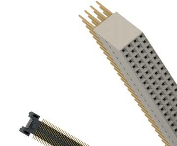
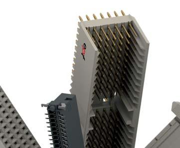
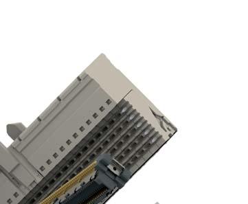
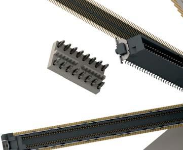
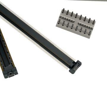
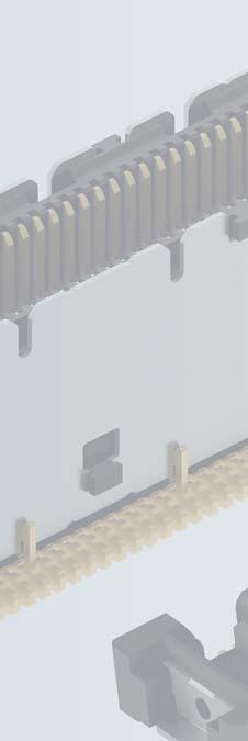
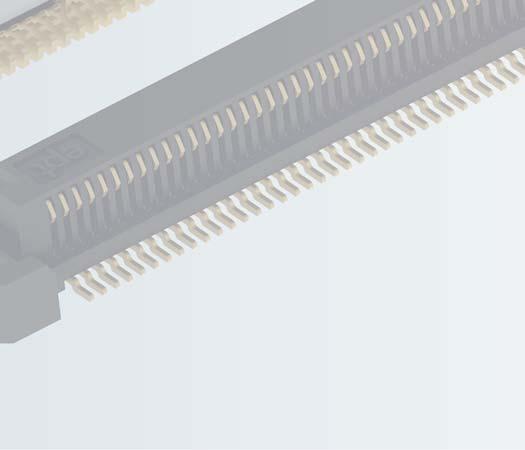
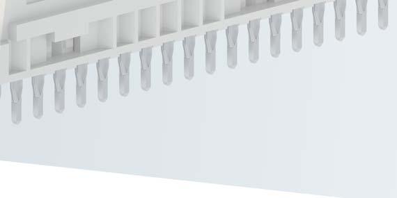
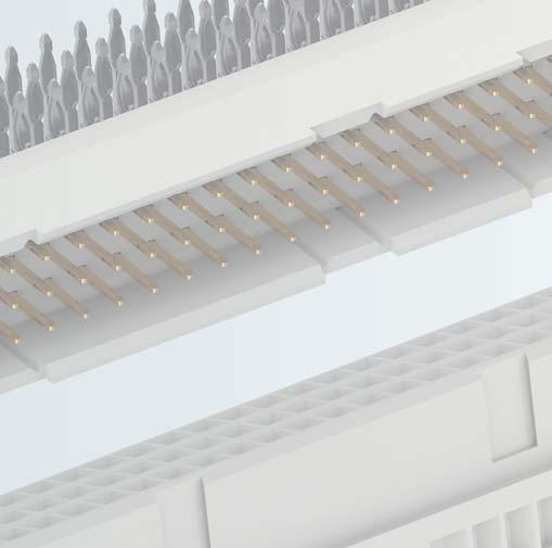
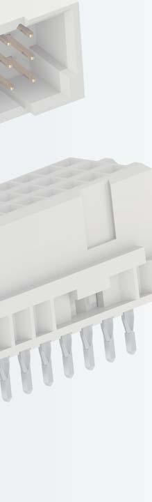
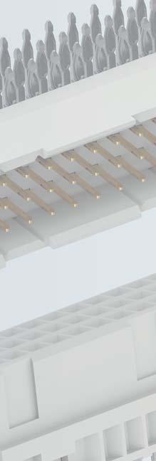
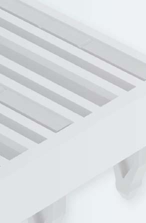
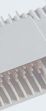
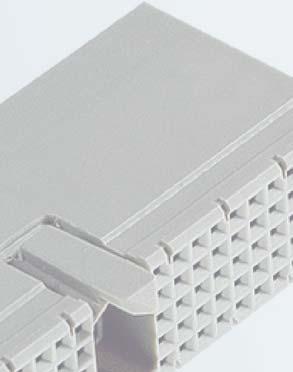
19 Colibri Introduction Colibri 0.5 mm SMT Board-to-Board Connector System Connectors for COM Express Key Features: Termination ept s Colibri connector is a shielded, 2-row, SMT interconnect system in 0.5 mm pitch. It is designed to meet the requirements PICMG COM Express, but also of SFF-SIG Core Express. Furthermore Colibri products are compatible with all common connectors available on the market and extensively tested. The connector system is available with 8 mm and 5 mm stacking height plus 220 and 440 pins. count as well as multiple stacking heights are available on request. meets the requirements of PICMG COM Express and SFF-SIG CoreExpress intermatability with available connectors in the market tested up to 5 Gbit/s; applications up to 8 Gbit/s possible robust connector design integrated Pick & Place area packed in Tape & Reel Applications: COM Express CoreExpress mezzanin board-to-board VITA59 SMT Parallel 5 or 8 mm Applications GBps High Speed High Density 18 ept GmbH I Tel. +49 (0) / I Fax +49 (0) / I sales@ept.de I
 for COM Module area for pick-and-place optional: pick-and-place cap 0.")
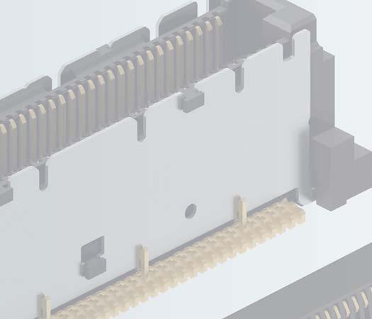
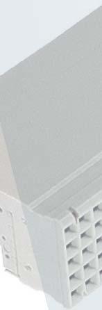
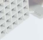
20 Colibri Overview Type Number of contacts Board type Mating connector Page reference Colibri Plug 220 / 440 COM Express Carrier Board Colibri Receptacle p. 22 Colibri Receptacle 220 / 440 COM Express COM Module Colibri Plug p. 24 Receptacle (Female connector) for COM Module area for pick-and-place optional: pick-and-place cap 0.5 mm pitch 196 signal and 24 ground pins guide posts SMT fixing Plug (Male connector) for Carrier Board shield The arrangement of 196 signal and 24 ground contacts in 0.5 mm pitch ensures highest contact density. connectors on PCBs. in Tape and Reel ensures optimized processing during automatic assembly. While the Receptacle is placed on the COM Module, the Plug can be found on the Carrier Board. Receptacle and Plug possess integrated areas for pick-and-place assembly. For the Plug there is also an additional pick-and-place cap available. The packaging ept GmbH I Tel. +49 (0) / I Fax +49 (0) / I sales@ept.de I 19


21 Colibri COM Express COM Express, a computer-on-module (COM) form factor, was developed and is maintained by PICMG (PCI Industrial Computer Manufacturers the physical dimensions and placement of the module on the carrier board, but also the connectors used to plug the COM with the carrier board. COM Express modules integrate the core functionalities of a bootable PC, such as CPU, RAM and standard interfaces on a module that is plugged by either one or two connectors on an individually designed carrier board. ept s Colibri release of the PICMG Design Guide for COM Express. The ability to plug a COM Express module onto a carrier board reduces time and cost to develop a product, as the user does not need to understand the often complex details associated with high speed signaling or the latest chip sets. Furthermore, product lifetime can be increased, as newer COM Express modules can simply be plugged onto the carrier board to improve performance. COM Express module sizes: Typical applications: 20 ept GmbH I Tel. +49 (0) / I Fax +49 (0) / I sales@ept.de I
22 Colibri PICMG COM / 440 SMT LCP, UL 94 V-0 Ω Ω 200 VAC MSL ept GmbH I Tel. +49 (0) / I Fax +49 (0) / I sales@ept.de I 21
 Packaging: Tape & Reel, Tray Standards: PICMG COM.")
 22 ept GmbH I Tel.")
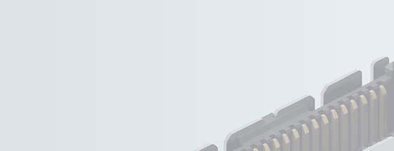
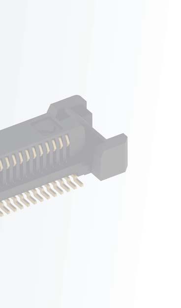
23 Colibri Plug (Male connector / Carrier Board) Type: Plug (Carrier Board) Termination: SMT Number of contacts: 220, 440 Pitch: 0.5 mm Data transfer rate: 5 Gbit/s (8 Gbit/s) Packaging: Tape & Reel, Tray Standards: PICMG COM.0 Technical Specifications on page 21 Dimensions in mm For detailed drawings visit Note Applications up to 8 Gbit/s possible! Mating connector / Application: Colibri Receptacle (p. 24) 22 ept GmbH I Tel. +49 (0) / I Fax +49 (0) / I sales@ept.de I
24 Colibri Plug (Male connector / Carrier Board) 8 mm board-to-board distance 7,45 Tape & Reel cap 440 cap On request 5 mm board-to-board distance 4,45 Tape & Reel cap 440 cap On request ept GmbH I Tel. +49 (0) / I Fax +49 (0) / I sales@ept.de I 23


25 Colibri Receptacle (Female connector / COM Modul) Type: Receptacle (COM Modul) Termination: SMT Number of contacts: 220, 440 Pitch: 0.5 mm Data transfer rate: 5 Gbit/s (8 Gbit/s) Packaging: Tape & Reel, Tray Standards: PICMG COM.0 Technical Specifications on page 21 Dimensions in mm For detailed drawings visit Note Applications up to 8 Gbit/s possible! Mating connector / Application: Colibri Plug 5 mm & 8 mm (p. 22) 24 ept GmbH I Tel. +49 (0) / I Fax +49 (0) / I sales@ept.de I
26 Colibri Receptacle (Female connector / COM Modul) 3,25 Tape & Reel On request ept GmbH I Tel. +49 (0) / I Fax +49 (0) / I sales@ept.de I 25


27 Connectors according to DIN 41612/IEC ept GmbH I Tel. +49 (0) 88 61/ I Fax +49 (0) 88 61/55 07 I sales@ept.de I
28 DIN Contents Introduction 28 Overview 30 The Standard 32 Derating Diagrams 33 THTR Signal Connectors up to 1.5 A Power Connectors up to 5.6 A Power Connectors up to 15 A Special Types and Accessories Shroud 123 Switching Connector Additional Information 131 Coding 132 Pre-mating / late-mating Contacts 133 ept GmbH I Tel. +49 (0) / I Fax +49 (0) / I sales@ept.de I 27
29 DIN Introduction Connectors according to DIN / IEC High Variety and well proven Key Features: The DIN 41612/IEC product 2.54 mm or 5.08 mm pitch. The choices range from signal connectors with a current rating of up to 1.5 A to power connectors that can handle up to 5.6 A or even 15 A. The wealth of variants applications. Standardization ensures that the connectors are compatible with products from different manufacturers. small batches supports pre-mating and late-mating contacts a range of accessories, such as shrouds, Applications: DIN connectors from ept are available in a range of termination technologies. Pre- and late mating and codes provide developers and range of possible applications. high current Terminations Press-fit Through-Hole THTR IDC Application Perpendicular Horizontal Parallel Power 28 ept GmbH I Tel. +49 (0) / I Fax +49 (0) / I sales@ept.de I

30 DIN Introduction Male Connector Type C press-fit zone Tcom press flange for board-lock coding 2.54 mm pitch PBT coding 2.54 mm pitch internal spring contact PBT Female Connector Type C flange for board-lock press-fit zone Tcom press ept GmbH I Tel. +49 (0) / I Fax +49 (0) / I sales@ept.de I 29
31 DIN Overview Type Pitch (mm) max. no. of contacts Signal or power Termination Mating connector Page reference B / 32 / / 32 / 20 Signal 1.5 A Signal 1.5 A solder, THTR solder, THTR start on p Signal 1.0 A IDC start on p. 128 C C, C/2, C/3 C, C/2, C/ / 48 / / 48 / 30 Signal 1.5 A Signal 1.5 A solder, THTR solder, THTR C, C/2, C/3 R, R/2, R/3 C, C/2, C/3 R, R/2, R/3 start on p. 52 C IDC Signal 1.0 A IDC C, R start on p. 128 M / 30 / Signal 1.5 A Signal 1.5 A solder solder start on p. 64 Q / 32 Signal 1.5 A solder start on p. 72 R R, R/2, R/3 R, R/2, R/ / 48 / / 48 / 30 Signal 1.5 A Signal 1.5 A solder, THTR solder, THTR R, R/2, R/3 C, C/2, C/3 R, R/2, R/3 C, C/2, C/3 start on p. 74 D Power 5.6 A Power 5.6 A solder solder start on p ept GmbH I Tel. +49 (0) / I Fax +49 (0) / I sales@ept.de I
32 DIN Overview Type Pitch (mm) max. no. of contacts Signal or Power Termination Mating connector Page reference E Power 5.6 A Power 5.6 A solder solder start on p. 90 F Power 5.6 A Power 5.6 A solder solder start on p. 94 G Power 5.6 A Power 5.6 A solder solder start on p H11, H Power 15 A Power 15 A solder solder H11 start on p. 106 H H15, H Power 15 A Power 15 A solder solder H15 start on p Power 15 A Power 15 A solder solder start on p. 114 VMEx Signal 1.5 A - start on p. 120 Switch Switching connector Signal 1.5 A start on p. 124 ept GmbH I Tel. +49 (0) / I Fax +49 (0) / I sales@ept.de I 31


33 DIN The Standard The Standard / IEC European IEC standard in 1999, DIN 41612/IEC connectors are used to establish a connection between connectors. combined with the high level of connections: boards boards 15 A possible to support the special functions connection, as a soldering connection are also offered with mounting clips connectors on the circuit board in order improve strain relief of the connector during the mating/unmating process. 32 ept GmbH I Tel. +49 (0) / I Fax +49 (0) / I sales@ept.de I
34 DIN Derating Diagram Derating Diagrams Ambient temperature C Ambient temperature C Ambient temperature C Type B, Q, C, R 20 C 1.5 A 70 C 1.1 A 100 C 0.7 A Type D, E, F, G 20 C 5.6 A 70 C 4.0 A 100 C 2.5 A Type H 20 C 15 A 70 C 11 A 100 C 8 A ept GmbH I Tel. +49 (0) / I Fax +49 (0) / I sales@ept.de I 33
35 DIN THTR THTR-Connectors from ept As manufacturers move to one step normal through hole components don t meet the temperature demands ept is pleased to announce the introduction of our high temp DIN connector series, THTR. The connectors temperatures and be soldered in the same production batch as other surface eliminates the need for additional solder before in an additional process step the connector had been pressed into with the other components in the ept connectors in THTR are made from a high temperature resistant plastic, In accordance with RoHS compliance solder process and are rated to a ept also offers additional DIN connectors for electronic applications, 34 ept GmbH I Tel. +49 (0) / I Fax +49 (0) / I sales@ept.de I

36 DIN THTR application of the soldering paste dispenser, or a solder preform. to all solder locations. pin pressed into the solder paste through the hole ept GmbH I Tel. +49 (0) / I Fax +49 (0) / I sales@ept.de I 35
37 DIN B, B/2, B/3 C, C/2, C/3 M, M/2, M/3 VME 64x Q, Q/2 R, R/2, R/3 Standard IEC Number of contacts 64/32/20 96/48/30 78/30/ Contact row designation of male and z a b c d a b a b c female connectors a b c z d Termination Operating temperature range -55 C to +125 C Mechanical Insulator material Engaging and separating force for the 64 pol. < 60 N 32 pol. < 30 N 20 pol. < 18 N 96 pol. < 90 N 48 pol. < 45 N 30 pol. < 28 N 160 N Separating force per contact (test measuring device) > 0.15 N Performance level I Performance level II Performance level III max. operational current C Contact resistance < 20 m < 20 m < 30 m Clearance 1.2 mm Creepage 1.2 mm Insulation resistance > 10 6 M > 10 4 M contact/contact contact/ground Soldering temperature Environment 36 ept GmbH I Tel. +49 (0) / I Fax +49 (0) / I sales@ept.de I
38 DIN D E F G H Standard IEC Number of contacts Contact row designation of male and female connectors a c a c e z b d z b d f b z d Termination Operating temperature range -55 C to+125 C -65 C to +125 C Mechanical Insulator material Engaging and separating force for the Separating force per contact (test measuring device) < 40 N < 60 N < 75 N < 100 N < 80 N < 90 N > 0.15 N > 0.2 N > 0.2 N > 0.2 N > 0.2 N max. operational current C C Contact resistance < 15 m < 8m Clearance 3.0 mm 1.6 mm 4.5 mm 4.5 mm Creepage 3.0 mm 1.6 mm 3.0 mm 8.0 mm 8.0 mm Insulation resistance > 10 6 M contact/contact contact/ground Soldering temperature up to 260 C Environment ept GmbH I Tel. +49 (0) / I Fax +49 (0) / I sales@ept.de I 37
39 DIN Plated through-hole according to IEC new board surfaces. D/E/F/G PCB thickness min. 1.6 mm min. 1.6 mm min. 1.6 mm B Plated hole Ø / mm Ø / mm Ø / mm C Drill hole 1.0 ± mm 1.15 ± mm 1.75 ± mm D Cu plating min. 25 μm min. 25 μm min. 25 μm E imm. Sn plating max. 1.5 μm max. 1.5 μm max. 1.5 μm F Annular ring min. 0.1 mm min. 0.1 mm min. 0.1 mm PCB thickness min. 1.6 mm min. 1.6 mm min. 1.6 mm B Plated hole Ø / mm Ø / mm Ø / mm C Drill hole 1.0 ± mm 1.15 ± mm 1.75 ± mm D Cu plating min. 25 μm min. 25 μm min. 25 μm E μm Au more than μm Ni μm Au more than μm Ni μm Au more than 2.5 5μm Ni F Annular ring min. 0.1 mm min. 0.1 mm min. 0.1 mm PCB thickness min. 1.6 mm min. 1.6 mm min. 1.6 mm B Plated hole Ø / mm Ø / mm Ø / mm C Drill hole 1.0 ± mm 1.15 ± mm 1.75 ± mm D Cu plating min. 25 μm min. 25 μm min. 25 μm E OSP* 0.15 μm 0.15 μm 0.15 μm F Annular ring min. 0.1 mm min. 0.1 mm min. 0.1 mm PCB thickness min. 1.6 mm min. 1.6 mm min. 1.6 mm B Plated hole Ø / mm Ø / mm Ø / mm C Drill hole 1.0 ± mm 1.15 ± mm 1.75 ± mm D Cu plating min. 25 μm min. 25 μm min. 25 μm E 5 15 μm 5 15 μm 5 15 μm F Annular ring min. 0.1 mm min. 0.1 mm min. 0.1 mm * OSP = Organic Solderabiltity Preservatives 38 ept GmbH I Tel. +49 (0) / I Fax +49 (0) / I sales@ept.de I

40 DIN Technical Information PCB thickness offers three Tcom press variants for different printed circuit B, B/2, B/3 C, C/2, C/3 102-xxxxx xxxxx xxxxx xxxxx xxxxx xxxxx-03 Hole diameter 0.85 mm In addition to the 1.0 standard hole, for connectors a Tcom press zone for the 0.85 mm hole is available. This provides more space between two plated-through holes and there can be an additional circuit between the drill holes. for 0.85 mm Tcom press B, B/2, B/3 C, C/2, C/3 102-xxxxx-xx 104-xxxxx-xx Tcom press 1.0 mm/0.85 mm ept GmbH I Tel. +49 (0) / I Fax +49 (0) / I sales@ept.de I 39
41 DIN Type B Type: Termination: Number of contacts: Pitch: Operational current: Packaging: Standard: Press-fit, solder, THTR 2.54 mm Tube Dimensions in mm Hole pattern For detailed drawings visit Accessories Mating connector / Application: Type B Female connector (p. 42) 40 ept GmbH I Tel. +49 (0) / I Fax +49 (0) / I sales@ept.de I
42 DIN Type B Press-fit - Performance level II 3.4 mm 13 mm b a b a On request b a performance level I + III or customized special contact length contact arrangement Solder - Performance level II 3.0 mm angled 3.0 mm straight 13 mm angled b b a a On request performance level I + III or customized special contact length contact arrangement THTR - Performance level II 3.0 mm angled b a 64 b a ept GmbH I Tel. +49 (0) / I Fax +49 (0) / I sales@ept.de I 41
43 DIN Type B Type: Termination: Number of contacts: Pitch: Operational current: Packaging: Standard: Female connector straight Press-fit, solder, THTR 2.54 mm Tube Dimensions in mm Hole pattern For detailed drawings visit Accessories Note / Options Mating connector / Application: Type Q Male connector (p. 72) 42 ept GmbH I Tel. +49 (0) / I Fax +49 (0) / I sales@ept.de I

44 DIN Type B Press-fit - Performance level II 3.2 mm 4.6 mm 13 mm 17 mm 32 b > 1.5 mm a a b mm mm > 2.8 mm > 1.5 mm On request performance level I + III or customized special contact length alternative contact surface Sn e. g. for WireWrap contact arrangement Solder - Performance level II 2.5 mm 3.4 mm 4.6 mm 13 mm 5.5 mm manual soldering with solder lug 32 a b On request THTR - Performance level II performance level I + III or customized special contact length contact arrangement 2.5 mm 3.4 mm 4.6 mm a 32 b ept GmbH I Tel. +49 (0) / I Fax +49 (0) / I sales@ept.de I 43
45 DIN Type B/2 Type: Termination: Number of contacts: Pitch: Operational current: Packaging: Standard: Press-fit, solder, THTR 2.54 mm Tray Dimensions in mm Hole pattern For detailed drawings visit Accessories Mating connector / Application: 44 ept GmbH I Tel. +49 (0) / I Fax +49 (0) / I sales@ept.de I
46 DIN Type B/2 Press-fit - Performance level II 3.4 mm 13 mm b a On request b a performance level I + III or customized special contact length contact arrangement Solder - Performance level II 3.0 mm angled 3.0 mm straight 13 mm b b a a On request performance level I + III or customized special contact length contact arrangement THTR - Performance level II 3.0 mm angled b a 32 b a ept GmbH I Tel. +49 (0) / I Fax +49 (0) / I sales@ept.de I 45
47 DIN Type B/2 Type: Termination: Number of contacts: Pitch: Operational current: Packaging: Standard: Female connector straight Press-fit, solder, THTR 2.54 mm Tray Dimensions in mm Hole pattern For detailed drawings visit Accessories Mating connector / Application: Type B/2 Male connector (p. 44) 46 ept GmbH I Tel. +49 (0) / I Fax +49 (0) / I sales@ept.de I
48 DIN Type B/2 Press-fit - Performance level II a b mm 4.6 mm 13 mm 17 mm mm mm > 2.8 mm mm mm > 2.8 mm On request performance level I + III or customized special contact length alternative contact surface Sn e. g. for WireWrap contact arrangement Solder - Performance level II 2.5 mm 4 mm 13 mm 5.5 mm Manual soldering with solder lug a b On request performance level I + III or customized contact arrangement THTR - Performance level II 2.5 mm 4 mm 16 a b ept GmbH I Tel. +49 (0) / I Fax +49 (0) / I sales@ept.de I 47
49 DIN Type B/3 Type: Termination: Number of contacts: Pitch: Operational current: Packaging: Standard: Press-fit, solder 2.54 mm Tray Dimensions in mm Hole pattern For detailed drawings visit Accessories Mating connector / Application: 48 ept GmbH I Tel. +49 (0) / I Fax +49 (0) / I sales@ept.de I
50 DIN Type B/3 Press-fit - Performance level II 3.4 mm 13 mm b a On request performance level I + III or customized special contact length contact arrangement Solder - Performance level II 3.0 mm angled 3.0 mm straight 13 mm angled b b a a On request performance level I + III or customized special contact length contact arrangement ept GmbH I Tel. +49 (0) / I Fax +49 (0) / I sales@ept.de I 49
51 DIN Type B/3 Type: Termination: Number of contacts: Pitch: Operational current: Packaging: Standard: Female connector straight Press-fit, solder 2.54 mm Tray Dimensions in mm Hole pattern For detailed drawings visit Accessories Mating connector / Application: 50 ept GmbH I Tel. +49 (0) / I Fax +49 (0) / I sales@ept.de I
52 DIN Type B/3 Press-fit - Performance level II mm 4.6 mm 13 mm 17 mm mm mm > 2.8 mm On request performance level I + III or customized special contact length alternative contact surface Sn e. g. for WireWrap contact arrangement Solder - Perfomance level II 2.5 mm 4 mm 13 mm 5.5 mm Manual soldering with solder lug a b On request performance level I + III or customized special contact length contact arrangement ept GmbH I Tel. +49 (0) / I Fax +49 (0) / I sales@ept.de I 51
53 DIN Type C Type: Termination: Number of contacts: Pitch: Operational current: Packaging: Standard: Press-fit, solder, THTR 2.54 mm Tube Dimensions in mm Hole pattern For detailed drawings visit Accessories Mating connector / Application: 52 ept GmbH I Tel. +49 (0) / I Fax +49 (0) / I sales@ept.de I
54 DIN Type C Press-fit - Performance level II 3.4 mm 13 mm c a b c b a c b a c b a On request performance level I + III or customized special contact length contact arrangement Solder - Performance level II THTR - Performance level II 3.0 mm angled 3.0 mm straight 13 mm angled 3.0 mm angled c b a b c a c b a c b a c b a b c a c b a b c a On request performance level I + III or customized special contact length contact arrangement ept GmbH I Tel. +49 (0) / I Fax +49 (0) / I sales@ept.de I 53
55 DIN Type C Type: Termination: Number of contacts: Pitch: Operational current: Packaging: Standard: Female connector straight Press-fit, solder, THTR 2.54 mm Tube L Hole pattern Dimensions in mm For detailed drawings visit Accessories Similar products Mating connector / Application: Type R Male connector (p. 74) 54 ept GmbH I Tel. +49 (0) / I Fax +49 (0) / I sales@ept.de I
56 DIN Type C Press-fit - Performance level II 32 a b c a b c a 3.2 mm 4.6 mm 13 mm 17 mm mm mm > 2.8 mm mm mm > 2.8 mm b > 1.5 mm c a b c 96 > 1.5 mm On request contact arrangement performance level I + III or customized special contact length alternative contact surface Sn e. g. for WireWrap Solder - Performance level II 2.5 mm 3.4 mm 4.6 mm 13 mm Solder lug a 32 b c a b c a 64 b c a b c On request contact arrangement performance level I + III or customized special contact length THTR - Performance level II 2.5 mm 3.4 mm 4.6 mm a 64 b c a b c 96 ept GmbH I Tel. +49 (0) / I Fax +49 (0) / I sales@ept.de I 55
57 DIN Type C/2 Type: Termination: Number of contacts: Pitch: Operational current: Packaging: Standard: Press-fit, solder, THTR 2.54 mm Tray Dimensions in mm Hole pattern For detailed drawings visit Accessories Mating connector / Application: 56 ept GmbH I Tel. +49 (0) / I Fax +49 (0) / I sales@ept.de I
58 DIN Type C/2 Press-fit - Performance level II 3.4 mm 13 mm b c a c a b c b a On request performance level I + III or customized special contact length contact arrangement Solder - Performance level II 3.0 mm angled 3.0 mm straight 13 mm angled c b a c b a c b a On request performance level I + III or customized special contact length contact arrangement THTR - Performance level II 3.0 mm angled b c a c a b c b a ept GmbH I Tel. +49 (0) / I Fax +49 (0) / I sales@ept.de I 57
59 DIN Type C/2 Type: Termination: Number of contacts: Pitch: Operational current: Packaging: Standard: Female connector straight Press-fit, solder, THTR 2.54 mm Tray Dimensions in mm Hole pattern For detailed drawings visit Accessories Mating connector / Application: 58 ept GmbH I Tel. +49 (0) / I Fax +49 (0) / I sales@ept.de I
60 DIN Type C/2 Press-fit - Performance level II 16 a b c a mm 4.6 mm 13 mm 17 mm mm mm > 2.8 mm b 32 > 1.5 mm c a b > 1.5 mm c On request performance level I + III or customized special contact length alternative contact surface Sn e. g. for WireWrap contact arrangement Solder - Performance level II 2.5 mm 3.4 mm 4.6 mm 13 mm 5.5 mm Manual soldering with solder lug a b c a b c a b c On request THTR - Performance level II performance level I + III or customized special contact length contact arrangement 2.5 mm 3.4 mm 4.6 mm a b 32 c a b c ept GmbH I Tel. +49 (0) / I Fax +49 (0) / I sales@ept.de I 59
61 DIN Type C/3 Type: Termination: Number of contacts: Pitch: Operational current: Packaging: Standard: Press-fit, solder 2.54 mm Tray Dimensions in mm Hole pattern For detailed drawings visit Accessories Mating connector / Application: 60 ept GmbH I Tel. +49 (0) / I Fax +49 (0) / I sales@ept.de I
62 DIN Type C/3 Press-fit - Performance level II 3.4 mm 13 mm b 20 a b 30 a c c On request performance level I + III or customized special contact length contact arrangement Solder - Performance level II 3.0 mm angled 3.0 mm straight 13 mm angled b 20 a b 30 a c c On request performance level I + III or customized special contact length contact arrangement ept GmbH I Tel. +49 (0) / I Fax +49 (0) / I sales@ept.de I 61
63 DIN Type C/3 Type: Termination: Number of contacts: Pitch: Operational current: Packaging: Standard: Female connector straight Press-fit, solder 2.54 mm Tray Dimensions in mm Hole pattern For detailed drawings visit Accessories Mating connector / Application: 62 ept GmbH I Tel. +49 (0) / I Fax +49 (0) / I sales@ept.de I
64 DIN Type C/3 Press-fit - Performance level II 4.6 mm 13 mm 17 mm a b c a b c On request performance level I + III or customized special contact length alternative contact surface Sn e. g. for WireWrap contact arrangement Solder - Performance level II 2.5 mm 3.4 mm 4.6 mm 13 mm 5.5 mm Manual soldering with solder lug 20 a b c a b c On request performance level I + III or customized special contact length contact arrangement ept GmbH I Tel. +49 (0) / I Fax +49 (0) / I sales@ept.de I 63

65 DIN Type M Type: Termination: Number of contacts: Pitch: Operational current: Packaging: Standard: Solder 2.54 mm Dimensions in mm Hole pattern For detailed drawings visit Mating connector / Application: 64 ept GmbH I Tel. +49 (0) / I Fax +49 (0) / I sales@ept.de I
66 DIN Type M Hole pattern Solder - Performance level II 3.0 mm / / On request performance level I + III or customized ept GmbH I Tel. +49 (0) / I Fax +49 (0) / I sales@ept.de I 65
67 DIN Type M Type: Termination: Number of contacts: Pitch: Operational current: Packaging: Standard: Female connector straight Press-fit, solder 2.54 mm Tube Dimensions in mm drawing similar For detailed drawings visit Note at the flange. Mating connector / Application: 66 ept GmbH I Tel. +49 (0) / I Fax +49 (0) / I sales@ept.de I
68 DIN Type M Hole pattern Press-fit - Performance level II Solder - Performance level II 4.6 mm 4.6 mm 6/ / / / / / On request performance level I + III or customized special contact length processing tools ept GmbH I Tel. +49 (0) / I Fax +49 (0) / I sales@ept.de I 67
69 DIN Type M Type: Terminaton: Number of contacts: Pitch: Operational current: Packaging: Standard: Female connector straight Press-fit 2.54 mm Tube Dimensions in mm drawing similar For detailed drawings visit Accessories Note Female connectors must be printed circuit at the flange. Mating connector / Application: 68 ept GmbH I Tel. +49 (0) / I Fax +49 (0) / I sales@ept.de I
70 DIN Type M Hole pattern Press-fit - Performance level II Special contact is not pre-loaded 4.6 mm Special contact is pre-loaded 4.6 mm 6/ / / On request performance level I + III or customized special contact length processing tools contact arrangement ept GmbH I Tel. +49 (0) / I Fax +49 (0) / I sales@ept.de I 69

71 DIN Type M/2, M/3 Type: Termination: Number of contacts: Pitch: Operational current: Packaging: Standard: Female connector straight Press-fit, solder 2.54 mm Tray Dimensions in mm M/2 M/3 For detailed drawings visit Note at the flange. Mating connector / Application: 70 ept GmbH I Tel. +49 (0) / I Fax +49 (0) / I sales@ept.de I
72 DIN Type M/2, M/3 Press-fit - Performance level II 4.6 mm M/2 30/2 M/3 12/ On request performance level I + III or customized special contact length processing tools Solder - Performance level II 4.6 mm M/2 30/2 M/3 12/ On request performance level I + III or customized special contact length processing tools Press-fit with special contact - Performance level II 4.6 mm 4.6 mm Special contact is not pre-loaded Special contact is pre-loaded M/2 30/2 M/3 12/ On request performance level I + III or customized special contact length processing tools contact arrangement ept GmbH I Tel. +49 (0) / I Fax +49 (0) / I sales@ept.de I 71

73 DIN Type Q Type: Termination: Number of contacts: Pitch: Operational current: Packaging: Standard: Male connector straight Solder 2.54 mm Dimensions in mm Hole pattern For detailed drawings visit Solder - Performance level II 2.5 mm 4.0 mm b a On request performance level I + III or customized Mating connector / Application: Type B Female connector (p. 42) 72 ept GmbH I Tel. +49 (0) / I Fax +49 (0) / I sales@ept.de I

74 DIN Type Q/2 Type: Termination: Number of contacts: Pitch: Operational current: Packaging: Standard: Male connector straight Solder 2.54 mm Hole pattern Dimensions in mm For detailed drawings visit Solder - Performance level II 2.5 mm 4.0 mm b a On request performance level I + III or customized Mating connector / Application: ept GmbH I Tel. +49 (0) / I Fax +49 (0) / I sales@ept.de I 73
75 DIN Type R Type: Termination: Number of contacts: Pitch: Operational current: Packaging: Standard: Male connector straight Press-fit, solder, THTR 2.54 mm Tube Dimensions in mm For detailed drawings visit Accessories Mating connector / Application: 74 ept GmbH I Tel. +49 (0) / I Fax +49 (0) / I sales@ept.de I
76 DIN Type R Press-fit - Performance level II 4.6 mm 13 mm 17 mm a b c a b c a b c a b c On request performance level I + III or customized special contact length alternative contact surface Sn e. g. for WireWrap contact arrangement Solder - Performance level II THTR - Performance level II 2.5 mm 4 mm 5.5 mm Manual soldering with solder lug 2.5 mm 4 mm a b c a b 32 c a b c a b c a b c a b 64 c a b c a b 96 c On request performance level I + III or customized special contact length contact arrangement ept GmbH I Tel. +49 (0) / I Fax +49 (0) / I sales@ept.de I 75
77 DIN Type R Type: Termination: Number of contacts: Pitch: Operational current: Packaging: Standard: Press-fit, solder, THTR 2.54 mm Tube Dimensions in mm For detailed drawings visit Mating connector / Application: Accessories Type R Male connector (p. 74) 76 ept GmbH I Tel. +49 (0) / I Fax +49 (0) / I sales@ept.de I
78 DIN Type R Press-fit - Performance level II 3 mm 64 c b a On request 96 c b a performance level I + III or customized special contact length contact arrangement Solder - Performance level II 3.0 mm c b 32 a c b a c b a c b a On request performance level I + III or customized special contact length contact arrangement THTR - Performance level II 3.0 mm c b 32 a c b a c b 64 a c b 96 a ept GmbH I Tel. +49 (0) / I Fax +49 (0) / I sales@ept.de I 77
79 DIN Type R/2 Type: Termination: Number of contacts: Pitch: Operational current: Packaging: Standard: Male connector straight Press-fit, solder 2.54 mm Dimensions in mm For detailed drawings visit Mating connector / Application: Accessories 78 ept GmbH I Tel. +49 (0) / I Fax +49 (0) / I sales@ept.de I
80 DIN Type R/2 Press-fit - Performance level II 4.6 mm 13 mm 17 mm b 32 c a a b c On request performance level I + III or customized special contact length alternative contact surface Sn e. g. for WireWrap contact arrangement Solder - Performance level II 2.5 mm 4 mm b 32 c a a b c On request performance level I + III or customized special contact length contact arrangement ept GmbH I Tel. +49 (0) / I Fax +49 (0) / I sales@ept.de I 79
81 DIN Type R/2 Type: Termination: Number of contacts: Pitch: Operational current: Packaging: Standard: Press-fit, solder 2.54 mm Tray Dimensions in mm For detailed drawings visit Mating connector / Application: Accessories 80 ept GmbH I Tel. +49 (0) / I Fax +49 (0) / I sales@ept.de I
82 DIN Type R/2 Press-fit - Performance level II 3.0 mm 32 c b a On request c b a performance level I + III or customized special contact length contact arrangement Solder - Performance level II 3.0 mm 32 c b a On request c b a performance level I + III or customized special contact length contact arrangement ept GmbH I Tel. +49 (0) / I Fax +49 (0) / I sales@ept.de I 81
83 DIN Type R/3 Type: Termination: Number of contacts: Pitch: Operational current: Packaging: Standard: Male connector straight Press-fit, solder 2.54 mm Dimensions in mm For detailed drawings visit Mating connector / Application: Accessories 82 ept GmbH I Tel. +49 (0) / I Fax +49 (0) / I sales@ept.de I
84 DIN Type R/3 Press-fit - Performance level II 30 a b c mm 13 mm 17 mm On request performance level I + III or customized special contact length alternative contact surface Sn e. g. for WireWrap contact arrangement Solder - Performance level II 30 a b c mm 4.0 mm On request performance level I + III or customized special contact length contact arrangement ept GmbH I Tel. +49 (0) / I Fax +49 (0) / I sales@ept.de I 83
85 DIN Type R/3 Type: Termination: Number of contacts: Pitch: Operational current: Packaging: Standard: Press-fit, solder 2.54 mm Tray Dimensions in mm For detailed drawings visit Mating connector / Application: Accessories 84 ept GmbH I Tel. +49 (0) / I Fax +49 (0) / I sales@ept.de I
86 DIN Type R/3 Press-fit - Performance level II 3.0 mm On request 30 c b a performance level I + III or customized special contact length contact arrangement Solder - Performance level II 30 c b a 3.0 mm On request performance level I + III or customized special contact length contact arrangement ept GmbH I Tel. +49 (0) / I Fax +49 (0) / I sales@ept.de I 85
87 DIN Type D Type: Termination: Number of contacts: Pitch: Operational current: Packaging: Standard: Solder Tube Dimensions in mm For detailed drawings visit Accessories Mating connector / Application: 86 ept GmbH I Tel. +49 (0) / I Fax +49 (0) / I sales@ept.de I
88 DIN Type D Solder - Performance level II 3.0 mm angled 3.7 mm straight 16 c a On request c a performance level I + III or customized special contact length contact arrangement ept GmbH I Tel. +49 (0) / I Fax +49 (0) / I sales@ept.de I 87
89 DIN Type D Type: Termination: Number of contacts: Pitch: Operational current: Packaging: Standard: Female connector straight Press-fit, solder Tube Dimensions in mm For detailed drawings visit Accessories Mating connector / Application: 88 ept GmbH I Tel. +49 (0) / I Fax +49 (0) / I sales@ept.de I
90 DIN Type D Press-fit - Performance level II 4.6 mm 6.0 mm 20 mm On request 32 c a hole diameter 1.0 mm hole diameter 1.6 mm hole diameter 1.6 mm performance level I + III or customized special contact length contact arrangement Solder - Performance level II 4.0 mm 20 mm 2.5 mm 4.6 mm 5.5 mm Manual soldering with solder lug 32 a c On request performance level I + III or customized special contact length contact arrangement ept GmbH I Tel. +49 (0) / I Fax +49 (0) / I sales@ept.de I 89
91 DIN Type E Type: Termination: Number of contacts: Pitch: Operational current: Packaging: Standard: Solder Tube Dimensions in mm For detailed drawings visit Accessories Mating connector / Application: 90 ept GmbH I Tel. +49 (0) / I Fax +49 (0) / I sales@ept.de I
92 DIN Type E Solder - Performance level II 2.9 mm Pitch 5.08 mm 2.9 mm Pitch 2.54 mm 3.7 mm e 32 c a e 32 c a On request e c a performance level I + III or customized special contact length contact arrangement ept GmbH I Tel. +49 (0) / I Fax +49 (0) / I sales@ept.de I 91
93 DIN Type E Type: Termination: Number of contacts: Pitch: Operational current: Packaging: Standard: Female connector straight Press-fit, solder Tube Dimensions in mm For detailed drawings visit Accessories Mating connector / Application: 92 ept GmbH I Tel. +49 (0) / I Fax +49 (0) / I sales@ept.de I
94 DIN Type E Press-fit - Performance level II 4.6 mm 20 mm 32 a c e a 32 c e On request a c e performance level I + III or customized special contact length contact arrangement Solder - Performance level II 4.0 mm 20 mm 2.5 mm 4.6 mm 5.5 mm Manual soldering with solder lug a 32 c e a c e a c e On request performance level I + III or customized special contact length contact arrangement ept GmbH I Tel. +49 (0) / I Fax +49 (0) / I sales@ept.de I 93
95 DIN Type F Type: Termination: Number of contacts: Pitch: Operational current: Packaging: Standard: Solder Bohrungen für Codierstifte hole center for polarization pin Dimensions in mm For detailed drawings visit Mating connector / Application: Accessories 94 ept GmbH I Tel. +49 (0) / I Fax +49 (0) / I sales@ept.de I

96 DIN Type F Male Connector Solder - Performance level II Termination length L L L No. of contacts Contact arrangement 3 mm 3 rows below 3 mm 3 rows sideways Artikelnummer 3 mm 2 rows below 32 d b z d b z d b z On request performance level I + III or customized special contact length also in THTR Board-Lock p. 131 contact arrangement ept GmbH I Tel. +49 (0) / I Fax +49 (0) / I sales@ept.de I 95
97 DIN Type F Type: Termination: Number of contacts: Pitch: Operational current: Packaging: Standard: Female connector straight Press-fit, solder Dimensions in mm For detailed drawings visit Accessories Mating connector / Application: 96 ept GmbH I Tel. +49 (0) / I Fax +49 (0) / I sales@ept.de I
98 DIN Type F Press-fit - Performance level II b 32 d z 6.0 mm 22 mm z 32 b d z On request b d performance level I + III or customized special contact length contact arrangement Solder - Performance level II 4.5 mm Ø 1 mm 22 mm 4.5 mm Ø 0.7 mm 5.5 / 10.9 mm Manual soldering with solder lug b 32 d z z b d On request z b d performance level I + III or customized special contact length contact arrangement ept GmbH I Tel. +49 (0) / I Fax +49 (0) / I sales@ept.de I 97
99 DIN Type: Termination: Number of contacts: Pitch: Operational current: Packaging: Standard: Female connector straight Press-fit, solder Dimensions in mm For detailed drawings visit Accessories Mating connector / Application: 98 ept GmbH I Tel. +49 (0) / I Fax +49 (0) / I sales@ept.de I
100 DIN Press-fit - Performance level II b 32 d z 4.6 mm 12.2 mm z b d On request z b d performance level I + III or customized special contact length contact arrangement Solder - Performance level II b 32 d z 4.6 mm z 32 b d z b d On request performance level I + III or customized special contact length contact arrangement ept GmbH I Tel. +49 (0) / I Fax +49 (0) / I sales@ept.de I 99
101 DIN Type G Type: Termination: Number of contacts: Pitch: Operational current: Packaging: Standard: Solder Dimensions in mm For detailed drawings visit Mating connector / Application: Accessories 100 ept GmbH I Tel. +49 (0) / I Fax +49 (0) / I sales@ept.de I
102 DIN Type G Solder - Performance level II 3.0 mm f z d 64 Z b On request performance level I + III or customized contact arrangement ept GmbH I Tel. +49 (0) / I Fax +49 (0) / I sales@ept.de I 101
103 DIN Type G Type: Termination: Number of contacts: Pitch: Operational current: Packaging: Standard: Female connector straight Press-fit, solder Dimensions in mm For detailed drawings visit Accessories Mating connector / Application: 102 ept GmbH I Tel. +49 (0) / I Fax +49 (0) / I sales@ept.de I
104 DIN Type G Press-fit - Performance level II 6.0 mm 22 mm z 64 b d On request f 2 performance level I + III or customized special contact length contact arrangement Solder - Performance level II 4.5 mm Ø 1 mm 22 mm 4.5 mm Ø 0.7 mm 5.5 / 10.9 mm Manual soldering with solder lug z b d f On request performance level I + III or customized special contact length contact arrangement ept GmbH I Tel. +49 (0) / I Fax +49 (0) / I sales@ept.de I 103
105 DIN Type: Termination: Number of contacts: Pitch: Operational current: Packaging: Standard: Female connector straight Press-fit, solder Dimensions in mm For detailed drawings visit Accessories Mating connector / Application: 104 ept GmbH I Tel. +49 (0) / I Fax +49 (0) / I sales@ept.de I
106 DIN Press-fit - Performance level II 4.6 mm 12.2 mm z b d f On request performance level I + III or customized special contact length contact arrangement Solder - Performance level II 4.6 mm z b d f On request performance level I + III or customized special contact length contact arrangement ept GmbH I Tel. +49 (0) / I Fax +49 (0) / I sales@ept.de I 105
107 DIN Type H11 Type: Termination: Number of contacts: Pitch: Operational current: Packaging: Standard: Solder Dimensions in mm For detailed drawings visit Note Mating connector / Application: 106 ept GmbH I Tel. +49 (0) / I Fax +49 (0) / I sales@ept.de I
108 DIN Type H11 Solder - Performance level II 3.5 mm ; ept GmbH I Tel. +49 (0) / I Fax +49 (0) / I sales@ept.de I 107
109 DIN Type H11 Type: Termination: Number of contacts: Pitch: Operational current: Packaging: Standard: Female connector straight Faston Dimensions in mm For detailed drawings visit Faston - Performance level II 5.5 mm Accessories Mating connector / Application: 108 ept GmbH I Tel. +49 (0) / I Fax +49 (0) / I sales@ept.de I
110 DIN Type: Termination: Number of contacts: Pitch: Operational current: Packaging: Standard: Female connector straight Solder Dimensions in mm For detailed drawings visit Solder - Performance level II 5.0 mm Accessories Mating connector / Application: ept GmbH I Tel. +49 (0) / I Fax +49 (0) / I sales@ept.de I 109
111 DIN Type H15 Type: Termination: Number of contacts: Pitch: Operational current: Packaging: Standard: Solder Dimensions in mm For detailed drawings visit Note Mating connector / Application: 110 ept GmbH I Tel. +49 (0) / I Fax +49 (0) / I sales@ept.de I
112 DIN Type H15 Solder - Performance level II 2.8 mm Z On request contact arrangement ept GmbH I Tel. +49 (0) / I Fax +49 (0) / I sales@ept.de I 111
113 DIN Type H15 Type: Termination: Number of contacts: Pitch: Operational current: Packaging: Standard: Female connector straight Faston Dimensions in mm For detailed drawings visit Faston - Performance level II 0.8 mm x 6.3 mm On request Accessories Mating connector / Application: 112 ept GmbH I Tel. +49 (0) / I Fax +49 (0) / I sales@ept.de I
114 DIN Type: Termination: Number of contacts: Pitch: Operational current: Packaging: Standard: Female connector straight Solder Dimensions in mm For detailed drawings visit Solder - Performance level II 4.0 mm 13 mm On request Accessories Mating connector / Application: ept GmbH I Tel. +49 (0) / I Fax +49 (0) / I sales@ept.de I 113
115 DIN Type H7/F24 Type: Termination: Number of contacts: Pitch: Operational current: Packaging: Standard: Solder Dimensions in mm For detailed drawings visit Note Mating connector / Application: 114 ept GmbH I Tel. +49 (0) / I Fax +49 (0) / I sales@ept.de I
116 DIN Type H7/F24 Solder - Performance level II 3.0 mm d 7+24 Z 32 b z On request ept GmbH I Tel. +49 (0) / I Fax +49 (0) / I sales@ept.de I 115
 88 61 / 25 01 0 I Fax +49 (0) 88 61 / 55 07 I E-Mail sales@ept.de I www.")
117 DIN Type H7/F24 Type: Female connector straight Termination: Solder Number of contacts: 24 Pitch: Operational current: Packaging: Standard: Dimensions in mm For detailed drawings visit Mating connector / Application: 116 ept GmbH I Tel. +49 (0) / I Fax +49 (0) / I sales@ept.de I
118 DIN Type H7/F24 Solder - Performance level II 4.5 mm ø 1.0 mm 22 mm 4.5 mm ø 0.7 mm b 16 d z z 16 b d On request 24 z b d performance level I + III or customized special contact length contact arrangement Suitable crimp contacts /SN /SN ept GmbH I Tel. +49 (0) / I Fax +49 (0) / I sales@ept.de I 117
 88 61 / 25 01 0 I Fax +49 (0) 88 61 / 55 07 I E-Mail sales@ept.de I www.")
119 DIN Type: Termination: Number of contacts: Pitch: Operational current: Packaging: Standard: Female connector straight Press-fit, solder Dimensions in mm For detailed drawings visit Mating connector / Application: 118 ept GmbH I Tel. +49 (0) / I Fax +49 (0) / I sales@ept.de I
120 DIN Press-fit - Performance level II 4.6 mm 7+16 z b d z 7+16 b d On request 7+24 z b d performance level I + III or customized special contact length processing tools contact arrangement Solder - Performance level II 4.6 mm 7+16 z b d z 7+16 b d On request 7+24 z b d performance level I + III or customized special contact length contact arrangement Suitable crimp contacts /SN /SN ept GmbH I Tel. +49 (0) / I Fax +49 (0) / I sales@ept.de I 119
121 DIN Type VME 64x Type: Termination: Number of contacts: Pitch: Operational current: Packaging: Standard: Female connector straight Press-fit 2.54 mm Tube... Dimensions in mm..... For detailed drawings visit Accessories Couldn t you find something suitable or having questions? 120 ept GmbH I Tel. +49 (0) / I Fax +49 (0) / I sales@ept.de I
122 DIN Type VME 64x Press fit - Performance level I 4.6 mm 17 mm 160 z a b c d z a b c d z a b c d On request performance level II + III or customized special contact length ept GmbH I Tel. +49 (0) / I Fax +49 (0) / I sales@ept.de I 121
123 DIN Accessories Type: Pitch: Packaging: Standard: 2.54 mm Bulk 95 A-A 15,60 13,85 X 4 x 2,54 = 10,16 9,45 Dimensions in mm 2,54 2,40 0,95 2,54 A A 2,85 0,30 31 x 2,54 = 78,74 85,30 90 For detailed drawings visit X VME mm 6.0 mm 17 mm mm 4.8 mm 17 mm On request different designs and Application: 122 ept GmbH I Tel. +49 (0) / I Fax +49 (0) / I sales@ept.de I
124 DIN Accessories Shroud Type: Pitch: Packaging: Standard: 2.54 mm Bulk Dimensions in mm For detailed drawings visit C/R mm mm mm mm On request different designs and Application: Type R (p. 74) ept GmbH I Tel. +49 (0) / I Fax +49 (0) / I sales@ept.de I 123
125 DIN Additional Information Switching Connector integrated Switches Problem A principle often used for different bus lines via module boards, the so-called however, leads to a new problem, which becomes obvious when one of are located close to each or the whole endeavour of placing the jumper on the correct pins results in and therefore mispositionings can happen. Module plugged-in Module plugged-in Module not plugged-in Daisy-Chain Signal line Jumper plugged-in 124 ept GmbH I Tel. +49 (0) / I Fax +49 (0) / I sales@ept.de I
126 DIN Additional Information Switching Connector integrated Switches A possible solution The integration of switches into a standard connector according to IEC , e. g. into a female connector for the problem described. The contact springs of this C female connector were between the contact springs. In rest position, with the male connector not plugged-in, the adjacent contact springs are short-circuited through placing of the male connector plugged-in, the contact springs are separated from each other through the contact pins of the male connector. The contact tabs of the spring interrupts the connection between the two springs. Due to the switching behavior of the C female connector, the closed when the module board is pulled contact between two contact springs being plugged in when the male connector is pulled out. Application in the VME bus switching function at the positions of the respective signal lines in the connector, the jumpers used so far are no longer Further applications The integrated switching function is not restricted to the positions in the C female connector stated above. A switch in the a, b and c rows of a C female connector IEC and/or between the a and c rows of a C female connector IEC A further application for ept switching connectors are e. is Functional principle of the switching connectors View from the side Switching contacts in rows 2 4 View from the top Switching principle 1 3 Switching contacts across rows ept GmbH I Tel. +49 (0) / I Fax +49 (0) / I sales@ept.de I 125
 126 ept GmbH I Tel.")
127 DIN Switching Connector Type: Termination: Number of contacts: Pitch: Operational current: Packaging: Standard: Female connector straight Press-fit 2.54 mm Tube Dimensions in mm For detailed drawings visit Accessories Mating connector / Application: Type R Male connector (p. 74) 126 ept GmbH I Tel. +49 (0) / I Fax +49 (0) / I sales@ept.de I
128 DIN Switching Connector Press-fit - Performance level II a c 3.2 mm 4.6 mm 13 mm 17 mm mm mm > 2.8 mm mm mm > 2.8 mm On request performance level I + III or customized special contact length contact arrangement bridge positions ept GmbH I Tel. +49 (0) / I Fax +49 (0) / I sales@ept.de I 127

 128 ept GmbH I Tel.")
129 DIN IDC Type B Type: Termination: Number of contacts: Pitch: Operational current: Packaging: Standard: Female connector straight 2.54 mm Dimensions in mm For detailed drawings visit IDC - Performance level II On request strain relief bracket ribbon cable also available in solder/ Mating connector / Application: Note Type Q Male connector (p. 72) 128 ept GmbH I Tel. +49 (0) / I Fax +49 (0) / I sales@ept.de I
130 DIN IDC Type C Type: Termination: Number of contacts: Pitch: Operational current: Packaging: Standard: Female connector straight 2.54 mm Dimensions in mm For detailed drawings visit IDC - Performance level II 64 a b c On request 96 a b c strain relief bracket ribbon cable also available in solder/ Mating connector / Application: Note Type R Male connector (p. 74) ept GmbH I Tel. +49 (0) / I Fax +49 (0) / I sales@ept.de I 129
131 DIN Additional Information IDC IDC Insulation displacement connection circuit boards. In this connection insulation displacement contacts with their insulation intact and then pressed into the contacts. The insulation is displacement contacts and the wire is connected to the contacts. reliable contact closure. Connections IDC Insulator material Temperature range 55 C to C approx pf Operational current 1 A at 20 C Operational voltage Test voltage Contact resistance Insulation resistance Environment 30 mω 10 6 MΩ 130 ept GmbH I Tel. +49 (0) / I Fax +49 (0) / I sales@ept.de I

132 DIN Additional Information As an alternative to the rivet and/ or screw fastening of the male and/ connectors can also be mounted and tension. The connections are strong enough to hold the connector onto the plated mounting holes, soldering the the strain relief of the connector during insertion and/or withdrawal. Ø F h h < 20 N > 10 N > 25 N < 20 N > 5 N > 25 N xxx-xxxxxc1 xxx-xxxxxc2 xxx-xxxxxc3 1.6 mm 2.4 mm 3.6 mm F m : max. mounting force per Board-Lock F h : min. retention force per Board-Lock Ordering example: C-FL/LP 1.6 mm, part number C1 Ø F h h < 30 N > 10 N > 20 N < 30 N > 7.5 N > 20 N xxx-xxxxxc1 xxx-xxxxxc2 xxx-xxxxxc3 1.6 mm 2.4 mm 3.6 mm F m : max. mounting force per Board-Lock F h : min. retention force per Board-Lock Ordering example: C-ML/LP 1.6 mm, part number C1 ept GmbH I Tel. +49 (0) / I Fax +49 (0) / I sales@ept.de I 131

133 DIN Additional Information Coding Coding without loosing Contacts Type B and C The integrated coding of the connectors coding, coding wedges are inserted into the female connector and matching material of the male connector with coding pliers. 1) Male connector 2) Female connector 1) Break-out coding 2) Insert coding wedge into the female connector Stars Type D, E, F and G holes can be drilled into the male connector and pins can be inserted into the female connector in matching positions. Drill coding hole with gauge. Insert coding pin into the coding hole using the insertion tool. Bore gauge Insertion tool Coding pin items Type H11 and H ept GmbH I Tel. +49 (0) / I Fax +49 (0) / I sales@ept.de I
134 Pre-mating and late-mating Contacts x y x y x y x y x y x y x y DIN Additional Information Pre-mating and late-mating Contacts - For DIN type B, C, R, D, E, F, G The pre-mating contact can - as special contact arrangement - be inserted into B C R D E F G B, B/2, B/3, C, C/2, C/ R, R/2,R/3 Mating side Termination side D E E F, G On request other lengths possible for pre-mating and late-mating ept GmbH I Tel. +49 (0) / I Fax +49 (0) / I sales@ept.de I 133

 88 61")


135 134 ept GmbH I Tel. +49 (0) / I Fax +49 (0) / I sales@ept.de I
136 flexilink jumper Contents ept GmbH I Tel. +49 (0) / I Fax +49 (0) / I sales@ept.de I 135
137 flexilink jumper Press-fit Horizontal Power 136 ept GmbH I Tel. +49 (0) / I Fax +49 (0) / I sales@ept.de I


138 flexilink jumper contact bridge 2 or 4 mm pitch for more flexibility 2 mm 1 mm 5,8 mm ept Tcom press The connector is placed at the desired position. The support tool ensures the correct alignment of the PCBs. By using the lever of the press the connector is pressed-in with little effort. The pressfit zone absorbs the force through deformation. The connection is gas tight and mechanically very strong. There s no need for an additional soldering of the component. ept GmbH I Tel. +49 (0) / I Fax +49 (0) / I sales@ept.de I 137
139 flexilink jumper Number of contact bridges 2-15 Termination Operating temperature range -55 C to +125 C Insulator material Colour insulator material Contact material Copper alloy Contact surface Sn Mechanical Operational current Clearance and creepage Flammability 138 ept GmbH I Tel. +49 (0) / I Fax +49 (0) / I sales@ept.de I
140 flexilink jumper A D min. 25 μm min. 25 μm E max. 1.5 μm imm. Sn F ept GmbH I Tel. +49 (0) / I Fax +49 (0) / I sales@ept.de I 139


141 flexilink jumper Type: non-pluggable bridge connector Number of contact bridges: 2 to 15 Pitch: 2 mm or 4 mm Operational current: 10 A at 30 C Packaging: Bulk goods Standard: Technical Specifications on page 138 8,70 Bestückter jumper / assembled jumper 2,75 1,40 2,2 max. 2 PCB 1 max. 2 0,60 1 max. 0,30 0,90 0,59 Dimensions in mm 5,80 2 Hole pattern 2,30 0,10 1.) 1 Couldn t find something suitable or having questions? We will pleased to help you! Call us: / ept GmbH I Tel. +49 (0) / I Fax +49 (0) / I sales@ept.de I
 88 61 / 25 01 0 I Fax +49 (0) 88 61 / 55 07 I E-Mail")
142 flexilink jumper ept GmbH I Tel. +49 (0) / I Fax +49 (0) / I sales@ept.de I 141


143 VarPol Connectors Pin Headers and Socket Strips 142 ept GmbH I Tel. +49 (0) / I Fax +49 (0) / I sales@ept.de I
144 VarPol Contents Introduction 144 Overview 145 Explanation 146 PCB Distances VarPol Female Connector 150 VarPol Guiding Block 152 VarPol Straight Pin Header 154 VarPol Angled Pin Header 156 Socket Connector 158 ept GmbH I Tel. +49 (0) / I Fax +49 (0) / I sales@ept.de I 143


145 VarPol Introduction High Quality, Adaptable and Robust Key Features: Termination Pin headers and sockets from ept offer a plethora of possibilities for connecting circuit boards. One or two rows, variable pin counts, different termination lengths, straight or angled the choice is yours! The product also allows for seamlessly connecting sockets. In addition, Tcom press, our tried and eliminate the soldering process and greatly increase connection reliability. a large selection of contact lengths and termination lengths a choice of performance levels: 50 and 200 mating cycles sockets can be joined end-to-end simple and inexpensive processing Tcom press Applications: Board-to-Board distance from mm to mm no soldering process thanks to Press-fit Solder Perpendicular Parallel 144 ept GmbH I Tel. +49 (0) / I Fax +49 (0) / I sales@ept.de I

146 VarPol Overview max. Type Pitch (mm) number of contacts Termination Mating connector Page reference VarPol Female connector / 108 solder VarPol Female connector Pin header p. 150 VarPol straight pin header / 108 VarPol Female connector p. 154 VarPol angled pin header / 108 VarPol Female connector p. 156 VarPol socket connector / 64 VarPol socket connector p mm pitch VarPol Female connector VarPol Pin header PBT press-fit zone Tcom press 2.54 mm pitch connection contacts from 5.2 mm to 25 mm PBT press-fit zone Tcom press transfer zone from 3.4 mm to 11 mm ept GmbH I Tel. +49 (0) / I Fax +49 (0) / I sales@ept.de I 145
147 VarPol Explanation Stack it with VarPol VarPol pin headers and sockets based on connect circuit boards with one another in parallel: up to mm using various termination lengths of the multi-pin connector selectable (no upper limit, as the connectors can be arranged next to one another without the loss of a pitch) technology Connecting the connector with the ensures a highly robust and resilient connections, such as with the Tcom press from ept, offer demonstrably better contact reliability than soldering connections. The cold welding between the contact and the circuit board hole resulting from press-in is highly mechanically stable and of a high electrical quality. It is remarkably easy and reliable to process using the associated processing tools offered by ept. It is also possible to vertically stack multiple circuit boards, whereby female used. Board-to-board distances of mm up to can be achieved here. Using a guiding system on the underside of the upper circuit board also supports stable contact management and prevents mismating. Angled pin headers provide the option to implement right-angled connections with the same level of versatility and reliability, in addition to the parallel connection of circuit boards. 146 ept GmbH I Tel. +49 (0) / I Fax +49 (0) / I sales@ept.de I
148 VarPol PCB Distances System: VarPol Female connector / VarPol Pin header System: VarPol Female connector / VarPol Female connector without guiding block ept GmbH I Tel. +49 (0) / I Fax +49 (0) / I sales@ept.de I 147
149 VarPol Number of contacts 2 to to 64 Operating temperature range -55 C to +125 C Insulator material Contact material Copper alloy Contact surface Au over NiP over Ni Sn or Au over Ni Mechanical Pitch 2.54 mm Mating force per pin max. 1.8 N Separating force per pin max. 0.6 N min. 1 N Durability Performance level II = 250 mating cycles Performance level III = 50 mating cycles - Operational current max. 1 A Operating voltage Contact resistance < 20 mω < 10 mω 1.2 mm > 0.6 mm Insulation resistance Flammability > 10 6 MΩ RoHS compliant 148 ept GmbH I Tel. +49 (0) / I Fax +49 (0) / I sales@ept.de I
150 VarPol Plated through-hole according to IEC new board surfaces. Ø 1.0 mm A PCB thickness min. 1.4 mm B Ø 1 Drill hole 1.15 ± mm D Cu plating min. 25 μm E imm. Sn plating max. 1.5 μm F Annular ring min. 0.1 mm A PCB thickness min. 1.4 mm B Ø 1 Drill hole 1.15 ± mm D Cu plating min. 25 μm E μm Au over μm Ni F Annular ring min 0.1 mm A PCB thickness min. 1.4 mm B Ø 1 Drill hole 1.15 ± mm D Cu plating min. 25 μm E OSP* with μm F Annular ring min. 0.1 mm A PCB thickness min. 1.4 mm B Ø 1 Drill hole 1.15 ± mm D Cu plating min. 25 μm E 5 15 μm F Annular ring min. 0.1 mm * OSP = Organic Solderabiltity Preservatives ept GmbH I Tel. +49 (0) / I Fax +49 (0) / I sales@ept.de I 149

151 VarPol VarPol Female Connector Type: Female connector straight Termination: Press-fit, solder Number of contacts: Pitch: 2.54 mm Operational current: Standard: Technical Specifications on page 148 Dimensions in mm For detailed drawings visit Mating connector / Application: Accessories VarPol Female connector (p. 150) VarPol Straight pin header (p. 154) VarPol Angled pin header (p. 156) 150 ept GmbH I Tel. +49 (0) / I Fax +49 (0) / I sales@ept.de I
152 VarPol VarPol Female Connector Press-fit L mm 12.2 mm 17 mm II III II III Ordering note On request contact arrangement other contact surface Solder L 12.2 mm II III II III Ordering note On request contact arrangement other contact surface ept GmbH I Tel. +49 (0) / I Fax +49 (0) / I sales@ept.de I 151

153 VarPol VarPol Guiding Block Guiding block Dimensions in mm For detailed drawings visit Ordering note 100 contacts -> /1 Note Couldn t find something suitable or having questions? 152 ept GmbH I Tel. +49 (0) / I Fax +49 (0) / I sales@ept.de I
154 VarPol Notes ept GmbH I Tel. +49 (0) / I Fax +49 (0) / I sales@ept.de I 153

155 VarPol VarPol Straight Pin Header Type: Male connector straight Termination: Press-fit Number of contacts: Pitch: 2.54 mm Operational current: Standard: Technical Specifications on page 148 Press-in via shoulders Dimensions in mm Hole pattern For detailed drawings visit Accessories Mating connector / Application: VarPol Female connector (p. 150) 154 ept GmbH I Tel. +49 (0) / I Fax +49 (0) / I sales@ept.de I
156 VarPol VarPol Straight Pin Header Press-fit 1-row Termination length No. of contacts max. 36 No. of contacts max. 108 Part number Y Performance level II Performance level III Performance level II Performance level II nn nn nn nn nn nn nn nn nn nn nn nn nn nn nn nn nn nn nn nn nn nn nn nn nn nn nn Press-fit 2-row Termination length Part number Y Performance level II Performance level III Performance level II Performance level II nn nn nn nn nn nn nn nn nn nn nn nn nn nn nn nn nn nn nn nn nn nn nn nn nn nn nn Ordering note nn=no. of contacts/row Example for pin header: 2-row, 100 contacts Performance level II, length of termination side 3.4 mm, length of mating side 5.2 mm -> Note Performance level II = 250 mating cycles Performance level III = 50 mating cycles On request special contact length other contact surface ept GmbH I Tel. +49 (0) / I Fax +49 (0) / I sales@ept.de I 155
157 VarPol VarPol Angled Pin Header Type: Termination: Press-fit Number of contacts: Pitch: 2.54 mm Operational current: Normen: Technical Specifications on page 148 Dimensions in mm Press-in via shoulders Hole pattern For detailed drawings visit Hole pattern Accessories Mating connector / Application: VarPol Female connector (p. 150) 156 ept GmbH I Tel. +49 (0) / I Fax +49 (0) / I sales@ept.de I
158 VarPol VarPol Angled Pin Header Press-fit 1-row Y 2.8 max Press-fit 2-row Ordering note Note Performance level II = 250 mating cycles Performance level III = 50 mating cycles On request Y special contact length other contact surface max ept GmbH I Tel. +49 (0) / I Fax +49 (0) / I sales@ept.de I 157

159 VarPol Socket Connector Type: Termination: Press-fit Number of contacts: 2-64 Pitch: 2.54 mm Operational current: 1 A Standard: Technical Specifications on page 148 Dimensions in mm Hole pattern Hole pattern For detailed drawings visit Mating connector / Application: 158 ept GmbH I Tel. +49 (0) / I Fax +49 (0) / I sales@ept.de I
160 VarPol Socket Connector Press-fit Ordering note 15 mm termination length -> max. 32 max μm Sn 0.25 μm Au 5 μm Sn 0.25 μm Au Note On request processing tools ept GmbH I Tel. +49 (0) / I Fax +49 (0) / I sales@ept.de I 159

")

161 PC/104, PC/104-Plus 160 ept GmbH I Tel. +49 (0) / I Fax +49 (0) / I sales@ept.de I
162 PC/104, PC/104-Plus Contents Introduction 162 Overview 163 The Standard PC/ PC/104-Plus 170 Accessories: PC/104-Plus 173 ept GmbH I Tel. +49 (0) / I Fax +49 (0) / I sales@ept.de I 161
, and comes with a standardized PC/104 Bus (ISA).")
163 PC/104, PC/104-Plus Introduction PC/104, PC/104-Plus Highest Quality for Established Form Factor PC/104 and PC/104-Plus is a standard for PC-compatible modules which are intermateable to set up a complete computing system. The PC/104 and PC/104-Plus ensures complete hardware and software compatibility, is extremely compact (96 mm x 90 mm), and comes with a standardized PC/104 Bus (ISA). Due to this standardization, different PC/104 cards can be combined Based on PC/104, many different boards are offered such as: Ethernet Key Features: Tcom press PC/104-Plus available for 22 mm Board-to-Board distance shrouds as accessory available individual performance level and contact number possible Applications: PC/104 PC/104-Plus Board-to-Board for PCB distance mm and 22 mm Termination Press-fit Solder Parallel 162 ept GmbH I Tel. +49 (0) / I Fax +49 (0) / I sales@ept.de I

164 PC/104, PC/104-Plus Overview Type Pitch (mm) Number of contacts Termination Mating connector Page reference PC/104 PC/104 Female connector / 64 solder PC/104 Female connector p. 168 PC/104-Plus Female connector solder PC/104-Plus Female connector p. 170 PC/104-Plus PC/104-Plus Female connector 22 mm PC/104-Plus Female connector p. 171 PC/104-Plus Pin header 2 60 PC/104-Plus Female connector p mm pitch PC/104 2-row PBT press-fit zone Tcom press guiding plastic 2 mm pitch PC/104-Plus 4-row press-fit zone Tcom press PBT available with or without transfer zone connection contacts 12 mm ept GmbH I Tel. +49 (0) / I Fax +49 (0) / I sales@ept.de I 163
165 PC/104, PC/104-Plus The Standard PC/104 and PC/104-Plus Since more powerful components are available, the PC/104 systems had to be supplemented with a faster bus system. The PC/104 system was supplemented with the PCI bus and thus it was further developed. This supplement is described in the PC/104- Plus the PC/104 consortium are ensured by using spacers and shrouds. The additional use of spacing bolts is therefore not required. PC/104 and PC/104-Plus Connector While the PC/104 bus comprises two connectors with 40 and 64 pins which can be placed side-by-side and a grid size of 2.54 mm, the PC/104-Plus features 120 pins with a distance of 2.00 mm. By using connectors with long pins in be stacked on top of each other (see 164 ept GmbH I Tel. +49 (0) / I Fax +49 (0) / I sales@ept.de I
166 PC/104, PC/104-Plus The Standard PC/104 and PC/104-Plus connectors from ept offer various advantages: The female connectors are pressed in No additional costs due to complex manual soldering No reworking at the rear mating zone (solder bridges, solder splashes) forces; therefore bending of the rear mating zone is prevented When female connectors with rear mating zone are pressed in, a guiding block is pushed up from below. This offers the following advantages: No bending of the rear mating zone Serves as spacer so that the clearance of 0.6 is achieved when the modules are plugged in Serves as support tool when pressing in and prevents that the strip lines between the through connections are damaged. Unplugged PC/104-Plus Printed circuit board 2-pin headers PC/104-Plus Shroud PC/104-Plus Female connector PCB by additional press in of the shroud housing onto the rear mating zone. Printed circuit board Within the scope of PC/104 and PC/104-Plus applications, upon request ept also offers various customer-speci- grid. Shroud PC/104-Plus Female connector Printed circuit board ept GmbH I Tel. +49 (0) / I Fax +49 (0) / I sales@ept.de I 165
167 PC/104, PC/104-Plus PC/104 PC/104 PC/104-Plus Mechanical Ω Ω 166 ept GmbH I Tel. +49 (0) / I Fax +49 (0) / I sales@ept.de I
168 PC/104, PC/104-Plus Plated through-hole according to IEC new board surfaces. PC/104-Plus PC/104 A B C D E F A B C D E F A B C D E OSP* F A B C D E F * OSP = Organic Solderabiltity Preservatives ept GmbH I Tel. +49 (0) / I Fax +49 (0) / I sales@ept.de I 167

169 PC/104, PC/104-Plus PC/104 Female Connector Type: Female connector straight Termination: Press-fit, solder Number of contacts: 40, 64 Pitch: 2.54 mm Operational current: 1.9 A Packaging: Tray Standard: PC/104 Technical Specifications on page 166 Dimensions in mm For detailed drawings visit Accessories Note At a contact length of 12.2 mm a guiding block is scope of delivery. Mating connector / Application: PC/104 Female connector (p. 168) VarPol Straight pin header (p. 154) 168 ept GmbH I Tel. +49 (0) / I Fax +49 (0) / I sales@ept.de I
170 PC/104, PC/104-Plus PC/104 Female Connector Press-fit L 40 II 40 III 64 II 64 III Solder L 40 II 40 III 64 II 64 III ept GmbH I Tel. +49 (0) / I Fax +49 (0) / I sales@ept.de I 169

171 PC/104, PC/104-Plus PC/104-Plus Female Connector Type: Female connector straight Termination: Press-fit, solder Number of contacts: 120 Pitch: 2.0 mm Operational current: 1.7 A Packaging: Tray Standard: PC/104-Plus Technical Specifications on page 166 Dimensions in mm The four drill holes are not required when the PC/104-Plus female connector is used For detailed drawings visit Press-fit - Performance level III Solder - Performance level III L L 120 On request 120 Accessories Mating connector / Application: PC/104-Plus Pin header (p. 172) PC/104-Plus Female connector (p. 170) 170 ept GmbH I Tel. +49 (0) / I Fax +49 (0) / I sales@ept.de I
172 PC/104, PC/104-Plus PC/104-Plus Female Connector 22 mm Type: Female connector straight Termination: Press-fit Number of contacts: 120 Pitch: 2.0 mm Operational current: 1.7 A Packaging: Tray Standard: PC/104-Plus Technical Specifications on page 166 Dimensions in mm pcb hole-tolerance see ept-catalogue For detailed drawings visit Press-fit - Performance level III 120 On request Accessories Mating connector / Application: PC/104-Plus Pin header (p. 172) PC/104-Plus Female connector (p. 170) ept GmbH I Tel. +49 (0) / I Fax +49 (0) / I sales@ept.de I 171
173 PC/104, PC/104-Plus PC/104-Plus Pin Header Type: Male connector straight Termination: Press-fit Number of contacts: 60 Pitch: 2.0 mm Operational current: 1.7 A Packaging: Tray Standard: PC/104-Plus Technical Specifications on page 166 Dimensions in mm For detailed drawings visit Press-fit - Performance level III 60 On request Accessories Mating connector / Application: PC/104-Plus Female connector (p. 170) 172 ept GmbH I Tel. +49 (0) / I Fax +49 (0) / I sales@ept.de I
174 PC/104, PC/104-Plus PC/104-Plus Accessories PC/104-Plus Shroud Dimensions in mm For detailed drawings visit Couldn t find something suitable or having questions? We will be pleased to help you! Call us: / ept GmbH I Tel. +49 (0) / I Fax +49 (0) / I sales@ept.de I 173


")


175 TCA Connectors: AdvancedTCA and MicroTCA 174 ept GmbH I Tel. +49 (0) / I Fax +49 (0) / I sales@ept.de I
176 TCA Connectors Contents AdvancedTCA & MicroTCA - Introduction 176 con:card+ 177 AdvancedTCA Introduction 178 Overview Derating-Diagrams AdvancedTCA Signal AMC B+ 183 AdvancedTCA Power 184 MicroTCA Introduction 186 Overview Derating-Diagrams MicroTCA Signal AMC 191 MicroTCA Power 192 ept GmbH I Tel. +49 (0) / I Fax +49 (0) / I sales@ept.de I 175

 as Mezzanine application.")
177 TCA Connectors AdvancedTCA & MicroTCA Introduction AdvancedTCA & MicroTCA To give consideration to increasing data has developed and adopted (ATCA) and MicroTCA. AdvancedTCA is mainly aimed at the systems requiring maximum availability. With AdvancedTCA it is possible to set than previously possible with proprietary systems. AdvancedTCA can Further advantages are scalable data AdvancedTCA architecture. Another %. AdvancedTCA system even more cost- has developed the AdvancedMC standard (Advanced Mezzanine Card). The AdvancedMC modules are small cards that are plugged in parallel onto a Carrier Board (a carrier board in the TCA subcard) as Mezzanine application. The Carrier Board contains only management the AdvancedMC modules. MicroTCA is based on the approach to plug the AdvancedMC modules direct into systems that do not depend on Carrier Boards and AdvancedTCA. MicroTCA is targeted at applications that do not require a very high computing space requirements and low costs are important. possibilities in the mid and low-end range medical technology or automation technology. R 176 ept GmbH I Tel. +49 (0) / I Fax +49 (0) / I sales@ept.de I


178 TCA Connectors con:card+ con:card+ and AdvancedTCA signal connectors and AdvancedTCA systems can be % modules can hardly con:card+ philosophy. All advantages are described in short below and described in more detail in the con:card+ modules improves the wear resistance by approx. 30 %. Special contact material with contact spring load series processing con:card+ ensures the maximum ept GmbH I Tel. +49 (0) / I Fax +49 (0) / I sales@ept.de I 177
.")
179 TCA Connectors AdvancedTCA Introduction AdvancedTCA For ATCA both signal connectors and power the highest quality standards and help systems much more reliable. connectors contain the stamped and thereby easily processable and highly reliable Tcom press zone. In long-term connection between the complying with the same requirements stability (mating cycles). Key Features: meets requirements Tcom press cost-optimized design Applications: AdvancedTCA High-speed board-to-board R Termination Press-fit Perpendicular Applications GBps High-Speed Power 178 ept GmbH I Tel. +49 (0) / I Fax +49 (0) / I sales@ept.de I

180 TCA Connectors AdvancedTCA Overview AdvancedTCA Type No. of contacts High Speed or Power Mating connector Page reference ATCA Signal AMC B+ 170 High Speed - p. 183 Male connector 16 A ATCA Female connector p. 184 Female connector 16 A ATCA Male connector p. 185 stamped spring contact ATCA Power Female connector guiding hole for Guide Pin PBT press-fit zone Tcom press signal contacts max. 1 A power contacts max. 16 A LCP Signal AMC B+ Guide Spring 0.75 mm pitch press-fit zone needle eye with or without Peg (Pre-centering) ept GmbH I Tel. +49 (0) / I Fax +49 (0) / I sales@ept.de I 179
181 TCA Connectors AdvancedTCA Mechanical Signal AMC B+ AdvancedTCA PICMG AMC.0 PICMG Ω Ω Ω Ω 10 8 Ω 10 Ω 100Ω 180 ept GmbH I Tel. +49 (0) / I Fax +49 (0) / I sales@ept.de I
182 TCA Connectors AdvancedTCA Derating Diagram Derating Diagram ept GmbH I Tel. +49 (0) / I Fax +49 (0) / I sales@ept.de I 181
183 TCA Connectors AdvancedTCA Plated through-hole according to IEC ATCA Signal AMC B+ Ø 0.55 mm Ø 1.0 mm Ø 1.6 mm A B Ø 1 C ± 0.01 mm D E F A B Ø 1 C ± 0.01 mm D E F 182 ept GmbH I Tel. +49 (0) / I Fax +49 (0) / I sales@ept.de I
184 R TCA Connectors AdvancedTCA Signal AMC B+ Type: Termination: Press-fit Number of contacts: 170 Pitch: 0.75 mm Transfer data rate: 12.5 Gbit/s Packaging: Box Standard: PICMG AMC.0 Technical Specifications on page 180 Pos. 170 Pos. 1 Dimensions in mm Hole pattern For detailed drawings visit Peg are two guide pins for the exact positioning of the connector on the PCB. Accessories Note positioning of AMC-Card Application: AMC-Card direct connector ept GmbH I Tel. +49 (0) / I Fax +49 (0) / I sales@ept.de I 183

185 TCA Connectors AdvancedTCA Power Male Connector R Type: Male connector 90 Termination: Press-fit Number of contacts: 22 Signal, 8 Power 26 Signal, 8 Power Operational current: 16 A Packaging: Tray Standard: PICMG Technical Specifications on page 180 Dimensions in mm Hole pattern For detailed drawings visit On request Accessories Mating connector / Application: ATCA Power Female connector (p. 185) 184 ept GmbH I Tel. +49 (0) / I Fax +49 (0) / I sales@ept.de I

186 R TCA Connectors AdvancedTCA Power Female Connector Type: Termination: Number of contacts: Operational current: Packaging: Standard: Female connector straight Press-fit 22 Signal, 8 Power 26 Signal, 8 Power 16 A Tray PICMG Technical Specifications on page ,1 max. 17,25 0,95 17,25 0,95 Dimensions in mm 4,45 Pos. 5-24;27; ,06 Pos. 25, 26, 28-31, 33, 34 22,20 16,15 22,20 16,15 0,95 0,95 Hole pattern 1,50 6,05 ±0,15 6,05 ±0,15 20,9 max. 20,9 max. For detailed drawings visit On request Accessories Mating connector / Application: ATCA Power Male connector (p. 184) ept GmbH I Tel. +49 (0) / I Fax +49 (0) / I sales@ept.de I 185


187 TCA Connectors MicroTCA Introduction MicroTCA For MicroTCA the highest quality standards and help systems much more reliable. Key Features: meets requirements the AMC board Termination Press-fit It is used to clearly position the AMC circuit board in the connector. The deviations on the AMC circuit board by always pushing the module to the opposite wall. As this is moved aligned to the AMC module and mating Applications: MicroTCA High-Speed board-to-board Perpendicular Applications GBps High-Speed Power 186 ept GmbH I Tel. +49 (0) / I Fax +49 (0) / I sales@ept.de I
188 TCA Connectors MicroTCA Overview MicroTCA Type No. of contacts High Speed or Power Mating connector Page reference MTCA Signal AMC 170 High Speed - p. 191 MTCA 12 A MTCA Module Output p. 192 MTCA Module Output 12 A MTCA p. 193 Guide Pin internal spring contacts signal contacts max. 1 A MTCA Power Backplane power contacts max. 12 A lead-in chamfer Guide Spring MTCA Signal AMC press-fit zone Tcom press 0.75 mm pitch ept GmbH I Tel. +49 (0) / I Fax +49 (0) / I sales@ept.de I 187
189 TCA Connectors MicroTCA Mechanical Signal AMC PICMG MTCA.0 PICMG MTCA Ω Ω Ω 10 8 Ω 8 Ω 100Ω 188 ept GmbH I Tel. +49 (0) / I Fax +49 (0) / I sales@ept.de I
190 TCA Connectors MicroTCA Derating Diagram Derating Diagram 15 Current Current x Current [A] Ambient temperature [C ] ept GmbH I Tel. +49 (0) / I Fax +49 (0) / I sales@ept.de I 189
191 TCA Connectors MicroTCA Plated through-hole according to IEC MTCA Signal AMC Ø 0.55 mm Ø 0.6 mm A B C ± 0.01 mm Ø 0.70 D E F A B C ± 0.01 mm Ø 0.70 D E F 190 ept GmbH I Tel. +49 (0) / I Fax +49 (0) / I sales@ept.de I
192 TCA Connectors MicroTCA Signal AMC Type: Signal AMC Termination: Press-fit Number of contacts: 170 Pitch: 0.75 mm Transfer data rate: 12.5 Gbit/s Packaging: Box Standard: PICMG MTCA.0 Technical Specifications on page 188 For detailed drawings visit Peg are two guide pins for the exact positioning of the connector on the PCB. Accessories Note positioning of AMC-Card Application: AMC-Card direct connector ept GmbH I Tel. +49 (0) / I Fax +49 (0) / I sales@ept.de I 191
193 TCA Connectors MicroTCA Power Type: Termination: Number of contacts: Operational current: Packaging: Standard: Power Backplane Press-fit 72 Signal, 24 Power 12 A Tray PICMG MTCA.0 Technical Specifications on page 188 For detailed drawings visit 72 Signal Accessories Mating connector / Application: MicroTCA Power Module Output 192 ept GmbH I Tel. +49 (0) / I Fax +49 (0) / I sales@ept.de I

194 TCA Connectors MicroTCA Power Type: Termination: Number of contacts: Operational current: Packaging: Standard: Power Module Output Press-fit 72 Signal, 24 Power 12 A Tray PICMG MTCA.0 Technical Specifications on page 188 For detailed drawings visit 72 Signal Accessories Mating connector / Application: MicroTCA Backplane Connector ept GmbH I Tel. +49 (0) / I Fax +49 (0) / I sales@ept.de I 193

195 Hardmetric Connectors: hm2.0 for Backplane-Systems 194 ept GmbH I Tel. +49 (0) / I Fax +49 (0) / I sales@ept.de I
196 hm2.0 Contents Introduction 196 Overview 198 The Standard / High-Speed 200 System Modularity 201 Overview: CompactPCI Electrical Characteristics 206 Cross-Talk Pin Lengths 209 hm2.0 Type A 210 hm2.0 Type B hm2.0 Type B hm2.0 Type B hm2.0 Type AB hm2.0 Type AB hm2.0 Type AB hm2.0 Type C 238 hm2.0 Type D 242 hm2.0 Type E 246 hm2.0 Type DE 250 hm2.0 Type F 254 hm2.0 Type L 258 hm2.0 Type M 260 hm2.0 Type N 264 Accessories: Shroud 266 Accessories: Coding Keys 268 Notes 269 ept GmbH I Tel. +49 (0) / I Fax +49 (0) / I sales@ept.de I 195
197 hm2.0 Hardmetric 2 mm for Backplane-Systems Termination The hm2.0 series of hard metric connectors was developed in accordance with the international IEC standard. These shielded connectors have a pitch of 2 mm and are suitable for applications that require high contact density and reliability. Standardization ensures that the connectors are compatible with products from different manufacturers. hm2.0 connectors are used in CompactPCI, a PICMG standard for high-end systems in 19-inch technology with passive backplanes for high requirements as regards of performance, robustness, and reliability. hm2.0 connectors are also increasingly being used for industrial applications that require a robust connection system with high contact density. wide selection of types modular connectors with a pitch of 2 mm 5 or 8 signal rows 12 different pin lengths customized assembly layout as an option available with or without shielding supports a data transfer rate of up to Gbit/s robust design accessories such as shrouds and coding keys telecommunications network systems CompactPCI medical technology industrial PC (IPC) Press-fit Perpendicular 196 ept GmbH I Tel. +49 (0) / I Fax +49 (0) / I sales@ept.de I
 88 61 / 25 01 0 I Fax +49 (0) 88 61 / 55 07 I E-Mail sales@ept.de I www.ept.de 197")
198 hm2.0 press-fit zone Tcom press 2 mm pitch internal spring contact coding with or without shield PBT 2 mm pitch outside contact rows for shielding PBT 5 internal contact rows for signal transmission press-fit zone Tcom press ept GmbH I Tel. +49 (0) / I Fax +49 (0) / I sales@ept.de I 197
199 hm2.0 Overview Type max. no. of Mating Page A A Male connector A Female connector Backplane 5+2-row Daughtercard 5+2-row A Female connector A Male connector start on p. 210 B25 B25 Male connector B25 Female connector Backplane 5+2-row Daughtercard 5+2-row B25 Female connector B25 Male connector start on p. 214 B22 B22 Male connector B22 Female connector Backplane 5+2-row Daughtercard 5+2-row B22 Female connector B22 Male connector start on p. 218 B19 B19 Male connector B19 Female connector Backplane 5+2-row Daughtercard 5+2-row B19 Female connector B19 Male connector start on p. 222 AB25 AB25 Male connector AB25 Female connector Backplane 5+2-row Daughtercard 5+2-row AB25 Female connector AB25 Male connector start on p. 226 AB22 AB22 Male connector AB22 Female connector Backplane 5+2-row Daughtercard 5+2-row AB22 Female connector AB22 Male connector start on p. 230 AB19 AB19 Male connector AB19 Female connector Backplane 5+2-row Daughtercard 5+2-row AB19 Female connector AB19 Male connector start on p. 234 C C Male connector C Female connector Backplane 5+2-row Daughtercard 5+2-row C Female connector C Male connector start on p ept GmbH I Tel. +49 (0) / I Fax +49 (0) / I sales@ept.de I
200 hm2.0 Overview Type max. no. of Mating Page D D Male connector D Female connector Backplane 8+2-row Daughtercard 8+2-row D Female connector D Male connector start on p. 242 E E Male connector E Female connector Backplane 8+2-row Daughtercard 8+2-row E Female connector E Male connector start on p. 246 DE DE Male connector DE Female connector Backplane 8+2-row Daughtercard 8+2-row DE Female connector DE Male connector start on p. 250 F F Male connector F Female connector Backplane 8+2-row Daughtercard 8+2-row F Female connector F Male connector start on p. 254 L L Male connector L Female connector 6 Backplane 6 Daughtercard L Female connector L Male connector start on p. 258 M M Male connector M Female connector Backplane 5+2-row Daughtercard 5+2-row M Female connector M Male connector start on S. 260 N N Male connector N Female connector 3 Backplane 3 Daughtercard N Female connector N Male connector start on p. 264 A, B, B22,B19, C AB25, AB22, AB start on p. 266 Coding Coding keys p. 268 ept GmbH I Tel. +49 (0) / I Fax +49 (0) / I sales@ept.de I 199
201 hm2.0 The Standard / High-Speed The Standard IEC The hardmetric connector system ept hm2.0 was developed and manufactured according to the international standard IEC Thus the user can rely on a worldwide standard for the connection of printed circuit boards using connectors with a large number of contacts. The printed circuit boards can be exchanged between systems without printed circuit boards are compatible regardless of the individual application. ept hm2.0 connectors are designed with a 2 mm metric grid. They can be easily connected in series to form a continuous 2 mm grid. This grid pattern is advantageous when creating a printed circuit board since no space is lost in the individual connector modules. The modules A, D, L and M are equipped with a multi-function block. This in turn can be equipped with the coding keys. The molded guides ensure the correct alignment of the male and female connectors to each other and they offer anti-twist protection before contacting. The coding keys can be inserted or withdrawn using a simple insertion or withdrawal tool. ept offers three different lengths for the front and four different lengths for the rear side. The different contact lengths are necessary because certain signal or ground contacts need to be when adding/removing a module. The mm long contacts are mainly required for the shielding rows z and f. The ends of the insulator material are chamfered to simplify the connection of additional modules and avoid twisting the connectors. The chamfers ensure the exact positioning on the printed circuit boards and stabilize the modules. The connectors must be coded in a modern BUS system to avoid mixing up the printed circuit boards. The possibility of coding has already Coding keys can be manually snapped onto the multi-function block of the connector types A, D, L and M. The different inserts are color-coded and can thus be kept apart. GBps hm2.0 for High-Speed Applications High-speed applications can be realized with hm2.0 connectors from ept. It was possible to attain data transfer rates of up to Gbps under the framework conditions described below. of 1.6 mm and a PCB track length of 115 mm thickness of 4.4 mm and a PCB track length of 400 mm interruptions, the stub effect, the skin effect, and dielectric losses in the application design We would be happy to provide you with more details and the corresponding technical literature on high-speed applications using hm2.0 connectors. Get in touch with us. 200 ept GmbH I Tel. +49 (0) / I Fax +49 (0) / I sales@ept.de I
202 hm2.0 System Modularity ept hm2.0 modules offer a number of possibilities to optimize large contact densities, especially in combination Number Anzahl Kontakte: of contacts: Using module type A, connections with a length of 50 mm can be set up in increments of 25 mm to achieve an overall length as required. The connectors with a multifunction block (types A, M, L) are preferably arranged at the beginning of a connector row. The type B module on the other hand is only arranged between other modules. Due to their inverse-polarity protection the 25 mm type C and N modules are arranged at the end of a connector row. The coding keys in the multifunction block and the modules type C and N ensure that the modules are plugged in correctly. * Total length for Europe cards ** Total length for ETSI boards ept GmbH I Tel. +49 (0) / I Fax +49 (0) / I sales@ept.de I 201
203 hm2.0 Overview CompactPCI Connectors Overview CompactPCI Connectors CompactPCI as the PICMG standard places high requirements on 19-inch high-end systems with passive backplanes as regards robustness, reliability, and performance. CompactPCI platforms are cost optimized, scalable, suitable for harsh environmental conditions, and highly durable. This is why system designers rely on robust, modular, standard-compliant CompactPCI platforms. The PICMG suited for use in CompactPCI applications. Female connectors for daughter card Location Shielding Part number Type A J1/rJ1/J4/rJ4 top Type B22 J2/J5 top Type AB22* rj2/rj5 top Type B19 J3 top Type AB19* rj3 top Type A for telephony J4 divided Type A for telephony (mirrored) rj4 divided * For rear transition card applications the AB connectors are used with AB shroud. All connectors are also available without shield. Male connectors for backplanes Position Contact arrangement * Part number Type A Hot Swap P1 CB***BC Type A Hot Swap for Midplane P1 TP***PT F Type B22 P2 CBBBBBC Type B22 AB compatible P2/P5 *PPPPP* F Type B22 AB compatible P2/P5 *NNNNN* F Type B22 AB compatible P2/P5 *SSSSS* F Type B19 P3 CBBBBBC Type B19 AB compatible P3 *PPPPP* F Type B19 AB compatible P3 *NNNNN* F Type B19 AB compatible P3 *SSSSS* F Type A for telephony P4 ****** Type A for telephony Midplane P4 ****** F Type A P4 TPPPPPT F Type A P4 TNNNNNT F Type A P4 TSSSSST F Type B22 for telephony P5 C*****C Type B22 for telephony, row Z not loaded P5 *****C Type B22 for telephony, row Z not loaded P5 ****** F * Different pin lengths in this row/-not loaded. All connectors are also available with row Z unloaded/for other contact arrangements, please contact ept. 202 ept GmbH I Tel. +49 (0) / I Fax +49 (0) / I sales@ept.de I
204 hm2.0 Overview CompactPCI Connectors Coding keys Color Application Part number Male connector backplane Brilliant blue 5 V P Male connector backplane Cadmium yellow 3.3 V P Male connector backplane Strawberry red Telephony P Female connector daughter card Brilliant blue 5 V J Female connector daughter card Cadmium yellow 3.3 V J Female connector daughter card Strawberry red Telephony J Shroud Position Height Base height PCB thickness Part number Type A P1/P mm 6.3 mm < 2.4 mm /1 Type A P1/P mm 4.9 mm mm /1 Type A P1/P mm 4.5 mm mm /1 Type A P1/P mm 3.7 mm mm /1 Type A P1/P mm 2.9 mm > 4.8 mm /1 Type AB22 P2/P mm 6.3 mm < 2.4 mm /1 Type AB22 P2/P mm 4.9 mm mm /1 Type AB22 P2/P mm 4.5 mm mm /1 Type AB22 P2/P mm 3.7 mm mm /1 Type AB22 P2/P mm 2.9 mm > 4.8 mm /1 Type AB19 P mm 6.3 mm < 2.4 mm /1 Type AB19 P mm 4.9 mm mm /1 Type AB19 P mm 4.5 mm mm /1 Type AB19 P mm 3.7 mm mm /1 Type AB19 P mm 2.9 mm > 4.8 mm /1 The height/bottom thickness of the shroud depends on the thickness of the backplane. ept GmbH I Tel. +49 (0) / I Fax +49 (0) / I sales@ept.de I 203
205 hm2.0 hm2.0 Connectors according to IEC Basics Standard IEC Number of contacts 55 to 250 Termination Operating temperature range -55 C to +125 C Material Insulator material Contact material Bronze Mechanical Pitch 2 mm Mating force per pin Contact: max N, Shielding: max. 1 N Separating force per pin Contact: min N, Shielding: min N Durability Performance level II = 250 mating cycles Electrical Operational current C, C Contact resistance max. 20 m Ω Clearance and creepage min. 0.6 Female connector, min. 0.8 mm Male connector Insulation resistance min M Ω Test voltage 750 V r. m. s. Data transfer rate up to Gbit Processing Packaging Male connectors: Tube; Female connectors: Tray Approval Flammability Environment RoHS compliant 204 ept GmbH I Tel. +49 (0) / I Fax +49 (0) / I sales@ept.de I
206 hm2.0 Derating diagram. Chess board pattern Every second position equipped. Fully equipped. Current carrying capacity. Ambient temperature Test voltage Rows a, c, e Rows b, d Rows a, b, c Rows a, b, c, d Rows a, b, c, d, e Fully loaded every second position Chessboard within the row 750 V r.m.s 1500 V r.m.s between the rows 1500 V r.m.s 1500 V r.m.s within the rows 750 V r.m.s 1500 V r.m.s 1500 V r.m.s between the rows 750 V r.m.s 750 V r.m.s 1200 V r.m.s Creepages and clearances according to IEC Rows a, c, e Rows b, d Rows a, b, c Rows a, b, c, d Rows a, b, c, d, e Backplane Male connector Fully loaded every second position Chessboard Module Female connector Backplane Male connector Module Female connector Backplane Male connector Module Female connector within the row 0.8 mm 0.6 mm 2.5 mm 2.5 mm between the row 2.5 mm 2.5 mm 2.5 mm 2.5 mm within the row 0.8 mm 0.6 mm 2.5 mm 2.5 mm 2.5 mm 2.5 mm between the row 0.8 mm 0.6 mm 0.8 mm 0.6 mm 1.2 mm 1.5 mm ept GmbH I Tel. +49 (0) / I Fax +49 (0) / I sales@ept.de I 205
207 hm2.0 Electrical Characteristics The connector system ept hm2.0 has been especially developed for high data rates. Below some HF characteristics are described as example. A SPICE model is available for simulation when developing systems. The simulation measurements. Ω Impedance gradient along a pin in row d Impedance measured after eliminating Female connector Male connector Soldered connection Soldered connection Connector (pin length in row d = 22.5 mm) U reflect_max [%] ept hm2.0 connector in percent, shown as function of the signal rise time. The connector is the only electrical discontinuity in a selected 50 ohm system. 206 ept GmbH I Tel. +49 (0) / I Fax +49 (0) / I sales@ept.de I
208 hm2.0 Cross Talk other in an unwanted manner. This effect is expressed in decibels. Near end and far end cross talk was measured and simulated for different arrangements. A 200 mv input signal and a signal rise time of 25 psec. were applied. Cross talk from a pin in row d to an adjacent pin in row d (from C to G) Measured cross talk, near end Simulated cross talk, near end Background noise Measured cross talk, far end Simulated cross talk, far end Near end Far end Cross talk from a pin in row d to a diagonally positioned pin in row e (from C to A or E) Near end Measured cross talk, near end Simulated cross talk, near end Background noise Measured cross talk, far end Simulated cross talk, far end Far end Setup for measuring ept GmbH I Tel. +49 (0) / I Fax +49 (0) / I sales@ept.de I 207
209 hm2.0 new board surfaces. Nominal hole Ø 0.6 mm imm. Sn printed circuit boards A PCB thickness min. 1.4 mm B Plated hole Ø 0.60 ± 0.05 mm C Drill hole 0.70 ± 0.02 mm D Cu plating min. 25 μm E imm. Sn plating max. 1.5 μm F Annular ring min. 0.1 mm Ni, Au printed circuit boards A PCB thickness min. 1.4 mm B Plated hole Ø 0.60 ± 0.05 mm C Drill hole 0.70 ± 0.02 mm D Cu plating min. 25 μm E Ni, Au plating μm Au over μm Ni F Annular ring min. 0.1 mm pure Cu printed circuit boards A PCB thickness min. 1.4 mm B Plated hole Ø 0.60 ± 0.05 mm C Drill hole 0.70 ± 0.02 mm D Cu plating min. 25 μm E OSP* with μm F Annular ring min. 0.1 mm HAL Sn printed circuit boards A PCB thickness min. 1.4 mm B Plated hole Ø 0.60 ± 0.05 mm C Drill hole 0.70 ± 0.02 mm D Cu plating min. 25 μm E 5 15 μm F Annular ring min. 0.1 mm * OSP = Organic Solderability Preservatives 208 ept GmbH I Tel. +49 (0) / I Fax +49 (0) / I sales@ept.de I
210 hm2.0 Pin Lengths Pin Lengths Dimension drawing Contact Connection Contact length Use ± ± 0.1 A 8.25 ± ± ± 0.2 without B 9.75 ± 0.1 rear mating zone C ± ± 0.2 K 8.25 ± 0.1 min. 6 with rear mating zone 13 mm 9.75 ± 0.1 M ± ± 0.2 N 8.25 ± 0.1 min. 7.5 P with rear mating zone 14.5 mm 9.75 ± 0.1 Q ± ± 0.2 R 8.25 ± 0.1 min. 9 S with rear mating zone 16 mm 9.75 ± 0.1 T ± 0.1 ept GmbH I Tel. +49 (0) / I Fax +49 (0) / I sales@ept.de I 209
211 hm2.0 Type A Male Connector Type: Termination: Number of contacts: Pitch: Operational current: Packaging: Standard: Male connector straight with 5 rows Press-fit 2 mm Tube Dimensions in mm Hole pattern For detailed drawings visit Accessories Note Mating connector / Application: 210 ept GmbH I Tel. +49 (0) / I Fax +49 (0) / I sales@ept.de I
212 hm2.0 Type A Male Connector No. of contacts Press-fit - Performance level II Contact arrangement PCB thickness >2.2 mm Part number cpci Hot-Swap (P1) cpci Telephony Spec (P4) F contact arrangement other contact surface Ordering note PCB thickness mm (Part number xxx-05) ept GmbH I Tel. +49 (0) / I Fax +49 (0) / I sales@ept.de I 211
213 hm2.0 Type A Female Connector Type: Termination: Number of contacts: Pitch: Operational current: Packaging: Standard: with 5 rows Press-fit 2 mm Tray 5 x 2 = 10 Dimensions in mm a b c d e 1,65 min. 12,2 ±0,05 a b c d e a b c d e 10,7 ±0,1 2 Schirmblech lower shield a b c d e Hole pattern For detailed drawings visit Accessories Note Mating connector / Application: 212 ept GmbH I Tel. +49 (0) / I Fax +49 (0) / I sales@ept.de I
214 hm2.0 Type A Female Connector No. of contacts Press-fit - Performance level II Description Part number 110 without shielding with shielding (cpci J1/J4) with shielding (cpci Telephony Spec) other contact surface also in THTR ept GmbH I Tel. +49 (0) / I Fax +49 (0) / I sales@ept.de I 213
215 hm2.0 Type B25 Male Connector Type: Termination: Number of contacts: Pitch: Operational current: Packaging: Standard: Male connector straight with 5 rows Press-fit 2 mm Tube Dimensions in mm Hole pattern For detailed drawings visit Accessories Note Mating connector / Application: 214 ept GmbH I Tel. +49 (0) / I Fax +49 (0) / I sales@ept.de I
216 hm2.0 Type B25 Male Connector No. of contacts Press-fit - Performance level II Contact arrangement PCB thickness > 2.2 mm Part number contact arrangement other contact surface Ordering note PCB thickness mm (Part number xxx-05) ept GmbH I Tel. +49 (0) / I Fax +49 (0) / I sales@ept.de I 215
217 hm2.0 Type B25 Female Connector Type: Termination: Number of contacts: Pitch: Operational current: Packaging: Standard: with 5 rows Press-fit 2 mm Tray 24x2=48 2 max. 1 1,65 min. 10,7 ±0,1 5 x 2 = 10 2 Dimensions in mm 2 a b c d e 2 5x2=10 12,2 ±0, a b c d e a b c d e 24x2=48 Schirmblech lower shield 2 a b c d e x2=10 2 Hole pattern For detailed drawings visit Accessories Mating connector / Application: 216 ept GmbH I Tel. +49 (0) / I Fax +49 (0) / I sales@ept.de I
218 hm2.0 Type B25 Female Connector No. of contacts Press-fit - Performance level II Description Part number 125 without shielding with shielding other contact surface also in THTR ept GmbH I Tel. +49 (0) / I Fax +49 (0) / I sales@ept.de I 217
219 hm2.0 Type B22 Male Connector Type: Termination: Number of contacts: Pitch: Operational current: Packaging: Standard: Male connector straight with 5 rows Press-fit 2 mm Tube Dimensions in mm Hole pattern For detailed drawings visit Accessories Note Mating connector / Application: 218 ept GmbH I Tel. +49 (0) / I Fax +49 (0) / I sales@ept.de I
220 hm2.0 Type B22 Male Connector No. of contacts Press-fit - Performance level II Contact arrangement PCB thickness > 2.2 mm Part number cpci Telephony Spec (P5) cpci (P2/P5) F cpci (P2/P5) contact arrangement other contact surface Ordering note PCB thickness mm (Part number xxx-05) ept GmbH I Tel. +49 (0) / I Fax +49 (0) / I sales@ept.de I 219
221 hm2.0 Type B22 Female Connector Type: Termination: Number of contacts: Pitch: Operational current: Packaging: Standard: with 5 rows Press-fit 2 mm Tray 5 x 2 = 10 1,65 min. 10,7 ±0,1 2 Dimensions in mm 12,2 ±0,05 a b c d e Hole pattern For detailed drawings visit Accessories Note Mating connector / Application: 220 ept GmbH I Tel. +49 (0) / I Fax +49 (0) / I sales@ept.de I
222 hm2.0 Type B22 Female Connector Press-fit - Performance level II No. of contacts Description Part number 110 without shielding with shielding other contact surface also in THTR ept GmbH I Tel. +49 (0) / I Fax +49 (0) / I sales@ept.de I 221
223 hm2.0 Type B19 Male Connector Type: Termination: Number of contacts: Pitch: Operational current: Packaging: Standard: Male connector straight with 5 rows Press-fit 2 mm Tube Dimensions in mm Hole pattern For detailed drawings visit Accessories Note Mating connector / Application: 222 ept GmbH I Tel. +49 (0) / I Fax +49 (0) / I sales@ept.de I
224 hm2.0 Type B19 Male Connector No. of contacts Press-fit - Performance level II Contact arrangement PCB thickness > 2.2 mm Part number F F contact arrangement other contact surface Ordering note PCB thickness mm (Part number xxx-05) ept GmbH I Tel. +49 (0) / I Fax +49 (0) / I sales@ept.de I 223
225 hm2.0 Type B19 Female Connector Type: Termination: Number of contacts: Pitch: Operational current: Packaging: Standard: with 5 rows Press-fit 2 mm Tray 5 x 2 = 10 Dimensions in mm a b c d e 1,65 min. 12,2 ±0,05 a b c d e a b c d e 10,7 ±0,1 2 Schirmblech lower shield a b c d e Hole pattern For detailed drawings visit Accessories Note Mating connector / Application: 224 ept GmbH I Tel. +49 (0) / I Fax +49 (0) / I sales@ept.de I
226 hm2.0 Type B19 Female Connector No. of contacts Press-fit - Performance level II Description Part number 95 without shielding with shielding lower shield other contact surface also in THTR ept GmbH I Tel. +49 (0) / I Fax +49 (0) / I sales@ept.de I 225
227 hm2.0 Type AB25 Male Connector Type: Termination: Number of contacts: Pitch: Operational current: Packaging: Standard: Male connector straight with 5 rows Press-fit 2 mm Tube Dimensions in mm Hole pattern For detailed drawings visit Accessories Note Mating connector / Application: 226 ept GmbH I Tel. +49 (0) / I Fax +49 (0) / I sales@ept.de I
228 hm2.0 Type AB25 Male Connector No. of contacts Press-fit - Performance level II Contact arrangement PCB thickness > 2.2 mm Part number F contact arrangement other contact surface Ordering note PCB thickness mm (Part number xxx-05) ept GmbH I Tel. +49 (0) / I Fax +49 (0) / I sales@ept.de I 227
229 hm2.0 Type AB25 Female Connector Type: Termination: Number of contacts: Pitch: Operational current: Packaging: Standard: with 5 rows Press-fit 2 mm Tray Dimensions in mm Hole pattern For detailed drawings visit Accessories Mating connector / Application: 228 ept GmbH I Tel. +49 (0) / I Fax +49 (0) / I sales@ept.de I
230 hm2.0 Type AB25 Female Connector Press-fit - Performance level II No. of contacts Description Part number 125 without shielding with shielding lower shield other contact surface also in THTR ept GmbH I Tel. +49 (0) / I Fax +49 (0) / I sales@ept.de I 229
231 hm2.0 Type AB22 Male Connector Type: Termination: Number of contacts: Pitch: Operational current: Packaging: Standard: Male connector straight with 5 rows Press-fit 2 mm Tube Dimensions in mm Hole pattern For detailed drawings visit Accessories Note Mating connector / Application: 230 ept GmbH I Tel. +49 (0) / I Fax +49 (0) / I sales@ept.de I
232 hm2.0 Type AB22 Male Connector No. of contacts Press-fit - Performance level II Contact arrangement PCB thickness > 2.2 mm Part number F contact arrangement other contact surface Ordering note PCB thickness mm (Part number xxx-05) ept GmbH I Tel. +49 (0) / I Fax +49 (0) / I sales@ept.de I 231
233 hm2.0 Type AB22 Female Connector Type: Termination: Number of contacts: Pitch: Operational current: Packaging: Standard: with 5 rows Press-fit 2 mm Tray Dimensions in mm Hole pattern For detailed drawings visit Accessories Note Mating connector / Application: 232 ept GmbH I Tel. +49 (0) / I Fax +49 (0) / I sales@ept.de I
234 hm2.0 Type AB22 Female Connector No. of contacts Press-fit - Performance level II Description Part number 110 without shielding with shielding other contact surface also in THTR ept GmbH I Tel. +49 (0) / I Fax +49 (0) / I sales@ept.de I 233
235 hm2.0 Type AB19 Male Connector Type: Termination: Number of contacts: Pitch: Operational current: Packaging: Standard: Male connector straight with 5 rows Press-fit 2 mm Tube Dimensions in mm Hole pattern For detailed drawings visit Accessories Note Mating connector / Application: 234 ept GmbH I Tel. +49 (0) / I Fax +49 (0) / I sales@ept.de I
236 hm2.0 Type AB19 Male Connector No. of contacts Press-fit - Performance level II Contact arrangement PCB thickness > 2.2 mm Part number F other contact surface also in THTR Ordering note PCB thickness mm (Part number xxx-05) ept GmbH I Tel. +49 (0) / I Fax +49 (0) / I sales@ept.de I 235
237 hm2.0 Type AB19 Female Connector Type: Termination: Number of contacts: Pitch: Operational current: Packaging: Standard: with 5 rows Press-fit 2 mm Tray Dimensions in mm Hole pattern For detailed drawings visit Accessories Note Mating connector / Application: 236 ept GmbH I Tel. +49 (0) / I Fax +49 (0) / I sales@ept.de I
238 hm2.0 Type AB19 Female Connector Press-fit - Performance level II No. of contacts Description Part number 95 without shielding with shielding other contact surface also in THTR ept GmbH I Tel. +49 (0) / I Fax +49 (0) / I sales@ept.de I 237
 88 61 / 25 01 0 I Fax +49 (0) 88 61 / 55 07 I E-Mail sales@ept.de I www.")
239 hm2.0 Type C Male Connector Type: Termination: Number of contacts: Pitch: Operational current: Packaging: Standard: Male connector straight with 5 rows Press-fit 2 mm Tube Dimensions in mm Hole pattern For detailed drawings visit Accessories Note Mating connector / Application: 238 ept GmbH I Tel. +49 (0) / I Fax +49 (0) / I sales@ept.de I
240 hm2.0 Type C Male Connector No. of contacts Press-fit - Performance level II Contact arrangement PCB thickness > 2.2 mm Part number contact arrangement other contact surface Ordering note PCB thickness mm (Part number xxx-05) ept GmbH I Tel. +49 (0) / I Fax +49 (0) / I sales@ept.de I 239
 88 61 / 25 01 0 I Fax +49 (0) 88 61 / 55 07 I E-Mail sales@ept.")
241 hm2.0 Type C Female Connector Type: with 5 rows Termination: Press-fit Number of contacts: 55 Pitch: 2 mm Operational current: Packaging: Tray Standard: Dimensions in mm a b c d e Schirmblech lower shield Hole pattern For detailed drawings visit Accessories Mating connector / Application: 240 ept GmbH I Tel. +49 (0) / I Fax +49 (0) / I sales@ept.de I
242 hm2.0 Type C Female Connector No. of contacts Press-fit - Performance level II Description Part number 55 without shielding with shielding lower shield other contact surface also in THTR ept GmbH I Tel. +49 (0) / I Fax +49 (0) / I sales@ept.de I 241
243 hm2.0 Type D Male Connector Type: Termination: Number of contacts: Pitch: Operational current: Packaging: Standard: Male connector straight Press-fit 2 mm Tube Dimensions in mm Hole pattern For detailed drawings visit Accessories Note Mating connector / Application: 242 ept GmbH I Tel. +49 (0) / I Fax +49 (0) / I sales@ept.de I
244 hm2.0 Type D Male Connector No. of contacts Press-fit - Performance level II Contact arrangement PCB thickness > 2.2 mm Part number contact arrangement other contact surface Ordering note PCB thickness mm (Part number xxx-05) ept GmbH I Tel. +49 (0) / I Fax +49 (0) / I sales@ept.de I 243
245 hm2.0 Type D Female Connector Type: Termination: Number of contacts: Pitch: Operational current: Packaging: Standard: Press-fit 2 mm Tray Dimensions in mm Schirmblech lower shield Hole pattern For detailed drawings visit Accessories Mating connector / Application: 244 ept GmbH I Tel. +49 (0) / I Fax +49 (0) / I sales@ept.de I
246 hm2.0 Type D Female Connector Press-fit - Performance level II No. of contacts Description Part number 176 without shielding with shielding lower shield other contact surface ept GmbH I Tel. +49 (0) / I Fax +49 (0) / I sales@ept.de I 245
247 hm2.0 Type E Male Connector Type: Termination: Number of contacts: Pitch: Operational current: Packaging: Standard: Male connector straight Press-fit 2 mm Tube Dimensions in mm Hole pattern For detailed drawings visit Accessories Note Mating connector / Application: 246 ept GmbH I Tel. +49 (0) / I Fax +49 (0) / I sales@ept.de I
248 hm2.0 Type E Male Connector No. of contacts Press-fit - Performance level II Contact arrangement PCB thickness > 2.2 mm Part number contact arrangement other contact surface Ordering note PCB thickness mm (Part number xxx-05) ept GmbH I Tel. +49 (0) / I Fax +49 (0) / I sales@ept.de I 247
249 hm2.0 Type E Female Connector Type: Termination: Number of contacts: Pitch: Operational current: Packaging: Standard: Press-fit 2 mm Tray Dimensions in mm Schirmblech lower shield Hole pattern For detailed drawings visit Accessories Mating connector / Application: 248 ept GmbH I Tel. +49 (0) / I Fax +49 (0) / I sales@ept.de I
250 hm2.0 Type E Female Connector No. of contacts Press-fit - Performance level II Description Part number 200 without shielding with shielding lower shield other contact surface ept GmbH I Tel. +49 (0) / I Fax +49 (0) / I sales@ept.de I 249
251 hm2.0 Type DE Male Connector Type: Termination: Number of contacts: Pitch: Operational current: Packaging: Standard: Male connector straight Press-fit 2 mm Tube Dimensions in mm Hole pattern For detailed drawings visit Accessories Note Mating connector / Application: 250 ept GmbH I Tel. +49 (0) / I Fax +49 (0) / I sales@ept.de I
252 hm2.0 Type DE Male Connector No. of contacts Press-fit - Performance level II Contact arrangement PCB thickness > 2.2 mm Part number contact arrangement other contact surface Ordering note PCB thickness mm (Part number xxx-05) ept GmbH I Tel. +49 (0) / I Fax +49 (0) / I sales@ept.de I 251
253 hm2.0 Type DE Female Connector Type: Termination: Number of contacts: Pitch: Operational current: Packaging: Standard: Press-fit 2 mm Tray Dimensions in mm Hole pattern For detailed drawings visit Accessories Mating connector / Application: 252 ept GmbH I Tel. +49 (0) / I Fax +49 (0) / I sales@ept.de I
254 hm2.0 Type DE Female Connector No. of contacts Press-fit - Performance level II Description Part number 200 without shielding with shielding lower shield other contact surface ept GmbH I Tel. +49 (0) / I Fax +49 (0) / I sales@ept.de I 253

255 hm2.0 Type F Male Connector Type: Termination: Number of contacts: Pitch: Operational current: Packaging: Standard: Male connector straight Press-fit 2 mm Tube Dimensions in mm Hole pattern For detailed drawings visit Accessories Note Mating connector / Application: 254 ept GmbH I Tel. +49 (0) / I Fax +49 (0) / I sales@ept.de I
256 hm2.0 Type F Male Connector No. of contacts Press-fit - Performance level II Contact arrangement PCB thickness > 2.2 mm Part number contact arrangement other contact surface Ordering note PCB thickness mm (Part number xxx-05) ept GmbH I Tel. +49 (0) / I Fax +49 (0) / I sales@ept.de I 255
 88 61 / 25 01 0 I Fax +49 (0) 88 61 / 55 07 I E-Mail sales@ept.de I www.")
257 hm2.0 Type F Female Connector Type: Termination: Number of contacts: Pitch: Operational current: Packaging: Standard: Press-fit 2 mm Tray Dimensions in mm Schirmblech lower shield Hole pattern For detailed drawings visit Accessories Mating connector / Application: 256 ept GmbH I Tel. +49 (0) / I Fax +49 (0) / I sales@ept.de I
258 hm2.0 Type F Female Connector Press-fit - Performance level II No. of contacts Description Part number 88 without shielding with shielding lower shield other contact surface ept GmbH I Tel. +49 (0) / I Fax +49 (0) / I sales@ept.de I 257

259 hm2.0 Type L Male Connector Type: Termination: Number of contacts: Pitch: Packaging: Standard: Male connector straight Press-fit 2 mm Bulk Hole pattern Dimensions in mm For detailed drawings visit No. of contacts Description Part number Mating connector / Application: 258 ept GmbH I Tel. +49 (0) / I Fax +49 (0) / I sales@ept.de I
260 hm2.0 Type L Female Connector Type: Termination: Number of contacts: Pitch: Packaging: Standard: Press-fit 2 mm Bulk 50 max. 12, ,35 12,20 7,50 6,25 6,25 7,5 Dimensions in mm 2x 7,5 = 15 2x 7,5 = 15 6,15 (6x) ±0,1 0,1 alle Löcher all holes 7,5 7,5 6,25 6,25 7,5 Hole pattern 7,5 Lochbild abhängig von Power- oder Koaxkontakt hole pattern depending on power or coax contacts 20,50 23,7 4,50 0,1 alle Löcher all holes 6 +0, ,50 For detailed drawings visit No. of contacts Description Part number 6 without shielding Mating connector / Application: ept GmbH I Tel. +49 (0) / I Fax +49 (0) / I sales@ept.de I 259
261 hm2.0 Type M Male Connector Type: Termination: Number of contacts: Pitch: Operational current: Packaging: Standard: Male connector straight with 5 rows Press-fit 2 mm Tube Dimensions in mm Hole pattern For detailed drawings visit Accessories Note Mating connector / Application: 260 ept GmbH I Tel. +49 (0) / I Fax +49 (0) / I sales@ept.de I
262 hm2.0 Type M Male Connector No. of contacts Press-fit - Performance level II Contact arrangement PCB thickness > 2.2 mm Part number contact arrangement other contact surface processing tools Ordering note PCB thickness mm (Part number xxx-05) ept GmbH I Tel. +49 (0) / I Fax +49 (0) / I sales@ept.de I 261
263 hm2.0 Type M Female Connector Type: with 5 rows Termination: Press-fit Number of contacts: 55 Pitch: 2 mm Operational current: Packaging: Tray Standard: 4x 2 = max. 50 max. 10,7 ±0, min. 4x 2 = ,35 2,9 0-0,4 a b c d e 12,2 ±0, Dimensions in mm -0,2 23,7 +0,1 ±0,1 20,5 2 10x 2 = ,25 7,5 2x 7,5 = 15 6,15 (3x) 14,25 Reihe für Schirmblech unteres Schirmblech auf geraden Positionen oberes Schirmblech auf ungeraden Positionen row for shielding lower shield on even position 10x 2 = 20 upper shield on odd position 2 5x 2 = 10 0,1 2 1, ,25 7,5 6 7, Lochbild abhängig von Power- oder Koaxkontakt hole pattern depending on power or coax contacts 4,5 alle Löcher all holes 0,6 ±0,05 0,1 alle Löcher all holes +0, ,5 For detailed drawings visit Accessories Mating connector / Application: 262 ept GmbH I Tel. +49 (0) / I Fax +49 (0) / I sales@ept.de I
264 hm2.0 Type M Female Connector No. of contacts Press-fit - Performance level II Description Part number 55+3 without shielding with shielding lower shield other contact surface processing tools ept GmbH I Tel. +49 (0) / I Fax +49 (0) / I sales@ept.de I 263
 6 10 1) 5x 0,1 alle Löcher all holes 7,50 7,50 5,25 Hole pattern For detailed drawings visit www.ept.de No.")
265 hm2.0 Type N Male Connector Type: Termination: Number of contacts: Pitch: Packaging: Standard: Male connector straight Press-fit 2 mm Bulk 6,10 min. 5,50 4,50 3,75 2 Dimensions in mm 2 7x 0,1 alle Löcher all holes 2) ) 5x 0,1 alle Löcher all holes 7,50 7,50 5,25 Hole pattern For detailed drawings visit No. of contacts Contact arrangement without shielding Part number Mating connector / Application: 264 ept GmbH I Tel. +49 (0) / I Fax +49 (0) / I sales@ept.de I
 alle Löcher all holes Hole pattern 22,15 20,50 ±0,1 12,70 6 9 0,1 5,25 12,20 7,5 7,5 Lochbild abhängig von Power- oder Koaxkontakt hole pattern")
266 hm2.0 Type N Female Connector Type: Termination: Number of contacts: Pitch: Packaging: Standard: Press-fit 2 mm Bulk 25 max. 11,35 6,15 7,5 Dimensions in mm 2x 7,5 = 15 6,15(3x) alle Löcher all holes Hole pattern 22,15 20,50 ±0,1 12, ,1 5,25 12,20 7,5 7,5 Lochbild abhängig von Power- oder Koaxkontakt hole pattern depanding on power or coax contacts 6 4,50 alle Löcher all holes 0,1 +0, ,50 For detailed drawings visit No. of contacts Description Part number 3 without shielding Mating connector / Application: ept GmbH I Tel. +49 (0) / I Fax +49 (0) / I sales@ept.de I 265
267 hm2.0 Shroud A / B / C Type: Pitch: Packaging: Standard: 2 mm Bulk Dimensions in mm For detailed drawings visit Part number PCB thickness X Y A B B22 B19 C < 2.4 mm 6.3 mm mm / / / / / mm 4.9 mm mm / / / / / mm 4.5 mm mm / / / / / mm 3.7 mm mm / / / / /1 > 4.8 mm 2.9 mm mm / / / / /1 different designs and special types Accessories Application: compatible with all male connectors with transfer zone 266 ept GmbH I Tel. +49 (0) / I Fax +49 (0) / I sales@ept.de I

268 hm2.0 Shroud AB Type: Pitch: Packaging: Standard: 2 mm Bulk Dimensions in mm For detailed drawings visit Part number PCB thickness X Y AB25 AB22 (cpci RP 5) AB19 (cpci RP 3) < 2.4 mm 6.3 mm mm / / / mm 4.9 mm mm / / / mm 4.5 mm mm / / / mm 3.7 mm mm / / /1 > 4.8 mm 2.9 mm mm / / /1 different designs and special types Accessories Application compatible with all male connectors with transfer zone ept GmbH I Tel. +49 (0) / I Fax +49 (0) / I sales@ept.de I 267
269 hm2.0 Coding Keys Coding keys Male connector Coding key Code No. Color Part number Female connector Coding key Code No. Color Part number 1236 Nut brown Nut brown Strawberry red Telephony Spec Strawberry red Telephony Spec Blue lilac Blue lilac Brilliant blue 5.0 V cpci Brilliant blue 5.0 V cpci Reseda green Reseda green Rape yellow 3.3 V cpci Rape yellow 3.3 V cpci Slate gray Slate gray Steel blue Steel blue Pastel orange Pastel orange Ocher yellow Ocher yellow ept GmbH I Tel. +49 (0) / I Fax +49 (0) / I sales@ept.de I
270 hm2.0 Notes ept GmbH I Tel. +49 (0) / I Fax +49 (0) / I sales@ept.de I 269


271 High-Speed Connector for VPX 270 ept GmbH I Tel. +49 (0) / I Fax +49 (0) / I sales@ept.de I
272 Velox Contents Introduction Velox High-Speed Backplane-Connector ept GmbH I Tel. +49 (0) / I Fax +49 (0) / I sales@ept.de I 271
 88 61 / 25 01 0 I Fax +49 (0) 88 61 / 55 07 I E-Mail sales@ept.")
273 Velox Introduction Velox High-Speed for VPX Modular Backplane-Connector System Key Features: Termination Applications: Press-fit Perpendicular Application GBps High-Speed 272 ept GmbH I Tel. +49 (0) / I Fax +49 (0) / I sales@ept.de I
274 Velox Introduction Velox 8-left double beam contact 1.27 μm Au over Ni Press-fit zone eye of the needle Velox Center pinless surface LCP guiding post ept GmbH I Tel. +49 (0) / I Fax +49 (0) / I sales@ept.de I 273
275 Velox VITA 46 Mechanical 1.8 mm Ω Ω 274 ept GmbH I Tel. +49 (0) / I Fax +49 (0) / I sales@ept.de I
276 Velox Plated through-hole according to IEC A D E F ept GmbH I Tel. +49 (0) / I Fax +49 (0) / I sales@ept.de I 275

 5,55 5,55 24 24")


277 Velox Velox Type: Termination: Number of contacts: Pitch: Data transfer rate: Packaging: Standard: Female connector straight Press-fit Tray Dimensions in mm Velox Guiding Kit (not VITA compliant) 5,55 5, For detailed drawings visit Accessories Note Please take detailed information from the customer drawing at ept GmbH I Tel. +49 (0) / I Fax +49 (0) / I sales@ept.de I
 (80 contacts) (135 contacts) (71 contacts) (80 contacts) On request ept GmbH I Tel. +49 (0) 88 61 / 25 01 0 I Fax +49 (0) 88 61 / 55 07 I E-Mail sales@ept.de I www.ept.de 277")
278 Velox Velox Press-fit - Performance level II Sn (72 contacts) (72 contacts) (144 contacts) (144 contacts) (144 contacts) (144 contacts) (144 contacts) (144 contacts) (135 contacts) Sn (71 contacts) (80 contacts) (135 contacts) (71 contacts) (80 contacts) On request ept GmbH I Tel. +49 (0) / I Fax +49 (0) / I sales@ept.de I 277

279 Velox Velox Key Features: for alignment of the daughtercard connector with the backplane connector zinc or copper alloy, silver plated compatible with available systems in the market Guiding front/rear side 7,50 max. 3,60 min Dimensions in mm SW4 Ø5,55 Ø5,55 Guiding/Keying front side X 23,80 Ø5,55 Guiding/Keying front/rear side 23,80 X 23,80 Ø5,55 For detailed drawings visit Note Please take detailed information from the customer drawing at ept GmbH I Tel. +49 (0) / I Fax +49 (0) / I sales@ept.de I
280 Velox Velox Hole pattern Guiding front/rear side Guiding/Keying front side Ø9,10 min. Restring an Leiterplattenober- und Unterseite annular ring on top and bottom side of pcb 7,20 Ø5, i h g f e d c b a Ø9,10 min. Restring an Leiterplattenober- und Unterseite annular ring on top and bottom side of pcb Ø5,15±0,05 Ø2,55±0,05 abhänging von Kodierung/ depending on keying Dimensions in mm Guiding/Keying front/rear side Ø9,10 min. Restring an Leiterplattenober- und Unterseite annular ring on top and bottom side of pcb 6,60 abhänging von Kodierung/ depending on keying 7,20 R3,35±0,05 6,60 Ø2,55±0,05 7,20 Ø5,15±0,05 R3,35±0,05 6,60 ept GmbH I Tel. +49 (0) / I Fax +49 (0) / I sales@ept.de I 279


281 Power Terminals 280 ept GmbH I Tel. +49 (0) / I Fax +49 (0) / I sales@ept.de I
282 Power Terminals Contents Introduction 282 Overview Power Terminal Pitch 5.08 x 7.62 mm 286 Power Terminal Pitch 5.08 x mm 288 Blade Connector 290 Accessories 292 Notes 293 ept GmbH I Tel. +49 (0) / I Fax +49 (0) / I sales@ept.de I 281

283 Power Terminals Introduction Power Terminals - Power Supply on the PCB Power Supply Connections based on Press-Fit Technology supply connections to circuit boards. terminal (Faston). Key Features: easy connection of power cables offset connectors are possible accessories: M4 or M5 screws Applications: Termination Press-fit connection or faston contact Cable-to-Board Application Power 282 ept GmbH I Tel. +49 (0) / I Fax +49 (0) / I sales@ept.de I
284 Power Terminals Overview Type Number of pins Termination Page reference 5.08 x p x p. 288 Blade connector p. 290 connection for faston contact connection for screw press-fit zone 5,08 mm pitch press-fit zone Tcom press ept GmbH I Tel. +49 (0) / I Fax +49 (0) / I sales@ept.de I 283
285 Power Terminals Mechanical Termination Operating temperature Contact material Contact surface -55 C to +125 C Copper alloy 2-8 μm Sn Insertion force Type 150 N/Pin max. 300 N/Pin Retention force min. 60 N/Pin Operational current * 20 C: 45 A 70 C: 30 A 100 C: 25 A * 20 C: 25 A 70 C: 20 A 100 C: 15 A Thread M4 / M5 M4 - Max. thightening or torque 1.3 Nm - Packaging Bulk Environment RoHS compliant 284 ept GmbH I Tel. +49 (0) / I Fax +49 (0) / I sales@ept.de I
286 Power Terminals Plated through-hole according to IEC new board surfaces. A PCB thickness min. 2.9 mm min. 2.9 mm Plated hole Ø / mm Ø / mm C Drill hole 1.6 ± mm 1.75 ± mm D Cu plating min. 25 μm min. 25 μm E imm. Sn plating max. 1.5 μm max. 1.5 μm F Annular ring min. 0.1 mm min. 0.1 mm A PCB thickness min. 2.9 mm min. 2.9 mm Plated hole Ø / mm Ø / mm C Drill hole 1.6 ± mm 1.75 ± mm D Cu plating min. 25 μm min. 25 μm E Ni, Au plating μm Au over μm Ni μm Au over μm Ni F Annular ring min. 0.1 mm min. 0.1 mm A PCB thickness min. 2.9 mm min. 2.9 mm Plated hole Ø / mm Ø / mm C Drill hole 1.6 ± mm 1.75 ± mm D Cu plating min. 25 μm min. 25 μm E HAL Sn 5 15 μm 5 15 μm F Annular ring min. 0.1 mm min. 0.1 mm ept GmbH I Tel. +49 (0) / I Fax +49 (0) / I sales@ept.de I 285

287 Power Terminals 5.08 x 7.62 mm Type: Termination: Pitch: Operational current: Packaging: Standard: On request 90 angled with 1 terminal On request angled with 1 or 2 terminals On request straight with 1 or 2 terminals Dimensions in mm For detailed drawings visit Accessories Application: screwed connection or faston contact 286 ept GmbH I Tel. +49 (0) / I Fax +49 (0) / I sales@ept.de I
288 Power Terminals 5.08 x 7.62 mm Press-fit - Thread M4 Pins Contact arrangement Part number / /1 On request with 1 or 2 terminals angled with 1 or 2 terminals straight with 1 terminal 90 Press-fit - Thread M5 Pins Contact arrangement Part number / /1 On request Philips screw with 1 or 2 terminals angled with 1 or 2 terminals straight with 1 terminal 90 ept GmbH I Tel. +49 (0) / I Fax +49 (0) / I sales@ept.de I 287
 88 61 / 25 01 0 I Fax +49 (0) 88 61 / 55 07 I E-Mail sales@ept.")
289 Power Terminals 5.08 x mm Type: Termination: Pitch: Operational current: Packaging: Standard: Dimensions in mm For detailed drawings visit Accessories Application: screwed connection or faston contact 288 ept GmbH I Tel. +49 (0) / I Fax +49 (0) / I sales@ept.de I
290 Power Terminals 5.08 x mm Press-fit - Thread M ept GmbH I Tel. +49 (0) / I Fax +49 (0) / I sales@ept.de I 289
291 Power Terminals Blade Connector Type: Termination: Operational current: Packaging: Standard: A B C D Dimensions in mm For detailed drawings visit Accessories Note ø Application: screwed connection or faston contact 290 ept GmbH I Tel. +49 (0) / I Fax +49 (0) / I sales@ept.de I
292 Power Terminals Blade Connector A C D ept GmbH I Tel. +49 (0) / I Fax +49 (0) / I sales@ept.de I 291
293 Power Terminals Accessories Socket cap screw DIN Philips screw Washer Lock nut On request Philips screw in M5 292 ept GmbH I Tel. +49 (0) / I Fax +49 (0) / I sales@ept.de I
294 Power Terminals Notes ept GmbH I Tel. +49 (0) / I Fax +49 (0) / I sales@ept.de I 293


 88 61 /")

295 Assembly Tools & Machines 294 ept GmbH I Tel. +49 (0) / I Fax +49 (0) / I sales@ept.de I
296 Assembly Tools & Machines Contents Introduction 296 Assembly tools for: DIN Products 298 VarPol, PC/104, PC/104-Plus Products 306 TCA Products 310 hm2.0 Products 314 Velox Products 322 Power Terminals 324 Other Tools 326 Assembly Machines 328 Notes 329 ept GmbH I Tel. +49 (0) / I Fax +49 (0) / I sales@ept.de I 295
297 Assembly Tools & Machines Introduction The perfect Supplement connectors. You can choose various production all the way to complete automated processes. ept assembly machines By supplementing the ept connectors with suitable ept assembly machines and the associated ept tools, you will receive an all-in-one system solution from one source. The advantages are obvious: the design of the connectors, process and machine are perfectly matched to each other. This results in a considerable reduction of the process costs and thus the reduction of the Total Cost of Ownership (TCO). Practical experience has shown that a the investment within a few months is possible. Another important advantage is the increased quality and thus increased reliability of the electrical connections. From manual to serial production We offer the right assembly machine for any application For the production of small and pilot series, manual workstations with manual lift with or without pneumatic support (HKP 16 or HKP 20) are the preferred choice. For more sophisticated applications, the manual workstation HKP 35 can be used. This assembly machine offers many expansion options depending on your requirements, e. g. a free-moving XY force by a PC controlled programmable electronic force-displacement monitoring. A database for recorded data permits processes. Furthermore, the HKP 35 can be expanded to create a complete workstation where the required connectors and printed circuit boards as readily provided. For large serial production, fully automatic machines have already been proven in the market. This modular system permits fully automatic press- boards, the upper and lower die can be vertically traversed along the Z axis, the XY bench can program controlled. bidirectional printed circuit board transport is possible, thus inline-capable fully automatic production, including loading and unloading of printed circuit boards, automatic tool change, high production capacity of up to quick conversion to new product series by means of simple program and tool change connectors can be pressed in on both sides of the board are possible Let us know the demand of your machine the experience of our specialists gained As one of the few connector manufacturers we can offer you the whole range of services from one source, we have the comprehensive expertise, the right tools and selected partners. By com bining connectors, the assembly machine and tools we can offer optimum technical, schedulebased, and eco nomical results for you. 296 ept GmbH I Tel. +49 (0) / I Fax +49 (0) / I sales@ept.de I

 88 61 / 25 01 0 I Fax +49 (0) 88 61 / 55 07 I E-Mail sales@ept.de I www.ept.de 297")
298 Assembly Tools & Machines Introduction Load cell Rotation tool adaptor Press-fit / top tool Positioning pins Support tool / lower die XY-table Pneumatically supported press Lighting Tool tray Hand lever Touch-Screen for press force monitoring Press-fit / top tool with load cell Work bench XY-table or bus table with Support tool / lower die ept GmbH I Tel. +49 (0) / I Fax +49 (0) / I sales@ept.de I 297

 88 61 / 25 01 0 I Fax +49 (0) 88 61 / 55 07 I E-Mail sales@ept.de I www.ept.de")
299 Assembly Tools DIN Products Dimensions in mm Similar image Similar image A B Similar drawing Dimensions in mm A B Similar drawing 24 Type Dimension A Dimension B Part number B B/ B/ C C/ C/ Type Dimension A Dimension B Part number R R/ R/ On request 298 ept GmbH I Tel. +49 (0) / I Fax +49 (0) / I sales@ept.de I
300 Assembly Tools DIN Products Support Tool Similar image Dimensions in mm Similar image A B Similar drawing Dimensions in mm B A Similar drawing DIN Male connector support tool Type Dimension A Dimension B Part number B B/ B/ DIN Male connector support tool Type Dimension A Dimension B Part number R R/ R/ C C/ C/ On request ept GmbH I Tel. +49 (0) / I Fax +49 (0) / I sales@ept.de I 299

301 Assembly Tools DIN Products Dimensions in mm 73.5 Similar image Similar image A Similar drawing Dimensions in mm Similar drawing B Type Dimension A Dimension B Part number B* B/2* B/3* C** C/2** C/3** D E F G Note Type Part number B* W1 C** W1 C/2** W1 C/3** W1 VME 64x W1 * only for connector 302-x ** only for connector 304-x VME switching connector Switching connector across rows Note * only for connector 102-x ** only for connector 104-x On request 300 ept GmbH I Tel. +49 (0) / I Fax +49 (0) / I sales@ept.de I
302 Assembly Tools DIN Products Support Tool Dimensions in mm Similar image Similar image B Similar drawing Dimensions in mm Similar drawing A DIN Female connector support tool Type Dimension A Dimension B Part number B B/ B/ C and switching connector C/ C/ DIN Female connector support tool Type Part number D W1 E W1 F W W1 G W W1 VME 64x W10 On request ept GmbH I Tel. +49 (0) / I Fax +49 (0) / I sales@ept.de I 301
303 DIN Products Dimensions in mm Similar image Similar image B Assembly Tools A A B Similar drawing Dimensions in mm Similar drawing Type Dimension A Dimension B Part number R R/ R/ Type Dimension A Dimension B Part number C C/ C/ Similar image Dimensions in mm A Similar drawing Type Dimension A Dimension B Part number R R/ R/ On request 302 ept GmbH I Tel. +49 (0) / I Fax +49 (0) / I sales@ept.de I
304 Assembly Tools DIN Products Support Tool 12 Similar image Dimensions in mm A B Similar drawing DIN Female connector support tool Type Dimension A Dimension B Part number R R/ R/ On request ept GmbH I Tel. +49 (0) / I Fax +49 (0) / I sales@ept.de I 303
305 Assembly Tools DIN Products Accessories Dimensions in mm Similar drawing 5.08 Dimensions in mm Similar image Similar image Similar drawing DIN disassembly support tool Type Part number B/C female connector R male connector D female connector E female connector DIN extruding tool single contacts male and female connector Type Part number Short contacts B/C female connector, R male connector Dimensions in mm Similar drawing Similar image DIN extruding tool single contacts male connector Type Part number 0.6 x On request 304 ept GmbH I Tel. +49 (0) / I Fax +49 (0) / I sales@ept.de I


306 Assembly Tools DIN Products Accessories Similar image Similar image Dimensions in mm Similar drawing Dimensions in mm Similar drawing DIN insertion tool single contacts female connector Type Part number B* C** R D E *only for connector 102-x **only for connector 104-x DIN female connector ejector tool Type Part number 1/ / / Dimensions in mm Similar drawing Similar image DIN keying pliers Type Part number B and C On request ept GmbH I Tel. +49 (0) / I Fax +49 (0) / I sales@ept.de I 305
 of contacts+1) x 2,54 x 2,54 PC/104, PC/104-Plus Type Part number PC 104 886-900-W1 PC 104-Plus 886-900-W3 PC/104-Plus in 22 mm 886-900-W5 VarPol 1-, 2-row")
 88 61 / 25 01 0 I Fax +49 (0) 88 61 / 55 07 I E-Mail sales@ept.de I www.")
307 Assembly Tools VarPol, PC/104, PC/104-Plus Dimensions in mm Similar image Similar drawing Similar image Dimensions in mm 52 68,5 Similar drawing X= (No. (Polzahl+1) of contacts+1) x 2,54 x 2,54 PC/104, PC/104-Plus Type Part number PC W1 PC 104-Plus W3 PC/104-Plus in 22 mm W5 VarPol 1-, 2-row Type Part number Straight, 1-row xx Straight, 2-row xx Angled, 1-row xx Angled, 2-row xx On request 2-row: xx 3-row: xx Note xx=no. of contacts of connector per row On request 306 ept GmbH I Tel. +49 (0) / I Fax +49 (0) / I sales@ept.de I
308 Assembly Tools VarPol Support Tool Dimensions in mm Similar image Similar drawing VarPol Female connector and VarPol pin header support tool Type Part number 1-row xx 2-row xx Note xx=no. of contacts of connector per row On request ept GmbH I Tel. +49 (0) / I Fax +49 (0) / I sales@ept.de I 307
309 Assembly Tools PC/104-Plus Dimensions in mm 9.35 Similar image Similar drawing PC/104-Plus Type Part number 2 mm pitch W1 On request 308 ept GmbH I Tel. +49 (0) / I Fax +49 (0) / I sales@ept.de I
 88 61 / 25 01 0 I Fax +49 (0) 88 61 / 55 07 I E-Mail sales@ept.de I www.ept.de 309")
310 Assembly Tools PC/104, PC/104-Plus Support Tool Dimensions in mm Similar drawing Similar image PC/104, PC/104-Plus Female connector support tool Type Part number PC/ W5 PC/104-Plus W1 On request ept GmbH I Tel. +49 (0) / I Fax +49 (0) / I sales@ept.de I 309
311 Assembly Tools TCA Products Similar drawing 50.7 Similar image Dimensions in mm Similar image Dimensions in mm Similar drawing AdvancedTCA Signal B+ press-fit tool Type Part number AMC B W21 AdvancedTCA Power Male connector press-fit tool Type Part number Male connector W1 Dimensions in mm Similar drawing Similar image AdvancedTCA Type Part number Female connector W1 On request 310 ept GmbH I Tel. +49 (0) / I Fax +49 (0) / I sales@ept.de I
312 Assembly Tools TCA Products Support Tool Similar drawing Similar image Similar image Dimensions in mm Dimensions in mm 35 Similar drawing AdvancedTCA Signal B+ support tool AdvancedTCA Power Male/Female connector support tool Type Part number Type Part number AMC B+ with/without Peg W21 Male connector W1 Female connector W1 On request ept GmbH I Tel. +49 (0) / I Fax +49 (0) / I sales@ept.de I 311

313 Assembly Tools TCA Products Similar image Similar image Dimensions in mm Similar drawing Dimensions in mm Similar drawing MicroTCA Type Part number MicroTCA AMC W1 MicroTCA Type Part number Power Module Output W1 Dimensions in mm Similar image Similar drawing MicroTCA Type Part number W1 On request 312 ept GmbH I Tel. +49 (0) / I Fax +49 (0) / I sales@ept.de I
314 Assembly Tools TCA Products Support Tool Similar image Similar image 61.4 Dimensions in mm Similar drawing Dimensions in mm Similar drawing MicroTCA Signal AMC support tool Type Part number MicroTCA AMC W1 MicroTCA Power support tool Type Part number Power Module Output W1 Dimensions in mm 35 Similar image Similar drawing MicroTCA Power support tool Type Part number W1 On request ept GmbH I Tel. +49 (0) / I Fax +49 (0) / I sales@ept.de I 313

315 Assembly Tools Hardmetric Products Similar image Dimensions in mm Similar image A B Similar drawing Dimensions in mm A B Similar drawing Type Dimension A Dimension B Part number A W25 D W25 Type Dimension A Dimension B Part number AB W25 AB W22 AB W19 DE W25 On request 314 ept GmbH I Tel. +49 (0) / I Fax +49 (0) / I sales@ept.de I
316 Assembly Tools Hardmetric Products Support Tool B 35 Similar image A Dimensions in mm Similar drawing hm2.0 Male connector support tool Type Dimension A Dimension B Part number A W25 D W25 AB W25 AB W22 AB W19 DE W25 On request ept GmbH I Tel. +49 (0) / I Fax +49 (0) / I sales@ept.de I 315


317 Assembly Tools Hardmetric Products Dimensions in mm Similar image Similar image A B Similar drawing Dimensions in mm Similar drawing Type Dimension A Dimension B Part number B W25 B W22 B W19 E W25 Type Part number A + B22 (cpci) W47 Similar image Dimensions in mm B Similar drawing Type Dimension B Part number C W11 F W11 On request 316 ept GmbH I Tel. +49 (0) / I Fax +49 (0) / I sales@ept.de I
318 Assembly Tools Hardmetric Products Support Tool B 35 Similar image A Dimensions in mm Similar drawing hm2.0 Male connector support tool Type Dimension A Dimension B Part number B W25 B W22 B W19 E W25 C W11 F W11 A + B22 (cpci) W47 On request ept GmbH I Tel. +49 (0) / I Fax +49 (0) / I sales@ept.de I 317

319 Assembly Tools Hardmetric Products Similar image Similar image A Dimensions in mm Similar drawing Dimensions in mm B Similar drawing Type Dimension A Dimension B Part number A W25 B W25 B W22 B W19 AB W25 AB W22 AB W19 C W11 D W25 E W25 DE W25 F W11 A + B22 (cpci) W47 Type Dimension A Dimension B Part number A W125 B W125 B W122 B W119 AB W125 AB W122 AB W119 C W111 D W125 E W125 DE W125 F W111 On request 318 ept GmbH I Tel. +49 (0) / I Fax +49 (0) / I sales@ept.de I
320 Assembly Tools Hardmetric Products Support Tool B 35 Similar image A Dimensions in mm Similar drawing hm2.0 Female connector support tool Type Dimension A Dimension B Part number A W25 B W25 B W22 B W19 AB W25 AB W22 AB W19 C W11 D W25/1 E W25/1 DE W25 F W11/1 A + B22 (cpci) W47 On request ept GmbH I Tel. +49 (0) / I Fax +49 (0) / I sales@ept.de I 319
321 Assembly Tools Hardmetric Products Accessories Similar image Dimensions in mm 50x2= Similar drawing Type modular hm2.0 support tool Part number W50 On request 320 ept GmbH I Tel. +49 (0) / I Fax +49 (0) / I sales@ept.de I


322 Assembly Tools Hardmetric Products Accessories A B Similar image Removal tool/shroud Insertion tool for male connector coding Similar image Similar image Similar image C D hm2.0 extruding tool hm2.0 male connector single-pin/insertion tool hm2.0 repair kit Contents of the kit Part number A, B, C, D W1 C, D W2 Dimensions in mm hm2.0 extruding tool Insertion tool for male connector coding Similar drawing hm2.0 male connector Single-pin insertion tool Removal tool shroud On request ept GmbH I Tel. +49 (0) / I Fax +49 (0) / I sales@ept.de I 321
 88 61 / 25 01 0 I Fax +49 (0) 88 61 / 55 07 I E-Mail sales@ept.de I www.")
323 Assembly Tools Velox Dimensions in mm Similar drawing Similar image Number of contacts Part number W W1 On request 322 ept GmbH I Tel. +49 (0) / I Fax +49 (0) / I sales@ept.de I

324 Assembly Tools Velox Support Tool Dimensions in mm Similar drawing Dimensions in mm Similar drawing Similar image Similar image Velox support tool Number of contacts Part number W W1 Velox support tool on pressed connector at the front side Number of contacts Part number W W1 On request ept GmbH I Tel. +49 (0) / I Fax +49 (0) / I sales@ept.de I 323

325 Assembly Tools Power Terminals Dimensions in mm Similar image Similar image Similar drawing Dimensions in mm Similar drawing Type Part number Pitch 5.08 x 7.62 Part number 910-2xxxx Part number 910-6xxxx Pitch 5.08 x Part number xx Part number xx Part number xx Part number xx Type Part number Blade connector On request 324 ept GmbH I Tel. +49 (0) / I Fax +49 (0) / I sales@ept.de I
326 Assembly Tools Power Terminals Support Tool Dimensions in mm Similar drawing Similar image Universal support tool pitch 2.54 mm Type Part number modular W1 On request ept GmbH I Tel. +49 (0) / I Fax +49 (0) / I sales@ept.de I 325

 88 61 / 25 01 0 I Fax +49 (0) 88 61 / 55 07 I E-Mail sales@ept.de I www.")
327 Assembly Tools Other Tools Dimensions in mm 108 Similar drawing Dimensions in mm Similar drawing Similar image Similar image Alignment tool Type Part number Alignment tool Type Rotary tool holder Rotary tool holder Part number W1 On request 326 ept GmbH I Tel. +49 (0) / I Fax +49 (0) / I sales@ept.de I
328 Assembly Tools Other Tools Similar image Similar image 15 Dimensions in mm Similar drawing Dimensions in mm Similar drawing Quick release tool holder Type Part number Tool adapter Type Part number T-unit On request ept GmbH I Tel. +49 (0) / I Fax +49 (0) / I sales@ept.de I 327


 88 61 / 25 01 0 I Fax +49 (0) 88 61 / 55 07")
329 Assembly Machines Overview PCB size Suitable for Machine type Insertion force Insertion force Max. (mm) monitoring Modules Backplanes Pilot and small series Repair Large series 400 x 300 X X X X HKP x 300 X X X X HKP x 300 X X X X X HKP 35 customer customer X X X X Special machine fully automated 328 ept GmbH I Tel. +49 (0) / I Fax +49 (0) / I sales@ept.de I
330 Assembly Machines Notes ept GmbH I Tel. +49 (0) / I Fax +49 (0) / I sales@ept.de I 329
331 Index 090-x to 103-x Part numbers index Part number Page Part number Page Part number Page TH TH TH TH TH TH TH TH TH TH TH TH TH ept GmbH I Tel. +49 (0) / I Fax +49 (0) / I sales@ept.de I
332 Index 103-x to 110-x Part number Page Part number Page Part number Page TH TH TH ept GmbH I Tel. +49 (0) / I Fax +49 (0) / I sales@ept.de I 331
333 Index 110-x to 118-x Part number Page Part number Page Part number Page TH TH TH TH TH TH TH TH TH TH TH TH /SN /SN /SN /SN ept GmbH I Tel. +49 (0) / I Fax +49 (0) / I sales@ept.de I
334 Index 118-x to 244-x Part number Page Part number Page Part number Page F F F F / / / / / / / / / / / / / / / / / / / / / / / / / / / / / / / / / / / / / / / / F F F ept GmbH I Tel. +49 (0) / I Fax +49 (0) / I sales@ept.de I 333
335 Index 244-x to 306-x Part number Page Part number Page Part number Page TH TH TH TH TH TH TH TH TH TH TH TH TH TH TH ept GmbH I Tel. +49 (0) / I Fax +49 (0) / I sales@ept.de I
336 Index 306-x to 886-x Part number Page Part number Page Part number Page VP VP VP VP VP VP VP VP PG W W W W W W W W W W W W W W W W W W W W W W W W W W W W W W W W W W W W W W W W W xx xx xx xx W W1 306 ept GmbH I Tel. +49 (0) / I Fax +49 (0) / I sales@ept.de I 335
337 Index 886-x to 961-x Part number Page Part number Page Part number Page W W W W W W W W W W W W W W W W xx xx W W W W W W W W W W W W W W25/ W W W25/ W W11/ W W W W W W W W / / / / nn nn nn nn nn nn nn nn nn nn nn nn nn nn nn nn nn nn ept GmbH I Tel. +49 (0) / I Fax +49 (0) / I sales@ept.de I
338 Index 961-x to 991-x Part number Page Part number Page Part number Page nn nn nn2/ nn nn nn nn nn nn nn nn nn nn nn nn nn nn nn nn nn nn nn nn nn nn nn nn nn nn nn nn nn nn nn nn nn nn nn nn nn nn nn nn nn nn nn nn nn nn nn nn nn nn nn nn nn nn nn nn nn nn nn nn nn nn nn nn nn nn nn nn nn nn nn nn nn nn nn nn nn nn ept GmbH I Tel. +49 (0) / I Fax +49 (0) / I sales@ept.de I 337
339 Legal Notes Legal Notes Copyright 2015 by ept GmbH All rights reserved. All texts, photos, graphics and drawings and their arrangement are protected by copyright. The contents must not be copied, to third parties without written consent. All trademarks and trade names in this catalog are the marks of the respective owner(s) and any authorized use thereof is strictly prohibited, even if they are not expressly marked as such in the text. Note The publisher also points out that despite careful checking of the contents the catalog may contain incorrect information or data. We also reserve the right to supplement, change of remove the information in the catalog at any time without notice. Therefore, in case of a contract conclusion, only the product descriptions and information in be applicable. Errors and omissions excepted. Should you discover errors or incorrect information in this catalog, please inform us in written form. 338 ept GmbH I Tel. +49 (0) / I Fax +49 (0) / I sales@ept.de I
340 Imprint Tel. +49 (0) / Fax +49 (0) / sales@ept.de GmbH ept, inc. Tel Tel Fax ept electronic precision technology (Shanghai) Ltd. Tel. +86 (0) Fax +86 (0) ept GmbH I Tel. +49 (0) / I Fax +49 (0) / I sales@ept.de I 339
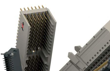

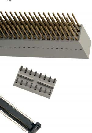

341 E
V.6-17 Colibri for COM Express
 V.6-17 Colibri for COM Express 0.5 mm SMT Board-to-Board Connector System Introduction Colibri 0.5 mm SMT for 10+ Gbit/s Applications Connectors for COM Express Key Features: Termination ept s Colibri
Colibri for COM Express. 0.5 mm SMT Board-to-Board Connector System
 V. 01/18 for COM Express 0.5 mm SMT Board-to-Board Connector System Singel 3 B-2550 Kontich Belgium Tel. +32 (0)3 458 30 33 info@alcom.be www.alcom.be Rivium 1e straat 52 2909 LE Capelle aan den Ijssel
V.5/17. Connectors. product overview. Edition 5
 V.5/17 Connectors product overview Edition 5 Editorial Good connections bear a name: ept Thomas Bernhard Claus Guglhör Guglhör Guglhör ept designs, produces and distributes electronic connectors for highquality
TCA connectors. ept GmbH & Co. KG I Phone +49 (0) 88 61/ I Fax +49 (0) 88 61/55 07 I I
 88 61/ I Fax +49 (0) 88 61/55 07 I I") 10 ept GmbH & Co. KG I Phone +49 (0) 88 61/25 01 0 I Fax +49 (0) 88 61/55 07 I E-mail sales@ept.de I www.ept.de 11 Definitions AdvancedTCA /MicroTCA To give consideration to increasing data traffic and
10 ept GmbH & Co. KG I Phone +49 (0) 88 61/25 01 0 I Fax +49 (0) 88 61/55 07 I E-mail sales@ept.de I www.ept.de 11 Definitions AdvancedTCA /MicroTCA To give consideration to increasing data traffic and
PC/104, PC/104-Plus %ASYç3TACKINGçWITHç0RESS lt 160
 160 PC/104, Contents Introduction 162 Overview 163 The Standard 164 166 167 PC/104 168 170 Accessories: 173 161 Introduction PC/104, Highest Quality for Established Form Factor PC/104 and is a standard
One mm SMT for Board-to-Board
 E L E C T R O N I C C O N N E C T O R S One27 mm SMT for Board-to-Board 30 ept GmbH I Tel. +49 (0) 88 61 / 25 01 0 I Fax +49 (0) 88 61 / 55 07 I E-Mail sales@ept.de I www.ept.de Contents Introduction 32
hm connectors ept GmbH & Co. KG I Phone +49 (0) 88 61/ I Fax +49 (0) 88 61/55 07 I I
 88 61/ I Fax +49 (0) 88 61/55 07 I I") 26 Definitions 28 Technical specifications 29 Electrical properties 30 Cross talk 31 Hole specifications 32 System modularity 33 Pin lengths 34 Notes 35 hm 2.0 type A 36 hm 2.0 type B25 38 hm 2.0 type
26 Definitions 28 Technical specifications 29 Electrical properties 30 Cross talk 31 Hole specifications 32 System modularity 33 Pin lengths 34 Notes 35 hm 2.0 type A 36 hm 2.0 type B25 38 hm 2.0 type
Right angle press-fit D-Sub connectors
 Right angle press-fit D-Sub connectors Version in Standard and in Eurostyle General The new generation of right angle D-Sub connectors with press-fit termination of the TMC series are according to DIN
Extract from new. Device Connectivity catalogue. HARTING har-flex. People Power Partnership
 Extract from new Device Connectivity catalogue HARTING har-flex People Power Partnership . har-flex CONNECTORS The continuous scalability by an even number of contacts, i.e. from 6 to 100, of the HARTING
Connectors DIN 41612/IEC
 Connectors DIN 41612/IEC 60603-2 and completions General information The DIN 41612/IEC 60603-2 connector family consists of 13 basic sizes and many complementary versions. It was developed for use in 19"
High-density multi-pin connectors
 High-density multi-pin connectors Mating and mounting conditions to DIN 41612/IEC 60603-2 General With the ever increasing miniaturization and higher packaging densities in highly integrated circuits there
IDC Assembly (depends on cable) -55/125 C. IDC Assembly (depends on cable) By ambient temperature: 20 C 1,2 A 70 C 0,9 A 100 C 0,6 A
 -55/125 C. IDC Assembly (depends on cable) By ambient temperature: 20 C 1,2 A 70 C 0,9 A 100 C 0,6 A") mm Connectors Surface Mount Technology, Solderless Pressfit, IDC Electrical And Mechanical Characteristics Number of Pins Technical data Climate Category Bearing and operating temperature area Current
mm Connectors Surface Mount Technology, Solderless Pressfit, IDC Electrical And Mechanical Characteristics Number of Pins Technical data Climate Category Bearing and operating temperature area Current
VMEbus systems System description Technical characteristics System description
 Directory chapter 06 / inverse Page VMEbus systems................................................ 06.02 System description.............................................. 06.03 Technical characteristics..........................................
ODU PCB Connectors ODU MINI-CARD.
 ODU PC Connectors ODU MINI-CRD Contents Chapter From page 1 Female headers, Series 525 3 2 Pin headers, Series 515 8 Description: With the most compact dimensions and maximum performance, ODU MINI-CRD
High-density multi-pin connectors
 High-density multi-pin connectors Mating and mounting conditions to DIN 41612/IEC 60603-2 General With the ever increasing miniaturization and higher packaging densities in highly integrated circuits there
2.54 mm Single Row Connector (SRC) MaxiBridge.
 MaxiBridge.") 2.54 mm Single Row Connector (SRC) www.erni.com Katalog Catalog D E 074591 074518 02/10 Ausgabe 3, 03/05 Edition www.erni.com 7 1 www.erni.com Catalog E 074591 02/10 Edition 7 Table of Contents General..............................................................................................2
2.54 mm Single Row Connector (SRC) www.erni.com Katalog Catalog D E 074591 074518 02/10 Ausgabe 3, 03/05 Edition www.erni.com 7 1 www.erni.com Catalog E 074591 02/10 Edition 7 Table of Contents General..............................................................................................2
09. DIN Connectors
 . Connectors Connectors that comply with have been in use for years for both board-to-board applications and cable-to-board applications. Their robustness and universality are legendary. The classic signal
D-Sub SEaled subminiature D connectors, 2.54 mm pitch
 SE D-Sub SEaled subminiature D connectors, 2.54 mm pitch Page Technical characteristics.......................................... 02 IP 67 versions with turned solder cups......... 04 IP 67 versions with
Connectors DIN 41612/IEC
 Connectors DIN 41612/IEC 60603-2 and completions ERNI-electronic components quality assessed according to CECC 75101-801 2 www.erni.com/contact/ General information The DIN 41612/IEC 60603-2 connector
ERNIPRESS Trapezoidal-Connectors Series TMC
 ERNIPRESS Trapezoidal-Connectors Series TMC Subminiatur-D Connectors to DIN 41 652/IEC 807-3 with Press-fit zone General Solderless press-in technology for connectors in bus systems permits rationalized
07. har-link Interface Connectors
 . Interface Connectors The highest data rates in combination with perfect shielding characterize the connector. This way data can be passed on optimally within the control cabinet. The locking mechanism
Han PCB termination. Han-Fast Lock PCB adapter for Han DD PCB adapter for Han DDD module
 Han termination Contents Page Han-Fast Lock... 20.11 adapter for Han DD... 20.13 adapter for Han DDD module... 20.16 adapter for Han 40 A Axial module... 20.18 adapter for Han E... 20.20 adapter for Han
09. DIN CONNECTORS
 . 41 612 CONNECTORS Connectors that comply with 41 612 have been in use for years for both board-to-board applications and cable-to-board applications. Their robustness and universality are legendary.
2.54 mm Single Row Connector (SRC) MaxiBridge.
 MaxiBridge.") 2.54 mm Single Row Connector (SRC) www.erni.com Katalog Catalog D E 074593 074518 Ausgabe 02/10 3, 03/05 www.erni.com Edition 7 1 www.erni.com Catalog E 074593 02/10 Edition 7 Table of Contents General...2
2.54 mm Single Row Connector (SRC) www.erni.com Katalog Catalog D E 074593 074518 Ausgabe 02/10 3, 03/05 www.erni.com Edition 7 1 www.erni.com Catalog E 074593 02/10 Edition 7 Table of Contents General...2
2.54mm Board to Cable Connectors Series LPV IEC Catalog E /05 Edition 1
 2.54mm Board to Cable Connectors Series LPV IEC 60603-13 www.erni.com Catalog E 074546 05/05 Edition 1 www.erni.com Catalog E 074546 05/05 Edition 1 Table Of Contents Board to Cable Connectors Series LPV.....................................................................2
2.54 mm Single Row Connector (SRC) MaxiBridge.
 MaxiBridge.") 2.54 mm Single Row Connector (SRC) www.erni.com Katalog Catalog D E 074593 074518 10/08 Ausgabe 3, 03/05 Edition www.erni.com 4 1 www.erni.com Catalog E 074593 10/08 Edition 4 Table of Contents General..............................................................................................2
2.54 mm Single Row Connector (SRC) www.erni.com Katalog Catalog D E 074593 074518 10/08 Ausgabe 3, 03/05 Edition www.erni.com 4 1 www.erni.com Catalog E 074593 10/08 Edition 4 Table of Contents General..............................................................................................2
BOARD/WIRE-TO-BOARD CONNECTORS MINITEK UNSHROUDED VERTICAL HEADERS
 BOARD/WIRE-TO-BOARD CONNECTORS MINITEK UNSHROUDED VERTICAL HEADERS MINITEK UNSHROUDED VERTICAL HEADERS TECHNICAL INFORMATION MATERIALS Housing: High temperature, black thermoplastic Flammability rating:
Velox. High-Speed Backplane Connectors for VPX
 High-Speed Backplane onnectors for VPX ontents Introduction 3 Technical Specifications 5 Hole Specifications 6 Velox High-Speed Backplane-onnector 7 Accessories: Guidings 9 2 ept GmbH I Tel. +49 (0) 88
INTERCONNECT SOLUTIONS
 INTERCONNECT SOLUTIONS Products Overview Connect with Us... Experience Makes the Difference Who We Are We have been designing and manufacturing interconnect products for over 40 years. Today we supply
M20 and M22. (2.54mm and 2.00mm pitch)
") M20 and M22 (2.54mm and 2.00mm pitch) M20 and M22 Connectors Great Design Flexibility Today s electronics and PCB designers are faced with many connector challenges, including applications with increased
M20 and M22 (2.54mm and 2.00mm pitch) M20 and M22 Connectors Great Design Flexibility Today s electronics and PCB designers are faced with many connector challenges, including applications with increased
Connector with mm square contacts DIC- 131 DIC- DIC- 129 DIC- 128A DIC- 129A AC 500V AC 1000V. 20 milliohms or less
 mm Pitch Connectors DIC series mm Pitch Connectors Outline The DIC series provides various connectors for switching between circuits on PCB in combination with various male connectors, for various-pattern
BOARD-TO-BOARD HEADERS & RECEPTACLES
 TE Connectivity: Every Connection Counts 2015 TE Connectivity Ltd. family of companies. All Rights Reserved CONNECTORS BOARD-TO-BOARD HEADERS & RECEPTACLES TE CONNECTIVITY (TE) MICTOR RECEPT ASSY, 38 POS.
07. har-link INTERFACE CONNECTORS
 . INTERFACE CONNECTORS The highest data rates in combination with perfect shielding characterize the connector. This way data can be passed on optimally within the control cabinet. The locking mechanism
ERNIPRESS. DIN 41612/IEC Press-fit connectors catalog E /02 Edition 4
 ERNIPRESS DIN 41612/IEC 60603-2 Press-fit connectors 132 www.erni.com/contact/ Benefits of ERNIPRESS Gas-tight, corrosionproof and mechanically strong connection No soldering errors No terminal stress
Catalog C-035 Rev. C
 Catalog C-035 Rev. C P O S I T R O N I C I N D U S T R I E S Today, some customer applications have requirements for high bandwidth transfer between VMEbus cards. Requirements which even the most updated
RIBBON CABLE CONNECTORS
 TE Connectivity: Every Connection Counts 2015 TE Connectivity Ltd. family of companies. All Rights Reserved CONNECTORS RIBBON CABLE CONNECTORS TE CONNECTIVITY (TE) IDC LOW PRO HDR 30P VERT LG LA AMP-LATCH
MicroStac. 0.8 mm Connectors ED Full-Scale MicroStac 50 Pins Catalog E
 MicroStac 0.8 mm Connectors ED. 12 11.2016 Full-Scale MicroStac 50 Pins Catalog E 074521 MEZZANIN CONNECTOR SYSTEM GENERAL MicroStac singleand dual-row versions MicroStac connector series features hermaphroditic
2.54 mm STL Pin Headers and Sockets. Catalog E /07 Edition 1
 and Sockets www.erni.com Catalog E 074569 02/07 Edition 1 www.erni.com www.erni.com Catalog E 074569 02/07 Edition 1 www.erni.com General If you need to connect two PCBs which are arranged on top of each
QUICKIE SHROUDED HEADERS LOW PROFILE
 BOARD/WIRE-TO-BOARD CONNECTORS QUICKIE SHROUDED HEADERS LOW PROFILE FEATURES & BENEFITS Recessed pins assure proper alignment and eliminate damage during mating End windows for latching with IDC receptacle
07. har-link Interface Connectors
 . Interface Connectors The highest data rates in combination with perfect shielding characterize the connector. This way data can be passed on optimally within the control cabinet. The locking mechanism
MicroSpeed mm High Speed Mezzanine Connector System for 10 GBit/s. Catalog E /08 Edition 1
 MicroSpeed - 1.0 mm High Speed Mezzanine www.erni.com Catalog E 074574 03/08 Edition 1 www.erni.com Catalog E 074574 03/08 Edition 1 Table of Contents General..............................................................................................2
Male header, 100% protected against mismating, (1 x 1) mm straight solder pins Pin spacing 3.5 mm 3.81 mm. light gray <_ 8,5_> 3,5 1x1 <_ 9,3_>
 mm straight solder pins Pin spacing 3.5 mm 3.81 mm. light gray <_ 8,5_> 3,5 1x1 <_ 9,3_>") 96 Male Headers with Solder Pins; Double-Deck Male Headers with Solder Pins, Pin Spacing 3.5 mm and 3.81 mm 160 V/.5 kv/ 300 V, 10 A U 10 A 300 V, 10 A 160 V/.5 kv/ 300 V, 10 A U 10 A 300 V, 10 A 160 V/.5
96 Male Headers with Solder Pins; Double-Deck Male Headers with Solder Pins, Pin Spacing 3.5 mm and 3.81 mm 160 V/.5 kv/ 300 V, 10 A U 10 A 300 V, 10 A 160 V/.5 kv/ 300 V, 10 A U 10 A 300 V, 10 A 160 V/.5
2.0 Connector System IEC Definition of Terms Contact length of the rear and front mating area Connector according to IEC
 Definition of Terms Connector according to The hardmetric connector system ept-hm 2.0 was developed according to the international standard. As a result, a worldwide standard for the combination of PCBs
BOARD-TO-BOARD HEADERS & RECEPTACLES
 TE Connectivity: Every Connection Counts 2015 TE Connectivity Ltd. family of companies. All Rights Reserved CONNECTORS BOARD-TO-BOARD HEADERS & RECEPTACLES TE CONNECTIVITY (TE) MICT,REC,038,ASY,.025,TAPE,CAP
RACON short-travel keyswitches
 General data short-travel keyswitches with sealed contact system and distinct key click, excellent switching reliability. For use under an overlay or with RK 90 keycaps. Print and SMD versions available
PC/104, PC/104 Plus Specification
 PC/104, PC/104 Plus Specification Industry Standard bus connection systems, typically used on embedded PC applications. Designed for oard-to-oard stacking with a common bus. PC/104 Connectors mm pitch
MicroSpeed Power Modules.
 MicroSpeed Power Modules www.erni.com Katalog Catalog D E 074587 074518 09/08 Ausgabe 3, 03/05 Edition www.erni.com 1 1 www.erni.com Catalog E 074587 09/08 Edition 1 Table of Contents General..............................................................................................2
SMC mm Connectors. Ed Full-scale SMC 50 Pins Catalog E
 SMC 1.27 mm Connectors Ed. 08 09.2014 Full-scale SMC 50 Pins Catalog E 074473 DUAL ROW CONNECTOR GENERAL SMC: Connectors for all applications Small Grid, Big Possibilities Limited space and high performance
1.27 mm SRC Single Row Connector MiniBridge Cable System. Catalog E /06 Edition 1
 1.27 mm SRC Single Row Connector MiniBridge Cable System www.erni.com Catalog E 074560 10/06 Edition 1 www.erni.com Catalog E 074560 10/06 Edition 1 1.27 mm SRC Single Row Connector MiniBridge Cable System
PCI Express Right Angle Connectors
 PCI Express Right Angle Connectors ED. 01 09.2015 Original Size PCI Express Right Angle Connector Catalog E 074641 DESCRIPTION GENERAL Right Angle Connectors These card edge connectors are designed to
MicroStac 0.8 mm Mezzanine Connector System. Catalog E /09 Edition 9
 MicroStac 0.8 mm Mezzanine Connector System www.erni.com Catalog E 074521 04/09 Edition 9 www.erni.com Catalog E 074521 04/09 Edition 9 Table of Contents Applications...........................................................................................2
Directory chapter 05. D-Sub Filter subminiature D connectors, 2.54 mm pitch
 F Directory chapter 05 D-Sub Filter subminiature D connectors, 2.54 mm pitch New Page General information.............................................. 05.02 Technical characteristics..........................................
MicroStac 0.8 mm Mezzanine Connector System. Catalog E /09 Edition 10
 MicroStac 0.8 mm Mezzanine Connector System www.erni.com Catalog E 074521 04/09 Edition 10 www.erni.com Catalog E 074521 04/09 Edition 10 Table of Contents Applications....2 Technical Features....3 Mating
CompactPCI PowerConnector
 CompactPCI PowerConnector Table of Contents 1 Introduction............................................................. 2 Product Features......................................................... 3 Performance
PowerElements. powered by BLUEcontact Solutions. Tel.: (+34) Fax: (+34)
 Fax: (+34)") powered by BLUEcontact Solutions ED. 02 09.2014 Original size PowerElement male thread M5 Catalog E 074634 BLUEcontact Solutions GENERAL PowerElements angled, full pin population, with and without threads
powered by BLUEcontact Solutions ED. 02 09.2014 Original size PowerElement male thread M5 Catalog E 074634 BLUEcontact Solutions GENERAL PowerElements angled, full pin population, with and without threads
0.4 mm Pitch, Horizontal Mating, Board-to-Micro-Coaxial Cable Connector
 0.4 mm Pitch, Horizontal Mating, Board-to-Micro-Coaxial Cable Connector DF81 Series Enhanced shielding capability Grounding connection between plug connector and receptacle connector 30 contacts: 5 locations
Data sheet. OMNIMATE Signal - series B2L/S2L row S2L-SMT 3.50/08/180G 3.5SN BK BX
 OMNIMATE Signal - series /S2L 3.50-2-row High-temperature-resistant, straight, 2-tier male connector for all common soldering methods. Optimised for automatic assembly. Packed in box or tape. 3.2 mm solder
Technical data: Pin Spacing
 282 Female Connectors, Double-Row Pin Spacing: 3.5 mm Universal connection for all conductor types Unique, compact, double-row connector system for conductor cross sections up to 1.5 mm 2 High-density,
Molex s family of high-speed Micro SAS Connectors featuring the Dual-stack Receptacle with Pin Cover
 Design-enhanced Micro SAS connectors now include dual-drive stacked receptacles with an integrated ground plane and a protective pin cover for greater reliability in compact storage applications Molex
DUBOX SHUNTS BOARD/WIRE-TO-BOARD CONNECTORS FEATURES & BENEFITS. Dual-beam contacts for added reliability
 BOARD/WIRE-TO-BOARD CONNECTORS DUBOX SHUNTS FEATURES & BENEFITS Dual-beam contacts for added reliability Slotted cutout in low profile housing simplifies electrical testing Side-by-side and end-to-end
MicroSpeed Right Angle Blind Mate Connectors
 ERNI has expanded its portfolio of high-speed Mezzanine connectors with the introduction of a right angle MicroSpeed 10 Gbit/s connector. At present, customers can choose from a wide range of connector
MicroStac 0.8 mm Mezzanine Connector System. Catalog E /08 Edition 8
 MicroStac 0.8 mm Mezzanine Connector System www.erni.com Catalog E 074521 02/08 Edition 8 www.erni.com Catalog E 074521 02/08 Edition 8 Table of Contents Applications...........................................................................................2
12. TCA Connectors. Application profile:
 . Connectors The connectors have been specifically developed for the next generation of telecom, medical and industrial applications. The compact connector allows the transmission of highest data rates.
Han R 23. Circular Connector. Certified acc. to DIN EN ISO 9001 in design/ development, production, installation and servicing.
 Circular Connector Certified acc to DIN EN ISO 9001 in design/ development, production, installation and servicing Data Sheet 0039-4 Circular Connectors Features Size R 23 Outer diameter 26 mm High contact
HARTING. Interface Connectors. People Power Partnership
 11 5 HARTING Interface Connectors People Power Partnership Directory chapter 00 Modular metric high speed connectors, 2.0 mm pitch Page connector system general information......................... 00.04
COMMUNICATIONS, DATA, CONSUMER DIVISION DIN Selector Guide. PCB Connectors
 COMMUNICATIONS, DATA, CONSUMER DIVISION DIN 41612 Selector Guide PCB Connectors FCI: SETTING THE STANDARD FOR CONNECTORS With operations in 30 countries, FCI is a leading manufacturer of connectors. Our
USB Type-C Connector. Overview. Features. CX Series. 1. Easy mating due to the reversible form factor
 USB Type-C Connector CX Series Overview Note: Please contact us for TID acquisition status of each product. The CX series connector conforms to the next-generation USB standard USB Type-C. It is expected
Accessories Cassette Style Mating Connectors
 Description All 19" cassette style converters are equipped with either H11, H15, H15S4, or H15S2 male connectors. Mating female connectors are available as accessories. The four H- type connector versions
Milli-Grid 2.00mm (0.79 ) Pitch. Interconnect System for Complete Design Flexibility
 Pitch. Interconnect System for Complete Design Flexibility") Milli-Grid for Complete Design Flexibility Milli-Grid 50394, 87396 Crimp Terminal 5110, 78045 Receptacle Crimp Housing 87568 IDT Receptacle 87569 IDT Strain Relief 87831, 78246 Through-Hole 87832 SMT 87833,
Milli-Grid for Complete Design Flexibility Milli-Grid 50394, 87396 Crimp Terminal 5110, 78045 Receptacle Crimp Housing 87568 IDT Receptacle 87569 IDT Strain Relief 87831, 78246 Through-Hole 87832 SMT 87833,
1.27 mm SMC Board-to-Board Adapter.
 1.27 mm SMC Board-to-Board Adapter www.erni.com Katalog Catalog D E 07518 07582 0/09 Ausgabe 3, 03/05 Edition www.erni.com 2 1 www.erni.com Catalog E 07582 0/09 Edition 2 Table of Contents General..............................................................................................2
onlinecomponents.com
 Power entry modules without line filter Felcom 64 IEC Appliance Inlet C14 with modular extended Components Plug removal necessary for fuse replacement 6421.005X.XX Appliance inlet Appliance outlet Snap-In
1.27 mm SMC Board-on IDC Cable Connectors.
 1.27 mm SMC Board-on IDC Cable Connectors www.erni.com Katalog Catalog D E 074518 074496 Ausgabe 02/08 3, 03/05 Edition www.erni.com 3 1 www.erni.com Catalog E 074496 02/08 Edition 3 Features Number of
PC Board Sockets. Specifications SOCKETS. Surface Mount, Single Piece construction. Throughboard, Two Piece construction. Materials.
 Sockets Contents SMT PCB Sockets Sockets For Ø0.5mm Pin Sockets For Ø0.8mm Pin Sockets For Ø1mm Pin Sockets For Ø2mm Pin Test Sockets IC Socket Strip Dual Row IC Socket Surface Mount, Single Piece construction
PC 104 and PC 104 plus-connectors. Technology in connectors
 PC 104 and PC 104 plus-connectors Technology in connectors Reliable Connectors for reliable Systems: CONEC PC/104 and PC/104plus- Since the beginning of the PC/104 era in 1992, inaugurated by publication
EXTreme Guardian Power Connector System
 Exceed high-current and reliability requirements in topend server and high-power applications with Molex s compact,, providing EMI/RFI shielding, overmolding and discretewire options for design flexibility
Applications
 Han PCB adapter Contents Page Technical characteristics PCB adapter for Han DD... 20.02 Han DD Inserts with PCB adapter... 20.03 Technical characteristics PCB adapter for Han E... 20.04 Han E Inserts with
Modular Connector System with High Power, Signal, Fibre-Optic, Coaxial Contacts and Pneumatic Valves
 Modular Connector System with High Power, Signal, Fibre-Optic, Coaxial Contacts and Pneumatic Valves 2 rue René Laennec 51500 Taissy France Fax: 03 26 85 19 08, Tel : 03 26 82 49 29 E-mail:hvssystem@hvssystem.com
Accessories Cassette Style Mating Connectors
 Description All 19" cassette style converters are equipped with either H11-, H15-, H15S4, or H15S2 male connectors. Mating female connectors are available as accessories. The four H- type connector versions
MicroSpeed 1.0 mm High Speed Connectors
 MicroSpeed 1.0 mm High Speed Connectors ED. 02 05.2015 Full-Scale MicroSpeed 50 Pins Catalog E 074574 MicroSpeed - High-Speed Connectors HIGH-SPEED. INTERCONNECT. SOLUTIONS. GENERAL MicroSpeed - the most
1.27 mm SRC Single Row Connector MiniBridge Cable System. Catalog E /09 Edition 5
 Single Row Connector MiniBridge Cable System www.erni.com Catalog E 074560 02/09 Edition 5 www.erni.com 2 Catalog E 074560 Catalog 10/06 E 074560 02/09 Edition 1 Edition www.erni.com 5 Single Row Connector
HARTING. Coaxial and Metric Connectors. People Power Partnership
 33 7 HARTING Coaxial and Metric Connectors People Power Partnership Quality Connections Worldwide HARTING was founded in 1945 by the family that still owns the company. Its headquarters are situated in
EPIC Circular Connectors CIRCON M23 Series
 The M3 connectors have many inherent features which offer application advantages and provide significant benefits for the customer. These features make it one of the most application friendly connectors
SEPTEMBER C.CS.1000 / GB
 SEPTEMBER 2005 - C.CS.1000 / GB C R I M P F L E X C O N N E C T O R S CRIMPFLEX connectors TECHNICAL DATA MATERIAL Phosphor bronze MALE SOLDER TAB PLATING The standard connector is tin plated (thickness
Dubox Product Presentation
 Product Presentation Basics Portfolio Agenda 1. Value Proposition 2. Product Overview 3. Product Specifications 4. Features & Benefits 5. Part Numbers 6. Markets & Applications 7. Marcomm Collaterals Product
D-SUBMINIATURE PIN-IN-PASTE CONNECTORS
 INPUT/OUTPUT CONNECTORS D-SUBMINIATURE PIN-IN-PASTE CONNECTORS OVERVIEW The D-Subminiature connectors are one of the most popular I/O solutions, addressing segments such as Telecommunications, Industrial,
USB, MINI USB, MICRO USB FIREWIRE & MINI FIREWIRE UNIVERSAL SERIAL BUS &
 INTRODUCTION: Adam Tech USB, Mini USB & Micro USB (Universal Serial Bus) and IEEE 1394 (Firewire) Series connectors are a complete line of shielded, hot pluggable, high speed I/O interface connectors available
ERNI MicroStac. Catalog E /05 Edition 5
 ERNI MicroStac www.erni.com www.erni.com 2 www.erni.com/contact/ Catalog E 074505 01/02 Edition 3 Table of Contents Applications...........................................................................................
ERNI MicroStac. Catalog E /06 Edition 6
 ERNI MicroStac www.erni.com Catalog E 074521 07/06 Edition 6 www.erni.com 2 www.erni.com/contact/ Catalog E 074505 01/02 Edition 3 Table of Contents Applications...........................................................................................
ERmet ZDplus.
 www.erni.com Katalog Catalog D E XXXXXX 07458 Ausgabe 09/3 3, 03/05 www.erni.com Edition 4 www.erni.com Catalog E XXXXXX 09/3 Edition 4 The ERmet ZDplus connector is an enhancement of the ERmet ZD family.
RIBBON CABLE CONNECTORS
 TE Connectivity: Every Connection Counts 2015 TE Connectivity Ltd. family of companies. All Rights Reserved CONNECTORS RIBBON CABLE CONNECTORS TE CONNECTIVITY (TE) A/L UNIV HDR 14P VERT AMP-LATCH Universal
USB 2.0 Standard Connectors
 USB 2.0 Standard Connectors UX Series Meets requirements of USB 2.0 Standard USB 2.0 certified Features 1. Compatible to USB 2.0 Standard The UX series connectors are certified by a certification organization
Operating voltages up to 40 kvdc Operating current up to 30 Amps Advanced contact technology Silver plated and gold plated contacts available High
 Operating voltages up to 40 kvdc Operating current up to 30 Amps Advanced contact technology Silver plated and contacts available High performance insulation material General characteristics and technical
USB, MINI USB, MICRO USB FIREWIRE & MINI FIREWIRE UNIVERSAL SERIAL BUS &
 INTRODUCTION: Adam Tech USB, Mini USB & Micro USB (Universal Serial Bus) and IEEE 1394 (Firewire) Series connectors are a complete line of shielded, hot pluggable, high speed I/O interface connectors available
ODU DOCK and ODU ROB. Connectors for Docking and Robot Systems.
 and ODU ROB Connectors for Docking and Robot Systems Robust Circular Connectors and ROB Applications Industrial robots Tool change and depot systems Cable connections for robot systems Test equipment Features
M12 PCB-Connectors 90 Angled. Catalog E /14 Edition 4
 M12 PCB-Connectors 90 Angled www.erni.com Catalog E 074617 06/14 Edition 4 Table of Content General...3 Assembly and Solder Recommendations...5 Dimensions and Assembly Recommendation for Standard M12 Male
CRIMPFLEX connectors for flexible circuits
 CRIMPFLEX connectors for flexible circuits CRIMPFLEX CONNECTORS Technical data...3 CRIMPFLEX CRIMPING Description...4 MALE SOLDER TABS Solder tabs environment...5 Standard short male solder tab...6 Standard
USB, MINI USB, MICRO USB FIREWIRE & MINI FIREWIRE UNIVERSAL SERIAL BUS &
 INTRODUCTION: Adam Tech USB, Mini USB & Micro USB (Universal Serial Bus) and IEEE 1394 (Firewire) Series connectors are a complete line of shielded, hot pluggable, high speed I/O interface connectors available
Item No.: /
 mounting adapter also for DIN 35 rail; % protected against mismating; Plate thickness 06x12 mm; Male connector; with snap-in mounting foot; 4-pole; pin spacing 35 mm / 0138 in; with 209-137 mounting adapter
Data sheet... OMNIMATE Power - series BL/SL 7.62HP BLZ 7.62HP/04/180LR SN BK BX
 Power on board #96 100% safety, 100% integration, 100% cost-effectiveness: The compact and efficient solution for UL-600V applications in the lower performance range (up to 12 kva). 29 A at 400V (IEC)
Accessories Cassette Style Mating Connectors H11, H15, H15S2, H15S4
 Description All 19" cassette style converters are equipped with either H11-, H15-, H15S4, or H15S2 male connectors. Mating female connectors are available as accessories. The four H-type connector versions