Downloaded from Elcodis.com electronic components distributor
|
|
|
- Norman Webster
- 5 years ago
- Views:
Transcription
1
2
3 CONTENTS LV24-33A KEY FEATURES 4 CONNECTING THE SYSTEM 5 INTRODUCTION 6 Switches and Jumpers 7 MCU Sockets 8 Power Supply 10 On-board USB 2.0 Programmer 11 RS-232 Communication Circuit 12 LEDs 14 Push Buttons 15 2x16 Character LCD 16 Graphic LCD 17 Touch Panel 18 A/D Converter Test Inputs 19 Direct Port Access Connectors 20 Multimedia Card (MMC/SD) 21
 slot; 7. LCD 2x16 connector; 8. LCD contrast potentiometer; 9. A/D converter test input; 10.")
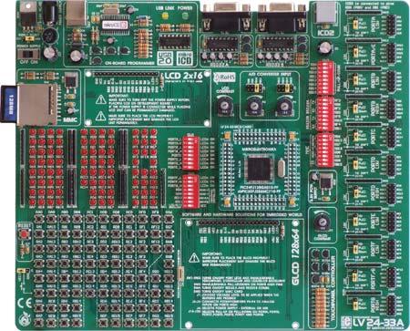
4 4 LV24-33A KEY FEATURES 1. External power supply 8v-16v AC/DC; 2. On-board USB 2.0 programmer; 3. RS-232 communication ports; 4. ICD2 connector; 5. Pull-up/pull-down jumper; 6. Multimedia card (MMC/SD) slot; 7. LCD 2x16 connector; 8. LCD contrast potentiometer; 9. A/D converter test input; 10. DIP switches SW3-SW5 used to enable pull-up/down on PORTB and RS232 and MMC communication ; 11. LEDs showing MCU pins logic state; 12. DIP switches SW1 and SW2 used to enable LED s on ports and touch panel controller; pin MCU card with SMD chip soldered on; V power supply; 15. Reset button circuit; 16. High/low state pin selector; 17. Push buttons; 18. Touch panel connector; 19. GLCD connector; 20. GLCD contrast potentiometer; 21. Touch panel controller; 22. 8x10K resistor network; and 23. Direct port access connector.
5 CONNECTING THE SYSTEM 5 Apart from this manual, the development system box contains development system, product CD, USB cable, RS232 cable and Installing USB drivers manual. In order to use the LV24-33A properly, it is necessary to go through the following steps: Step no.1 Step no.2 Step no.3 Step no.4 Take the development system and product CD out of the box. Insert the product CD into CD drive. Please, do not connect the development system to a PC yet. Install LV24-33 programmer software to enable a program to be transferred from PC to the microcontroller chip. For detailed installation instructions refer to the ' LvPICflash programmer' manual. Install USB drivers on your PC to enable programmer's hardware to operate properly on the LV24-33A board. For detailed installation instructions refer to the 'Installing USB drivers' manual. Connect the LV24-33A to PC using USB cable. Please use one of USB ports on the back of the PC as they are directly connected to the computer motherboard. The first time you switch the LV24-33A on, your PC will automatically detect a new hardware. You will be immediately prompted whether Windows should search for new drivers update or not. Select the option 'No, not this time' and click 'Next'. Another window appears, click 'Next' and the operating system will automatically find the drivers. Click 'Finish' to complete this process and run LvPICflash.. CONNECTING THE SYSTEM After these four steps, your LV24-33A is successfully installed and ready for use. You can read a program from the chip or write another one into it. The product CD provides numerous simple program examples to make your first steps Easy....

6 6 INTRODUCTION INTRODUCTION The LV24-33A development system is a full-featured development board for Microchip microcontrollers. It is designed to allow students and engineers to easily test and explore the capabilities of these PIC microcontrollers. It also allows PIC microcontrollers to be interfaced with external circuits and a broad range of peripheral devices. The user can therefore concentrate on software development only. Figure 1 illustrates the LV24-33A development system. There are identification marks next to each component on a silkscreen, both on the top and bottom. These marks describe connections to the microcontroller, operation modes and provide other useful information so that there is almost no need for additional schematic. Figure 1 LV24-33A development board

7 SWITCHES 7 The LV24-33A development system features a number of peripheral devices. In order to enable them before programming, the appropriate jumpers or switches have to be properly set. For this system, switches are grouped in five DIP packages containing eight switches each. Figure 2 DIP switch SW3 Switches 1, 2, 3 and 4 are ON, whereas 5, 6, 7 and 8 are OFF DIP switch SW1 is used to enable/disable first eight LED groups for MCU ports; DIP switch SW2 is used to enable/disable the last three LED groups for MCU ports, touch panel controller and LCD/GLCD backlight; DIP switch SW3 is used to enable/disable pull-up/pull-down resistors on PORTB HIGH; DIP switch SW4 enables/disables Rx and Tx lines of RS232A and RS232B communication modules; and DIP switch SW5 is used to enable/disable MMC/SD (Multimedia Card) data lines. SWITCHES AND JUMPERS JUMPERS Similarly, jumpers are used to break or establish connection between two points. Under the plastic cover of a jumper, there is a metal contact which establishes connection when the jumper is placed over two pins. Jumper is commonly used as a selector between two possible connections via 3-pin connector. As illustrated in Figure 3, the middle connector pin can be connected to the left or right pin, depending on the jumper s position. Jumper is not placed and middle pin is unconnected. Jumper is placed on the right side connecting middle and right pin. Jumper is placed on the left side connecting middle and left pin. Figure 3 Jumper as a selector


8 8 MCU SOCKETS MCU SOCKETS The LV24-33A comes with a 100-pin PIC24FJ96GA010 microcontroller in TQFP package soldered on MCU card. The user can remove this card and fit another one with TQFP chip in 64, 80 or 100-pin package. Figure 4 MCU socket When placing MCU card in the LV24-33A MCU socket, it is necessary to follow the steps below: Step no. 1 If MCU card is already placed on the LV24-33A, it is necessary to remove it by pulling it up slowly. Step no. 2 Place another MCU card on the board. Note that label on the MCU card must be in the upper-left corner as labeled on the LV24-33A board. Step no. 3 When the MCU card is properly placed, push it down by applying pressure on all edges at the same time.
 connectors.")


9 The microcontroller pins are routed to various peripherals as illustrated in Figure 5. All ports have direct connections to Direct Port Access 2x5(10-pin) connectors. These connectors are typically used for connecting external peripherals to the board or as points for digital logic probe connecting. All ports are connected to LEDs and push-buttons, which allows you to easily test and monitor digital pins state. Some of the pins are connected to other peripherals such as DS1820 temperature sensor, RS- 232 communication module, RS-485 communication module, LCD, etc. For example RB9 pin is connected to LED, push button and other periperials on board as shovn on ilustration below: 9 MCU SOCKETS Figure 5 MCU system connection
 and external power supply (external AC/DC power adapter).")


10 10 POWER SUPPLY POWER SUPPLY The LV24-33A can use one out of two power supply sources - PC power supply over USB cable (by default) and external power supply (external AC/DC power adapter). When using power supply over USB cable, the jumper J4 should be set in the right-hand position. When using external power supply, the LV24-33A board produces +5V using LM7805 voltage regulator. The external power supply can be AC or DC, while power supply voltage ranges between 8V and 16V. Jumper J4 should be set in the left-hand position. Unlike other microcontrollers, this one needs 3.3V for its operation. This voltage is derived from 5V power supply using additional voltage regulator MC Figure 6 Power supply Figure 7 Power supply circuit diagram J4 in the left-hand position: system is powered from external AC/DC power adapter. J4 in the right-hand position: system is powered from PC over USB cable.

11 ON-BOARD USB 2.0 PROGRAMMER 11 There is no need to use external equipment during programming as the LV24-33A development system has its own on-board USB 2.0 programmer. All you need to do is to connect the system to PC using the USB cable. Then, load your program into the microcontroller via the LV24-33A programming software supplied with the LV24-33A board. Figure 8 USB 2.0 programmer ON-BOARD USB 2.0 PROGRAMMER Figure 9 USB 2.0 programmer circuit diagram Note: There is no need to reset MCU after programming because the programmer will reset it automatically.

12 12 RS-232 COMMUNICATION CIRCUIT RS-232 COMMUNICATION CIRCUIT RS-232 communication circuit enables point-to-point data transfer. It is commonly used in data acquisition applications to transfer data between the microcontroller and PC. Since the voltage levels of the microcontroller and PC are not directly compatible with each other, a level converter, such as MAX232, must be used. In order to provide more flexible system, the microcontroller is connected to MAX232 via DIP switch SW4. The first four switches of SW4 are used to connect Rx and Tx lines belonging to RS-232A to the microcontroller, whereas the last four switches are used to connect Rx and Tx lines belonging to RS-232B to the microcontroller. Figure 10 RS-232 communication ports
13 13 RS-232 COMMUNICATION CIRCUIT Figure 11 RS-232 communication circuit diagram

14 14 LEDs LEDS Light Emitting Diode (LEDs) are components most commonly used for displaying pin digital state. The LV24-33A has 85 LEDs connected to the microcontroller ports: PORTA_L, PORTA/E,PORTB_L, PORTB_H, PORTC, PORTD_L, PORTD_H, PORTE_L, PORTF_L, PORTF/G and PORTG_H. Figure 12 LEDs You can enable/disable port LEDs using the appropriate switch of the DIP switches SW1 and SW2 depending on the port you want to use. Figure 13 LEDs circuit diagram


15 PUSH BUTTONS 15 The LV24-33A has 85 push buttons used to provide digital inputs to the microcontroller ports. There is also one red push button that acts as a RESET button. Figure 15 illustrates connection between pushbuttons and PORTA low and reset button as well. There are another six ports which are not shown on this circuit diagram but are connected to push buttons the same way as PORTA low. Figure 14 Push buttons PUSH BUTTONS Figure 15 Push-buttons circuit diagram

16 16 2X16 CHARACTER LCD 2X16 CHARACTER LCD Figure 16 2x16 LCD in 4-bit mode A standard character LCD is probably most widely used data visualization component. It usually displays messages in two lines, containing up to 16 alphanumeric characters each. The character LCD communicates with the microcontroller via 4-bit data bus. Figure 17 illustrates its connection to the microcontroller. Figure 17 2x16 LCD circuit diagram Note: It is important to bear in mind that LCD should be placed or removed from the LV24-33A only after the power supply is switched off. Otherwise, it could be permanently damaged.


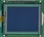
17 GRAPHIC LCD 17 A graphic LCD (GLCD) provides an advanced method for displaying visual messages. While a character LCD can display only alphanumeric characters, a GLCD can be used to display messages in the form of drawings and bitmaps. Most commonly used graphic LCD has a screen resolution of 128x64 pixels. The GLCD contrast can be adjusted using the potentiometer P2 placed in the bottom right corner of GLCD. Figure 18 GLCD GRAPHIC LCD Figure 19 GLCD circuit diagram Note: It is very important to bear in mind that GLCD should be placed or removed from the LV24-33A development board only after the power supply is switched off. Otherwise, it could be permanently damaged.


18 18 TOUCH PANEL TOUCH PANEL Touch panel is a thin, self-adhesive, transparent panel that could be placed over the screen of graphic LCD. It consists of two separate foils which form a sandwich structure. It is very sensitive to press so that even a soft touch causes some changes on the output signal. It is used in various user-friendly devices in combination with graphic LCD. Connector CN4 enables this device to be connected to on-board touch panel controller the active part of which consists of 5 discrete transistors. Four switches of the DIP switch SW2 enable or disable connection between this controller and RB8, RB9, RD10 and RD11 pins. Figure 20 Touch panel Figure 21 Touch panel controller Figure 22 Touch panel circuit diagram

19 A/D CONVERTER TEST INPUTS A/D conversion has a wide range of applications. The microcontroller takes an analog signal from its input pin and converts it into a digital value. Basically, it is possible to measure any analog signal that fits in the range acceptable by the microcontroller. As for the LV24-33A, this range is between 0 and 3.3V. Figure 23 A/D converter test inputs The LV24-33A development board has two potentiometers for demonstrating the operation of analog-to-digital converter (ADC). Both potentiometer outputs are in the range of 0 to 3.3V. These analog signals can be connected to two different analog input pins simultaneously. Jumper groups J2 and J3 are used for connecting potentiometers P3 and P4 to the appropriate MCU pins. 19 A/D CONVERTER TEST INPUTS Figure 24 A/D converter test inputs circuit diagram


20 20 DIRECT PORT ACCESS CONNECTORS DIRECT PORT ACCESS CONNECTORS All microcontroller input/output pins can be accessed via IDC10 connectors (2x5) placed along the right side of the board. For each microcontroller port there is one connector providing up to eight port pins and two additional pins connected to VCC and GND. Figure 26 Direct port access Figure 25 Flat cable connection Figure 27 Direct port access circuit diagram These connectors can be used to connect the system to external peripherals such as Serial Ethernet, Compact Flash, MMC/SD, ADC, DAC, CAN, RTC, RS-485 etc. If on-board and external peripherals use the same pins then on-board peripherals must be disconnected from the microcontroller by setting the appropriate jumpers. The connectors can also be used for attaching logic probes or other test equipment.

21 MULTIMEDIA CARD (MMC/SD) 21 MMC card is used as a storage media for portable devices. With MMC reader you can easily transfer data from MMC card to your computer. Microcontroller on the LV24-33A communicates with Multi Media Card via SPI communication. To enable MMC card you must turn on switches of the DIP switch SW5. By doing this, MMC s Chip Select (MMC-CS) and SPI communication lines (SCK, MISO and MOSI) are connected with the microcontroller. Figure 29 Figure 28 MMC/SD (multimedia card) circuit diagram MMC/SD (multimedia card) MULTIMEDIA CARD(MMC/SD) Precise voltage reference source (3.3V)
22 Very fast and flexible USB 2.0 programmer A/D converter test input USB communication External power supply 8-16 V AC/DC Choose between external and USB power supply. When using USB port, there is no need for external power supply. Jumper to select high/low state of the input pins when the button is pressed IDC10 port connector (5x2) for direct port access 2x16 LCD display 2x16 LCD display contrast potentiometer LEDs are connected to MCU pins and showing their state Touch panel controller LV24-33A supports microcontroller in TQFP packages Touch panel thin ribbon cable ICD2 connection Switch groups SW1-SW5 are used for enabling/disabling onboard components 3.3V power supply GLCD contrast potentiometer LV24-33A RS232 communication with selectable TX and RX GLCD with touch panel Buttons to activate pins high/low state Power supply ON/OFF switch MMC/SD card slot Reset circuit
23
24
CONTENTS. dspicpro4 KEY FEATURES 4 CONNECTING THE SYSTEM 5 INTRODUCTION 6
 CONTENTS dspicpro4 KEY FEATURES 4 CONNECTING THE SYSTEM 5 INTRODUCTION 6 Switches and Jumpers 7 MCU Sockets 8 Power Supply 10 On-Board USB 2.0 Programmer 11 MikroICD 12 RS-232 Communication Circuit 13
CONTENTS BIGAVR2 KEY FEATURES 4 CONNECTING THE SYSTEM 5 INTRODUCTION 6
 CONTENTS BIGAVR2 KEY FEATURES 4 CONNECTING THE SYSTEM 5 INTRODUCTION 6 Switches 7 Jumpers 8 MCU Sockets 9 Power Supply 11 On-board USB 2.0 Programmer 12 Oscillator 14 LEDs 15 Reset Circuit 17 Push-buttons
2 in 1. EasyAVR4 User s Manual AVR. MikroElektronika. Software and Hardware solutions for Embedded World
 SOFTWARE AND HARDWARE SOLUTIONS FOR THE EMBEDDED WORLD - Books - Compilers User s Manual 2 in 1 2.0 IN-CIRCUIT PROGRAMMER ATMEL AVR DEVELOPMENT BOARD With useful implemented peripherals, plentiful practical
BIGdsPIC6. Development System. User manual
 BIGdsPIC6 User manual All s development systems represent irreplaceable tools for programming and developing microcontroller-based devices. Carefully chosen components and the use of machines of the last
2 in 1. BigAVR User s Manual AVR. MikroElektronika. Software and Hardware solutions for Embedded World
 SOFTWARE AND HARDWARE SOLUTIONS FOR THE EMBEDDED WORLD - Books - Compilers User s Manual 2 in 1 USB 2.0 IN-CIRCUIT PROGRAMMER ATMEL AVR DEVELOPMENT BOARD With useful implemented peripherals, plentiful
BIG8051. Development system. User manual
 BIG8051 User manual All s development systems represent irreplaceable tools for programming and developing microcontroller-based devices. Carefully chosen components and the use of machines of the last
3 in 1 ICD. EASYdsPIC4 User s Manual. MikroElektronika. Software and Hardware solutions for Embedded World
 SOFTWARE AND HARDWARE SOLUTIONS FOR THE EMBEDDED WORLD - Books - Compilers EASYdsPIC4 User s Manual mikro 3 in 1 IN-CIRCUIT DEBUGGER MICROCHIP dspic DEVELOPMENT BOARD USB 2.0 IN-CIRCUIT PROGRAMMER With
EasyPIC5 Development System
 EasyPIC5 Development System Part No.: MPMICRO-PIC-Devel- EasyPIC5 Overview EasyPIC5 is a development system that supports over 120 8-, 14-, 18-, 20-, 28- and 40-pin PIC MCUs. EasyPIC5 allows PIC microcontrollers
Easy24-33 v6. Development System. User manual
 Easy24-33 v6 User manual All s development systems represent irreplaceable tools for programming and developing microcontroller-based devices. Carefully chosen components and the use of machines of the
EasyAVR6 Development System
 EasyAVR6 Development System Part No.: MPMICRO-AVR-Devel-EasyAVR6 Overview EasyAVR6 is a development system that supports a wide range of 8-, 14-, 20-, 28- and 40-pin AVR MCUs. EasyAVR6 allows AVR microcontrollers
DEVBOARD3 DATASHEET. 10Mbits Ethernet & SD card Development Board PIC18F67J60 MICROCHIP
 DEVBOARD3 DATASHEET 10Mbits Ethernet & SD card PIC18F67J60 MICROCHIP Version 1.0 - March 2009 DEVBOARD3 Version 1.0 March 2009 Page 1 of 7 The DEVBOARD3 is a proto-typing board used to quickly and easily
UNI-DS3. Development System. User manual
 All s development systems represent irreplaceable tools for programming and developing microcontroller-based devices. Carefully chosen components and the use of machines of the last generation for mounting
Pridgen Vermeer Robotics Xmega128 Manual
 Features: 12x PWM signals with 5V supply 8x A/D Inputs with 3.3V supply 2x RS 232 Terminals 1x SPI Interface 4x 8-bit Digital IO ports 3.3V Power Bus LCD Header (4-bit mode) Smart Power Connecter Power
Pridgen Vermeer Robotics ATmega128 Revision 0
 Features: 6x 8-bit I/O Ports 4x A/D Inputs 6x PWM Headers 2x RS 232 Terminals Power Bus LCD Header (4-bit mode) Smart Power Connecter Power Switch Header Power LED Debug LED Note: Some pins have multiple
EvB 4.3 v4 User s Guide
 EvB 4.3 v4 User s Guide Page 1 Contents Introduction...4 The EvB 4.3 v4 kit...5 Power supply...6 Programmer s connector...7 USB Port...8 RS485 Port...9 LED's...10 Pushbuttons...11 Potentiometers and Buzzer...12
PICado Alpha Development Board V1.0
 V1.0 Bluetooth Transceiver Module HC-05 Four onboard FET power output stage 34 freely assignable I/O pins ICSP interface 2015 Jan Ritschard, All rights reserved. V1.0 Table of Contents 1. Introduction...
ET-PIC 24 WEB-V1. o Central Processing Unit (CPU) o System. o nanowatt Power Managed Modes. o Analog Features
 o System. o nanowatt Power Managed Modes. o Analog Features") ET-PIC 24 WEB-V1 ET-PIC 24 WEB-V1 is PIC Board Microcontroller from Microchip that uses 16 Bit No.PIC24FJ128GA008 Microcontroller for processing data and develops board. The remarkable specification of
ET-PIC 24 WEB-V1 ET-PIC 24 WEB-V1 is PIC Board Microcontroller from Microchip that uses 16 Bit No.PIC24FJ128GA008 Microcontroller for processing data and develops board. The remarkable specification of
Breeze Board. Type A. User Manual.
 Breeze Board Type A User Manual www.dizzy.co.za Contents Introduction... 3 Overview Top... 4 Overview Bottom... 5 Getting Started (Amicus Compiler)... 6 Power Circuitry... 7 USB... 8 Microcontroller...
PVK40. User's manual. Feature Rich Development and Educational Kit for 40-pin Microchip PIC microcontrollers
 PVK40 User's manual Feature Rich Development and Educational Kit for 40-pin Microchip PIC microcontrollers CONTENTS PVK40 3 On-board peripherals: 3 Power supply 4 Microcontroller 4 Reset circuitry 4 Oscilator
SimPLC. User Manual.
 SimPLC User Manual www.dizzy.co.za Contents Introduction... 4 Overview Top... 5 Power Circuitry... 6 Microcontroller... 7 Real-Time Calendar and Clock (RTCC)... 7 Reset Button... 7 Oscillator Socket...
DEV16T. LCD Daughter board
 LCD Daughter board Table of Contents 1 Introduction...2 2 Features...3 3 Expansion Connectors...4 3.1 Daughter Board Connectors...4 4 LCD Display...5 5 Input Buttons S1 to S4...5 6 Buzzer...5 7 Connector
WICE-SPI Hardware Operation Manual
 WICE-SPI Hardware Operation Manual 1. Hardware Instruction 1. WICE-SPI processes data transmission, programming or emulation through USB 2.0 interface and does not need external power. 2. WICE-SPI is equipped
AVR Intermediate Development Board. Product Manual. Contents. 1) Overview 2) Features 3) Using the board 4) Troubleshooting and getting help
 Overview 2) Features 3) Using the board 4) Troubleshooting and getting help") AVR Intermediate Development Board Product Manual Contents 1) Overview 2) Features 3) Using the board 4) Troubleshooting and getting help 1. Overview 2. Features The board is built on a high quality FR-4(1.6
AVR Intermediate Development Board Product Manual Contents 1) Overview 2) Features 3) Using the board 4) Troubleshooting and getting help 1. Overview 2. Features The board is built on a high quality FR-4(1.6
Axiom Manufacturing. Users Manual. for PROJECT DEVELOPMENT BOARD AXM xiom anufacturing
 Axiom Manufacturing Users Manual for PROJECT DEVELOPMENT BOARD AXM-0295 xiom anufacturing 1999 2813 Industrial Ln. Garland, TX 75041 (972) 926-9303 FAX (972) 926-6063 support@axman.com Rev 1.0 web: http://www.axman.com
DIGI POT 3 click. PID: MIKROE 3016 Weight: 25 g
 DIGI POT 3 click PID: MIKROE 3016 Weight: 25 g DIGI POT 3 click is a versatile and feature-rich digital potentiometer click with 1024 steps and an internal non-volatile memory (EEMEM), which can be used
Display Real Time Clock (RTC) On LCD. Version 1.2. Aug Cytron Technologies Sdn. Bhd.
 On LCD. Version 1.2. Aug Cytron Technologies Sdn. Bhd.") Display Real Time Clock (RTC) On LCD PR12 Version 1.2 Aug 2008 Cytron Technologies Sdn. Bhd. Information contained in this publication regarding device applications and the like is intended through suggestion
Display Real Time Clock (RTC) On LCD PR12 Version 1.2 Aug 2008 Cytron Technologies Sdn. Bhd. Information contained in this publication regarding device applications and the like is intended through suggestion
Basic Express, BasicX, BX-01, BX-24 and BX-35 are trademarks of NetMedia, Inc.
 1997-2002 by NetMedia, Inc. All rights reserved. Basic Express, BasicX, BX-01, BX-24 and BX-35 are trademarks of NetMedia, Inc. Microsoft, Windows and Visual Basic are either registered trademarks or trademarks
PWR Meter click. PID: MIKROE 3169 Weight: 31 g
 PWR Meter click PID: MIKROE 3169 Weight: 31 g PWR Meter click is a power measurement Click board, capable of measuring voltage and current through the load, connected to either AC or DC power source. PWR
Card Reader Board EB037-00
 Card Reader Board EB037-00 00-1 Contents 1. About this document... 2 2. General information... 3 3. Board layout... 4 4. Testing this product... 5 5. Circuit description... 6 Appendix 1 Circuit diagram
8051 Intermidiate Development Board. Product Manual. Contents. 1) Overview 2) Features 3) Using the board 4) Troubleshooting and getting help
 Overview 2) Features 3) Using the board 4) Troubleshooting and getting help") 8051 Intermidiate Development Board Product Manual Contents 1) Overview 2) Features 3) Using the board 4) Troubleshooting and getting help 1. Overview 2. Features The board is built on a high quality FR-4(1.6
8051 Intermidiate Development Board Product Manual Contents 1) Overview 2) Features 3) Using the board 4) Troubleshooting and getting help 1. Overview 2. Features The board is built on a high quality FR-4(1.6
EasyPIC. connectivity USER'S GUIDE. Downloaded from Elcodis.com electronic components distributor. Four connectors for each port Amazing Connectivity
 EasyPIC connectivity v7 USER'S GUIDE microcontrollers supported The ultimate PIC board Supports.V and 5V devices Dual Power Supply Easy-add extra boards mikrobus sockets Four connectors for each port Amazing
Breeze Board. Type B. User Manual.
 Breeze Board Type B User Manual www.dizzy.co.za Contents Introduction... 3 Overview Top... 4 Overview Bottom... 5 Getting Started (USB Bootloader)... 6 Power Circuitry... 7 USB... 8 Microcontroller...
AVR Peripheral Board. Campus Component Pvt. Ltd.
 AVR Peripheral Board Campus Component Pvt. Ltd. DISCLAIMER Information furnished is believed to be accurate and reliable at the time of publication. However, Campus Component Pvt. Ltd. assumes no responsibility
DEV-1 HamStack Development Board
 Sierra Radio Systems DEV-1 HamStack Development Board Reference Manual Version 1.0 Contents Introduction Hardware Compiler overview Program structure Code examples Sample projects For more information,
AVR-Ready2. Additional Board. Manual. MikroElektronika
 AVR-Ready2 Manual All Mikroelektronika s development systems feature a large number of peripheral modules expanding microcontroller s range of application and making the process of program testing easier.
Chapter 2. Integration of the distributed data server with the. vital sign meter
 Author: Kai-Wen Kan (2006-10-30); recommendation: Yeh-Liang Hsu (2007-10-31). Note: This article is Chapter 2 of Kai-Wen Kan s Master thesis Development and evaluation of a home telehealth system for diabetic
The FED PIC Flex 2 Development Boards
 The FED PIC Flex 2 Development Boards THE FED PIC Flex Development board offers a host for 28 or 40 pin devices and includes LED's, switches, transistor switches, USB interface, serial port, support circuitry,
EXL x240 Graphic LCD Smart Module 3,8 SHORT FORM TECHNICAL SPECIFICATIONS. Via di Corticella, Bologna, Italy
 320x240 Graphic LCD Smart Module 3,8 SHORT FORM TECHNICAL SPECIFICATIONS www.exelmicroel.it Via di Corticella, 201 40128 - Bologna, Italy Tel: +39 051 6380211 Fax: +39 051 6380226 exelbo@exelmicroel.it
eip-24/100 Embedded TCP/IP 10/100-BaseT Network Module Features Description Applications
 Embedded TCP/IP 10/100-BaseT Network Module Features 16-bit Microcontroller with Enhanced Flash program memory and static RAM data memory On board 10/100Mbps Ethernet controller, and RJ45 jack for network
CEIBO FE-5111 Development System
 CEIBO FE-5111 Development System Development System for Atmel W&M T89C5111 Microcontrollers FEATURES Emulates Atmel W&M T89C5111 4K Code Memory Real-Time Emulation and Trace Frequency up to 33MHz/5V ISP
Mega128-DEVelopment Board Progressive Resources LLC 4105 Vincennes Road Indianapolis, IN (317) (317) FAX
 (317) FAX") Mega128-DEVelopment Board Progressive Resources LLC 4105 Vincennes Road Indianapolis, IN 46268 (317) 471-1577 (317) 471-1580 FAX http://www.prllc.com GENERAL The Mega128-Development board is designed for
Mega128-DEVelopment Board Progressive Resources LLC 4105 Vincennes Road Indianapolis, IN 46268 (317) 471-1577 (317) 471-1580 FAX http://www.prllc.com GENERAL The Mega128-Development board is designed for
IS-S0108 Single Switch Solution
 IS-S0108 Single Switch Solution IS-S0108 Single Switch Solution Revision D NKK SWITCHES 7850 E. Gelding Drive Scottsdale, AZ 85260 Toll Free 1-877-2BUYNKK (877-228-9655) Phone 480-991-0942 Fax 480-998-1435
AVR-Ready1. Additional Board. Manual. MikroElektronika
 AVR-Ready1 Manual All Mikroelektronika s development systems feature a large number of peripheral modules expanding microcontroller s range of application and making the process of program testing easier.
Keywords Digital IC tester, Microcontroller AT89S52
 Volume 6, Issue 1, January 2016 ISSN: 2277 128X International Journal of Advanced Research in Computer Science and Software Engineering Research Paper Available online at: www.ijarcsse.com Digital Integrated
Sanguino TSB. Introduction: Features:
 Sanguino TSB Introduction: Atmega644 is being used as CNC machine driver for a while. In 2012, Kristian Sloth Lauszus from Denmark developed a hardware add-on of Atmega644 for the popular Arduino IDE and
EasyPIC. connectivity USER'S GUIDE. Four connectors for each port Amazing Connectivity. Supports 3.3V and 5V devices Dual Power Supply
 EasyPIC connectivity v7 USER'S GUIDE microcontrollers supported The ultimate PIC board Supports.V and 5V devices Dual Power Supply Easy-add extra boards mikrobus sockets Four connectors for each port Amazing
USER'S MANUAL PICEBS2. Hes-so//Valais / ISI / sap - version 1.0 PICEBS2-1/10
 USER'S MANUAL PICEBS2 sap@hevs.ch Hes-so//Valais / ISI / sap - version 1.0 PICEBS2-1/10 TABLE OF CONTENTS 1 INTRODUCTION... 3 2 HARDWARE... 4 2.1 The USB power supply... 4 2.2 The USB debug connection
RFID: Read and Display V2010. Version 1.1. Sept Cytron Technologies Sdn. Bhd.
 PR8-B RFID: Read and Display V2010 Version 1.1 Sept 2010 Cytron Technologies Sdn. Bhd. Information contained in this publication regarding device applications and the like is intended through suggestion
User's Manual Rev. 1. Freescale Semiconductor Inc. TWRS08UNIVUM
 TWR-S08UNIV User's Manual Rev. 1 Freescale Semiconductor Inc. TWRS08UNIVUM Table of Contents 1. TWR-S08UNIV and TWR-S08DC Overview... 4 1.1 Contents... 5 1.2 Features... 5 2. Getting Started... 7 2.1 Reference
eip-10 Embedded TCP/IP 10-BaseT Network Module Features Description Applications
 Embedded TCP/IP 10-BaseT Network Module Features 8-bit reprogrammable Microcontroller with Enhanced Flash program memory, EEPROM and Static RAM data memory On board 10Mbps Ethernet controller, and RJ45
F2MC MB90385 series Evaluation Board Documentation. Revision Date Comment V New document
 F2MC MB90385 series Evaluation Board Documentation Revision Date Comment V1.0 08.25.02 New document 1 Warranty and Disclaimer To the maximum extent permitted by applicable law, Fujitsu Microelectronics
LIN bus board datasheet EB
 LIN bus board datasheet EB027-00-1 Contents 1. About this document... 2 2. General information... 3 3. Board layout... 4 4. Testing this product... 5 5. Circuit description... 7 Appendix 1 Circuit diagram
Atmel AVR datasheet. Matrix Multimedia Atmel AVR Board EB Contents
 Atmel AVR datasheet Contents 1. About this document 2. General information 3. Board overview 4. Getting Started 5. Block schematic and description Appendix A. Circuit diagram B. Compatible AVR device C.
Pmod modules are powered by the host via the interface s power and ground pins.
 1300 Henley Court Pullman, WA 99163 509.334.6306 www.store. digilent.com Digilent Pmod Interface Specification 1.2.0 Revised October 5, 2017 1 Introduction The Digilent Pmod interface is used to connect
PIC 28 Pin Board Documentation. Update Version 5.0
 PIC 28 Pin Board Documentation Update 2009.10 Version 5.0 Table of Contents PIC 28 Pin Board Documentation... 1 Table of Contents... 2 Introduction... 3 Circuit Schematic... 4 The following is the Circuit
UIB-PC104. User Interface Board. Product manual. 2007, ingenia-cat S.L. 03/08/07 Version 2.0
 User Interface Board 0/0/0 Version.0 00, ingenia-cat S.L. Copyright and trademarks Copyright 00 ingenia-cat, S.L. Microchip and dspic are registered marks of Microchip in the USA and other countries. Scope
Linux Kernel Hacking Free Course, 3rd edition. HWMPS: Hardware Monitor & Protection System
 Andrea Sarro University of Rome Tor Vergata HWMPS: Hardware Monitor & Protection System April 5, 2006 Outline of the talk Project overview Developement phases and practical issues Hardware platform Microcontroller
BSCB-2 BASIC STAMP CARRIER BOARD
 BSCB-2 BASIC STAMP CARRIER BOARD Technical Manual Document Revision: 1.04 Date: 06 August 2003 BiPOM Electronics, Inc. 16301 Blue Ridge Road, Missouri City, Texas 77489 Telephone: 1-713-283-9970 Fax: 1-281-416-2806
Voltage Regulator Board User Guide
 Embedded Systems for Space Applications Voltage Regulator Board User Guide David Hoskins Josh Chapman University of Tennessee at Chattanooga 4/23/17 Overview The objective of this project is to provide
Mercury Baseboard Reference Manual
 Mercury Baseboard Reference Manual www.micro-nova.com OVERVIEW The Baseboard is a great addition to the Mercury Module, providing a host of on-board components that can be used to design and test a wide
Manual of Board ET-PIC STAMP 18F8722-K22 ET-PIC STAMP 18F8722-K22
 ET-PIC STAMP 18F8722-K22 ET-PIC STAMP 18F8722-K22 is Board Microcontroller in a series of PIC18F87K22 80-Pin TQFP from Microchip. It designs I/O of MCU on board to interface with CONNECTOR in the format
Mega128-Net Mega128-Net Mega128 AVR Boot Loader Mega128-Net
 Mega128-Net Development Board Progressive Resources LLC 4105 Vincennes Road Indianapolis, IN 46268 (317) 471-1577 (317) 471-1580 FAX http://www.prllc.com GENERAL The Mega128-Net development board is designed
BC-USB-Kit Manual. First Edition. February, BeatCraft, Inc.
 BC-USB-Kit Manual First Edition February, 2015 BeatCraft, Inc. 1. Overview BC-USB-Kit is a USB-gadget development kit, which is equipped with a micro controller of Microchip Technology Inc, PIC24FJ128GB202
Pressure 4 click. PID: MIKROE 3020 Weight: 24 g
 Pressure 4 click PID: MIKROE 3020 Weight: 24 g Pressure 4 click is an absolute barometric pressure measurement Click board, which features a low power consumption, high precision barometric pressure sensor.
Dwarf Boards. DN001 : introduction, overview and reference
 Dwarf Boards DN001 : introduction, overview and reference (c) Van Ooijen Technische Informatica version 1.6 PICmicro, In-Circuit Serial Prograing and ICSP are registerd trademarks of Microchip Technology
USER MANUAL FOR HARDWARE REV
 PI-REPEATER-2X 1. WELCOME 2. CONTENTS PAGE 1 3. GETTING STARTED There are many features built into this little board that you should be aware of as they can easily be missed when setting up the hardware
Arduino Dock 2. The Hardware
 Arduino Dock 2 The Arduino Dock 2 is our supercharged version of an Arduino Uno R3 board. These two boards share the same microcontroller, the ATmel ATmega328P microcontroller (MCU), and have identical
ATMega128 Rapid Robot Controller Board [RKI-1148]
![ATMega128 Rapid Robot Controller Board [RKI-1148]](/thumbs/71/65752688.jpg "ATMega128 Rapid Robot Controller Board [RKI-1148]") ATMega128 Rapid Robot Controller Board [RKI-1148] Users Manual Robokits India info@robokits.co.in Robokits World http://www.robokitsworld.com http://www.robokitsworld.com Page 1 Thank you for purchasing
ATMega128 Rapid Robot Controller Board [RKI-1148] Users Manual Robokits India info@robokits.co.in Robokits World http://www.robokitsworld.com http://www.robokitsworld.com Page 1 Thank you for purchasing
Doc: page 1 of 9
 chipkit DP32 Reference Manual Revision: July 10, 2013 Note: This document applies to REV B of the board. 1300 NE Henley Court, Suite 3 Pullman, WA 99163 (509) 334 6306 Voice (509) 334 6300 Fax Overview
ElectronFlux USB Module
 ElectronFlux USB Module Product ID. : 800 Board Rev. : 1.00 Date : Mar 28, 2008 Firmware Rev. : 1.10 Node Firmware Rev. : 1.30 Beta Innovations Inc. (c) 2006-2008 http://www.betainnovations.com Table of
CEIBO FE-51RD2 Development System
 CEIBO FE-51RD2 Development System Development System for Atmel AT89C51RD2 Microcontrollers FEATURES Emulates Atmel AT89C51RD2 60K Code Memory Real-Time Emulation Frequency up to 40MHz / 3V, 5V ISP and
Rapid40iXL PIC Prototyping PCB User Manual
 Description This is a PCB designed to facilitate the rapid prototyping of a device based on a 40 pin Microchip PIC microcontroller. To allow users to focus on their application, we take care of key housekeeping
Part Number: PCB-STM32-F4B1 (unpopulated PCB with Discovery module sockets, no other parts) STM32-F4B1 (assembled board, not presently available)
 STM32-F4B1 (assembled board, not presently available)") PCB-STM32-F4B1 Development baseboard for the STMicro Discovery-F4 module (STMicro part# STM32F4DISCOVERY) PCB Rev 1.00 shown. PCB Rev 1.20 has on-board RS232 drivers. Part Number: PCB-STM32-F4B1 (unpopulated
PCB-STM32-F4B1 Development baseboard for the STMicro Discovery-F4 module (STMicro part# STM32F4DISCOVERY) PCB Rev 1.00 shown. PCB Rev 1.20 has on-board RS232 drivers. Part Number: PCB-STM32-F4B1 (unpopulated
Bolt 18F2550 System Hardware Manual
 1 Bolt 18F2550 System Hardware Manual Index : 1. Overview 2. Technical specifications 3. Definition of pins in 18F2550 4. Block diagram 5. FLASH memory Bootloader programmer 6. Digital ports 6.1 Leds and
Quick Start Guide TRK S12ZVFP64. S12 MagniV MCU for Automotive Heating, Ventilation and Air Conditioning (HVAC) Applications
 Applications") Quick Start Guide TRK S12ZVFP64 S12 MagniV MCU for Automotive Heating, Ventilation and Air Conditioning (HVAC) Applications 2 Quick Start Guide Get to Know the TRK S12ZVFP64 Potentiometer Potentiometer
Quick Start Guide TRK S12ZVFP64 S12 MagniV MCU for Automotive Heating, Ventilation and Air Conditioning (HVAC) Applications 2 Quick Start Guide Get to Know the TRK S12ZVFP64 Potentiometer Potentiometer
Input/Output Ports and Interfacing
 Input/Output Ports and Interfacing ELEC 330 Digital Systems Engineering Dr. Ron Hayne Images Courtesy of Ramesh Gaonkar and Delmar Learning Basic I/O Concepts Peripherals such as LEDs and keypads are essential
ATmega48/88/168 Development Board
 ATmega// Development Board This is versatile development board for AVR microcontrollers ATmega//. It is good for testing and debugging embedded programs. It has many built-in peripheries connected to microcontroller
1.6inch SPI Module user manual
 1.6inch SPI Module user manual www.lcdwiki.com 1 / 10 Rev1.0 Product Description The 1.6 module is tested using the ESP8266MOD D1 Mini development board, Both the test program and the dependent libraries
ICP05 IBOARD LITE ICP05. - iboard lite
 ICP05 - iboard lite 1. Introduction and overview icp05 offers unprecedented level of performance, reliability and scalability for Microchip PIC IO Kit solution. By the same time, it allows users to program
AVR Development Board
 AVR Development Board Campus Component Pvt. Ltd. DISCLAIMER Information furnished is believed to be accurate and reliable at the time of publication. However, Campus Component Pvt. Ltd. assumes no responsibility
Raspberry Pi board. EB080
 Raspberry Pi board www.matrixmultimedia.com EB080 Contents About this document 3 Board layout 3 General information 4 Circuit description 4 Circuit diagram 5 2 Copyright Matrix Multimedia Ltd. About this
SBC44EC. Single board computer for 44 pin PLCC PICs
 Single board computer for 44 pin PLCC PICs Table of Contents 1 Introduction...2 2 Features...3 3 Expansion Connectors...4 3.1 Frontend Connectors...4 3.1.1 Connecting IDC connectors to the Frontend Connector...5
Rapid40i PIC Prototyping PCB User Manual
 Description This is a PCB designed to facilitate the rapid prototyping of a device based on a 40 pin Microchip PIC microcontroller. To allow users to focus on their application, we take care of key housekeeping
Sierra Radio Systems. HamStack. Project Board Reference Manual V1.0
 Sierra Radio Systems HamStack Project Board Reference Manual V1.0 Welcome HamStack Project Board Reference Manual Revision 1.0.3 2011 George Zafiropoulos, KJ6VU and John Best, KJ6K This guide provides
Kinetis K70 System-On-Module (SOM) Baseboard Hardware Architecture
 Baseboard Hardware Architecture") Kinetis K70 System-On-Module (SOM) Baseboard Version 1.0 Table of Contents 1. OVERVIEW...3 2. REFERENCES...3 3. HARDWARE PLATFORM...3 3.1. OVERVIEW...3 3.2. FUNCTIONAL BLOCK DIAGRAM...4 3.3. SOM CONNECTORS...4
Kinetis K70 System-On-Module (SOM) Baseboard Version 1.0 Table of Contents 1. OVERVIEW...3 2. REFERENCES...3 3. HARDWARE PLATFORM...3 3.1. OVERVIEW...3 3.2. FUNCTIONAL BLOCK DIAGRAM...4 3.3. SOM CONNECTORS...4
Homework 5: Theory of Operation and Hardware Design Narrative Due: Friday, February 15, at NOON
 Homework 5: Theory of Operation and Hardware Design Narrative Due: Friday, February 15, at NOON Team Code Name: _Agatha Group No. _4 Team Member Completing This Homework: _Eric Yee e-mail Address of Team
Microcontroller. BV523 32bit Microcontroller. Product specification. Jun 2011 V0.a. ByVac Page 1 of 8
 32bit Product specification Jun 2011 V0.a ByVac Page 1 of 8 Contents 1. Introduction...3 2. Features...3 3. Physical Specification...3 3.1. PIC32...3 3.2. USB Interface...3 3.3. Power Supply...4 3.4. Power
UM LPC General Purpose Shield (OM13082) Rev November Document information. Keywords
 Rev November Document information. Keywords") Rev. 1.0 17 November 2015 User manual Document information Info Content Keywords LPCXpresso, LPC General Purpose Shield, OM13082 Abstract LPC General Purpose Shield User Manual Revision history Rev Date
Rev. 1.0 17 November 2015 User manual Document information Info Content Keywords LPCXpresso, LPC General Purpose Shield, OM13082 Abstract LPC General Purpose Shield User Manual Revision history Rev Date
workstation mikromedia USER'S GUIDE for PIC18FJ, dspic33, PIC24 and PIC32 Four connectors for each port Amazing Connectivity
 mikromedia workstation for PIC8FJ, dspic33, PIC4 and PIC3 v7 USER'S GUIDE 6 mikromedia boards supported PIC8FJ,dsPIC33 /PIC4 and PIC3 Many on-board modules Multimedia peripherals Easy-add extra boards
Chapter 9. Input/Output (I/O) Ports and Interfacing. Updated: 3/13/12
 Ports and Interfacing. Updated: 3/13/12") Chapter 9 Input/Output (I/O) Ports and Interfacing Updated: 3/13/12 Basic Concepts in I/O Interfacing and PIC18 I/O Ports (1 of 2) I/O devices (or peripherals) such as LEDs and keyboards are essential
Chapter 9 Input/Output (I/O) Ports and Interfacing Updated: 3/13/12 Basic Concepts in I/O Interfacing and PIC18 I/O Ports (1 of 2) I/O devices (or peripherals) such as LEDs and keyboards are essential
JED MICROPROCESSORS PTY LTD
 JED MICROPROCESSORS PTY LTD 173 Boronia Rd, Boronia, (PO Box 30), Victoria 3155 Australia Phone: +61 3 9762 3588, Fax: +61 3 9762 5499. http://www.jedmicro.com.au email: jed@jedmicro.com.au JED AVR200
High-Precision AD/DA Board User Manual
 High-Precision AD/DA Board User Manual Overview There's no AD/DA function on the Raspberry Pi GPIO interface, this may troubled you in the Pi development. However, it won't be a problem anymore. The High-Precision
MultiConnect OCG. Break-Out Board. Developer s Guide
 MultiConnect OCG Break-Out Board Developer s Guide Copyright and Technical Support MultiConnect OCG Break-Out Board Developer s Guide Models: MTOCG-BOB S000518A, Version A Copyright This publication may
ATHENA32 PIC32 Evaluation Board ATHENA32. Product Datasheet. Francesco Ficili Date 13/01/2019. Pag. 1
 ATHENA32 Product Datasheet Author Francesco Ficili Date 13/01/2019 Status Released Pag. 1 Revision History Version Date Author Changes 1.0 13/01/2019 Francesco Ficili Initial Release. Pag. 2 SUMMARY 1.
BroadR-Reach click PID: MIKROE Weight: 26 g
 BroadR-Reach click PID: MIKROE-2796 Weight: 26 g BroadR-Reach click brings the industry grade communication standard to the mikrobus, which is built to be used in an Ethernet-based open network. The click
Rapid28iXL PIC Prototyping PCB User Manual
 Description Features This is a PCB designed to facilitate the rapid prototyping of a device based on a 28 pin Microchip PIC microcontroller. To allow users to focus on their application, we take care of
SBR The Chameleon Converter II
 SBR 0981 The Chameleon Converter II Security Engineering 2003-2015 The Chameleon converter II: Concept: The Chameleon converter II is a one-fits-all protocol conversion PCB that is designed to host one
DIGITAL COMPASS SOLUTION
 Features 5 Heading Accuracy, 0.5 Resolution 2-axis Capability Small Size (19mm x 19mm x 4.5mm), Light Weight Advanced Hard Iron Calibration Routine for Stray Fields and Ferrous Objects 0 to 70 C Operating
Modtronix Engineering Modular Electronic Solutions SBC28DC. Single board computer for 28 pin DIP PICs
 Modtronix Engineering Modular Electronic Solutions Single board computer for 28 pin DIP PICs Table of Contents 1 Introduction...2 2 Features...4 3 Expansion Connectors...5 3.1 Daughter Board Connectors...5
KPIC-0818P (V050919) Devices Included in this Data sheet: KPIC-0818P
 Devices Included in this Data sheet: KPIC-0818P") Devices Included in this Data sheet: KPIC-0818P Features: Carefully designed prototyping area Accepts 8 pin PIC12 series micro-controllers Accepts 14 and 18 Pin PIC16 series Accepts some 8,14 and 18 pin
Devices Included in this Data sheet: KPIC-0818P Features: Carefully designed prototyping area Accepts 8 pin PIC12 series micro-controllers Accepts 14 and 18 Pin PIC16 series Accepts some 8,14 and 18 pin