MuP-VT. By Mick Gulovsen 11-Sep-2014 Ver. 1
|
|
|
- Lynette Kelly
- 5 years ago
- Views:
Transcription

1 MuP-VT By Mick Gulovsen 11-Sep-2014 Ver. 1 bigmick58@bigpond.com

.")
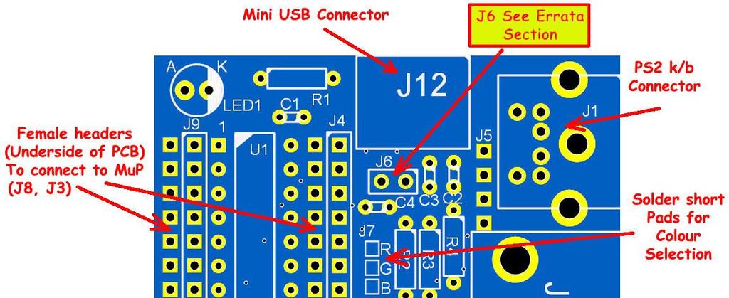
2 Board Concept. MuP-VT is a small 49.5mm x 49.5mm PCB that is based on Geoff Graham s ASCII Video Terminal (AVT), which is a VT100 based terminal PCB based on a PIC32MX250F128B microprocessor. The AVT can communicate via a USB cable to a PC and appears to the PC as a serial port. Full hardware design for the ASCII Video Terminal project can be found here: MuP-VT is designed to plug into MuP and, indeed, will not function without out it as power is sourced from the 3v3 regulator that is catered for on MuP. MuP-VT connects to MuP via 3 female headers that are mounted on the underside of the PCB (J3, J5 & J8). 5v power is routed from the Mini USB connector, J12, transferred to MuP (via J5) and 3v3 is in turn is transferred back up J5 to MuP-VT. Important NOTE! I had MuP-VT almost fully tracked when I decided as a last minute to add an isolation header (J6) to the 5V supply from the mini USB header so that, if desired, MuP-VT could be powered from an external power source whilst still connected to a PC. In theory it was a good idea but I mucked it up and inadvertently connected 5V to 3v3 if the header J6 was installed. Luckily the fix is fairly easy. Step 1. (I will do this before I ship out any boards) Using a drill fitted with a 4mm (3/16 ) drill bit, carefully drill out just the top pad from the right hand side of J6 as shown below:

3 Step 2. Solder a short link between the bottom pad of C2 and the top pad of R4, this is best done on the bottom layer of the PCB and probably easiest if the top leg of R4 is trimmed leaving a short 3mm length that can be bent over and soldered to C2. The pads to be connected are shown in this picture of the underside of the board. There is no need to install J6 as it will, in effect, do nothing. The reason I have drilled away the pad is, if at a later date, someone installs the J6 link no damage will be done to either Mup-VT or MuP. If at a later date I do another run of MuP-VT I will, of course, reinstate J6 with a corrected track layout. Construction MuP-VT looks easy to build and apart from the sole surface mount component (J12) is not too difficult to do. However there are a few `gotchas that can ruin your day if MuP-VT is not assembled in the correct order. The following is my suggested order for assembling MuP-VT with minimal fuss. J7 (top of the PCB) These are `solder short pads for selecting the colour that the VGA monitor will display (Usually all 3 pad pairs will be solder shorted to select white text). J10 (bottom of the board) These are `solder short pads for selecting the baud-rate of the communication with the PC via the USB connection. (Usually these are left OPEN for software control.
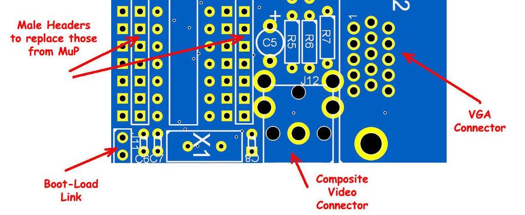
4 My recommendation is to not link any of the pads of J10 as the baud-rate can be software selected from the configuration menu (Shift F12), MuP-VT will remember this setting for the next time it is powered up. Configuration settings are shown in the table below: Table reprinted. With kind permission Of Geoff Graham. J12 (mini USB connector) As the only surface mount component it is best to fit this part next. I would have liked to use a through hole part here but whilst through hole mini USB connectors are actually available they are not easy to find and are not particularly cheap. Resistors, Capacitors, Led and X-Tal Should be installed next, remember to leave a short length of the `top leg of R4 to bend over to solder onto the bottom leg of C2 (see text in Step 2 above). Headers J3, J4, J5, J8, J9 & J11, U1 Should be installed now, but be careful as due to the closeness of these headers/ic socket if they are not soldered in the order I recommend you will find it difficult to do without risking damage to the headers. The suggested order is as follows: J4 (Male, Top of the board) J3 (Female, Bottom of the board) U1 (IC 28pin IC socket) J9 (Male, Top of the board) J8 (Female, Bottom of the board) J11 (Male, Top of the board) J5 (Female, Bottom of the board)


5 J1, J2 & J13 (RCA Socket incorrectly labelled as J12 on overlay) Finally the larger connectors can be fitted. Take care that any metalwork/casing of the connectors do not touch any of the other components. Whilst the connectors I used are typical of most of the ones out there, there are some variations between manufacturers. You are now ready to fit MuP-VT to MuP. I find this is easiest by aligning the female header, J5, with the MuP s male header, J3, and then pressing the two boards together, making sure that the other two female headers, J3 & J8 mate correctly with MuP male headers, J3 & J4. Bill of Materials NOTE! There are many different sizes and pin-outs styles for the VGA and RCA sockets, the items mentioned above will work, chose styles that are the same as those Element14/Farnell parts listed above.

6 Schematic NOTE! Due to tracking error J6 is redundant in Ver. 1 (Consider J6 Closed permanently) *** See text ***
.")
7 ADDENDUM J6 and 5V Power source As mentioned earlier, the original intention of J6 was to allow MuP-VT (and MuP) to be powered from the USB socket (with J6 installed). OR Powered, via MuP, from an external 5v source (with J6 not installed). Unfortunately, due to my stuff up, the `fix' means that the J6 link option will be `not there' so the only way to power MuP-VT (and MuP as well) is through the USB port. (either via a PC connection or a 5v USB `Wall-Wart plug pack) It is possible to power through an external supply, connected to MuP, ONLY if the USB is NOT also plugged in, or a track cut to remove power in on pin 1 of the USB connector. (Right hand side pin of J12 as the overlay is shown). A picture of where to cut is shown below, however I really do not recommend this option. If I do a Ver. 2 MuP-VT, I will fix the functionality of J6. J11 (Bootload) The J11 jumper is the `bootload link which has the same functionality as the `bootload link on Geoff s original Ascii Video Terminal. See: For full details of the `bootload link and the Ascii Video Terminal project.
UF-3701 Power Board Construction Guide
 Page 1/5 Soldering and Part Placement See the Chapter 3 of the MIT 6270 Manual for information on electronic assembly, including soldering techniques and component mounting. Construction Information All
Assembly Guide. LEDs. With these assembly instructions, you can easily build your own SWT16. All required components are included in this kit.
 Assembly Guide With these assembly instructions, you can easily build your own SWT16. All required components are included in this kit. You need the following tools: soldering iron, wire cutter and solder.
Post Tenebras Lab. Written By: Post Tenebras Lab
 Post Tenebras Lab PTL-ino is an Arduino comptaible board, made entirely out of through-hole components. It is a perfect project to learn how to solder and start getting into the world of micro controllers.
TIME WIZARD MULTI CLOCK DIVIDER BUILDING GUIDE
 TIME WIZARD MULTI CLOCK DIVIDER BUILDING GUIDE Table of Contents 0. Components List + Tools 0. PCB Sides 03. PCB Assembly 04_. Diode N448 04_. Laying Resistors 04_3. Capacitors 04_4. Quartz 04_5. 78L05
BuffaloLabs WiFi Lantern Assembly guide version 1
 BuffaloLabs WiFi Lantern Assembly guide version 1 Needed equipment: Solder iron Solder wire Cutter Wire stripper (optional) Hot glue gun Overview of the components (not including USB cable and box panels)
RC Tractor Guy Controller V2.1 Assembly Guide
 RC Tractor Guy Controller V. Assembly Guide Features 0 Push button inputs Dual axis thumb sticks with built-in push button Rotary encoders with built-in push button MCU Socket to suit Meduino Mega 560
Schematic Diagram: R2,R3,R4,R7 are ¼ Watt; R5,R6 are 220 Ohm ½ Watt (or two 470 Ohm ¼ Watt in parallel)
") Nano DDS VFO Rev_2 Assembly Manual Farrukh Zia, K2ZIA, 2016_0130 Featured in ARRL QST March 2016 Issue Nano DDS VFO is a modification of the original VFO design in Arduino Projects for Amateur Radio by
Nano DDS VFO Rev_2 Assembly Manual Farrukh Zia, K2ZIA, 2016_0130 Featured in ARRL QST March 2016 Issue Nano DDS VFO is a modification of the original VFO design in Arduino Projects for Amateur Radio by
Quicksilver 606 TR-606 CPU Upgrade
 Quicksilver 606 TR-606 CPU Upgrade D650C 128 Installation Guide Social Entropy Electronic Music Instruments TABLE OF CONTENTS WARNINGS... 1 OVERVIEW... 2 WHAT'S IN THE BOX... 3 OPENING THE TR-606 CASE...
SharpSky Focuser Construction. SharpSky Focuser. Construction Document V st December 2012 Dave Trewren 1
 SharpSky Focuser Construction Document V0.12 1st December 2012 Dave Trewren 1 Contents 1 General... 3 1.1 Change Record... 3 1.2 References... 3 2 Introduction... 5 3 SharpSky driver installation... 5
CP5176 Assembly guide. Soldering. CP5176 Assembly guide Main PCB PCB split. Document revision 2.1 Last modification : 12/11/17
 CP5176 Assembly guide Safety warning The kits are main powered and use potentially lethal voltages. Under no circumstance should someone undertake the realisation of a kit unless he has full knowledge
Lab 0: Wire Wrapping Project: Counter Board
 Lab 0: Wire Wrapping Project: Counter Board September 3, 2008 In this experiment, you will build a simple counter circuit that can be plugged into your breadboard. It will provide a set of TTL output signals
Hauptwerk Hardware 2016
 Hauptwerk Hardware Interface Board for the Universal Midi Encoder User Manual Page 1 Release 1.2 February 2016 Table of Contents Introduction...3 Board Overview...4 IMPORTANT PLEASE READ...5 Mounting...6
Construction Construction Instructions
 Semi-Virtual Diskette SVD Construction Construction Instructions PCB version 2.0 September 2004 Eric J. Rothfus Table of Contents Table of Contents... i Parts List...1 Construction Overview...5 PCB Construction...
Touch Sense Controller
 Touch Sense Controller Paul Boston May 11, 2011 (Modified May 22, 2014) (Modified Dec 28, 2015) The Touch Sense Controller is a microprocessor-controlled circuit designed to provide a switch closure when
MAIN PCB (The small one)
") THANKS FOR CHOOSING ONE OF OUR KITS! This manual has been written taking into account the common issues that we often find people experience in our workshops. The order in which the components are placed
THANKS FOR CHOOSING ONE OF OUR KITS! This manual has been written taking into account the common issues that we often find people experience in our workshops. The order in which the components are placed
Installing PRO/DGX or Pro Soloist MIDI interface. R Grieb 9/08/2017
 Installing PRO/DGX or Pro Soloist MIDI interface. R Grieb 9/08/2017 Please read these instructions before purchasing the MIDI interface, to make sure you are comfortable performing the necessary steps.
EE 354 August 1, 2017 Assembly of the AT89C51CC03 board
 EE 354 August 1, 2017 Assembly of the AT89C51CC03 board The AT89C51CC03 board comes as a kit which you must put together. The kit has the following parts: No. ID Description 1 1.5" x 3.25" printed circuit
Phi-panel backpack assembly and keypad options Dr. John Liu 12/16/2012
 Phi-panel backpack assembly and keypad options Dr. John Liu 12/16/2012 1. Introduction:... 3 Currently available:... 3 2. Backpack assembly... 4 3. Connecting to a keypad... 6 4. Rotary encoder keypads...
Pi PoE Switch HAT Quick Start And FAQ. Getting started. Kit contents
 Pi PoE Switch HAT Quick Start And FAQ Getting started The Pi PoE Switch HAT is an add on board for the Raspberry Pi that brings the Switch technology together with PoE all in one fantastic package! You
Electronics Construction Manual
 Electronics Construction Manual MitchElectronics 2018 Version 1 07/05/2018 www.mitchelectronics.co.uk CONTENTS Introduction 3 How To Solder 4 Resistors 5 Capacitors 6 Diodes and LEDs 7 Switches 8 Transistors
The Sudden Storm Kit. by QRPme. Builder s Guide. version4.2. for. Sudden Storm ][ Ver4 (red pcb) Updated 01/10/2012
![The Sudden Storm Kit. by QRPme. Builder s Guide. version4.2. for. Sudden Storm ][ Ver4 (red pcb) Updated 01/10/2012](/thumbs/75/72448638.jpg "The Sudden Storm Kit. by QRPme. Builder s Guide. version4.2. for. Sudden Storm ][ Ver4 (red pcb) Updated 01/10/2012") The Sudden Storm Kit by QRPme Builder s Guide version4.2 for Sudden Storm ][ Ver4 (red pcb) Updated 01/10/2012 Open the can and the adventure begins 1 Organize the parts and take an inventory Bill of Materials
The Sudden Storm Kit by QRPme Builder s Guide version4.2 for Sudden Storm ][ Ver4 (red pcb) Updated 01/10/2012 Open the can and the adventure begins 1 Organize the parts and take an inventory Bill of Materials
Ca Bling! Pacificon 2011 Norcal Buildathon Project
 Ca Bling! Pacificon 2011 Norcal Buildathon Project 10/23/2011 ver 1.1 by W1REX / QRPme www.qrpme.com The Ca Bling! Kit is a small Picaxe micro controller development board designed by W1REX as a project
Building the VMW Time Circuitry Meter by Vincent M. Weaver 6 May 2014
 Building the VMW Time Circuitry Meter http://www.deater.net/weave/vmwprod/hardware/time_circuit/ by Vincent M. Weaver 6 May 2014 1 Introduction This is a work in progress. I will update it as I complete
MuP-Security. Ver Aug-14
 MuP-Security Ver. 1.0 18-Aug-14 bigmick58@bigpond.com Preamble: The MuP-Security project came about due to a request from David Hall, a member of `The Back Shed Forum, for a board that could plug into
3 pyro output datalogger altimeter with an ATmega 328 microcontroller Kit assembly instructions
 3 pyro output datalogger altimeter with an ATmega 328 microcontroller Kit assembly instructions Version date Author Comments 1.0 29/05/2013 Boris du Reau Initial version Rocket Type Micro-max Model Mid
W0EB/W2CTX DSP Audio Filter Construction Manual V3.02.1
 W0EB/W2CTX DSP Audio Filter Construction Manual V3.02.1 Manual and photographscopyright W0EB/W2CTX, January 01, 2019. This document may be freely copied and distributed so long as no changes are made and
Electronics Construction Manual
 Electronics Construction Manual MitchElectronics 2019 Version 3 04/02/2019 www.mitchelectronics.co.uk CONTENTS Introduction 3 How To Solder 4 Resistors 5 Capacitors 6 Diodes and LEDs 7 Switches 8 Transistors
MICRO-TRAK 300 MANUAL VER 1.4
 MICRO-TRAK 300 MANUAL VER 1.4 The Micro-Trak 300 Version 1.4 is a miniature APRS (Automatic Position Reporting System) transmitter operating on the North American APRS frequency standard of 144.390 MHz.
Insert the male, 90 angled, 2x10 connectors into the corresponding 2x10 sockets and put them in place, flat under the PCB. Solder.
 MC624 Assembly guide Safety warning The kits are main powered and use potentially lethal voltages. Under no circumstance should someone undertake the realisation of a kit unless he has full knowledge about
GLiPIC Ver C Assembly manual Ver 1.0
 GLiPIC Ver C Assembly manual Ver 1.0 Last Rev 1.1 Oct 30, 2001 Author: Ranjit Diol Disclaimer and Terms of Agreement As with any kit, only the individual parts supplied are guaranteed against defects and
PARTS LIST 1 x PC Board 36 x 5mm Red LED 36 x 12mm LED Standoff 36 x NPN Transistor 36 x 10kΩ Resistor OTHER PARTS YOU MAY NEED
 PARTS LIST 1 x PC Board 36 x 5mm Red LED 36 x 12mm LED Standoff 36 x NPN Transistor 36 x 150Ω Resistor 36 x 10kΩ Resistor 17 x Mini Toggle on-off 8 x Mini Toggle (on)-off-(on) 1 x 470Ω Resistor 1 x 47µF
High Power (15W + 15W) Stereo Amplifier
 Stereo Amplifier") High Power (15W + 15W) Stereo Amplifier Build Instructions Issue 1.0 Build Instructions Before you put any components in the board or pick up the soldering iron, just take a look at the Printed Circuit
High Power (15W + 15W) Stereo Amplifier Build Instructions Issue 1.0 Build Instructions Before you put any components in the board or pick up the soldering iron, just take a look at the Printed Circuit
Chill Interface PCB Assembly Instructions
 ExcelValley Chill Interface PCB Waveblaster Module MIDI Interface Board Chill Limited Edition V2 Assembly Kit Standalone midi interface board for Waveblaster synthesizer modules. Suitable for most Waveblaster
Sprinkler Controller Assembly Manual
 Sprinkler Controller Assembly Manual V1.0 Doug Jackson VK1ZDJ September 2010 Licence The Sprinkler Controller Design, PCB layout, Manual, and Firmware is Copyright 2010, by Douglas Jackson, VK1ZDJ. This
Installation/assembly manual for DCC/Power shield
 Installation/assembly manual for DCC/Power shield The DCC circuit consists of the following components: R1/R6 R2/R3 R4/R5 D1 C2 2 kω resistor ½ Watt (colour code Red/Black/Black/Brown/Brown) 10 kω resistor
Building the FlipChip Tester
 Building the FlipChip Tester 1. Assembly of the Core Board You will need a fine low-wattage soldering iron and a Voltmeter. Take your time to solder the components on the Core Board. Better to spend a
Three Band Compact Low Pass Filter Kit
 Three Band Compact Low Pass Filter Kit The Three Band Compact Low Pass Filter provides a simple way to build up three selectable low pass filters on a single PCB. Low pass filters have many applications
MAIN PCB (The small one with the square cut out from one side)
") THANKS FOR CHOOSING ONE OF OUR KITS! This manual has been written taking into account the common issues that we often find people experience in our workshops. The order in which the components are placed
THANKS FOR CHOOSING ONE OF OUR KITS! This manual has been written taking into account the common issues that we often find people experience in our workshops. The order in which the components are placed
TH E FI N EST I N G E E K E NTE RTAI N M E NT
 HACKING the C a b l e M o d e m W h at c a b l e c o m pa n i e s d o n t wa n t yo u t o k n o w DerEngel BUILDING A CONSOLE CABLE The device shown in Figure 17-1 is an RS-232 to TTL converter board,
Building and using JasperMIDI
 Building and using JasperMIDI Table of Contents Introduction... Bill Of Materials... 2 Building Choices... 3 Construction... 4 Installing in a Jasper enclosure... 5 Standalone use... 6 Using JasperMIDI...
RS-232 Adapter Board
 User Manual Blue Wolf, Inc. 9179 W. State Street Garden City, ID 83714 Revision History Version # Release Date Revision/Release Comments 1.0 3/14/2011 Initial draft for release. The information contained
DLP-RFID2-EDK2 SETUP PROCEDURE
 DLP-RFID2-EDK2 SETUP PROCEDURE This product is designed to make it easy to both test the DLP-RFID2 module without developing your own hardware and provide an easy-to-use platform for those wishing to program,
Button Code Kit. Assembly Instructions and User Guide. Single Button Code Entry System
 Button Code Kit Single Button Code Entry System Assembly Instructions and User Guide Rev 1.0 December 2009 www.alan-parekh.com Copyright 2009 Alan Electronic Projects Inc. 1. Introduction... 4 1.1 Concept
Cumbria Designs T-1. C-1 Controller. User Manual
 Cumbria Designs T-1 C-1 Controller User Manual CONTENTS 1 INTRODUCTION 2 2 CIRCUIT DESCRIPTION 2 3 ASSEMBLY 3 4 CONNECTIONS AND CONFIGURATION 4 5 TESTING 6 Appendix A C-1 Circuit Diagram and PCB Component
HUB-ee BMD-S Arduino Proto Shield V1.0
 HUB-ee BMD-S Arduino Proto Shield V1.0 User guide and assembly instructions Document Version 1.0 Introduction 2 Schematic 3 Quick user guide 4 Assembly 5 1) DIP Switches 5 2) Micro-MaTch Connector Headers
Storage Card Interface Kit
 Storage Card Interface Kit for MultiMediaCards(MMC) and Secure Digital Cards (SD) MMSD3K The MMSD3K is complete development kit interfaced to a SD or MMC card. This board ideal for projects that involve
Ultimate LPF kit: Relay-switched LPF kit
 Ultimate LPF kit: Relay-switched LPF kit PCB Revision 4 1. Introduction Thank you for purchasing the QRP Labs relay-switched low-pass filter (LPF) kit. This kit is designed to complement the Ultimate3
Raspberry-Pi Shield: Binary-Coded-Decimal Clock
 Raspberry-Pi Shield: Binary-Coded-Decimal Clock ASSEMBLY INSTRUCTIONS What is it? This kit builds a binary-coded-decimal clock, driven by a Raspberry-Pi (which should be mounted on the back). This is a
BASIC Stamp 1 Project Board (#27112) Development / Education Platform for the BASIC Stamp 1
 Development / Education Platform for the BASIC Stamp 1") 599 Menlo Drive, Suite 100 Rocklin, California 95765, USA Office: (916) 624-8333 Fax: (916) 624-8003 General: info@parallax.com Technical: support@parallax.com Web Site: www.parallax.com Educational: www.stampsinclass.com
599 Menlo Drive, Suite 100 Rocklin, California 95765, USA Office: (916) 624-8333 Fax: (916) 624-8003 General: info@parallax.com Technical: support@parallax.com Web Site: www.parallax.com Educational: www.stampsinclass.com
Keysight Technologies How to build a fixture for use with the Keysight Cover-Extend Technology. Application Note
 Keysight Technologies How to build a fixture for use with the Keysight Cover-Extend Technology Application Note Introduction Cover-Extend Technology (CET) is Keysight s latest limited access solution for
Installing a LIF port into the IC-703 transceiver
 Installing a LIF port into the IC-703 transceiver Introduction This document describes the procedure for installing a LIF (Low Intermediate Frequency [9 18kHz]) port into the FT-950 transceiver. This procedure
Building the RGBW LED Controller
 Building the RGBW LED Controller A guide for the assembly and operation of your RGBW LED Controller. ver 3.1 Getting Started Parts list - You should have received the following parts: (1) Circuit Board,
K8099 NIXIE CLOCK. * optional enclosure TKOK19 (black) - TKOK17 (white) ** optional plexiglass enlcosure B8099 ILLUSTRATED ASSEMBLY MANUAL
 - TKOK17 (white) ** optional plexiglass enlcosure B8099 ILLUSTRATED ASSEMBLY MANUAL") Total solder points: 230 + 74 Difficulty level: beginner 1 2 3 4 5 advanced NIXIE CLOCK K8099 ** * A unique combination of both vintage and modern electronics ILLUSTRATED ASSEMBLY MANUAL H8099IP-1 * optional
Total solder points: 230 + 74 Difficulty level: beginner 1 2 3 4 5 advanced NIXIE CLOCK K8099 ** * A unique combination of both vintage and modern electronics ILLUSTRATED ASSEMBLY MANUAL H8099IP-1 * optional
USB Stamp Adapter Board
 User Manual Engineering» Design» Product Blue Wolf, Inc. 9179 W. State Street Garden City, ID 83714 Revision History Version # Release Date Revision/Release Comments 1.0 3/7/2011 Initial draft for release.
BMC24. MIDI TO GATE CONVERTER DOCUMENTATION. This documentation is for use with the "Euro Style" bottom board.
 BMC24. MIDI TO GATE CONVERTER DOCUMENTATION. This documentation is for use with the "Euro Style" bottom board. A. USING THE MIDI TO GATE CONVERTER B. PARTS LIST C. BUILDING INSTRUCTIONS D. SCHEMATICS Revision.
Shack Clock kit. U3S Rev 2 PCB 1. Introduction
 Shack Clock kit U3S Rev 2 PCB 1. Introduction Thank you for purchasing the QRP Labs Shack Clock kit. This clock uses the Ultimate3S QRSS/WSPR kit hardware, but a different firmware version. It can be used
The Basic Counter. Hobby Electronics Soldering Kit. Instruction Guide
 The Basic Counter Hobby Electronics Soldering Kit Instruction Guide TM For the best outcome, follow each step in order. We recommend reading this guide entirely before you get started. Tools required:
Microsystems. SCI-6 Sound Card Interface Kit Version 1.09 January 2015
 UM Unified Microsystems SCI-6 Sound Card Interface Kit Version 1.09 January 2015 The SCI-6 interface was designed to be a low cost, high quality interface between your PC s sound card and radio transceiver.
Propeller Proto Board (#32212) Propeller Proto Board USB (#32812) Proto Board Accessory Kit (# )
 Propeller Proto Board USB (#32812) Proto Board Accessory Kit (# )") Web Site: www.parallax.com Forums: forums.parallax.com Sales: sales@parallax.com Technical: support@parallax.com Office: (916) 624-8333 Fax: (916) 624-8003 Sales: (888) 512-1024 Tech Support: (888) 997-8267
Web Site: www.parallax.com Forums: forums.parallax.com Sales: sales@parallax.com Technical: support@parallax.com Office: (916) 624-8333 Fax: (916) 624-8003 Sales: (888) 512-1024 Tech Support: (888) 997-8267
KNIGHT S GALLOP ALGO-RHYTHMIC GENERATOR BUILDING GUIDE
 KNIGHT S GLLOP LGO-RHYTHMIC GENERTOR UILDING GUIDE Table of Contents 01. Components List + Tools 02. PC Sides 03. Important Note 04. Top PC ssembly 04_1. Diode 1N4148 04_2. Laying Resistors 04_3. Zenner
Single ROM Prototyping Board Pro 6502 (SRPB-PRO-6502) Instructions Version 1.2
 Instructions Version 1.2") Single ROM Prototyping Board Pro 6502 (SRPB-PRO-6502) Instructions Version 1.2 Copyright 2016 Brian E. Brzezicki http://www.arcade-cabinets.com Figure 1 Image of SRPB-PRO-6502 v1.1 PCB board Disclaimer
Single ROM Prototyping Board Pro 6502 (SRPB-PRO-6502) Instructions Version 1.2 Copyright 2016 Brian E. Brzezicki http://www.arcade-cabinets.com Figure 1 Image of SRPB-PRO-6502 v1.1 PCB board Disclaimer
BATC Kit MTK2 for MiniTiouner
 BATC Kit MTK2 for MiniTiouner Serit FTS4335V NIM Converter Document Change Log 2017-02-22 v1.01 First release 2017-03-01 v1.04 Minor mods Serit FTS4335V, Converter and MiniTiouner (built by G4KLB) Serit
Rapid28iXL PIC Prototyping PCB User Manual
 Description Features This is a PCB designed to facilitate the rapid prototyping of a device based on a 28 pin Microchip PIC microcontroller. To allow users to focus on their application, we take care of
Roger P. Ries, W9FIU Ries Labs, Inc Raven Road Farina, IL Phone:
 Roger P. Ries, W9FIU Ries Labs, Inc. 2275 Raven Road Farina, IL 62838 Phone: 618.238.1400 email: rpr@rieslabs.com Usage of the Syntor Frequency Prom Adapter: 1.) This adapter is useful only for VHF and
Sandevices E681 RGB Pixel Controller Assembly Manual
 Sandevices E681 RGB Pixel Controller Assembly Manual Oct 22, 2011 Oct 30, 2011 Initial Release Added component illustrations, silkscreen images, and misc text changes Prior electronic assembly experience
ArdPicProg. Arduino PIC Programmer Construction Manual. Version 1.2 Release date 03/2015. Gregor Schlechtriem
 ArdPicProg Arduino PIC Programmer Construction Manual Version 1.2 Release date 03/2015 Gregor Schlechtriem webmaster@pikoder.de www.pikoder.de Table of Contents Helpful Hints 3 Contents of the Kit and
Universal Keying Adapter 3+
 Universal Keying Adapter 3+ The Universal Keying Adapter Version 3+ kit will allow you to key nearly any transmitter or transceiver with a straight key, electronic keyer, computer serial or parallel port
Rapid40iXL PIC Prototyping PCB User Manual
 Description This is a PCB designed to facilitate the rapid prototyping of a device based on a 40 pin Microchip PIC microcontroller. To allow users to focus on their application, we take care of key housekeeping
*on-board power supply capability limited. External battery should be used for higher power servos.
 Pan and Tilt Decoder II PART NO. Add affordable Pan and Tilt control to your security cameras using the Pan and Tilt Decoder II and the DFRobot DF05BB Tilt/Pan Kit (5kg), Jameco PN 2144518 or the DAGU
Desktop housing AZ/EL Kit V1.2 for ERC-M Instructions. Instructions
 Instructions Desktop housing AZ/EL it V1.2 for ERC-M Instructions Congratulations for buying your Desktop housing AZ/EL for ERC-M. This document will guide you through the needed steps for assembly of
Deep Vibes. Wobbly Optical Vibe action
 Deep Vibes Wobbly Optical Vibe action Contents of this document are 2018 Pedal Parts Ltd. No reproduction permitted without the express written permission of Pedal Parts Ltd. All rights reserved. Important
SM010, Assembly Manual PCB Version 1.0
 180 SM010, Assembly Manual MATRIXARCHATE 16 8 IO SEQUENTIAL MATRIX SIGNAL ROUTER SM010 1 2 1 2 3 4 5 3 4 5 6 7 8 9 10 11 12 6 7 8 9 10 11 12 13 14 15 16 PROGRAM A B C D E F G H f1 f2 20.000 180 SSSR Labs
Shack Clock kit PCB Revision: QCU Rev 1 or QCU Rev 3
 1. Introduction Shack Clock kit PCB Revision: QCU Rev 1 or QCU Rev 3 Thank you for purchasing this QRP Labs Shack Clock kit. The kit uses the same PCB and bag of components as some other QRP Labs kits.
Onwards and Upwards, Your near space guide Overview of the NearSys Two Sensor Temperature Array Figure 1. A complete Two Sensor Temperature Array
 The NearSys Two Sensor Temperature Array is a kit that permits a BalloonSat to measure two separate temperatures. When plugged into a flight computer like the BalloonSat Mini, the flight computer provides
Custom O2+ODAC Soldering Instructions
 Custom O2+ODAC Soldering Instructions Preparations The following components should be omitted during basic assembly: R1, R2 D2, D6 BT2 The following components should be omitted based on required customization:
Pandora Assembly Instructions With Diamond Systems PC/104 CPUs (Athena, Elektra and Prometheus) November, 2006
 November, 2006") Pandora Assembly Instructions With Diamond Systems PC/104 CPUs (Athena, Elektra and Prometheus) November, 2006 Diamond Systems Corp. (650) 810-2500 www.diamondsystems.com This document describes how to
Pandora Assembly Instructions With Diamond Systems PC/104 CPUs (Athena, Elektra and Prometheus) November, 2006 Diamond Systems Corp. (650) 810-2500 www.diamondsystems.com This document describes how to
Figure 1. A complete Temperature Sensor
 The NearSys Temperature Sensor is a kit that permits a BalloonSat to measure the temperature of the air, interior, or object the sensor itself is placed in contact with. When plugged into a flight computer
[Note: Power adapter is not included in the kits. Users need to prepare a 9 12 V ( >300mA capacity ) DC power supply]
![[Note: Power adapter is not included in the kits. Users need to prepare a 9 12 V ( >300mA capacity ) DC power supply]](/thumbs/76/74094055.jpg "[Note: Power adapter is not included in the kits. Users need to prepare a 9 12 V ( >300mA capacity ) DC power supply]") 062 LCD Oscilloscope Assembly Notes Applicable Models: 06203KP, 06204KP DN062-18v02 Important Notes 1. Some components shown in the schematic and PCB layout are for options or adjustments. They do not
062 LCD Oscilloscope Assembly Notes Applicable Models: 06203KP, 06204KP DN062-18v02 Important Notes 1. Some components shown in the schematic and PCB layout are for options or adjustments. They do not
TLC5947 and TLC59711 PWM LED Driver Breakouts
 TLC5947 and TLC59711 PWM LED Driver Breakouts Created by Bill Earl Last updated on 2016-03-01 07:38:00 PM EST Guide Contents Guide Contents Overview Assembly Assembly: Soldering the Headers Position the
Thank you for purchasing the RGB Multi-MCU base and driver board from SuperTech-IT and TheLEDCube.com
 CONGRATULATIONS Thank you for purchasing the RGB Multi-MCU base and driver board from SuperTech-IT and TheLEDCube.com In this document, MCU means Microcontroller such as the PIC32, ATmega328P, prototype
Dwarf Boards. DB057 : 40-pin controller board
 Dwarf Boards DB057 : 40-pin controller board PICmicro, In-Circuit Serial Programming and ICSP are registered trademarks of Microchip Technology Inc. DB057 for USB PIC DB057 for non-usb PIC Introduction
Breadboard Voltage. Convenient 5V Supply for Breadboard
 Breadboard Voltage Regulator v2.1 Convenient 5V Supply for Breadboard Turn your 6~18VDC Wall Wart adapter into a regulated 5VDC @ 0.5 Ampere supply for your breadboard experiments! Build Time: 20mins Skill
A TCP/IP network CAT 5 cable If the network is faster than 10baseT a switching hub will be needed Static IP address
 Requirements A TCP/IP network CAT 5 cable If the network is faster than 10baseT a switching hub will be needed Static IP address Power Up A Reader with an Ethernet adaptor installed and the network cable
Rapid40i PIC Prototyping PCB User Manual
 Description This is a PCB designed to facilitate the rapid prototyping of a device based on a 40 pin Microchip PIC microcontroller. To allow users to focus on their application, we take care of key housekeeping
RHODEUS PANEL I/O BOARD
 RHODEUS PANEL I/O BOARD User Manual Revision A April 2011 Revision Date Comment A 4/11/11 Initial Release FOR TECHNICAL SUPPORT PLEASE CONTACT: Copyright 2011 Diamond Systems Corporation 555 Ellis Street
KK1L 2x6 Antenna Switch Relay Controller / Dual Band Decoder Basic Assembly Version 4.8 (new 24-Aug-2009) Parts List updated 19-AUG-2016
 Parts List updated 19-AUG-2016") KK1L 2x6 Antenna Switch Relay Controller / Dual Band Decoder Basic Assembly Version 4.8 (new 24-Aug-2009) Parts List updated 19-AUG-2016 Ronald Rossi, KK1L http://home.comcast.net/~kk1l Design Features:
KK1L 2x6 Antenna Switch Relay Controller / Dual Band Decoder Basic Assembly Version 4.8 (new 24-Aug-2009) Parts List updated 19-AUG-2016 Ronald Rossi, KK1L http://home.comcast.net/~kk1l Design Features:
MP3 audio amplifier. Build Instructions. Issue 2.0
 MP3 audio amplifier Build Instructions Issue 2.0 Build Instructions Before you put any components in the board or pick up the soldering iron, just take a look at the Printed Circuit Board (PCB). The components
PiRyte Mini ATX PSU Revision User Manual
 Revision 1.1.0 User Manual Overview Congratulations on your purchase of the PiRyte Mini ATX PSU! Please read this entire manual before using to ensure you receive maximum benefit from this board while
Super Skwisher. Ross Compressor +++
 Super Skwisher Ross Compressor +++ Contents of this document are 2015 Pedal Parts Ltd. No reproduction permitted without the express written permission of Pedal Parts Ltd. All rights reserved. Important
Reverse DDS Kit Construction
 Reverse DDS Kit Construction This kit is only recommended for home constructors experienced with Surface Mount construction so these notes are for guidance only. Mark out and drill the holes for the SMA
Modular Backplane for RC2014-Z80. Draft discussion document. Specification. Documentation by Stephen C Cousins Edition 0.4.0
 Modular Backplane for RC2014-Z80 Specification Draft discussion document Documentation by Stephen C Cousins Edition 0.4.0 CONTENTS Overview... 2 MODULE... 4 BUS...5 SECTION...6 Sections... 8 SECTION: STEPHEN
Arduino shield kit. 1) Low Pass Filter (LPF) kit (available for LF/MF/HF/VHF bands 2,200m to 6m)
 Low Pass Filter (LPF) kit (available for LF/MF/HF/VHF bands 2,200m to 6m)") Arduino shield kit 1. Introduction The QRP Labs Arduino shield kit is a versatile shield that can be used for various purposes. Write your own Arduino sketch to define the functionality! For example: 1)
Arduino shield kit 1. Introduction The QRP Labs Arduino shield kit is a versatile shield that can be used for various purposes. Write your own Arduino sketch to define the functionality! For example: 1)
Tone Bender Mk III. Grandaddy of super-cool vintage fuzz tone
 Tone Bender Mk III Grandaddy of super-cool vintage fuzz tone Contents of this document are 2014 Pedal Parts Ltd. No reproduction permitted without the express written permission of Pedal Parts Ltd. All
ATTiny84/85 AVR adapter kit building and usage instructions
 ATTiny84/85 AVR adapter kit building and usage instructions Version date Author Comments 1.0 25/06/2013 Boris du Reau Initial version 1.1 30/09/2013 Boris du Reau Updated document 1 Goal... 2 2 Kit content...
Manual Main PCB Small-MIDI 4
 Index PARTLIST MAIN PCB... 2 INTRODUCTION... 3 GENERAL... 3 THE CIRCUIT... 3 ASSEMBLY KIT... 4 ASSEMBLY OF THE PCB... 4 An important tip...... 4 ASSEMBLY... 4 THE CONNECTORS... 4 Power supply J1... 4 IDC
Images Scientific OWI Robotic Arm Interface Kit (PC serial) Article
 Article") Images Scientific OWI Robotic Arm Interface Kit (PC serial) Article Images Company Robotic Arm PC Interface allows real time computer control and an interactive script writer/player for programming and
Images Scientific OWI Robotic Arm Interface Kit (PC serial) Article Images Company Robotic Arm PC Interface allows real time computer control and an interactive script writer/player for programming and
RFX 328p dev/deployment board - Assembly instructions (long version, v1.3, Feb 12, 2015)
") RFX 328p dev/deployment board - Assembly instructions (long version, v1.3, Feb 12, 2015) Author: Mark Pendrith (support@embeddedcoolness.com) Kit overview The RFX 328/nRF24l01+/Proto dev board is a Arduino
RFX 328p dev/deployment board - Assembly instructions (long version, v1.3, Feb 12, 2015) Author: Mark Pendrith (support@embeddedcoolness.com) Kit overview The RFX 328/nRF24l01+/Proto dev board is a Arduino
Breakout Card For Z50Bus User Guide
 Breakout Card For Z50Bus User Guide For card: SC117 version 1.0 Design and Documentation by Stephen C Cousins Edition 1.0.0 CONTENTS OVERVIEW...2 PRINTED CIRCUIT BOARD... 4 SCHEMATIC... 5 WHAT YOU NEED...6
AT42QT101X Capacitive Touch Breakout Hookup Guide
 Page 1 of 10 AT42QT101X Capacitive Touch Breakout Hookup Guide Introduction If you need to add user input without using a button, then a capacitive touch interface might be the answer. The AT42QT1010 and
Storage Card Interface Kit
 Storage Card Interface Kit for MultiMediaCards(MMC) and Secure Digital Cards (SD) MMSD3F The MMSD3K is complete development kit interfaced to a SD or MMC card. This board ideal for projects that involve