Moving-Minds.com Treadmill Desk Operation
|
|
|
- Imogene Audrey Hodge
- 5 years ago
- Views:
Transcription


1 LifeSpan Treadmill Desk - Owner s Manual Models DT-5/DT-7 Desk Assembly DT-5 Desk Assembly Instructions Desk Leveling and Height Adjustment DT-7 Desk Assembly Instructions Desk Leveling and Height Adjustment DT-5 Manual Treadmill Desk Assembly DT-7 ElectricTreadmill Desk Assembly Treadmill Desk Operation Specifications Console Overview Innovative Features Troubleshooting Personal Settings
2 DT-5 Desk: Assembly Instructions At LifeSpan, we strive to make our equipment easy to assemble and start using. Parts that can be pre-assembled are always assembled and tested on the product line. Prior to starting the assembly process, take all the parts out of the box, remove plastic bags and lay everything out on the floor to become familiar with the components. Since your desk is a heavy piece of equipment, it is recommended that you use two people during assembly and follow these assembly instructions to avoid any problems that could occur. Item # Description 1 Lift Frame 2 Desktop 3 Left Base Foot 4 Right Base Foot 5 M8 Washer (Pre-installed) 6 M10 Acorn Nut (Pre-installed) 7 Height Adjustment Knob 8 LifeSpan Placard (Pre-installed) 9 M8*45L Bolt (Pre-installed) 10 M8 Nuts (Pre-installed) 11 Wire Cover 12 M10 Washer (Pre-installed) A Desk Position Bumpers B Extension Tube C Desktop Mounting Bracket D Stop Bumper E Bike Safety Key F Treadmill Safety Key Step 1: Lift Frame Assembly A. Position the lift frame (1), left base foot (3) and right base foot (4) as shown in the figure to the right. Note the position of the Workplace s logo, as well as the right and left base feet. B. Place the lift frame onto the left and right base feet mounting bolts, and install the M10 washer (5) and M10 acorn nut (6). C. Tighten the four mounting nuts. Step 2: Install the Height-Adjustment Knobs A. Locate the height-adjustment knobs (7). B. Screw the height-adjustment knobs into the lift frame (1) uprights, as shown in the figure to the right. C. Raise each extension tube (B) to level 15 and tighten the height adjustment knobs (7). 4
3 Step 3: Desktop Assembly A. Make sure the extension tube (B) is at level 15 (done in step 2C). B. Align the desktop on top of the extension tubes (B), so the wire harness from the desktop frame is on the same side as the wire harness coming from the right extension tube. Gently lower the desktop support frame onto the desktop mounting bracket (C). NOTE: Make sure the console wire harness or connector does not get caught or pinched between the mounting bracket and desktop frame. C. Insert four M8*45L carriage bolts (9) through the mounting brackets. Install four M8 washers (5) and nuts (10). Securely tighten the four M8 nuts. D. Connect the two wire harness connectors. NOTE: If the desktop tilts up and down slightly, re-tighten the four bolts/nuts inserted in step 3C. Step 4: Attach the Wire Cover to the Right Extension Tube Simply snap the cover (11) over the right extension tube (B). The bottom of the cover will be resting on top of the stop bumper (D). Safety Key When using the DT-5 with a treadmill, use safety key (F). Desk Leveling The desk needs to be leveled prior to use. The desk comes with two adjustable feet that can be used to level the desk and eliminate rocking. If the desk is rocking on two of the feet, adjust the two front feet until all four feet are sitting securely on the floor. 5
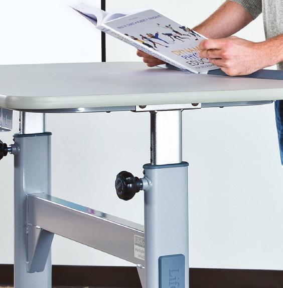
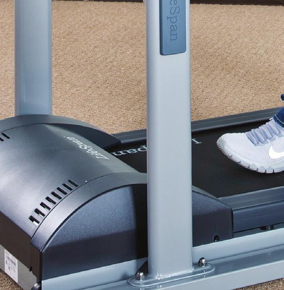
4 Desk Height Adjustment CAUTION: Remove all objects from the desktop prior to making height adjustments. We recommend using two people for the height adjustment. A. Loosen the adjustment knobs (A) on each upright by turning them no more than two turns counterclockwise. B. While firmly holding each side of the desktop, pull both adjustment knobs out and slowly raise or lower the desktop. C. Release the adjustment knob as the desired level is reached. The adjustment knob will click into place. D. Check to make sure the desk height is set at the same level on both sides. Turn the adjustment knobs clockwise to lock in place. Treadmill to DT-5 Desk Assembly A. Position the pre-assembled treadmill as shown below. B. Lift the rear of the treadmill and roll it forward under the desk until the positioning bumpers (D) located on the treadmill are centered over the treadmill position bumper (A) at the base of the uprights. C. Plug the console connector from the desk into the treadmill console port and tighten the thumb screws on the connector. D. Plug the power cord into the treadmill power receptacle and turn the power switch on. Be sure all connectors are plugged in prior to connecting the power cord. E. Install the safety key into the front of the console. 6
5 DT-7 Desk: Assembly Instructions At LifeSpan, we strive to make our equipment easy to assemble and start using. Parts that can be pre-assembled are always assembled and tested on the product line. Prior to starting the assembly process, take all the parts out of the box, remove plastic bags and lay everything out on the floor to become familiar with the components. Since your desk is a heavy piece of equipment, it is recommended that you use two people during assembly and follow these assembly instructions to avoid any problems that could occur. Item # Description 1 Lift Frame 2 Desktop 3 Left Base Foot 4 Right Base Foot 5 M8 Washer (Pre-installed) 6 M10 Acorn Nut (Pre-installed) 7 M8*45L Bolt (Pre-installed) 8 M8 Lock Nut (Pre-installed) 9 M8*15 Bolt (Pre-installed) 10 Accessory Tray 11 M10 Washer (Pre-installed) 12 LifeSpan Placard (Pre-installed) A Desk Position Bumper B Extension Tube C Desktop Mounting Bracket D Treadmill Safety Key E Bike Safety Key F Treadmill Safety Key Step 1: Lift Frame Assembly A. Position the lift frame (1), left base foot (3) and right base foot (4) as shown in the figure to the right. Note the position of the Workplace s logo, as well as the right and left base feet. B. Place the lift frame onto the left and right base feet mounting bolts and install the M10 washer (11) and M10 acorn nut (6). C. Tighten the four mounting nuts. 7
 with the holes in the crossbar. C. Install four M8 washers and M8*15 bolts (9) and tighten.")
, washers (5), and nuts (8), pre-installed in the upright assembly posts. B.")
6 Step 2: Accessory Tray Assembly A. Remove the four screws (9), pre-installed in the bottom of the upright assembly crossbar. B. Line the holes in the accessory tray (10) with the holes in the crossbar. C. Install four M8 washers and M8*15 bolts (9) and tighten. Step 3: Desktop Assembly NOTE: It is a good idea to use two people for this portion of the assembly, in order to ensure wires are properly routed and do not get pinched while installing the desktop. A. Remove the bolts (7), washers (5), and nuts (8), pre-installed in the upright assembly posts. B. Hold the desktop (2) over the lift frame (1), and place the desk height control wire harness (15) and the console wire harness (14) into the center of the lift frame (1). Place the connector ends toward the center of the tray for easy access in the next steps of the assembly. C. Set the desktop down into the mounting brackets (C) on the extension tubes, align the mounting holes and re-install the hardware removed in step A. D. Tighten the desktop mounting bolts/nuts. Step 4: Height Adjustment/Console Harness Connections A. Remove the two upper screws (13) attaching the access panel for the height-adjustment control unit. B. Tilt down and pull the access panel out several inches. There are harnesses pre-installed to the height controller, so do not try to fully remove. C. Attach the round connector (15) (placed in the center tray during desktop assembly) to the height controller port (16). D. Connect the 7-pin rectangular connectors (14) (one is placed in the center tray during desktop assembly and the other is pre-installed at the factory). E. Re-attach the access panel to the center tray and tighten the two screws removed in step A. F. Plug the power cord into the receptacle (19). NOTE: Check to be sure all wires are carefully tucked into the center tray prior to tightening access panel screws to prevent harness damage. 8

7 DT-7 Desk: Desk Leveling and Height Adjustment Desk Leveling The desk needs to be leveled prior to use. The desk comes with two adjustable feet that can be used to level the desk and eliminate rocking. If the desk is rocking on two of the feet, adjust the two front feet until all four feet are sitting securely on the floor. Desk Height Adjustment A. To raise the desk, press the Up or Down arrow until the desk is at the desired height. B. To save a height, press and hold the Memory Preset (1 or 2) button for three seconds. This will save the current height into memory. C. The next time the desk is used, simply press the Memory Preset to adjust the desk height to the previously saved setting. Safety Key When using the DT-7 with a Treadmill, use safety key (F). Treadmill to DT-7 Desk Assembly A. Position the pre-assembled treadmill as shown below. B. Lift the rear of the treadmill and roll it forward under the desk until the treadmill positioning bumper (D) located on the treadmill is centered over the desktop positioning bumper (A) at the base of the uprights. C. Plug the console electronics cable into the desk D-connector and treadmill console port and tighten the thumb screws. D. Plug the power cord into the desk power receptacle and into a wall outlet. E. Plug the power cord into the treadmill power receptacle and wall outlet. NOTE: Be sure all connectors are plugged in prior to connecting the power cord. F. Turn the treadmill power switch on and install the safety key into the front of the console. 9
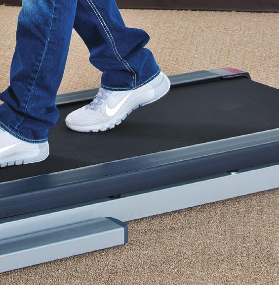
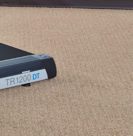
8 Treadmill Desk Operation Console DT-5 DT-7 Readouts Time, Steps, Calories, Distance, Speed Time, Steps, Calories, Distance, Speed Display LED LED Bluetooth Yes Yes Mechanics & Performance DT-5 DT-7 Speed Range mph kph mph kph Dimensions 46.75" W x 36.5" D cm W x cm D 46.75" W x 36.5" D cm W x cm D Height Adjustment 41" to 55" 104 cm to 140 cm 40" to 53" cm to cm User Height Range 4 10" to 6 8" 147 cm to 203 cm 4 10" to 6 8" 147 cm to 203 cm Height Adjustment Method Manual Electric Desktop Material 1" (2.54 cm) thick HD Composite Board 1" (2.54 cm) thick HD Composite Board Desktop Surface Durable Laminate Durable Laminate Maximum Load on Desktop 180 lbs, 82 kg 180 lbs, 82 kg Desk Lift Speed N/A 38 mm/second Desk Height Memory N/A 2 Presets Starting the Treadmill Desk 1. Turn the On/Off switch located on the front right corner of the treadmill to the On position. 2. Make sure the safety key is installed on the console. NOTE: The display will show "----" if the safety key is not installed. 3. The current user weight will be flashing on the display panel. Adjust your weight to obtain accurate calorie calculations. 4. Press the Start button to begin your workout. The console will start counting up from 00: Press the Up/Down buttons to adjust speed. NOTE: The steps are counted normally from 1 to 9,999 steps. After 9,999 steps, the display format changes to accommodate more than four digits. Take the number shown in the display and add a zero to the right for the correct number of steps. Below are examples of what the display will read and what those numbers mean: 1001 = 10,010 steps 1005 = 10,050 steps 1100 = 11,000 steps 10
.")
9 Treadmill Desk Console Overview Console Buttons 1. Start/On If the console is in sleep mode, press and hold this button for three seconds to turn the console on. Once the console is turned on, press to start the treadmill. 2. Enter/Mode Press to switch between display readings (time, steps, calories, distance, and speed). Holding the Enter/Mode button will initiate a scan mode that rotates between display readouts every five seconds. Press the button again to exit the scan mode. 3. Stop/Pause Press to pause your workout. This will maintain your current workout data. To reset the console and current workout data, press and hold the Stop/Pause button for three seconds. 4. Press to adjust your weight during setup mode or to change the treadmill speed during a workout. 5. Bluetooth Press to turn on Bluetooth to pair with a personal computer. NOTE: Not all personal computers have a Bluetooth module. A Bluetooth adapter can be purchased to work with your personal computer. Treadmill Desk Innovative Features Intelli-Guard This treadmill desk is equipped with our patented Intelli-Guard feature. This feature senses when you stop walking on the treadmill, and for safety purposes, it automatically pauses the treadmill to avoid accidental falls which may result in injury. The Intelli-Guard feature is triggered when the treadmill senses you are no longer walking. CAUTION: The Intelli-Guard feature will automatically be disengaged when the treadmill desk is operated at speeds under 1.0 mph (1.6 kph). If the speed is within these parameters, the step count will flash. When the display for the step count flashes, the treadmill desk will no longer auto-pause. CAUTION: At twenty seconds, the console will beep once per second for five seconds, and then automatically pause the treadmill desk. These beeps are a caution that the treadmill belt is about to stop. If for some reason you are still on the treadmill desk when this occurs, move your feet to the side rails and prepare for the belt to stop. The Intelli-Guard feature does not replace the use of your safety key or taking precautions to stop the treadmill desk when it is not in use. Intelli-Step This treadmill desk comes with our patented Intelli-Step counting feature. This feature senses the resistance on the walking belt each time your foot strikes. There are several factors that will affect the accuracy of this feature, including your walking style, your weight, and your usage characteristics. For example, the Intelli-Step feature will have a difficult time picking up the steps of a light user (under 110 lbs/50 kg) or at speeds lower than 1 mph (1.6 kph). Audible Safety Alert This treadmill desk has an audible alert to notify the user when the treadmill desk is starting as well as when the speed is being adjusted. The alert may be distracting in a school setting, and can be turned off. Please see the Personal Settings section for instructions on how to do so. 11
10 CAUTION: If the audible safety alert is turned off, the alert for the Intelli-Guard feature will also be disabled. Bluetooth The Workplace s series consoles include a Bluetooth module to support LifeSpan apps. All apps can be downloaded from the LifeSpan Fitness Club. Apps show real time results for steps, calories, distance, and time on your computer. Treadmill Desk Troubleshooting The LifeSpan Treadmill Desk is designed and manufactured to be reliable and easy to use. However, if you have a problem, these troubleshooting steps may help you find the cause. Only the weight LED is dimly lit. Pressing the start button will make the screen flash. The treadmill desk is in sleep mode. Press and hold the On/Start button for three seconds to power on the unit. The console is erratic or not lighting up. Check to make sure the treadmill desk is properly plugged in. Turn the power switch off and back on again and make sure the safety key is in place. Make sure the connectors located in the front of the treadmill and under the desktop are fully plugged in. If the problem persists, contact LifeSpan customer service. The treadmill motor seems strained or E1 comes up after several minutes of use. The silicone lubricant that is applied to the deck and belt is wearing down and the belt needs to be lubricated with 100% silicone spray (non-aerosol). The treadmill automatically pauses during a workout. The treadmill is not picking up the step count. Go into the Personal Settings section (page 32) to turn the IntelliGuard feature off. The treadmill speed doesn t feel right (either too fast or too slow). Go into the Personal Settings section (page 32) and check if you are in Metric or English mode. If you are in the correct mode, contact LifeSpan customer service. "Uart" appears in the display. Turn the treadmill desk power switch off. Unplug and re-plug the connections made in step 3C and 3D during assembly (DT-5), or step 4C and 4D (DT-7). Make sure the thumb screws are properly tightened. Turn the treadmill desk power back on and check to see if it functions properly. "dc-6" appears in the display. Turn the treadmill desk power switch off. Unplug and re-plug the connections made in step 3C and 3D during assembly (DT-5), or step 4C and 4D (DT-7). Make sure the thumb screws are properly tightened. Turn the treadmill desk power back on and check to see if it functions properly. 12
11 The console isn t connecting to personal computer via Bluetooth. Log into your LifeSpan Fitness Club account. Click on the Frequently Asked Questions link located at the bottom of the home page. If further assistance is needed, please coordinator@lifespanfitness.com. The treadmill desk does not go into sleep/energy-saving mode. In order for the unit to go into sleep/energy-saving mode, press and hold the stop button for three seconds to reset the console. After ten minutes, the console will go into sleep/energy saving mode. The desktop surface is not level. Check to make sure the base feet are on a level surface. For a DT-5, make sure each extension tube is raised to the same height number as shown on the extension tube. For a DT-7, run calibration by pressing and holding the height adjustment buttons simultaneously for three seconds. Treadmill Desk Personal Settings To enter Personal Settings mode, press and hold the Stop/Pause button simultaneously with the button. After three seconds, F001 should show in the display. 1. To change between English and Metric mode, press the button until F014 shows in the display. Press Enter, and either EN or SI will then appear in the display. To change to EN (miles) press the button. To change to SI (kilometers) press the button. Press enter and remove and re-install the safety key. 2. To turn the Intelli-Guard feature on or off, press the button until F012 shows up in the display. Press Enter so On/Off appears in the display. Press the button to turn Intelli-Guard off, or press the button to turn IntelliGuard on. Press Enter and remove and re-install the safety key. 3. To turn the Audible Alert on or off, press the button until F015 shows in the display. Press Enter so On/Off appears in the display. Press the button to turn the audible alert off, or press the button to turn the audible alert on. Press Enter and remove and re-install/ the safety key. WARNING The audible alert is turned on from the manufacturer to warn the user that the treadmill desk is starting or the speed is changing. Turning this alert off is done at the sole discretion of the user. 4. To change the allowable maximum speed from 4 mph (6.4 kph) to 2 mph (3.2 kph), press the button until F018 appears in the display. Press Enter, and 4.00 will show by default. Press the button, and 2.00 will be displayed. Press Enter and remove and re-install the safety key. 5. To start the treadmill at the speed it was going prior to pressing the Pause button, press the button until F019 appears in the display. Press Enter, and by default the display shows "0." Press the button to display a "1" and press Enter. Remove and re-install the safety key. 6. To find the running total distance you have walked, press the or button until F016 shows in the display. Press enter and the total distance will be displayed. 7. To find the total hours the treadmill desk has run, press the or button until F017 shows in the display. Press enter and the total hours will be displayed. 13
OWNERS MANUAL. Table of Contents. Treadmill/Bike Desks: DT-3/DT-5/DT-7. Getting Started 4 5. Welcome Warranty. Desk Assembly
 Table of Contents Getting Started 4 Welcome Warranty Desk Assembly OWNERS MANUAL Treadmill/Bike Desks: DT-3/DT-/DT-7 8 3 4 9 20 2 22 DT- Desk Assembly Instructions Desk Leveling and Height Adjustment DT-7
Treadmill Desk/Bike Desk Owner s Manual DT7
 Treadmill Desk/Bike Desk Owner s Manual DT7 Welcome Congratulations on choosing the LifeSpan Workplace line of products. These products give you the opportunity to remain productive while taking care of
200 lb (90.7 kg) 2 People Required. 250 lb (113.4 kg)
 2 People Required. 250 lb (113.4 kg)") Weight Capacity 200 lb (90.7 kg) 2 People Required Weight Capacity 250 lb (113.4 kg) 2 People Required x2 x4 x4 For patent and trademark information, visit VARIDESK.com/patents 2018 VARIDESK. All Rights
Weight Capacity 200 lb (90.7 kg) 2 People Required Weight Capacity 250 lb (113.4 kg) 2 People Required x2 x4 x4 For patent and trademark information, visit VARIDESK.com/patents 2018 VARIDESK. All Rights
Flex Pro Series Assembly Guide
 ELECTRIC HEIGHT-ADJUSTED SIT TO STAND DESK Table of Contents CAUTION, USE & LIABILITY... 2 PARTS & HARDWARE LIST... 3 PARTS / COMPONENT DIAGRAMS... 3 ASSEMBLY INSTRUCTIONS... 5 BLUETOOTH... 10 TROUBLESHOOTING...
Treadmill Integrated LCD Screen Option. Cardio Theater Integrated Bracket Assembly Instructions
 Treadmill Integrated LCD Screen Option Cardio Theater Integrated Bracket Assembly Instructions Table of Contents 1 2 3 4 5 6 Before You Begin... 4 Obtaining Service... 4 Unpacking the Equipment... 4 Important
Z-Truck (Vertical Moving) Z-truck Flag. Y-Truck (Horizontal Moving) FIGURE 1: VIEW OF THE Z-TRUCK. Flexshaft Assembly
 Z-truck Flag. Y-Truck (Horizontal Moving) FIGURE 1: VIEW OF THE Z-TRUCK. Flexshaft Assembly") Replacing the LCD Cable To remove and replace the LCD Cable you will need the following tools: #2 Phillips screwdriver (magnetic tip preferred) Socket wrench with 10mm socket Removing the Side Panel 1.
Replacing the LCD Cable To remove and replace the LCD Cable you will need the following tools: #2 Phillips screwdriver (magnetic tip preferred) Socket wrench with 10mm socket Removing the Side Panel 1.
UPLIFT 2-Leg Height Adjustable Standing Desk (Version v4 Control Box)
") UPLIFT 2-Leg Height Adjustable Standing Desk (Version v4 Control Box) DIRECTIONS FOR ASSEMBLY AND USE TABLE OF CONTENTS Also watch our assembly video http://bit.ly/2qvkeuf PAGE 1 Safety and Warnings 2
UPLIFT 2-Leg Height Adjustable Standing Desk (Version v4 Control Box) DIRECTIONS FOR ASSEMBLY AND USE TABLE OF CONTENTS Also watch our assembly video http://bit.ly/2qvkeuf PAGE 1 Safety and Warnings 2
SEQUEL 6051/6052 LIFT DESK
 SEQUEL 6051/6052 customerservice@ OWNER S MANUAL Product Registration Registering your new BDI product allows us to send you important product updates, service information and helpful hints related to
Ag Leader Technology Insight. Direct Command Installation Spra-Coupe 7000 Series
 Note: Indented items indicate parts included in an assembly listed above. Part Name / Description Part Number Quantity Direct Command Spra-Coupe 7000 Kit 4100531 1 Liquid Product Control Module 4000394
APES-14 HD-6500 & HD-7000 Version Operator s Training Manual
 APES-14 HD-6500 & HD-7000 Version Operator s Training Manual Issue A1 09/03 PDI Part # 900600 Performance Design Inc. 2350 East Braniff St. Boise Idaho 83716 This manual contains very important safety
Magnetic Upright Bike
 Magnetic Upright Bike Owner s Operating Manual Model: B890P - 1 - Adapter Book Stand (L2)Water bottle (K9) SCREW M6X15mm (K10) M6 ASSEMBLY OF REAR STABILIZER First, remove the bolts (B3), washers (B4)
UPLIFT 4-Leg Height Adjustable Standing Desk (Version v4.1 Control Box)
") UPLIFT -Leg Height Adjustable Standing Desk (Version v. Control Box) DIRECTIONS FOR ASSEMBLY AND USE TABLE OF CONTENTS PAGE Safety and Warnings 2 2 Usage 2 3 Parts List 3 Assembly Instructions 5 Desk Placement
UPLIFT -Leg Height Adjustable Standing Desk (Version v. Control Box) DIRECTIONS FOR ASSEMBLY AND USE TABLE OF CONTENTS PAGE Safety and Warnings 2 2 Usage 2 3 Parts List 3 Assembly Instructions 5 Desk Placement
Removal and Installation 8
 Removal and Installation 8 8 Introduction 8-2 Service Calibration Guide to Removal and Installation 8-4 Window 8-8 Covers and Trims 8-12 Rear Tray 8-31 Rear Cover 8-32 Media Lever 8-33 Media Lever Position
A-MOD DESKTOP OWNER S MANUAL
 A-MOD DESKTOP OWNER S MANUAL GOJOTTO.COM 877-55-6886 IMPORTANT NOTICE: Please take a few minutes to read through this Owner s Manual before using the product to ensure that your A-MOD Desktop will be operated
System Storage EXP3000 Rack Installation Instructions
 System Storage EXP3000 Rack Installation Instructions Review the documentation that comes with your rack cabinet for safety and cabling information. When you install the IBM System Storage EXP3000 in a
KRONOS 6752 LIFT DESK
 KRONOS 6752 OWNER S MANUAL Product Registration Registering your new BDI product allows us to send you important product updates, service information and helpful hints related to your BDI products. Register
CENTRO 6451/6452 LIFT DESK
 CENTRO 6451/6452 OWNER S MANUAL Product Registration Registering your new BDI product allows us to send you important product updates, service information and helpful hints related to your BDI products.
PREFACE. Thank you for choosing Zen Space Desks. We hope your desk helps you find your zen when being used. Zen Space Desks Team
 INSTRUCTION MANUAL PREFACE We are thrilled that you have chosen Zen Space. Congratulations, you have selected one of the most advanced and sophisticated Power Adjustable Workstations available today. Our
UPLIFT 3-Leg Desk Instructions for. Solid Wood Desktops. (Version v4 Control Box) pictured: Solid-wood top with right hand return TABLE OF CONTENTS
 pictured: Solid-wood top with right hand return TABLE OF CONTENTS") UPLIFT 3-Leg Desk Instructions for Solid Wood Desktops (Version v4 Control Box) pictured: Solid-wood top with right hand return TABLE OF CONTENTS PAGE 1 Safety and Warnings 2 2 Usage 2 3 Parts List 3 4
UPLIFT 3-Leg Desk Instructions for Solid Wood Desktops (Version v4 Control Box) pictured: Solid-wood top with right hand return TABLE OF CONTENTS PAGE 1 Safety and Warnings 2 2 Usage 2 3 Parts List 3 4
Cycles Integrated LCD Screen Option. Cardio Theater Integrated Bracket Assembly Instructions
 Recumbent Upright Cycles Integrated LCD Screen Option Cardio Theater Integrated Bracket Assembly Instructions Table of Contents 1 2 3 4 5 6 7 Before You Begin... 4 Obtaining Service... 4 Unpacking the
Assembly Guide T9200, T9500, T9600, AND T9700 PLATFORM TREADMILLS
 Assembly Guide T9200, T9500, T9600, AND T9700 PLATFORM TREADMILLS Assembly Guide T9200, T9500, T9600, AND T9700 PLATFORM TREADMILLS To avoid possible damage to this Platform Treadmill, please follow these
Replacement Instructions
 imac G5 Inverter, 20-inch Replacement Instructions Follow the instructions in this document carefully. Failure to follow these instructions could damage your equipment and void its warranty. Note: Online
ASTRO UW-1C and RW-1C LABEL PRINTER UNWINDER & WINDER
 ASTRO UW-1C and RW-1C LABEL PRINTER UNWINDER & WINDER OPERATOR MANUAL ASTRO MACHINE CORP. 630 Lively Blvd. Elk Grove Village, IL 60007 Phone: (847) 364-6363 Fax: (847) 364-9898 www.astromachine.com SAFETY
Portable Staging User Guide
 Portable Staging User Guide Components: ExpressDeck was designed for quick and easy assembly: set up is a snap, even if you have no experience! So let s take a moment to meet the components of your new
Ion Memory Upgrade. Visit the AMI Entertainment Web site PM
 Ion Memory Upgrade Visit the AMI Entertainment Web site http://www.meritgames.com PM0672-04 COPYRIGHT 2011 AMI ENTERTAINMENT NETWORK, INC. Ion Memory Upgrade CONTENTS: QTY PART NUMBER DESCRIPTION 1 EC0146-06
OPERATING MANUAL. Gilson Rice Shaker SGA-5R & SGA-5RT
 OPERATING MANUAL Gilson Rice Shaker SGA-5R & SGA-5RT Rev: 05/08/2018 PHONE: 800-444-1508 P.O. Box 200, Lewis Center, Ohio 43035-0200 FAX: 800-255-5314 740-548-7298 E-mail: customerservice@gilsonco.com
The Nureva Span ideation system. Installation guide. Single panoramic system
 The Nureva Span ideation system Installation guide Single panoramic system Important SAFETY WARNINGS Prior to the installation of this product, the installation instructions should be completely read and
Assembly and Setup Manual
 M-11 Series Copyboard/C-11 Series Captureboard Assembly and Setup Manual This is the installation and assembly manual for the M-11 series/c-11 series. To the Customer Specialized techniques are required
Note: These installation instructions are only for the 4430/4440 Sprayer. For other SPX models please refer to P/N , &
 DirectCommand Installation Ag Leader Technology Note: These installation instructions are only for the 4430/4440 Sprayer. For other SPX models please refer to P/N 2005944, 2005945 & 2006383. Part Name/Description
USER S MANUAL CAUTION ACTIVATE YOUR WARRANTY CUSTOMER CARE. Model No. CMTL Serial No.
 www.proform.com Model No. CMTL59712.0 Serial No. Write the serial number in the space above for reference. USER S MANUAL ACTIVATE YOUR WARRANTY Serial Number Decal To register your product and activate
13 MMC for PC Option Modules
 Part Number M.1300.8684 MMC for PC Option Modules Manual V3.0 The information in this document is also available in the MMC for PC Hardware Manual. 13 MMC for PC Option Modules 13.1 General The MMC for
Cisco TelePresence VX Clinical Assistant TM
 Cisco TelePresence VX Clinical Assistant TM ACCESSORIES INSTALLATION GUIDE Drawer Module, PC Cabinet Module, PC Shelf, and Storage Pods...2 Laptop Shelf...3 Scope Hooks, WAP Mount, and Splash Cover...4
2017 Treadmill Desks. Inspiring Movement at Work LifeSpan Workplace Treadmill Desk Brochure
 2017 Treadmill Desks Inspiring Movement at Work 2017 LifeSpan Workplace Treadmill Desk Brochure Design Options For the Pace of Your Office Design the solution to fit your needs: DT3 DT7 First Select a
RAM Rail Mount Kit RAM 201U 5 Arm RAM 2461U Monitor Mount RAM 235U Base, Double U-Bolt
 Note: Indented items indicate parts included in an assembly listed above Part Name/Description Part Number Quantity DirectCommand Kit 4100800 1 Cable Installation Kit 2000901-1 1 Dielectric Grease 2002872
Part Name/Description Part Number Quantity
 Part Name/Description Part Number Quantity Direct Command Kit 4100883 1 Installation Instructions 2006336 1 Hardware Kit Large Module 2001354-1 2 Cable Installation Kit 2000901-1 1 Quick Reference Card
Quick Installation Guide
 Full Motion Single Monitor Arm, Pole Mount Quick Installation Guide Please Review the entire Quick Installation Guide prior to installation. If you have any questions regarding the compatibility of this
HD NO HOLES MOUNT RAM SSV
 HD NO HOLES MOUNT 2015-2019 RAM SSV 425-5107 Remove the two trim covers to access the front OEM bolts of the passenger seat. Remove the front bolts using a 15mm socket. Align the base to the holes, snug
INSTRUCTION MANUAL. Instruction Manual. Analog Multi-Tube Vortexer Digital Multi-Tube Vortexer
 INSTRUCTION MANUAL Instruction Manual Analog Multi-Tube Vortexer Digital Multi-Tube Vortexer Table of Contents Package Contents............ 1 Warranty............ 1 Installation............ 2 Maintenance
OV1001 Part No OV1001 HEIGHT ADJUSTABLE TABLE USER GUIDE
 OV1001 Part No. 23620 OV1001 HEIGHT ADJUSTABLE TABLE USER GUIDE PRODUCT OVERVIEW User Guide: OV1001 OV1001 HEIGHT ADJUSTABLE TABLE A healthier work environment starts with the option to sit or stand throughout
Assembly Instructions
 Assembly Instructions Flat Screen Garage End User & IT Computer Cable Management May 2013 nylon zip-tie #2 (for computer wires) rear-access beam door (open) Figure 1 nylon zip-tie #1 (for #1 motor control
C764i Integrated LCD Screen Option. Cardio Theater Integrated Bracket Assembly Instructions
 C764i Integrated LCD Screen Option Cardio Theater Integrated Bracket Assembly Instructions Table of Contents 1 2 3 4 5 6 7 Before You Begin... 3 Obtaining Service... 3 Unpacking the Equipment... 3 Important
RAM Rail Mount Kit RAM 201U 5 Arm RAM 2461U Monitor Mount RAM 235U Base, Double U-Bolt
 DirectCommand Installation Ag Leader Technology Note: Indented items indicate parts included in an assembly listed above Part Name/Description Part Number Quantity DirectCommand Kit 4100852 1 Cable Installation
OLOGY HEIGHT-ADJUSTABLE DESKS. Troubleshooting Guide
 Troubleshooting Guide Power Cable Cantilevers Control Box Low-Voltage Cable Controller Lifting Column Foot Understructure OLOGY HEIGHT-ADJUSTABLE DESKS HOW THEY WORK Each Lifting Column contains an individual
OLOGY HEIGHT-ADJUSTABLE DESKS AND BENCHES. Troubleshooting Guide
 Troubleshooting Guide Power Cable Cantilevers Control Box Active Touch Controller Lifting Column Foot Understructure OLOGY HEIGHT-ADJUSTABLE DESKS AND BENCHES HOW THEY WORK Each Lifting Column contains
DUAL-ARM MONITOR MOUNT For in. ( cm) desktop computer monitors
 desktop computer monitors") LeviTouch DM-502 DUAL-ARM MONITOR MOUNT For 15 27 in. (38.1 68.6 cm) desktop computer monitors User Manual Thank you for choosing Gabor. The Gabor Dual-Arm Desktop Mount can securely support two monitors
LeviTouch DM-502 DUAL-ARM MONITOR MOUNT For 15 27 in. (38.1 68.6 cm) desktop computer monitors User Manual Thank you for choosing Gabor. The Gabor Dual-Arm Desktop Mount can securely support two monitors
OV1016 Part No OV1016 HEIGHT ADJUSTABLE BENCHING SYSTEM USER GUIDE
 OV1016 Part No. 86042 OV1016 HEIGHT ADJUSTABLE BENCHING SYSTEM USER GUIDE PRODUCT OVERVIEW User Guide: OV1016 OV1016 HEIGHT ADJUSTABLE BENCHING SYSTEM Our best-selling value table base is now available
Removal and Installation8
 8 Screw Types 8-4 Top Cover Assembly 8-5 Left Hand Cover 8-6 Right Hand Cover 8-10 Front Panel Assembly 8-14 Left Rear Cover 8-15 Right Rear Cover 8-16 Extension Cover (60" Model only) 8-17 Media Lever
TABLE OF CONTENTS SECTION 1 TABLETOP CONFIGURATION SECTION 2 TABLETOP CONFIGURATION ACCESSORIES SECTION 3 SLIDE CONFIGURATION
 S6 USER S MANUAL TABLE OF CONTENTS SECTION 1 TABLETOP CONFIGURATION SECTION 2 TABLETOP CONFIGURATION ACCESSORIES SECTION 3 SLIDE CONFIGURATION SECTION 4 SLIDE CONFIGURATION ACCESSORIES SECTION 5 RACK MOUNT
Cone Beam Volumetric Tomography and Panoramic Dental Imaging System
 Installation Manual Installation Manual Installation Manual Installation Manual Installation Manual Cone Beam Volumetric Tomography and Panoramic Dental Imaging System Gendex CB-500 Installation Manual
Quick Installation Guide
 Full Motion Dual Monitor Arm, Pole Mount Quick Installation Guide Please Review the entire Quick Installation Guide prior to installation. If you have any questions regarding the compatibility of this
Section. Service & Maintenance. - Core & Hard Disk Drive (HDD) - Amplifier - Monitor - UPS - Dollar Bill Acceptor - Fan Filter G - 1
 - Amplifier - Monitor - UPS - Dollar Bill Acceptor - Fan Filter G - 1") Section G Service & Maintenance - Core & Hard Disk Drive (HDD) - Amplifier - Monitor - UPS - Dollar Bill Acceptor - Fan Filter G - 1 Core Removal Core & HDD 1. Open the door. 2. Perform shutdown procedure.
Section G Service & Maintenance - Core & Hard Disk Drive (HDD) - Amplifier - Monitor - UPS - Dollar Bill Acceptor - Fan Filter G - 1 Core Removal Core & HDD 1. Open the door. 2. Perform shutdown procedure.
DYNAVISION D2 TM INSTALLATION MANUAL
 DYNAVISION D2 TM INSTALLATION MANUAL Rev 12 Dynavision International 8800 Global Way, West Chester, Ohio 45069 USA EMAIL:info@dynavisiond2.com, WEBSITE: www.dynavisiond2.com, FAX: (905) 294-6327 Unpacking
MAGIXBOX TM. Quick Start Guide
 TM TM by TouchMagix MAGIXBOX TM Quick Start Guide What s in the box: Ankle Ceiling Plate Extendable Rod Connector Piece Middle Piece Universal Spider Super clamp with ball socket Safety Cable Projector
OV1000 Part No OV1000 HEIGHT ADJUSTABLE TABLE USER GUIDE
 OV1000 Part No. 23624 OV1000 HEIGHT ADJUSTABLE TABLE USER GUIDE PRODUCT OVERVIEW User Guide: OV1000 OV1000 HEIGHT ADJUSTABLE TABLE A healthier work environment starts with the option to sit or stand throughout
3.5AE & 7.5AE Service Manual
 3.5AE & 7.5AE Service Manual 1 2 3 Contents CHAPTER 1: SERIAL NUMBER LOCATION... 5 CHAPTER 2: CONSOLE INSTRUCTIONS 2.1 Console Overview... 6 2.2 Display Window Indication... 8 2.3 Getting Started & Program
LED Lighting Kit For Elara NanoEdge Fixed Frame. Installation Guide. Attention: Read this guide before assembling your screen.
 LED Lighting Kit For Elara NanoEdge Fixed Frame Installation Guide Attention: Read this guide before assembling your screen. INTRODUCTION GETTING STARTED WARNING - Sharp Edges This product may contain
Installation guide. Double panoramic system. Triple panoramic system
 The Nureva Span ideation system Installation guide Double panoramic system Triple panoramic system October 2016 1 Important SAFETY WARNINGS Prior to the installation of this product, the installation instructions
TDM To MiniMech conversion ProceDure
 TDM To MiniMech conversion ProceDure (Model 9100 ATM) TDN 07102-00079 Apr 1 2009 CorporATe HeAdquArTers: 522 E. Railroad Street Long Beach, MS 39560 PHONE: (228) 868-1317 FAX: (228) 868-0437 COPYRIGHT
When You Need More Than Staples. Toll Free: Fax: Electric VeloBinder Operating Instructions
 When You Need More Than Staples. Toll Free: 800-658-8788 Fax: 801-927-3037 info@abcoffice.com Electric VeloBinder Operating Instructions IMPORTANT SAFEGUARDS Warning: For your protection, do not connect
OLOGY HEIGHT-ADJUSTABLE DESKS. Troubleshooting Guide
 Troubleshooting Guide Power Cable Cantilevers Control Box Low-Voltage Cable Controller Lifting Column Foot Understructure OLOGY HEIGHT-ADJUSTABLE DESKS HOW THEY WORK Each Lifting Column contains an individual
Rack Installation Instructions
 Rack Installation Instructions For System Storage EXP2512 and EXP2524 Express Storage Enclosures Use the instructions in this document to install an IBM System Storage EXP2512 Express Storage Enclosure
CHAPTER 2: USING MANAGER PREFERENCE. 2.1 Using Manager Mode Using CSAFE Console (back side) Access Layout...
 Access Layout...") S3x_OM_090507.indd 1 S3x_OM_090507.indd 2 CHAPTER 1: IMPORTANT SAFETY INSTRUCTIONS PAGES 1.1 Read and Save These Instructions... 01 1.2 Setting up the Stepper... 01 1.3 Installation Requirements... 01
S3x_OM_090507.indd 1 S3x_OM_090507.indd 2 CHAPTER 1: IMPORTANT SAFETY INSTRUCTIONS PAGES 1.1 Read and Save These Instructions... 01 1.2 Setting up the Stepper... 01 1.3 Installation Requirements... 01
Eaton LCD Lift Flat Panel Display System. Installation Guide
 Eaton LCD Lift Flat Panel Display System Eaton LCD Lift Flat Panel Display System Installation Guide Copyright 2011 Eaton Corporation, Worcester, MA, USA. All rights reserved. Information in this document
IBM. Rack Installation Instructions
 IBM Rack Installation Instructions Review the documentation that comes with your rack cabinet for safety and cabling information. When installing your server in a rack cabinet, consider the following:
Assembly and Setup Manual
 M-12 Series Copyboard / C-12 Series Captureboard Assembly and Setup Manual This is the installation and assembly manual for the M-12 series Copyboard and C-12 series Captureboard. (The copyboard and/or
DIGITAL OBSERVATION GUARD LOW PROFILE PAN TILT KIT USER MANUAL
 DIGITAL OBSERVATION GUARD LOW PROFILE PAN TILT KIT USER MANUAL Version 2.1 June 4, 2013 0 Table of Contents Low Profile Pan Tilt Kit Description... 3 Low Profile Pan Tilt Unit Basic Operation... 4 Mounting
Rack Installation Instructions
 Rack Installation Instructions Review the documentation that comes with your rack cabinet for safety and cabling information. When installing your server in a rack cabinet, consider the following: v Two
DIGITAL Server Rackmount Installation Guide
 DIGITAL Server Rackmount Installation Guide Part Number: ER-PCSRA-IA. E01 Digital Equipment Corporation December 1997 The information in this document is subject to change without notice and should not
Installation and Assembly: 2 x 2 Video Wall Ceiling Mount for 40" - 55" flat Panel Displays
 Installation and Assembly: 2 x 2 Video Wall Ceiling Mount for 40" - 55" flat Panel Displays Model: DS-VWT955-2X2 EXTENSION COLUMN (SOLD SEPARATELY) COMPATIBILITY Display width must be a minimum of 36"
ColorMaxLP Label Roll Rewinder
 ColorMaxLP Label Roll Rewinder 5/2017 INSTALLATION/OPERATOR MANUAL Included: Rewinder Base plate Power supply Power Cord Thumb screws Assembly instructions 1. Install base plate Lift front of printer and
ACCUFORCE PRO QUICK START GUIDE
 ACCUFORCE PRO QUICK START GUIDE Quick Start Guide 2.0 Copyright SimXperience 2018 Congratulations on the purchase of your SimXperience AccuForce Pro! Your AccuForce Steering System was designed to provide
DirectCommand Installation CASE IH SPX Ag Leader Technology. PN: Rev. E January 2014 Page 1 of 19
 Note: These installation instructions only cover installation on SPX 4420 Sprayers only. For installation on SPX 3230/3330 Sprayers refer to Installation Instructions P/N 2005945. For SPX 4430 refer to
INSTALLATION INSTRUCTIONS
 INSTALLATION INSTRUCTIONS 19 20 21 01 07 22 23 13 10 12 08 17 18 11 02 14 15 04 03 16 WELCOME PARTS LIST Thank you for purchasing this HealthPoint Technology Cabinet from Humanscale! Before you begin installing
MX-8000 User Manual MX Rev
 MX-8000 Rev. 070202 Greeting Thank you for purchasing PAITEC USA products. This manual is prepared to provide guidelines on how to properly operate and maintain MX-8000. Copyright Any of the contents should
25 Sport Scope Instruction Manual
 25 Sport Scope Instruction Manual Dear Customer, We appreciate your business and value your support for our product. At Sport Scope, we strive to provide our customers with quality, easy to use, and affordable
KM-4800w. Installation Guide
 KM-4800w Installation Guide TABLE OF CONTENTS page 1 Installation Requirements 2 2 Unpacking 3 2. 1 Unpacking 3 2. 2 Confirmation of Accessories 5 3 Leveling the Machine 7 4 Setup of the Roll Deck 9 5
Elite T5000 Service Manual
 Elite T5000 Service Manual 1 TABLE OF CONTENTS CHAPTER 1: SERIAL NUMBER LOCATION...3 CHAPTER 2: PREVENTATIVE MAINTENANCE 2.1 Preventative Maintenance. 4 2.2 Tension and Centering the Running Belt....6
Xpander Rack Mount 16 5U Gen 3 with Redundant Power [Part # XPRMG3-1625URP] User Guide
![Xpander Rack Mount 16 5U Gen 3 with Redundant Power [Part # XPRMG3-1625URP] User Guide](/thumbs/87/95580647.jpg "Xpander Rack Mount 16 5U Gen 3 with Redundant Power [Part # XPRMG3-1625URP] User Guide") Xpander Rack Mount 16 5U Gen 3 with Redundant Power [Part # XPRMG3-1625URP] User Guide Xpander Rack Mount 16 5U Gen 3 with Redundant Power (RP) supplies is a rack mount PCI Express (PCIe) expansion enclosure
Xpander Rack Mount 16 5U Gen 3 with Redundant Power [Part # XPRMG3-1625URP] User Guide Xpander Rack Mount 16 5U Gen 3 with Redundant Power (RP) supplies is a rack mount PCI Express (PCIe) expansion enclosure
Vortex Series 2-leg Desk Assembly Guide
 ELECTRIC HEIGHT-ADJUSTED SIT TO STAND DESK Vortex Series 2-leg Desk Assembly Guide For desk with underframe Model No. AL4628-XX REV-1509A Table of Contents IMPORTANT SAFETY INSTRUCTIONS... 3 CAUTION, USE
GPIB-232CT-A IBCL EPROM Installation Guide
 NATIONAL INSTRUMENTS The Software is the Instrument Installation Guide GPIB-232CT-A IBCL EPROM Installation Guide This guide describes how to replace the factory-installed EPROM that comes with your GPIB-232CT-A.
Setup Information Panosaurus May 3, 2011
 Setup Information Panosaurus 2.0 www.gregwired.com May 3, 2011 Please take the time to read all of the setup information to ensure success and ease of use of this tripod head. Much of the setup is a one
V.I.A. - Monitor Shroud
 V.I.A. - Monitor Shroud NOTE: Installing slatwall above a monitor shroud requires modification of the upper horizontal rail. See V.I.A. Slatwall assembly direction 939502328 for installation process. V.I.A.
120Ra-1 Pentium III Processor Installation Insert
 120Ra-1 Pentium III Processor Installation Insert PN: 455-01614-000 Proprietary Notice and Liability Disclaimer The information disclosed in this document, including all designs and related materials,
Cab Box Kit Dome Plug Cab Box Cab Box Lid
 DirectCommand Installation Ag Leader Technology Note: Indented items indicate parts included in an assembly listed above Part Name/Description Part Number Quantity Direct Command Kit 4100578 1 Cable Installation
EPSON ActionLaser Read This First. eepa POLLUTION PREVENTER
 EPSON ActionLaser 1400 Read This First eepa POLLUTION PREVENTER This booklet is to help you set up your printer and begin printing quickly. It also gives you instructions for routine maintenance. If you
A-dec 570L Dental Light on a DCS System INSTALLATION GUIDE
 A-dec 570L Dental Light on a DCS System INSTALLATION GUIDE C ONTENTS Choose an Installation Guide...... Before You Begin.............. 3 Disconnect the Light Cable........ 3 Cut the Light Cable............
Owner s Manual Havis Universal Tablet Cradle
 Owner s Manual Havis Universal Tablet Cradle Related Products Havis offers a wide variety of accessory products for use with the UT-301 Universal Tablet Cradle. For more information or to order, please
Power Supply, 17-inch
 apple imac G5 Power Supply, 17-inch Replacement Instructions Follow the instructions in this sheet carefully. Failure to follow these instructions could damage your equipment and void its warranty. Note:
Part Name/Description Part Number Quantity
 Part Name/Description Part Number Quantity Direct Command 4200159 1 Cable Installation Kit 2000901-1 1 Hood 37-pin DSub 2001808-37 2 Dielectric Grease 2002872 1 Dust Plug 12 Pin Gray 2002899-12N 1 Feature
SERIES 7 TABLES PRE-DECEMBER Troubleshooting Guide. IMPORTANT NOTE: This guide applies to models shipped prior to December 2015 only.
 Troubleshooting Guide Control Box (PRE-DECEMBER 2015) Low-Voltage Cable Cable Manager Controller Lifting Column Stretcher Foot Power Cable SERIES 7 TABLES PRE-DECEMBER 2015 HOW THEY WORK Each Lifting Column
Back Tilt Sensor Repair Kit [ ]
![Back Tilt Sensor Repair Kit [ ]](/thumbs/80/81750013.jpg "Back Tilt Sensor Repair Kit [ ]") Back Tilt Sensor Repair Kit [002-1377-00] Components: Potted Tilt Sensor & Harness...1 Cable Ties...8 Step 1: Position chair. A) Press chair up control button to raise chair seat approximately 26-28 above
Back Tilt Sensor Repair Kit [002-1377-00] Components: Potted Tilt Sensor & Harness...1 Cable Ties...8 Step 1: Position chair. A) Press chair up control button to raise chair seat approximately 26-28 above
TRC-190 User s Manual
 User s Manual Edition 3.2, May 2017 www.moxa.com/product 2017 Moxa Inc. All rights reserved. User s Manual The software described in this manual is furnished under a license agreement and may be used only
Instruction Manual Standard Multi-Position Stirrers Advanced Multi-Position Stirrers
 Instruction Manual Standard Multi-Position Stirrers Advanced Multi-Position Stirrers Table of Contents Package Contents.............. 1 Warranty.............. 1 Installation.............. 2 Maintenance
Dual TV/Monitor Desk Mount Stand (Duplex Series) Model: DE9E2S-S
 Model: DE9E2S-S") Dual TV/Monitor Desk Mount Stand (Duplex Series) Model: DE9E2S-S Instruction Manual Images may different from actual product Disclaimer It is Dyconn s intention to have all the correct information represented
Dual TV/Monitor Desk Mount Stand (Duplex Series) Model: DE9E2S-S Instruction Manual Images may different from actual product Disclaimer It is Dyconn s intention to have all the correct information represented
ELECRAFT P3 HIGH-PERFORMANCE PANADAPTER P3SVGA OPTION INSTALLATION AND OPERATING INSTRUCTIONS. Rev B, March 20, 2012
 ELECRAFT P3 HIGH-PERFORMANCE PANADAPTER P3SVGA OPTION INSTALLATION AND OPERATING INSTRUCTIONS Rev B, March 20, 2012 Copyright 2012, Elecraft, Inc. All Rights Reserved Contents Introduction... 3 Customer
Vision Fitness TF20-TF40-T40 Frame with Classic / Elegant / Touch Console Service Manual
 Vision Fitness TF20-TF40-T40 Frame with Classic / Elegant / Touch Console Service Manual 1 TABLE OF CONTENTS CHAPTER 1: SERIAL NUMBER LOCATION 1.1 Serial Number Location - TF20 Frame.....3 1.2 Serial Number
SERIES 5 TABLES/BENCH
 Wire Manager Driveshaft Driveshaft Cover Stretcher Power Cable Low-Voltage Cable Power Supply Master Motor (can be on either side) Controller Controller Cable Lifting Column Foot SERIES 5 TABLES/BENCH
CHASSIS INSTALLATION GUIDE
 SUPER SC942S-600 SC942i-600/550 SC942 CHASSIS INSTALLATION GUIDE 1.0 SUPER SC942 Chassis User's Guide Table of Contents Chapter I: Unpacking and Check Lists... 1-3 Chapter 2: Installation Procedures...
Serial No. OWNER S MANUAL. Installation & Operation
 Serial No. OWNER S MANUAL Installation & Operation Table of Contents Safety & Warranty Warnings 01 Parts List 02 GhostBed Electronics Quick Reference Guide... 03 Installation Guide 04 GhostBed Remote Control
MONARCH 9416 XL QUICK REFERENCE
 MONARCH 9416 XL QUICK REFERENCE This Quick Reference contains ribbon loading, supply loading, and general care, maintenance, and troubleshooting procedures for the 9416 XL Thermal Direct and 9416 XL Thermal