4511 MODBUS RTU. Configuration Manual. Universal trip amplifier. No. 4131MCM100(1402)
|
|
|
- Dina Simpson
- 5 years ago
- Views:
Transcription


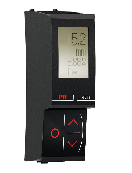
1 4511 MODBUS RTU Configuration Manual 4131 Universal trip amplifier 4131MCM100(1402) 4131
2 CONTENTS Introduction... 3 Modbus basics... 3 Modbus RTU... 3 Supported Function Codes... 3 Modbus Parameters and factory default settings... 3 Modbus RTU segment line termination Modbus Configuration Parameter List... 4 General Input Display... 4 Relay... 5 Display, ADV... 6 Input, ADV... 6 Relay, ADV... 6 Display units, table 1 and Input types and ranges Modbus Process Parameter List Modbus Configuration Parameter List Modbus Status Parameter List Modbus Front Programming Parameter List
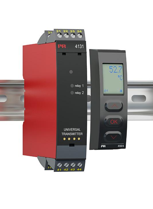
3 INTRODUCTION This configuration manual contains the necessary information for configuring a PR 4131 device which is connected to a PR 4511 Modbus RTU enabler. Modbus is a master-slave system, where the master communicates with one or multiple slaves. The master typically is a PLC (Programmable Logic Controller), DCS (Distributed Control System), HMI (Human Machine Interface), RTU (Remote Terminal Unit) or PC. The three most common Modbus versions used are: MODBUS ASCII, MODBUS RTU and MODBUS/TCP. In Modbus RTU, data is coded in binary, and requires only one communication byte per data byte. This is ideal for use over multi-drop RS485 networks, at speeds up to 115,200 bps. The most common speeds are 9,600 bps and 19,200 bps. Modbus RTU is the most widely used industrial protocol and is supported by the Modbus RTU: To communicate with a slave device, the master sends a message containing: Device - Function Code - Data - Error Check The Device is a number from 0 to 247. Messages sent to address 0 (broadcast messages) will be accepted by all slaves, but numbers are addresses of specific devices. With the exception of broadcast messages, a slave device always responds to a Modbus message so the master knows the message was received Supported Modbus Function Codes: Command Function code Read Holding s 03 Read Input s 04 Single 06 Diagnostics 08 Multiple s 16 The Function Code defines the command that the slave device is to execute, such as read data, accept data, report status. Some function codes have sub-function codes. The Data defines addresses in the device s memory map for read functions, contains data values to be written into the device s memory, or contains other information needed to carry out the function requested. The Error Check is a 16-bit numeric value representing the Cyclic Redundancy Check (CRC). Maximum number of registers which can be read or written at once: For a read command, the limit is 8 registers at a baud rate up to 38,400 bps, 16 57,800 bps and ,200 bps. For a write command, the limit is 123 registers at baud rates up to 115,200 bps Modbus parameter settings: Automatic Baudrate Detection: Can be configured YES or NO Supported baudrates: 2400, 4800, 9600, 19.2k, 38.4k, 57.6k, 115.2k bps Parity Mode: Even, Odd or None parity Stop Bits: 1 or 2 stop bits Response delay: ms (0 ms = default) Modbus slave addressing range: (247 = default address) Modbus Parameter Storage: Saved in non-volatile memory in the 4511 device (Factory Default Values are marked in bold) Modbus RTU segment line termination: A 120 Ohm resistor should be installed on both ends of a RS485 Modbus RTU segment loop to prevent signal echoes from corrupting data on the line. 3
4 4131 Modbus Configuration Parameter List Category Parameter DEVICE NUMBER DEVICE VERSION RO RO PASSWORD R/W TYPE R/W VOLTAGE RANGE CURRENT RANGE CONNECTION TYPE R/W R/W R/W LIN RES LOW R/W LIN RES HIGH R/W TEMP UNIT R/W TEMP SENSOR TYPE R/W PT TYPE R/W NI TYPE R/W TC TYPE R/W UNIT R/W DECIMAL POINT R/W Type LOW R/W HIGH R/W UNIT R/W Description Defines the actual device type Values Ver 0 Ver 1 Ver 2 Ver = (0x4131) Product version Password for entering configuration menu Selected input type (Voltage, Current, Resistance, Potentiometer, Temperature) Fixed input range for voltage measurements Fixed input range for current measurements Sensor connection type for RTD / resistance measurements Input range low for Linear resistance measurements Input range high for Linear resistance measurements. Temperature units Temperature sensor type Pt value (Pt10, Pt20, Pt50...) Ni value (Ni50, Ni100...) Thermocouple type (TCB, TCK...) Units shown as display units for non-temperature Decimal point place for display reading of non-temperature Low display range for display reading of non-temperature High display range for display reading of non-temperature Units for relay setpoint of non-temperature Pt10 = 0 Pt20 = 1 Pt50 = 2 Pt100 = 3 Pt200 = 4 Pt400 = 5 Pt500 = 6 Pt1000 = 7 table 1 Range: TEMP = 0 POTM = 1 LINR = 2 CURR = 3 VOLT = V = V = V = V = V = V = ma = ma = 1 2-wire = 0 3-wire = 1 4-wire = 2 Range: Range: C = 0 F = 1 TC = 0 Ni = 1 Pt = 2 TC = 0 Ni = 1 Pt = 2 Cu = 3 Pt10 = 0 Pt20 = 1 Pt50 = 2 Pt100 = 3 Pt200 = 4 Pt250 = 5 Pt300 = 6 Pt400 = 7 Pt500 = 8 Pt1000 = 9 Ni50 = 0 Ni100 = 1 Ni120 = 2 Ni1000 = 3 TC type B = 0 TC type E = 1 TC type J = 2 TC type K = 3 TC type L = 4 TC type N = 5 TC type R = 6 TC type S = 7 TC type T = 8 TC type U = 9 TC type W3 = 10 TC type W5 = 11 TC type Lr = 12 table 2 (except [blank]) XXXX = 0 X.XXX = 1 XX.XX = 2 XXX.X = 3 Range: Range: table 2 Percent = 0 Display units = 1 4
5 Category Parameter Type Description Values Ver 0 Ver 1 Ver 2 Ver 3 1 FUNCTION 1 CONTACT 1 SETPOINT 1 ACTION DIRECTION 1 HYSTERESIS R/W R/W R/W R/W R/W 1 ERROR ACTION R/W 1 ON DELAY 1 OFF DELAY 1 SETPOINT LOW WINDOW 1 SETPOINT HIGH WINDOW 2 FUNCTION 2 CONTACT 2 SETPOINT 2 ACTION DIRECTION 2 HYSTERESIS 2 ERROR ACTION 2 ON DELAY 2 OFF DELAY 2 SETPOINT LOW 2 SETPOINT HIGH CONTRAST BACKLIGHT R/W R/W R/W R/W R/W R/W Relay function (setpoint, window, error etc.) Contact function, (NO/NC or "open inside window"/"closed inside window") Setpoint in either display values or 1/10% (percent) for non-temperature and in 1/10 for temperature input types Activation direction Hysteresis in either display values or 1/10% (percent) for non-temperature, and in 1/10 for temperature input types Action on error Relay ON time delay Relay OFF time delay Low window setpoint in either display values or 1/10% (percent) for non-temperature, and in 1/10 for temperature input types High window setpoint in either display values or 1/10% (percent) for non-temperature, and in 1/10 for temperature input types OFF = 0 POWER = 1 ERROR = 2 WINDOW = 3 SETPOINT = 4 NC / Open inside window = 0 NO / Closed inside window = 1 Range for non-temperature : LOW... HIGH ( %) Range for temperature : equals the measurement range for the selected sensor type DECREASING = 0 INCREASING = 1 Range for non-temperature : 1...(display range/4) ( %) As 1 FUNCTION As 1 CONTACT R/W As 1 SETPOINT R/W R/W R/W R/W R/W Range for temperature : % (temperature sensor range/4) % NONE = 0 OPEN = 1 CLOSE = 2 HOLD = 3 Range: s Range: s As SETPOINT As SETPOINT As 1 ACTION DIRECTION As 1 HYSTERESIS As 1 ERROR ACTION As 1 ON DELAY As 1 OFF DELAY R/W As 1 SETPOINT LOW R/W As 1 SETPOINT HIGH R/W R/W TAG TEXT R/W ASCII CHAR LINE 3 FUNCTION R/W USE CALIB R/W PASSWORD FAST SET R/W R/W Contrast in the LCD display Backlight intensity in LCD Tag of the device (6 characters) Configured tag information shown in line 3 of display in monitor mode (normal mode). Use the applied calibration values Password protect entry to configuration menu Enable fast set of relay setpoints from monitor menu Range: 0..9 Range: 0..9 Range: ASCII values from 32 to 90 ( - to Z ). TAG = 1 5
6 Category Parameter Type Description Values Ver 0 Ver 1 Ver 2 Ver 3 CALIB RANGE LOW CALIB RANGE HIGH CALIB POINT LOW CALIB POINT HIGH HELPTEXT LANGUAGE R/W FLOAT R/W FLOAT R/W FLOAT R/W FLOAT R/W CJC TYPE R/W 1 LATCH 2 LATCH R/W R/W CU TYPE R/W SERIAL NUMBER RO CHECKSUM RO Configuration counter R0 Actual process value for low calibration point in either display values or 1/10 C Actual process value for high calibration point in either display values or 1/10 C Measured process value for low calibration point in either display values or 1/10 C (Must be copied from PROCESS DATA) Measured process value for high calibration point in either display values or 1/10 C (Must be copied from PROCESS DATA) Language for the help texts shown in display CJC compensation type for TC temperature types (internal/connector) Activate latch function Activate latch function Cu value (Cu10, Cu20, Cu50...) Device serial number CRC16 checksum of the configuration This counter will count the number of times the configuration has been changed. The counter is reset on power-up For non-temperature input: types range is LOW... HIGH For temperature : the range equals the measurement range for the selected sensor type None - Fixed internal None (Latch function not implemented) None (Latch function not implemented) As CALIB RANGE LOW As CALIB RANGE LOW As CALIB RANGE LOW UK = 0 DK = 1 DE = 2 FR = 3 SE = 4 IT = 5 ES = 6 None (Cu temperature type not implemented) None (Serial Number not part of CONFIGURATION DATA) Range Range INTERNAL = 0 CONNECTOR = 1 Cu10 = 0 Cu20 = 1 Cu50 = 2 Cu100 = 3 Range:
7 Table 1: Display units, ver 0 0 C 10 m 3 20 ft/min 30 MPa 40 GW 50 mv 60 gal/h 1 F 11 l 21 in/h 31 kpa 41 MW 51 W 61 t/h 2 K 12 s 22 ft/h 32 hpa 42 kw 52 S 62 mol 3 % 13 min 23 rpm 33 bar 43 hp 53 µs 63 ph 4 m 14 m/s 24 Hz 34 mbar 44 A 54 m 3 /min 5 cm 15 m/min 25 t 35 kj 45 ka 55 m 3 /h 6 mm 16 m/h 26 kg 36 Wh 46 ma 56 l/s 7 ft 17 in/s 27 g 37 MWh 47 µa 57 l/min 8 in 18 ft/s 28 N 38 kwh 48 V 58 l/h 9 yd 19 in/min 29 Pa 39 W 49 kv 59 gal/min Table 2: Display units, ver C 10 mils 20 in/s 30 t 40 kj 50 ka 60 m 3 /h 1 F 11 yd 21 ips 31 kg 41 Wh 51 ma 61 l/s 2 K 12 m 3 22 ft/s 32 g 42 MWh 52 µa 62 l/min 3 % 13 l 23 in/min 33 N 43 kwh 53 V 63 l/h 4 m 14 s 24 ft/min 34 Pa 44 W 54 kv 64 gal/min 5 cm 15 min 25 in/h 35 MPa 45 GW 55 mv 65 gal/h 6 mm 16 m/s 26 ft/h 36 kpa 46 MW 56 W 66 t/h 7 µm 17 mm/s 27 m/s 2 37 hpa 47 kw 57 S 67 mol 8 ft 18 m/min 28 rpm 38 bar 48 hp 58 µs 68 ph 9 in 19 m/h 29 Hz 39 mbar 49 A 59 m 3 /min 69 [blank]* [blank]* - not available in ver Input Types and Ranges Input type Min. value Max. value Standard ma V Pt10...Pt1000 Ni50...Ni1000 Cu10...Cu100 Lin. R Potentiometer TC B TC E TC J TC K TC L TC N TC R TC S TC T TC U TC W3 TC W5 TC LR 0 ma 0 V -60 C 0 Ω 10 Ω 0 C -100 C -100 C -180 C -180 C -50 C -50 C 0 C 0 C 20 ma 10 V +850 C +250 C +260 C Ω 100 kω C C C C +900 C C C C +400 C +600 C C C +800 C - - IEC DIN α = 0, DIN DIN ASTM E ASTM E GOST
8 Parameter 4131 Modbus Process Parameter List VALUE RO PERCENT PV RO MEASURE STATUS Type Description Values The measured value in 1/10 of C/ F for temperature Input types, or the scaled display value for non-temperature ( version of PRIMARY VALUE) The relative input value as 1/100 of % calculated from PRIMARY VALUE. For temperature % corresponds to the selected temperature range (OUTPUT LOW...OUTPUT HIGH) For non-temperature % corresponds to the selected fixed range (e.g ma) RO The actual measurement status ERROR STATUS RO The actual error status (Device errors) STATUS R/W PRIMARY RAW VALUE RO FLOAT PRIMARY VALUE R/W FLOAT RELATIVE PV RO FLOAT MEASURE CONTROL TIMEOUT COUNTER INTERNAL TEMPERATURE R/W R/W RO The actual relay status calculated from PRIMARY VALUE The measured value in 1/10 of C/ F for temperature Input types, or the scaled display value for non-temperature, NOT PROCESS CALIBRATED. The measured value in 1/10 of C/ F for temperature Input types, or the scaled display value for non-temperature. The relative input value calculated from PRIMARY VALUE. For temperature relative to selected temperature range (OUTPUT LOW...OUTPUT HIGH) For non-temperarure relative to selected fixed range (e.g ma) Measurement control. By disabling update of certain READ/WRITE parameters PRIMARY VALUE, OUTPUT VALUE or STATUS, these can be simulated by writing values. All bits are cleared when TIMEOUT COUNTER reaches 0 Time out counter, decrements every second. When reaching 0 (if not refreshed) all bits in MEASURE CONTROL will be cleared. Internal measured or connector temperature in 1/10 of C/ F Range for non-temperature : LOW... HIGH Range for temperature : equals the measurement range for the selected sensor type Range: (e.g = 78.98%) OUTPUT UNDERRANGE: bit 0 = 1 OUTPUT OVERRANGE: bit 1 = 1 OUTPUT LOW LIMITED: bit 2 = 1 OUTPUT HIGH LIMITED: bit 3 = 1 UNDERRANGE: bit 4 = 1 OVERRANGE: bit 5 = 1 SENSOR SHORTED: bit 6 = 1 SENSOR BROKEN: bit 7 = 1 AD COMM. ERROR bit 0 = 1 CJC ERROR bit 1 = 1 RAM ERROR bit 2 = 1 EEP ERROR bit 3 = 1 FLASH ERROR bit 4 = 1 NOT CALIBRATED bit 5 = 1 BAD OUTPUT bit 6 = 1 NO OUTPUT bit 7 = 1 OUTPUT SUPPLY ERROR bit 8 = 1 SUPPLY ERROR bit 9 = 1 EXT. FLASH ERROR bit 10 = 1 ALL VERSIONS: 1 INVERTED bit 0 = 1 2 INVERTED bit 1 = 1 1 IS ON bit 2 = 1 2 IS ON bit 3 = 1 1 WILL GO ON AFTER DELAY bit 4 = 1 2 WILL GO ON AFTER DELAY bit 5 = 1 ONLY VERSION 2-3: 1 IS LATCHED bit 6 = 1 2 IS LATCHED bit 7 = 1 1 CAN NOT RELEASE bit 8 = 1 2 CAN NOT RELEASE bit 9 = 1 Range for non-temperature : LOW... HIGH Range for temperature equals the measurement range for the selected sensor type Range for non-temperature : LOW... HIGH Range for temperature equals the measurement range for the selected sensor type Range: DISABLE PRIMARY VALUE UPDATE bit 2 = 1 DISABLE STATUS UPDATE bit 4 = 1 DISABLE CONFIGURATION CHECK bit 5 = 1 REMAINING BITS SHALL BE SET TO 0 Range: Range: ( C) or ( F) 8
9 Parameter MODBUS 4511 Modbus Configuration Parameter List R/W BAUDRATE R/W AUTOBAUD R/W Type Description Values Enable Modbus communication. If disabled, 4511 ignores all frames sent from the Modbus master and the only way to re-enable Modbus communication is by using the 4511 menu. The baud value used for Modbus communication Enable automatic baudrate detection. If enabled, 4511 determines the baudrate automatically by listening to frames sent on the Modbus line. PARITY R/W Configures parity check on Modbus frames STOPBITS R/W ADDRESS R/W RESPONSE DELAY R/W Configures the number of stopbits in Modbus frames Configures the Modbus address of the 4511 ( 0 is broadcast address) Configures minimum delay for Modbus response in ms 2400 BAUD = BAUD = BAUD = BAUD = BAUD = BAUD = BAUD = 6 NONE = 0 EVEN PARITY = 1 ODD PARITY = 2 ONE STOPBIT = 1 TWO STOPBITS = 2 Range: Range: Parameter AUTOBAUD STATUS IDENTIFY DEVICE MAXIMUM READ REGISTERS 4511 Modbus Status Parameter List Type Description Values RO Actual state of automatic baudrate detection R/W RO Enables the device to flash the LCD background with appr. 4 Hz. Value will automatically return to NO if not written within 10 seconds! Maximum allowed number of registers that can be read in one command, with the given/detected baudrate 2400 BAUD = BAUD = BAUD = BAUD = BAUD = BAUD = BAUD = 6 SEARCHING = 7 ERROR = 8 NO= 0 Range: "M" Scrolling HELP TEXTS: (correct) 4511 Modbus Front Programming Parameter Menu (NO) (YES) [1] Set correct password [2] Enter advanced setup menu [3] Perform memory operations Enter display setup Perform process calibration Enter simulation setup Enter password setup Enter language setup Enter rail setup (System 9000) Enter Modbus setup [4] Check automatic baudrate detection status Enable Modbus communication Disable Modbus communication [5] Reset Modbus to default [6] Select Modbus slave address [7] Select parity for Modbus [8] Select number of stop bits [9] Select response delay in ms [10] Enable automatic baudrate detection [11] Searching for Modbus baudrate Modbus baudrate detected Modbus baudrate not detected [12] Select baudrate in bps MODB MEM DISP CAL SIM PASS LANG RAIL (OFF) MODB (ON) *1) * 1) Only if automatic baudrate detection is enabled Please note: If no keys are activated for 1 minute, the 4511 display will return to the Monitor view without saving. The display will aslo return to "Monitor" upon successful Modbus write command! The grayed-out menus and texts are only shown for guidance and are not a part of the 4511 specific submenu. The Modbus submenu is located in the Advanced Setting menu structure of any host device using the The actual placement is defined for each particular device. MODB (YES) (NO) *1) "M" (YES) (NO) "M" 9
4511 MODBUS RTU. Configuration Manual. Universal trip amplifier. No. 4131MCM101(1445) For 4511 devices from ser. no:
 For 4511 devices from ser. no:") 4511 MODBUS RTU Configuration Manual 4131 Universal trip amplifier 4131MCM101(1445) For 4511 devices from ser. no: 141590001 4131 CONTENTS Introduction... 1 Modbus basics... 1 Modbus RTU... 1 4511 Supported
4511 MODBUS RTU Configuration Manual 4131 Universal trip amplifier 4131MCM101(1445) For 4511 devices from ser. no: 141590001 4131 CONTENTS Introduction... 1 Modbus basics... 1 Modbus RTU... 1 4511 Supported
4511 MODBUS RTU. Configuration Manual. Universal transmitter. No. 4114MCM100(1402)
") 4511 MODBUS RTU Configuration Manual 4114 Universal transmitter 4114MCM100(1402) 4114 CONTENTS Introduction... 3 Modbus basics... 3 Modbus RTU... 3 Supported Function Codes... 3 Modbus Parameters and factory
4511 MODBUS RTU Configuration Manual 4114 Universal transmitter 4114MCM100(1402) 4114 CONTENTS Introduction... 3 Modbus basics... 3 Modbus RTU... 3 Supported Function Codes... 3 Modbus Parameters and factory
4511 MODBUS RTU. Configuration Manual. Universal transmitter. No. 4116MCM101(1445) For 4511 devices from ser. no:
 For 4511 devices from ser. no:") 4511 MODBUS RTU Configuration Manual 4116 Universal transmitter 4116MCM101(1445) For 4511 devices from ser. no: 141590001 4116 CONTENTS Introduction... 1 Modbus basics... 1 Modbus RTU... 1 4511 Supported
4511 MODBUS RTU Configuration Manual 4116 Universal transmitter 4116MCM101(1445) For 4511 devices from ser. no: 141590001 4116 CONTENTS Introduction... 1 Modbus basics... 1 Modbus RTU... 1 4511 Supported
4511 MODBUS RTU. Configuration Manual. Universal transmitter. No. 4114MCM101(1445) For 4511 devices from ser. no:
 For 4511 devices from ser. no:") 4511 MODBUS RTU Configuration Manual 4114 Universal transmitter 4114MCM101(1445) For 4511 devices from ser. no: 141590001 4114 CONTENTS Introduction... 3 Modbus basics...3 Modbus RTU...3 4511 Supported
4511 MODBUS RTU Configuration Manual 4114 Universal transmitter 4114MCM101(1445) For 4511 devices from ser. no: 141590001 4114 CONTENTS Introduction... 3 Modbus basics...3 Modbus RTU...3 4511 Supported
4511 MODBUS RTU. Configuration Manual. Temperaure / ma converter. No. 9113MCM100(1338)
") 4511 MODBUS RTU Configuration Manual Temperaure / ma converter 9113MCM100(1338) 9113 CONTENTS Introduction... 3 Modbus basics... 3 Modbus RTU... 3 Supported Function Codes... 3 Modbus Parameters and factory
4511 MODBUS RTU Configuration Manual Temperaure / ma converter 9113MCM100(1338) 9113 CONTENTS Introduction... 3 Modbus basics... 3 Modbus RTU... 3 Supported Function Codes... 3 Modbus Parameters and factory
4511 MODBUS RTU. Configuration Manual. HART transparent driver. No. 9107MCM102(1739) For 4511 devices from ser. no:
 For 4511 devices from ser. no:") 4511 MODBUS RTU Configuration Manual HART transparent driver No. 9107MCM102(1739) For 4511 devices from ser. no: 141590001 9107 CONTENTS Introduction... 3 Modbus basics... 3 Modbus RTU... 3 4511 Supported
4511 MODBUS RTU Configuration Manual HART transparent driver No. 9107MCM102(1739) For 4511 devices from ser. no: 141590001 9107 CONTENTS Introduction... 3 Modbus basics... 3 Modbus RTU... 3 4511 Supported
Configuration Manual 4179 / 4511 Modbus RTU configuration of 4179 Universal AC/DC transmitter
 Configuration Manual 4179 / 4511 Modbus RTU configuration of 4179 Universal AC/DC transmitter PERFORMANCE MADE SMARTER TEMPERATURE I.S. INTERFACES COMMUNICATION INTERFACES MULTIFUNCTIONAL ISOLATION 4179MCM100-UK
Configuration Manual 4184 / 4511 Modbus RTU configuration of 4184 Universal uni-/bipolar signal transmitter
 PERFORMANCE MADE SMARTER Configuration Manual 4184 / 4511 Modbus RTU configuration of 4184 Universal uni-/bipolar signal transmitter TEMPERATURE I.S. INTERFACES COMMUNICATION INTERFACES MULTIFUNCTIONAL
4511 MODBUS RTU. Configuration Manual. Solenoid / alarm driver. No. 9203MCM100(1328)
") 4511 MODBUS RTU Configuration Manual Solenoid / alarm driver 9203MCM100(1328) 9203 CONTENTS Introduction... 3 Modbus basics... 3 Modbus RTU... 3 Supported Function Codes... 3 Modbus Parameters and factory
4511 MODBUS RTU Configuration Manual Solenoid / alarm driver 9203MCM100(1328) 9203 CONTENTS Introduction... 3 Modbus basics... 3 Modbus RTU... 3 Supported Function Codes... 3 Modbus Parameters and factory
4511 MODBUS RTU. Configuration Manual. Pulse isolator. No. 9202MCM101(1707) For 4511 devices from ser. no:
 For 4511 devices from ser. no:") 4511 MODBUS RTU Configuration Manual Pulse isolator No. 9202MCM101(1707) For 4511 devices from ser. no: 141590001 9202 CONTENTS Introduction...3 Modbus basics...3 Modbus RTU...3 4511 Supported Modbus Function
4511 MODBUS RTU Configuration Manual Pulse isolator No. 9202MCM101(1707) For 4511 devices from ser. no: 141590001 9202 CONTENTS Introduction...3 Modbus basics...3 Modbus RTU...3 4511 Supported Modbus Function
R1M-GH THERMOCOUPLE & DC INPUT MODULE MODEL. Remote I/O R1M Series. (16 points)
") Remote I/O R1M Series THERMOCOUPLE & DC INPUT MODULE (16 points) MODEL MODEL & SUFFIX CODE SELECTION R1MGH2T MODEL Modbus protocol I/O TYPE GH2 : Thermocouple or DC input, 16 points FIELD TERMINAL TYPE
Remote I/O R1M Series THERMOCOUPLE & DC INPUT MODULE (16 points) MODEL MODEL & SUFFIX CODE SELECTION R1MGH2T MODEL Modbus protocol I/O TYPE GH2 : Thermocouple or DC input, 16 points FIELD TERMINAL TYPE
I/O Module. Modbus Manual DMB Series.
 I/O Module Modbus Manual DMB Series www.drago-automation.de Before Startup When operating the signal converter, certain parts of the module can carry dangerous voltage! Ignoring the warnings can lead to
List of Contents 1. INTRODUCTION DEFINITIONS AND ABBREVIATIONS REFERENCES TECHNICAL DATA GENERAL MODBUS RTU...
 MAGX2 RTU User Guide -0- V1.5 23-01-2018 List of Contents 1. INTRODUCTION... 2 1.1 DEFINITIONS AND ABBREVIATIONS... 2 1.2 REFERENCES... 2 2. TECHNICAL DATA... 3 2.1 GENERAL MODBUS RTU... 4 3. COMMISSIONING...
Precision Digital Modbus Register Tables Serial Communication
 This document describes how to communicate with the Trident Model PD765 and Javelin D Model PD644 meters using the Modbus RTU Serial Communication Protocol. The user should be familiar with Modbus serial
Interface Definition RISH EM 2340/1320/30/ _Rev. D - 8/2016
 Interface Definition RISH EM 2340/1320/30/40 1 2-60-006-00-00494_Rev. D - 8/2016 2 Section DIGITAL MULTIFUNCTION INSTRUMENT Contents 1. Introduction Programmable Multi-function Energy Meter Installation
MODEL: 40DN. Digital Panel Meters 40 Series
 Digital Panel Meters 40 Series LOOP POWERED DIGITAL PANEL METER (4 digits, process meter) Functions & Features 4 digit (±9999) loop powered panel meter No external power source needed Scaling function
12-36 VDC/12-24 VAC Power Option 4-Digit Display, 0.56 (14.2 mm) or 1.20 (30.5 mm)
 or 1.20 (30.5 mm)") 4-20 ma & Relay Output Features 4-20 ma, ± 10 V, TC & RTD Inputs 12-36 VDC/12-24 VAC Power Option 4-Digit Display, 0.56 (14.2 mm) or 1.20 (30.5 mm) 24 VDC @ 200 ma Transmitter Power Supply Options Type
4-20 ma & Relay Output Features 4-20 ma, ± 10 V, TC & RTD Inputs 12-36 VDC/12-24 VAC Power Option 4-Digit Display, 0.56 (14.2 mm) or 1.20 (30.5 mm) 24 VDC @ 200 ma Transmitter Power Supply Options Type
CURRENT PROTECTION RELAY SMPR-1
 CURRENT PROTECTION RELAY SMPR-1 1.- ORION ITALIA SERIES MODBUS PROTOCOL. The ORION ITALIA SERIES implement a subset of the AEG Modicon Modbus serial communication standard. Many devices support this protocol
Trident and Trident X2 Digital Process and Temperature Panel Meter
 Sign In New User ISO 9001:2008 Certified Quality System Home Products Online Tools Videos Downloads About Us Store Contact Policies Trident and Trident X2 Digital Process and Temperature Panel Meter Products
Intech Micro 2300-RTD6 analogue input station MODBUS RTU slave application supplementary manual.
 Intech Micro 2300-RTD6 analogue input station MODBUS RTU slave application supplementary manual. MODBUS supplementary manual to the 2300-RTD6 Installation Guide. The 2300 series stations are designed to
D1000M SERIES FOR MODBUS SENSOR TO COMPUTER INTERFACE MODULES
 D1000M SERIES FOR MODBUS SENSOR TO COMPUTER INTERFACE MODULES D1000 FEATURES Complete sensor to RS-232/RS-485 interface. 500V rms analog input isolation. 15 bit measurement resolution. Continuous self-calibration;
MODEL: 43AL1. Digital Panel Meters 43 Series
 Digital Panel Meters 43 Series LOOP POWERED DIGITAL PANEL METER (process meter) Functions & Features Loop powered -1999 to 9999 compact digital meter Scaling function Screwless spring terminal 24 (.94)
Product manual 4179 Universal AC / DC transmitter
 Product manual 4179 Universal AC / DC transmitter PERFORMANCE MADE SMARTER TEMPERATURE I.S. INTERFACES COMMUNICATION INTERFACES MULTIFUNCTIONAL ISOLATION DISPLAY No. 4179V100-UK From serial no.: 171625001
HART Field Device Specification PR 5437 Device Revision 2
 HART Field Device Specification PR 5437 Version Revision: V4R0 Document Summary: This document explains the HART commands and features implemented in the PR 5437 transmitter, device revision 2. PR 5437
Masibus Automation And Instrumentation Pvt. Ltd.
 Operator s Manual DIGITAL CONTROLLER 5006H Masibus Automation And Instrumentation Pvt. Ltd. B/30, GIDC Electronics Estate, Sector-25, Gandhinagar-382044, Gujarat, India Ph: 91 79 23287275-79 Fax: 91 79
MODEL: 43DV2. Digital Panel Meters 43 Series
 Digital Panel Meters 43 Series DC INPUT DIGITA PANE METER (process meter) Functions & Features -1999 to +9999 digital panel meter Scaling & old functions available Screwless spring terminal (Input range:
Optidrive Applications Support Library
 Optidrive Applications Support Library Application Note Title AN-ODE-3-038 Related Products Optidrive E3 Overview Level 3 Modbus RTU Control and Register Mapping 1 Fundamental - No previous experience
MODEL: 47LYV. Digital Panel Meters 47 Series
 Digital Panel Meters 47 Series DC INPUT DIGITAL PANEL METER (4 1/2 digit, process meter, LED display type) Functions & Features 4 ½ digit DC input digital panel meter 1/8 DIN size Moving average function
C160 Wall-/Pipe Mounted Universal Process Indicator
 Data sheet DS/ EN Rev. I Wall-/Pipe Mounted Universal Process Indicator reliable process indicator, wherever it s needed High visibility LED display the clearest view of your process status 0.1% measurement
MODEL: 40DR SEN TRONIC AG. Digital Panel Meters 40 Series
 Digital Panel Meters 40 Series RTD INPUT DIGITA PANE METER (4 digits, process meter) Functions & Features 4 digit (±9999) panel meter functions igh visible, 0.8" (20.3mm) high and bright ED 48 (1.89) mm
MTL830 SERIES. Cuts installation and cable costs for all IS hazardous-area circuits
 830 SERIES Cuts installation and cable costs for all IS hazardous-area circuits Reduce the cost of installing hazardous-area cabling Save installation time, space and weight Highlight problems quickly
Intech Micro 2300-A8VI analogue input station MODBUS RTU slave application supplementary manual.
 Intech Micro 2300-A8VI analogue input station MODBUS RTU slave application supplementary manual. MODBUS supplementary manual to the 2300-A8VI Installation Guide. The 2300 series stations are designed to
Intrinsically Safe Temperature Concentrator System
 Intrinsically Safe Temperature Concentrator System Up to 32 Channels per Network HART and PC configurable 2, 3 & 4-wire RTD or Thermocouple Transmitter like Sensor Diagnostics and performance, RTD ±0.1
Product manual 4104 Universal uni-/bipolar signal transmitter
 Product manual 4104 Universal uni-/bipolar signal transmitter PERFORMANCE MADE SMARTER TEMPERATURE I.S. INTERFACES COMMUNICATION INTERFACES MULTIFUNCTIONAL ISOLATION DISPLAY No. 4104V101-UK From serial
TRACKER 220 SERIES. Digital Panel Indicators. A Complete Range of Universal Input Digital Panel Indicators for Temperature and Process Measurement
 TRACKER 220 SERIES Digital Panel Indicators A Complete Range of Universal Input Digital Panel Indicators for Temperature and Process Measurement TRACKER 220 SERIES INDICATORS Universal Input Analogue Output
The Tracker 220 Series A Complete Range of Universal Input Digital Panel Indicators for Temperature and Process Measurement
 Acquisition Measurement Control The Tracker 220 Series A Complete Range of Universal Input Digital Panel Indicators for Temperature and Process Measurement TRACKER 220 SERIES INDICATORS Universal Input
LAUREL. Laureate RTD Temperature Panel Meter / Controller ELECTRONICS, INC. Features. Description. Specifications
 LAUREL ELECTRONICS, INC. Laureate RTD Temperature Panel Meter / Controller Features Factory calibrated for 100Ω platinum, 10Ω copper & 120Ω nickel RTDs 2, 3 or 4-wire connection with lead resistance compensation
PD765 TRIDENT. Trident Series Process & Temperature Meters.
 PD765 Trident Series Process & Temperature Meters TRIDENT PROCESS & Temp 4-20 ma, ± 10 V, TC & RTD Inputs 4-Digit Display, 0.56 (14.2 mm) or 1.20 (30.5 mm) Type 4X, NEMA 4X, IP65 Front 1/8 DIN Shallow
IFC 100 Supplementary instructions
 IFC 100 Supplementary instructions Signal converter for electromagnetic flowmeters Description of Modbus interface Electronic Revision: ER 3.0.xx Modbus version: 1.0.xx KROHNE CONTENTS IFC 100 1 Important
Wall-/Pipe Mounted Universal Process Indicator
 Data Sheet SS/_8 Wall-/Pipe Mounted Universal Process Indicator High visibility LED display the clearest view of your process status 0.1% measurement accuracy precise indication of process measurement
RS-485 I/O Modules: ADAM-4000
 RS-485 I/O Modules: ADAM-4000 23 ADAM-4000 Series Overview ADAM-4000 Series Remote Data Acquisition and Control Modules Overview 23-2 and Controller Module Selection Guide 23-4 I/O Module Selection Guide
PD765 TRIDENT. Trident Series Process & Temperature Meters.
 PD765 Trident Series Process & Temperature Meters TRIDENT PROCESS & Temp 4-20 ma, ± 10 V, TC & RTD Inputs 4-Digit Display, 0.56" (14.2 mm) or 1.20" (30.5 mm) Linear or Square Root with Low-Flow Cutoff
High Voltage DC Meter
 High Voltage DC Meter Javelin D PD644 0-300 VDC input NEMA 4X, IP65 front Scale in engineering units Sunlight readable LED display 4-20 ma analog output Two form C 3 A relays option RS-485 serial communications
USER MANUAL. Modbus IHP24-A IHP24-AF IHP24-B IHP24-BF IHP24-F IHP24-I 1/26
 USER MANUAL Modbus IHP24-A IHP24-AF IHP24-B IHP24-BF IHP24-F IHP24-I 1/26 Table of contents 1 General... 3 1.1 Safety instructions... 3 2 Purpose... 4 3 Specifications... 5 3.1 Electrical specifications
ECHO Process Instrumentation, Inc. Modbus RS485 Module. Operating Instructions. Version 1.0 June 2010
 ECHO Process Instrumentation, Inc. Modbus RS485 Module Operating Instructions Version 1.0 June 2010 ECHO Process Instrumentation, Inc. PO Box 800 Shalimar, FL 32579 PH: 850-609-1300 FX: 850-651-4777 EM:
HIGH-VOLTAGE DC METER
 HIGH-VOLTAGE DC METER Javelin D PD644 0-300 VDC input NEMA 4X, IP65 front Scale in engineering units Sunlight readable LED display 4-20 ma analog output Two form C 3 A relays option RS-485 serial communications
Real Time Clock with Temperature Sensor and RS485/Modbus Comunications
 Real Time Clock with Temperature Sensor and RS485/Modbus Comunications April 29, 2014 Power 8 20 VDC @ less than 100 MA. Battery connect jumper RS485 Bus Load Jumpers Model: RTC-TI2C Page 1 of 6 Features:
KTA-250 Anemometer Alarm Card
 Connects to Davis Instruments DS7911 Anemometer Monitor both the wind speed and direction Interface to PLCs using the Modbus protocol Communicate via RS232 or 2-wire RS485 Interface to PLCs/Instruments
LAUREL ELECTRONICS, INC.
 LAUREL ELECTRONICS, INC. Laureate RTD Temperature Panel Meter / Controller Features Factory calibrated for 100Ω platinum, 10Ω copper & 120Ω nickel RTDs 2, 3 or 4-wire connection with lead resistance compensation
For Super-mini Signal Conditioners with Display M1E-UNIT USERS MANUAL
 For Super-mini Signal Conditioners with Display M1E-UNIT M1EA CONFIGURATOR SOFTWARE Model: M1EACFG USERS MANUAL 5-2-55, Minamitsumori, Nishinari-ku, Osaka 557-0063 JAPAN Tel: +81-6-6659-8201 Fax: +81-6-6659-8510
LD-RTD / LD-TC Temperature Controller
 1 LD-RTD / LD-TC Temperature Controller Available in either an RTD model or a thermocouple model, these units accept all common temperature probe types, and offer a technically advanced, but cost effective
SOFTWARE FUNCTIONAL REQUIREMENTS SPECIFICATION. Athena DeviceNet Interface Module Revision /26/2001
 SOFTWARE FUNCTIONAL REQUIREMENTS SPECIFICATION Athena DeviceNet Interface Module Revision 1.40 2/26/2001 Page 2 of 2 TABLE OF CONTENTS 1. RODUCTION...6 1.1 Overview...6 1.2 Document Scope...6 1.3 Definitions...6
smart meters... 6 panel meters... 7 field displays... 8 display types loop powered displays TRANSMITTERS & CONVERTERS...
 2 content DISPLAYS... 4 smart meters... 6 panel meters... 7 field displays... 8 display types... 10 loop powered displays... 12 TRANSMITTERS & CONVERTERS... transmitters... 15 converters... 18 serial data
Process & Temperature Digital Panel Meter
 Process & Temperature Digital Panel Meter TRIDENT PD765 4-20 ma, ± 10 V, TC & RTD Inputs NEMA 4X, IP65 Front Shallow Depth Case 3.6" Behind Panel Universal Power Supply 85-265 VAC Two Relays Option with
PowerLogic ION6200 Serial Communications Protocol and ION / Modbus Register Map
 70022-05-XX PROTOCOL DOCUMENT 04/2007 PowerLogic ION6200 Serial Communications Protocol and ION / Modbus Register Map This document explains the Modbus protocol on the ION6200 meter. The ION6200 meter
/8 DIN Universal Process Indicator
 Data Sheet SS/_ High visibility LED display the clearest view of your process status.% measurement accuracy precise indication of process measurement Analog and relay outputs as standard alarm and retransmission
SE-330 SERIES (NEW REVISION) MODBUS/TCP INTERFACE
 MODBUS/TCP INTERFACE") Tel: +1-800-832-3873 E-mail: techline@littelfuse.com www.littelfuse.com/se-330 SE-330 SERIES (NEW REVISION) MODBUS/TCP INTERFACE Revision 0-E-121117 Copyright 2018 Littelfuse Startco Ltd. All rights reserved.
Tel: +1-800-832-3873 E-mail: techline@littelfuse.com www.littelfuse.com/se-330 SE-330 SERIES (NEW REVISION) MODBUS/TCP INTERFACE Revision 0-E-121117 Copyright 2018 Littelfuse Startco Ltd. All rights reserved.
INTRINSICALLY SAFE DUPLEXER PROTECTION. ELECTRONICS, INC Vulcan Road Apopka, Florida MOTOR INSTRUCTION MANUAL
 INTRINSICALLY SAFE DUPLEXER INSTRUCTION MANUAL MOTOR PROTECTION ELECTRONICS, INC. 2464 Vulcan Road Apopka, Florida 32703 Phone: Website: (407) 299-3825 www.mpelectronics.com Operating Program Revision:
ProVU 4 Advanced Temperature & Process Controller
 ProVU 4 Advanced Temperature & Process Controller 1/4 DIN Format Graphical / text LCD Display (red/green) Profiling option Datalogging option (data, alarms & events) 5 language (English, French, German,
Copyright Extract from Conditions of Sale Safety Warning
 KD420 User Manual Copyright 2004-2013 KK Systems Ltd. No reproduction of any part of this document, in any form, is allowed without prior written permission from KKSystems Ltd. All other copyrights and
Intech Micro 2300-RO4 analogue input station MODBUS RTU slave application supplementary manual.
 Intech Micro 2300-RO4 analogue input station MODBUS RTU slave application supplementary manual. MODBUS supplementary manual to the 2300-RO4 Installation Guide. The 2300 series stations are designed to
1/32-DIN TEMPERATURE CONTROLLER INSTALLATION, WIRING AND OPERATION MANUAL FORM 3882
 1/32-DIN TEMPERATURE CONTROLLER INSTALLATION, WIRING AND OPERATION MANUAL FORM 3882 This manual is intended for use in support of installation, commissioning and configuration of the 1/32-DIN Temperature
1.Eastron SDM230Modbus Smart Meter Modbus Protocol Implementation V1.2
 1.Eastron SDM230Modbus Smart Meter Modbus Protocol Implementation V1.2 1.1 Modbus Protocol Overview This section provides basic information for interfacing the Eastron Smart meter to a Modbus Protocol
PRO-RTD Temperature Controller
 PRO-RTD Temperature Controller 1 This quad channel RTD controller is ideal for numerous industrial temperature applications. It accepts direct sensor input from RTD 385, 392 and CU10 temperature probes.
Optidrive VTC Modbus RTU Register Map
 Application Note AN-VTC- 39 Optidrive VTC Modbus RTU Register Map Author: Ning Xu, Invertek Drives Ltd Revision: 2.21 6 September 2006 General This document details the Modbus RTU memory mapping implemented
2 Table of Contents 1. TABLE OF CONTENTS. 1. Table of Contents Introduction Wiring Diagram Terminals Review...
 TPR-6 Temperature Protection Relay Instruction Manual Ver. June 1 st 2010 2 Table of Contents 1. TABLE OF CONTENTS 1. Table of Contents... 2 2. Introduction... 3 3. Wiring Diagram... 5 4. Terminals Review...
PLC PL User Manual
 PLC PL - 300 User Manual Contents list 1. Data acquisition module PL300... 3 1.1 Introduction... 3 1.2 Frontal panel... 5 1.3 Size and installation... 6 1.4 Electrical wirings... 7 1.4.1 Examples of sensors
INSTRUCTION MANUAL ESI-Manager communication How to use RS485 USB Ethernet connections
 INSTRUCTION MANUAL ESI-Manager communication How to use RS485 USB Ethernet connections Table of contents 1 Introduction to this manual... 4 1.1 Intended audience... 4 1.2 Before you start... 4 1.3 How
PD Helios Dual-Line 6-Digit Temperature Meter. Actual Size Digit
 PD2-7000 Helios Dual-Line 6-Digit Temperature Meter Actual Size Digit Temperature Large 1.80" Digits Dual-Line 6-Digit Display Readable from up to 100 Feet (30 Meters) Away Superluminous Sunlight Readable
SATEL I-LINK 100 MB I/O-converter User Guide, Version 1.1
 TABLE OF CONTENTS TABLE OF CONTENTS... 1 IMPORTANT NOTICE... 2 PRODUCT CONFORMITY... 3 WARRANTY AND SAFETY INSTRUCTIONS... 4 1 GENERAL... 5 1.1 SATEL I-LINK 100 MODBUS I/O- CONVERTER... 5 2 SPECIFICATIONS...
Operator Manual for Profibus
 PROCESS ANALYSERS SERVOPRO MultiExact Operator Manual for Profibus Part Number: Revision: Language: 05410007A 0 UK English This page intentionally blank LIST OF CONTENTS Section Page 1. DESCRIPTION AND
Modbus Protocol For FTS/FTM 3x&8x
 [ 公司地址 ] Modbus Protocol For FTS/FTM 3x&8x V3.0 Introduction This document describes the protocol detail of Modbus for FTSXX Hardware interface - The interface on the sensor is RS-485. - Hardware named
Chapter. Modbus. In This Chapter...
 Modbus Communication Chapter 7 In This Chapter... Modbus Protocol....7 2 Registers....7 2 Connection with the DirectLOGIC PLC....7 8 Connection with the C-more and C-more Micro HMI panels....7 10 Modbus
NetBiter I/O Extender User Manual
 User Manual Part no. 0920-9999-009 IntelliCom Innovation AB Pilefeltsgatan 73 SE-302 50 Halmstad SWEDEN Phone +46 35 17 29 90 Fax +46 35 17 29 09 email info@intellicom.se www www.intellicom.se Revision
INSTRUCTION MANUAL RVT communication How to use RS485 USB Ethernet RVT connections
 INSTRUCTION MANUAL RVT communication How to use RS85 USB Ethernet RVT connections Table of contents 1 Introduction to the controller... 1.1 Intended audience... 1.2 Before you start... 1.3 How to use this
Golander Peristaltic Pump MODBUS Communication Instruction
 Golander Peristaltic Pump MODBUS Communication Instruction 1 Introduction... 1 2 Modbus Protocol... 2 2.1 Modbus Protocol Model... 2 2.2 Byte Format... 2 2.3 MODBUS Message Timing... 2 2.4 Field... 3 2.5
PT2060 Monitor. PT2060/91 SIM System Interface Module. Specifications. Electrical. Messtechnik
 PT2060/ System Interface Module ProvibTech s PT2060/ module is a communication and system interface module. This module is used to: module. The two phase reference channels can be used to provide phase
TECHNICAL DATA SHEET. ProVU 4 Advanced Temperature Controller. Features. Description
 ProVU 4 Advanced Temperature Controller ¼ DIN Format Graphical / text LCD Display (red/green) Profiling option Datalogging option (data, alarms & events) 5 language (English, French, German, Italian, Spanish)
Version 1.0c May 6, 2010 ATK3
 Version 1.0c May 6, 2010 ATK3 Contents 1 Hardware 2 1.1 Inputs............................... 2 1.2 Outputs.............................. 3 1.3 RS485............................... 3 1.4 Ethernet..............................
MODEL: 40DV SEN TRONIC AG. Digital Panel Meters 40 Series
 Digital Panel Meters 40 Series DC INPUT DIGIT PNE METER (4 digits, process meter) Functions & Features 4 digit (±9999) panel meter Scaling and functions igh visible, 0.8" (20.3mm) high and bright ED 48
JDICON 1000 JDICON B Interface Description 3.99/ Universal Process Controller. Universal Profile Controller
 JDICON 1000 Universal Process Controller JDICON 1001 Universal Profile Controller B 70.3560.2 Interface Description 3.99/00316584 Contents 1 Introduction 1.1 Preliminary remarks... 3 1.2 Typographical
MPV. Process Panel Display. Dual-Line Rate and Total
 Process Panel Display Dual-Line Rate and Total measuring monitoring analyzing MPV Pulse or Analog s Displays Rate and Total Simultaneously Square Root Extraction 5, 10, or 24 V DC Flowmeter Power Supply
Temperature/Process Controllers Manual
 3200 SERIES Temperature/Process Controllers Manual The innovative range of 3200 controllers offer precision control of temperature and other process variables together with a host of advanced features
H3 Series. Nanmac Corporation. Dual-Line 6-Digit Temperature Meter.
 H3 Series Dual-Line 6-Digit Temperature Meter Temperature J, K, T, E, R, S, B, N, C Thermocouples 100 or 1000 Ω Platinum, 10 Ω Copper, 120 Ω Nickel RTDs 1 or 0.1 Resolution Averages up to 10 RTD Sensors
MODEL: SC100. Single Loop Controller Series. MULTI-FUNCTION PID CONTROLLER (color LCD with touch-panel) MODEL: SC100 [1]0 [2][3]
![MODEL: SC100. Single Loop Controller Series. MULTI-FUNCTION PID CONTROLLER (color LCD with touch-panel) MODEL: SC100 [1]0 [2][3]](/thumbs/79/79163563.jpg "MODEL: SC100. Single Loop Controller Series. MULTI-FUNCTION PID CONTROLLER (color LCD with touch-panel) MODEL: SC100 [1]0 [2][3]") Single Loop Controller Series MULTI-FUNCTION PID CONTROLLER (color LCD with touch-panel) 44 (5.67) 7 (.83) * mm (inch) *Selectable with option code /4: 400 mm /6: 600 mm Language blank: Japanese /E: English
Single Loop Controller Series MULTI-FUNCTION PID CONTROLLER (color LCD with touch-panel) 44 (5.67) 7 (.83) * mm (inch) *Selectable with option code /4: 400 mm /6: 600 mm Language blank: Japanese /E: English
GNM3D Series COMMUNICATION PROTOCOL. Version 1 Revision 0
 GNM3D Series COMMUNICATION PROTOCOL Version 1 Revision 0 Index 1.1 1.2 Introduction... 3 MODBUS functions... 3 1.2.1 Function 03h (Read Holding Registers)... 3 1.2.2 Function 04h (Read Input Registers)...
3690 N.W. 53rd Street Fort Lauderdale, FL SC-2124 SC-2124M. 24 Channel Universal Scanner. Installation and Operation Manual P/N 145F-11902
 3690 N.W. 53rd Street Fort Lauderdale, FL 33309 SC-2124 SC-2124M 24 Channel Universal Scanner Installation and Operation Manual P/N 145F-11902 Rev. 3.30 (c) Copyright 2000, Dynalco Controls All Rights
Type 70906X. Thyristor power units TYA 201, 202 and 203. Interface description for Types ,-62, and T92Z001K000. Typ /
 Type 70906X Thyristor power units TYA 201, 202 and 203 Typ 709061/8-01-020 Typ 709062/8-01-100 Typ 709063/8-01-20 Interface description for Types 709061,-62, and -63 70906100T92Z001K000 V1.00/EN/00566466
OPTRIS CT communication interface
 OPTRIS CT communication interface 1. Serial interface parameters Protocol Baud rate: 9600 115200, set by user (factory default: 9600) Data bits: 8 Parity: none Stop bits: 1 Flow control: off The protocol
PD7000. PROVU Dual-Line 6-Digit Temperature Meter SERIES.
 PD7000 PROVU Dual-Line 6-Digit Temperature Meter PR VU SERIES Temperature J, K, T, E, R, S, B, N, C Thermocouples 00 or 000 Ω Platinum, 0 Ω Copper, 0 Ω Nickel RTDs or 0. Resolution Averages up to 0 RTD
SPM90 MODBUS PROTOCOL AND REGISTER LIST V1.0
 SPM90 MODBUS PROTOCOL AND REGISTER LIST V1.0 目 录 1. Introduction... 1 1.1 Purpose of the Communication Protocol... 1 1.2 Version of Communication Protocol... 1 2. Detailed Description of the SPM90 Modbus
Time Mark Corporation Model 42A Pump Controller User s Guide
 Time Mark Corporation Model 42A Pump Controller User s Guide Graphic display User friendly Expandable Communications capable 2009 Time Mark Corporation. All rights reserved. Made in the U.S.A. Time Mark
Optidrive Applications Support Library
 Optidrive Applications Support Library Application Note Title AN-ODV-3-038 Related Products Optidrive Eco Overview Level 3 Modbus RTU Control and Register Mapping 1 Fundamental - No previous experience
E2 Modbus RTU Register Map Revision History Version Comments Author Date 1.02 Previous version PAE 11/06/ Revised to new format PAE 09/03/09
 Application Note Title AN-ODE-01 E2 Modbus RTU Register Map Revision History Version Comments Author Date 1.02 Previous version PAE 11/06/08 1.03 Revised to new format PAE 09/03/09 General This document
TR600 with RS485 Appendix 1
 c ZIEHL industrie elektronik GmbH + Co KG Daimlerstraße 13, D 74523 Schwäbisch Hall + 49 791 504-0, info@ziehl.de, www.ziehl.de Temperature Relays and MINIKA Mains Monitoring Digital Panelmeters MINIPAN
Remote I/O Modules EH-RIO2 Series
 Remote I/O Modules EH-RIO2 Series Fieldbus adapter: ProfiNET, EtherCAT, Modubus TCP / RTU, Profibus-DP, DeviceNet Separation of electronics module and terminal block for easy installation and maintenance
UNIVERSAL TRANSDUCER AR594
 APAR - SALES OFFICE 05-090 Raszyn, ul. Gałczyńskiego 6, Poland Tel. +48 22 101-27-31, +48 22 853-49-30 E-mail: automatyka@apar.pl Website: www.apar.pl USER INSTRUCTION UNIVERSAL TRANSDUCER AR594 Version
Warranty. Warning. Copyright. Contact Us
 M-6026U-32 16-channel Universal Input and 16-channel Universal Output Version: 1.0.0 Date: Dec. 2017 Edited by Horse Chien M-6026U-32 User Manual Version 1.0.0 Dec. 2017-1 - Warranty All products manufactured
Overview This section describes how to use the LTM R controller via the network port using the Modbus protocol.
 7.6 Using the Modbus Communication Network Overview This section describes how to use the LTM R controller via the network port using the Modbus protocol. LOSS OF CONTROL WARNING The designer of any control
Digital Panel Meters Modular signal s conditioner Type USC-DIN
 Digital Panel Meters Modular signal s conditioner Type DIN Linearization of V and A inputs up to 6 points Multiinput modular signal s conditioner 0.% RDG basic accuracy TRMS AC current and voltage measurements