Development Kit Manual. SIM5360_EVB_User Guide_V1.02
|
|
|
- Derek Golden
- 5 years ago
- Views:
Transcription


1 Development Kit Manual SIM5360_EVB_User Guide_V1.02
2 Document Title: SIM5360 EVB User Guide Version: 1.02 Date: Status: Document Control ID: Release SIM5360_EVB_User Guide_V1.01 General Notes SIMCOM offers this information as a service to its customers, to support application and engineering efforts that use the products designed by SIMCOM. The information provided is based upon requirements specifically provided to SIMCOM by the customers. SIMCOM has not undertaken any independent search for additional relevant information, including any information that may be in the customer s possession. Furthermore, system validation of this product designed by SIMCOM within a larger electronic system remains the responsibility of the customer or the customer s system integrator. All specifications supplied herein are subject to change. Copyright This document contains proprietary technical information which is the property of SIMCOM Limited., copying of this document and giving it to others and the using or communication of the contents thereof, are forbidden without express authority. Offenders are liable to the payment of damages. All rights reserved in the event of grant of a patent or the registration of a utility model or design. All specification supplied herein are subject to change without notice at any time. Copyright Shanghai SIMCom Wireless Solutions Ltd. 2014
3 Contents Smart Machine Smart Decision Contents...2 Figure Index...2 Table Index... 3 Version History Overview SIM5360 EVB EVB accessories Accessory Interface Power Interface Audio Interface SIM card interface Antenna Interface RS232 Interface Operating Status LED USB interface Switch interface IO interface SD card interface UART2 to MicroUSB interface EVB and accessory equipment Quickly start Running Installing Driver Connecting Net and calling Downloading Turning off...22 Figure Index FIGURE 1: EVB VIEW...6 FIGURE 2: EVB ACCESSORY...8 FIGURE 3: POWER SELECTION JUMPER...9 FIGURE 4: AUDIO INTERFACE...10 FIGURE 5: SIM CARD SOCKET...11 FIGURE 6: MAIN AND DIVERSITY ANTENNA CONNECTOR...12 FIGURE 7:GPS ANTENNA CONNECTOR...12 FIGURE 8: SERIAL PORT...13 FIGURE 9: STATUS LED...13 FIGURE 10: USB INTERFACE...14 FIGURE 11: SWITCH INTERFACE...15 FIGURE 12: IO INTERFACE...16 FIGURE 13: SD CARD SOCKET...18 SIM5360 EVB User Guide 2
4 FIGURE 14: MICROUSB INTERFACE FIGURE 15: UART TO USB CIRCUIT FIGURE 16: EVB AND ACCESSORY EQUIPMENT FIGURE 17: USB INTERFACE UPDATE PROCEDURE Table Index TABLE 1:SIM5360 EVB KEY FEATURES... 4 TABLE 2: POWER SUPPLY... 9 TABLE 3: EARPHONE INTERFACE TABLE 4: HEADSET INTERFACE TABLE 5: SIM CARD SOCKET TABLE 6: SERIAL INTERFACE TABLE 7: NETWORK STATUS LED TABLE 8: USB INTERFACE TABLE 9: SWITCH INTERFACE TABLE 10: IO INTERFACE TABLE 11: SD CARD SOCKET Version History Data Version Description of change Author Origin Libing Update to using SIM5360-EVB V1.03 for description Add UART2 to USB circuit Libing SIM5360 EVB User Guide 3
5 1 Overview This document gives the usage of SIM5360 EVB, user can get useful information about the SIM5360 EVB quickly through this document. The Debug board is designed for customer to design their own applications by using the 3G module SIM5360 easily. All the functions of the SIM5360 can be used by this board. One can use UART, USB interface to communicate with the SIM5360. There is one UART interface, one USB 2.0 interface, one SIM card interface, one T-FLASH card interface, three audio interfaces on the board. One can connect the UART and/or the USB interface to a computer directly.. NOTE: This document is subject to change without notice at any time. Table 1:SIM5360 EVB Key features Feature Power supply functions Implementation 1: DC 5.0V ~9.0V 2: USB 5.0V power supply UART interface USB2.0 interface SIMCARD interface IIC interface Audio interface ADC interface POWER_ON key/reset key Flight mode switch UART Control switch TFLASH interface UART to USB interface SIM5360 EVB User Guide 4


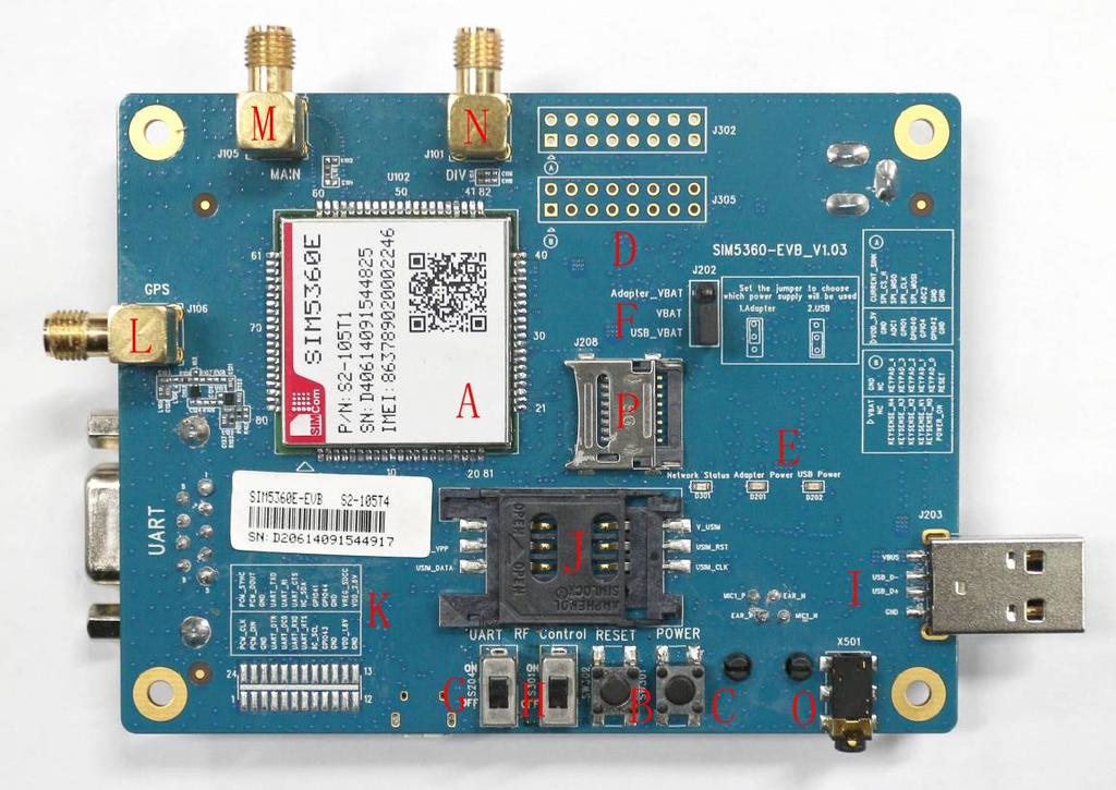
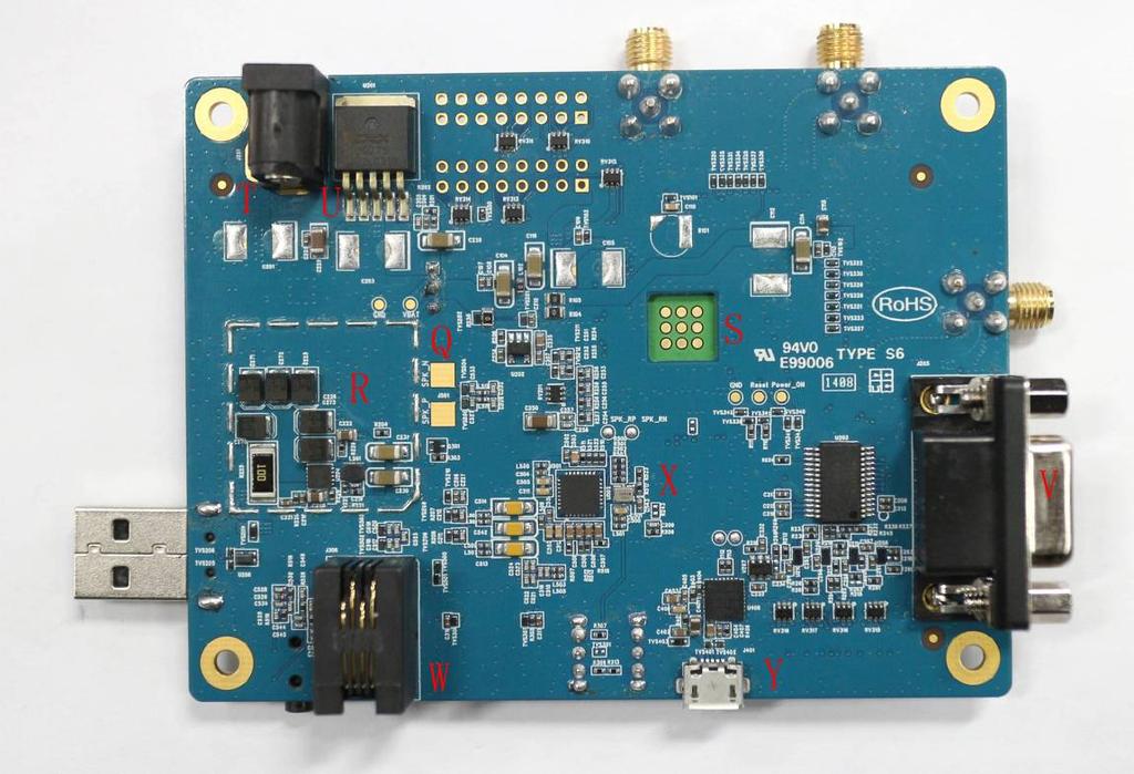
6 2 SIM5360 EVB SIM5360 EVB User Guide 5
7 Figure 1: EVB view Smart Machine Smart Decision A: SIM5360 module B: Reset keypad C: Power on/off keypad D: IO interface 1(including GPIO, ADC, SPI, etc) E: LED indicator(including network status,operating status) F: Power supply selection jumper G: UART enable/disable switch(if user wants to use UART, please switch it to ON at first.) H: RF enable/disable (flight mode) switch (Before the SIM5360 is powered on, please make sure that RF control switch is ON) I: USB connector J: SIM card socket K: IO interface 2(including PCM,GPIO, UART, I2C, etc) L: GPS/GLONASS antenna SMA M: Main antenna SMA N: Rx-diversity antenna SMA O: Headset interface P: SD card interface Q: Speaker interface R: USB DC-DC S: SIM5360 JTAG test point T: Adapter connector U: DC LDO V: UART interface for AT command transmitting, data exchanging W: Handset interface(rj-11) X: Audio codec (WM8960) Y: MicroUSB interface for SIM5360 (UART2 to USB, IC is Silabs Cp2103) SIM5360 EVB User Guide 6
8 The following figure shows block diagram of SIM5360 EVB. Level Transition S301 RF Control SW302 Reset SW301 POWER_ON MIC2 HPL MIC1 J202 All hardware Sub-interfaces included in SIM5360 EVB are described in detail in following chapters. SIM5360 EVB User Guide 7


9 3 EVB accessories Figure 2: EVB accessory A: USB to UART cable B: RF antenna C: USB cable D: 5V DC adapter E: GPS/GLONASS antenna F: RF antenna SIM5360 EVB User Guide 8


10 4 Accessory Interface 4.1 Power Interface Figure 3: Power selection jumper Table 2: Power supply Signal Input/Output Description Adapter_VBAT O 3.8V/2A DC source input USB_VBAT O 3.8V/0.5A DC source input VBAT I SIM5360 DC source input If user wants to use DC adapter as power supply, Adapter_VBAT should be connected to VBAT on J202 through a jumper as following figure shows. This board could be powered by USB bus. User should connect the USB pin. USB_VBAT is the USB power out.if user wants to use USB VBUS to power up the module, please connect connector VBAT with connector USB_VBAT as following figure shows.and disconnect Adapter_VBAT. SIM5360 EVB User Guide 9

11 4.2 Audio Interface Figure 4: Audio Interface J306 is the handset interface. X501 is the headset interface. NOTE: The MIC s polarity must be correct. Table 3: Earphone interface Pin Signal Input/Output Description 1 MIC1P I Positive microphone input 2 EAR_P O Positive receiver output 3 EAR_N O Negative receiver output 4 MIC1N I Negative microphone input Table 4: Headset interface Pin Signal I/O Description 5 GND Ground 6 HEADSET_MIC+ I Headset microphone input 7 HPH_L O Positive microphone output 8 HPH_R O Negative microphone output Speaker interface: Please refer Figure 1. Pin 1 and Pin 2 is the SPK_M and SPK_P on J501. NOTE: Audio cable must be away from the RF antenna, otherwise TDD noise may be occurred. SIM5360 EVB User Guide 10

12 4.3 SIM card interface Figure 5: SIM card socket Table 5: SIM card socket Pin Signal Input/Output Description USIM Card Power output automatic 1 V_USIM output on USIM mode,one is O 3.0V±10%, another is 1.8V±10%. Current is about 10mA. 2 USIM_RESET O USIM Card Reset 3 USIM_CLK O USIM Card Clock 4 GND Ground 5 SIM_VPP Not connect 6 USIM_DATA I/O USIM Card data I/O SIM5360 EVB User Guide 11
 for the application including an antenna.")

13 4.4 Antenna Interface Figure 6: Main and diversity Antenna connector Figure 7:GPS Antenna connector SIMCom strongly recommends additional matching components between the antenna and the RF output of SIM5360 RF PAD (Main: pin 59; Diversity: PIN 82; GPS: pin 79;) for the application including an antenna. Topology is a PI structure plus a serial element; components assume to be capacitors or inductors depending on the antenna matching. But if the pad is 50 Ohms and is connected to 50 Ohms load, the matching circuitry is not needed. The RF connection should be short enough to minimize losses and must have a characteristic impedance of 50 Ohms until F 2 GHz. SIMCom strongly recommends the micro strip line can be used. SIM5360 EVB User Guide 12


14 4.5 RS232 Interface Figure 8: Serial Port J205 is 9 pins standard RS232 UART interface. It can be connected to a PC directly. Table 6: Serial Interface Pin Signal I/O Description 1 DCD O Data carrier detection 2 TXD O Transmit data 3 RXD I Receive data 4 DTR I Data Terminal Ready 5 GND Ground 6 NC NC 7 RTS I Request to Send 8 CTS O Clear to Send 9 RI O Ring Indicator 4.6 Operating Status LED Figure 9: Status LED Table 7: Network status LED D301 Status Off On 800ms On/ Off Module Status Module is not running Module is running, or voice call is connected Module find the network and registered SIM5360 EVB User Guide 13

15 200ms On/ Off Data communication Smart Machine Smart Decision LED I/O Description D201 O ADAPTER power indicator D202 O USB power indicator 4.7 USB interface It is a normal 4Pin USB connector. Figure 10: USB Interface Table 8: USB interface Pin Signal I/O Description 1 USB_VBUS I 5V 2 USB_DM I/O D+ line 3 USB_ DP I/O D- line 4 GND Ground SIM5360 EVB User Guide 14
 ON : Normal mode OFF : Flight mode 3 RESET I Reset the module 4 PWRER_ON I Power on the module SIM5360 EVB User Guide")
16 4.8 Switch interface Figure 11: Switch Interface Table 9: Switch interface Switch Signal I/O Description 1 RS232 chip SHUTDOWN I UART switch 2 GPIO4 I RF switch (S301) ON : Normal mode OFF : Flight mode 3 RESET I Reset the module 4 PWRER_ON I Power on the module SIM5360 EVB User Guide 15


17 4.9 IO interface Figure 12: IO Interface SIM5360 EVB User Guide 16
18 Table 10: IO interface Smart Machine Smart Decision Signal I/O Description GPIO40 I/O GPIO POWER_ON I Power on the module RESET I Reset the module GPIO41 I/O GPIO GPIO43 I/O GPIO GPIO44 I/O GPIO VDD_3V O 3V power supply CURRENT_SINK I Current sink source ADC1 I ADC GPIO1 O Network status GPIO4 I RF control switch GPIO42 I/O GPIO SPI_CS_N O SPI Chip selection SPI_MISO (UART_RXD) I SPI Master input Slave output / Receive data of UART2 SPI_MOSI (UART_TXD) O SPI Master output Slave input / Transmit data of UART2 ADC2 I ADC KEYSENSE_N0 I Bit 0 for sensing key press on pad matrix KEYSENSE_ N1 I Bit 1 for sensing key press on pad matrix KEYSENSE_ N2 I Bit 2 for sensing key press on pad matrix KEYSENSE_ N3 I Bit 3 for sensing key press on pad matrix KEYSENSE_ N4 I Bit 4 for sensing key press on pad matrix KEYPAD_0 O Bit 0 drive to the pad matrix KEYPAD_1 O Bit 1 drive to the pad matrix KEYPAD_2 O Bit 2 drive to the pad matrix KEYPAD_3 O Bit 3 drive to the pad matrix KEYPAD_4 O Bit 4 drive to the pad matrix I2C_SDA I/O I2C data I2C_SCL O I2C clock PCM_DIN/GPIO0 I General input pin for module wake up interrupt. It also can be multiplexed as the PCM_DIN pin. PCM_SYNC/GPIO2 I General input pin. It also can be multiplexed as the PCM_SYNC pin. SIM5360 EVB User Guide 17

19 PCM_CLK/GPIO3 PCM_DOUT/GPIO5 O O Smart Machine Smart Decision General output pin. It also can be multiplexed as the PCM_CLK pin. General output pin. It also can be multiplexed as the PCM_DOUT pin SD card interface Figure 13: SD card socket J208 is the SD card interface. Table 11: SD card socket Pin Signal Input/Output Description 1 SD_D2 I/O Data line 2 2 SD_D3 I/O Data line 3 3 SD_CMD O Command line 4 VREG_SDCC O Power supply for SD card 5 SD_CLK O Clock line 6 GND Ground 7 SD_D0 I/O Data line 0 8 SD_D1 I/O Data line 1 SIM5360 EVB User Guide 18

20 4.10 UART2 to MicroUSB interface Figure 14: MicroUSB interface J401 is 5 pins standard MicroUSB interface. It can be connected to a PC directly. The following figure is the uart to USB circuit of SIM5360-EVB. Figure 15: Uart to USB circuit SIM5360 EVB User Guide 19

21 5 EVB and accessory equipment At normal circumstance, the EVB and its accessories are equipped as the Figure below. Figure 16: EVB and accessory equipment 6 Quickly start 6.1 Running There are two ways to provide power supply to SIM5360 module: one is to use the 5V power supply provided in the EVB kit; the other is to use USB port of personal computer. (1) When user use the power supply, if user insert 5V DC source adapter, user should connect ADAPTER_VBAT pin and VBAT pin on the EVB board; then insert a valued SIM card and check if the antenna is connected, and make sure that RF control switch is set to ON; finally press the on/off switch for about 1 second, and then SIM5360 module will begin running. (2) Another option is to use USB port of Computer as power supply. To do so, user need to connect USB_VBAT pin and VBAT pin on the EVB board, and make sure that RF control switch is set to ON. Firstly insert the sim card and connect the antenna, then connect the PC with USB-to-USB cable and press the Power_ON button for one second, then SIM5360 will start running. SIM5360 EVB User Guide 20
22 User can see the light on the EVB flashing at a certain frequency about 1.25Hz. By the state, user can judge whether the EVB and SIM5360 is running or not. No function and test can be executed if user has not connected necessary accessories. NOTE: This EVB board supports USB power supply when user connects USB_VBAT and VBAT together. 6.2 Installing Driver There are 3 ways to connect the module to user s computer and communicate via HyperTerminal: (1) Using USB-TO-USB cable; (2) Using UART-TO-USB cable; (3) Using UART-TO-UART cable. In the first case, user need install the module USB driver, which can be got from our FAE or sales; For the UART to USB driver, user may get it from the CD in the EVB kit; If user use UART to UART cable, there are certain points to be noticed. One can use UART to UART cable in EVB kit, if the customers want to use their own UART to UART cable, please make sure that the pin sequences of it is same as those of cable in EVB kit, pin sequences of which are shown in Figure Connecting Net and calling Once user installs the driver, user can follow steps below to connect to Network. (1) When user use a UART-UART cable, user need to connect the serial port line to the serial port, open the HyperTerminal (AT command windows) on user s Personal computer. The location of the HyperTerminal in windows2000/xp/vista can be found from START accessory communication HyperTerminal. Please set the correct Baud Rate and COM port number, the Baud Rate of SIM5360 is , and the COM port number is based on which UART port user s serial port line is inserted, user should select the port such as COM1 or COM2 etc. (2) Connect the antenna to the SIM5360 module using an antenna transmit line, insert SIM card into the SIM card holder, and insert handset into its sockets. (3) Follow the steps of running which has been mentioned above in Sector 5.1, power on the system, type the AT command from the HyperTerminal, and then the SIM5360 module will execute its corresponding function. For example, if user type AT, then it should respond OK ; if user type ATI, it should display product identification information. (4) If user want to use USB to USB cable, user need to connect the cable to USB port of the module and the computer, then follow step 1~3. SIM5360 EVB User Guide 21
23 (5) If user use UART to USB cable, user need to connect the cable to module serial port and the USB port of the computer, then follow step 1~ Downloading Connect the USB port line to the USB port, connect the direct current source adapter, run the download program, and choose the correct image, please follow the QDL downloading menu for the operation. Update procedure is described in the figure below. START Module power on Double click QDL.exe, update begin Connect module USB slot and PC by USB cable Waiting until download finish, Install module driver on windows OS. QDL quit out automatically Copy new firmware into QDL data folder Update success Close all app software which use USB virtual ports Figure 17: USB interface update procedure 6.5 Turning off Press the POWER_ON for about 1 second, SIM5360 module will be turned off. NOTE: If user uses USB to power on the module, just disconnect the USB cable to turn off. SIM5360 EVB User Guide 22
24 Contact us: Shanghai SIMCom Wireless Solutions Ltd. Add: Building A,SIM Technology Building,No.633,Jinzhong Road,Changning Disdrict,Shanghai P.R. China Tel: Fax: URL: SIM5360 EVB User Guide 23
SIM5350_EVM_User_Guide _V1.00
 SIM5350_EVM_User_Guide _V1.00 Document Title: SIM5350_EVM_User_Guide Version: 1.00 Date: Status: Document Control ID: Release SIM5350_EVM_User_Guide_V1.00 General Notes SIMCom offers this information as
Development Kit Manual SIM900D-EVB_UGD_V1.01
 Development Kit Manual SIM900D-EVB_UGD_V1.01 Document Title: SIM900D EVB User Guide Version: 1.01 Date: 2010-7-1 Status: Document Control ID: Release SIM900D-EVB_UGD_V1.01 General Notes Simcom offers this
Development Kit Manual SIM305-EVB_UGD_V1.01
 Development Kit Manual SIM305-EVB_UGD_V1.01 Document Title: SIM305 EVB User Guide Version: 1.01 Date: 2007-09-30 Status: Document Control ID: Release SIM305-EVB_UGD_V1.01 General Notes SIMCom offers this
SIM800H&L_EVM_User Guide _V1.00
 SIM800H&L_EVM_User Guide _V1.00 Document Title: SIM800H&L_EVM_User Guide Version: 1.00 Date: Status: Document Control ID: Release SIM800H&L_EVM_User Guide_V1.00 General Notes SIMCom offers this information
Development Kit Manual. SIM908 EVB kit_user Guide_V1.00
 Development Kit Manual SIM908 EVB kit_user Guide_V1.00 Document Title: Version: 1.00 Date: 2011-08-15 Status: Document Control ID: Release SIM900_EVB kit_user Guide_V1.00 General Notes SIMCom offers this
Mini PCIe_EVB kit_ User Guide_V1.00
 Mini PCIe_EVB kit_ User Guide_V1.00 Document Title: Mini PCIe EVB kit User Guide Version: 1.00 Date: 2014-05-05 Status: Document Control ID: Release Mini PCIe _EVB kit_user Guide_V1.00 General Notes SIMCom
M10. Quectel Cellular Engine. EVB User Guide M10_EVB_UGD_V1.00
 M10 Cellular Engine EVB User Guide M10_EVB_UGD_V1.00 Document Title M10 EVB User Guide Version 1.00 Date 2009-06-27 Status Document Control ID Release M10_EVB_UGD_V1.00 General Notes offers this information
SIM508 EVB USER GUIDE
 SIM508 EVB USER GUIDE Ltd. 7 th Jul. 2006 Document Name: SIM508 EVB User Guide Version: 1.02 Date: 2006-07-07 Doc ID: SIM508-EVB_UGD_V1.02 Status: Released General Notes Simcom offers this information
SIM28_EVB kit_user Guide_V1.02
 SIM28_EVB kit_user Guide_V1.02 Document Title: Version: 1.02 Date: 2012-03-30 Status: Document Control ID: Release SIM28_EVB Kit_User Guide_V1.02 General Notes SIMCom offers this information as a service
Audio LINE-IN input application. AN_SIM900_Audio LINE-IN Input_V1.01
 Audio LINE-IN input application AN_SIM900_Audio LINE-IN Input_V1.01 Document Title: Audio LINE-IN input application Version: 1.01 Date: 2010-04-07 Status: Document Control ID: Release AN_SIM900_Audio LINE-IN
SIM908_Reference Design Guide _Application Note_V1.00
 SIM908_Reference Design Guide _Application Note_V1.00 Document Title: SIM908 Reference Design Guide Version: 1.00 Date: 2011-08-10 10Status: Document Control ID: Released SIM908_ Reference Design Guide_Application
SIM900 Reference Design Guide. SIM900_AN_ Reference Design Guide_V1.01
 SIM900 Reference Design Guide SIM900_AN_ Reference Design Guide_V1.01 Document Title: SIM900 Reference Design Guide Version: 1.01 Date: 2010-01-27 10Status: Document Control ID: Released SIM900_AN_ Reference
SIMCOM WCDMA Wireless Module. xx_sleep_mode_application_note
 SIMCOM WCDMA Wireless Module SIM5xxx_Sleep_ xx_sleep_mode_application_note Document Title: SIM5xxx_ Sleep_Mode _Application_Note Version: 1.02 Date: 2011-08-16 Status: Document Control ID: Release AN SIM5xxx_Sleep_Mode_Application_Note_V1.02
GSM EVB User Guide. GSM/GPRS/UMTS/HSPA/NB-IoT Module Series. Rev. GSM_EVB_User_Guide_V3.4. Date:
 GSM/GPRS/UMTS/HSPA/NB-IoT Module Series Rev. GSM_EVB_User_Guide_V3.4 Date: 2017-03-03 www.quectel.com Our aim is to provide customers with timely and comprehensive service. For any assistance, please contact
UART Application Note
 UART Application Note Document Title: SIM52xx Application Note Version: 0.01 Date: 2011-06-22 Status: Document Control ID: Release SIM52xx Application_Note_V0.01 General Notes Simcom offers this information
SIMCom_SIM800H_EAT_flash_Tool _User Manual_V1.01
 SIMCom_SIM800H_EAT_flash_Tool _User Manual_V1.01 Document Title: SIMCom_SIM800H_EAT_flash_Tool_User Manual Version: 1.01 Date: 2013-08-27 10Status: Document Control ID: Draft AN_SIMCom_SIM800H_EAT_flash_Tool_App
UMTS<E EVB User Guide
 UMTS<E EVB User Guide UMTS/HSPA/LTE Module Series Rev: UMTS<E_EVB_User_Guide_V1.0 Date: 2015-03-03 www.quectel.com Our aim is to provide customers with timely and comprehensive service. For any assistance,
UART. SIM5360 UART Multiplexer Application Note. SIM5360_UART_Multiplexer_Application_Note_V
 UART SIM5360 UART Multiplexer Application Note 1 Document Title: SIM5360 UART Multiplexer Application Note Version: 0.01 Date: 2014-05-30 Status: Document Control ID: Release SIM5360_UART_Multiplexer_Application_Note_V0.01
Development KIT for TM2Q GSM/GPRS module. User s Manual v1.1
 Development KIT for TM2Q GSM/GPRS module User s Manual v1.1 TABLE OF CONTENTS 1. Basic Safety Requirements...4 2. General Information...5 2.1. INTRODUCTION...5 2.2. ABOUT THIS DOCUMENT...5 2.3. LEGAL NOTICE...5
SIMCom_3G_PCM_Application Note_V1.04
 SIMCom_3G_PCM_Application Note_V1.04 Document Title: SIMCom_3G_PCM_Application Note Version: 1.04 Date: Status: Document Control ID: Release SIMCom_3G_PCM_Application Note _V1.04 General Notes SIMCom offers
Firmware Upgrade Tool Lite User Guide. Firmware_Upgrade_Tool_Lite_V1.1
 Firmware Upgrade Tool Lite User Guide Firmware_Upgrade_Tool_Lite_V1.1 Document Title Firmware Upgrade Tool Lite User Guide Version 1.1 Date 2010-12-24 Status Document Control ID Release Firmware_Upgrade_Tool_Lite_V1.1
SIMCOM WCDMA Wireless Module SIM5xxx PCM Application Note
 SIMCOM WCDMA Wireless Module SIM5xxx PCM Application Note Document Title: SIM5xxx PCM Application Note Version: 1.03 Date: 2011-08-26 Status: Document Control ID: Release AN_ SIM5xxx PCM Application Note
/
 WWW.INFOPULSAS.LT / info@infopulsas.lt Development board for Sierra SL6087and XM01100 Technical Specification TABLE OF CONTENTS 1 Introduction... 3 2 Development Board top view... 3 3 Development Board
User Guide. Release r01
 Release r01 Note This device was developed for the purpose of communication in an office environment. It is intended solely for our industrial clients for physical integration into their own technical
LTE OPEN EVB User Guide
 LTE OPEN EVB User Guide LTE Module Series Rev. LTE_OPEN_EVB_User_Guide_V1.1 Date: 2018-03-19 Status: Released www.quectel.com Our aim is to provide customers with timely and comprehensive service. For
UART Dload Application Note
 UART Dload Application Note Document Title: SIM52xx UART Dload Application Note Version: 0.02 Date: 2013-02-26 Status: Document Control ID: Release SIM52xx_UART_Dload_Application_Note_V0.02 General Notes
Development KIT for TM2 GPRS modem User manual 1.2. Development KIT. Development KIT for TM2 GSM/GPRS modem User s manual 1.2
 Development KIT Development KIT for TM2 GSM/GPRS modem User s manual 1.2 1 Contents Attention!... 3 1. Basic Safety Requirements... 4 2. General Information... 5 2.1 Introduction... 5 2.2 About this document...
UART Application Note. SIM5XXX UART Application Note 1
 UART Application Note SIM5XXX UART Application Note 1 Document Title: SIM5XXX UART Application Note Version: 0.02 Date: 2013-02-26 Status: Document Control ID: Release SIM5XXX_UART_Application_Note_V0.02
GWBMA0x Bluetooth Audio module
 GWBMA0x Bluetooth Audio module Data sheet version 0.9 draft GWBMA0X DATASHEET 0.9 GIGAWIT 1 Introduction GWBMA1X is a high performance Bluetooth audio module, It provides various type of wireless audio
User Guide. Date Apr BlueEva+C11/G2. Stollmann. E + V GmbH. User Guide
 Version r02 Date Apr 2009 Author: ta Date saved: 06.04.09 Ref: BlueEva+C11G2_User_Guide_r02.doc Revision: r02 Page 1 of 22 Note This device was developed for the purpose of communication in an office environment.
UMTS<E EVB User Guide
 UMTS<E EVB User Guide UMTS/HSPA/LTE Module Series Rev. UMTS<E_EVB_User_Guide_V2.0 Date: 2017-01-12 www.quectel.com Our aim is to provide customers with timely and comprehensive service. For any assistance,
GSM. Quectel Cellular Engine. Firmware Update Application Note. Fw_Update_Application_Note_V3.1
 GSM Cellular Engine Firmware Update Application Note Fw_Update_Application_Note_V3.1 Document Title Firmware Update Application Note Version 3.1 Date 2012-03-08 Status Document Control ID Released Fw_Update_Application_Note_V3.1
M10-TE-A. Quectel Cellular Engine. Hardware Design M10-TE-A_HD_V1.01
 M10-TE-A Cellular Engine Hardware Design M10-TE-A_HD_V1.01 Document Title M10-TE-A Hardware Design Version 1.01 Date 2009-10-26 Status Document Control ID Release M10-TE-A_HD_V1.01 General Notes offers
Delta Package Update Application Note
 Delta Package Update Application Note Document Title: SIM52xx Delta Package Update Application Note Version: 0.01 Date: 2011-06-22 Status: Document Control ID: Release SIM52xx_Delta_Package_Update_Application_Note_V0.01
Quectel Cellular Engine
 Cellular Engine GSM Module Firmware Upgrade User Guide for Production GSM_Module_FW_Upgrade_ User_Guide_for_Production_V1.0 Document Title GSM Module Firmware Upgrade User Guide for Production Version
UMTS<E EVB User Guide
 UMTS<E EVB User Guide UMTS/HSPA/LTE Module Series Rev. UMTS<E_EVB_User_Guide_V2.1 Date: 2017-12-27 Status: Released www.quectel.com Our aim is to provide customers with timely and comprehensive service.
xpico 200 Series Evaluation Kit User Guide
 xpico 200 Series Evaluation Kit User Guide This guide describes how to setup the xpico 200 series evaluation kit and provides the information needed to evaluate the included xpico 240 or xpico 250 embedded
CORE6410 Process Card
 CORE6410 Process Card Features Dimensions: 60 x 60 x 2.8 mm, 8 layer. ARM11 Samsung S3C6410, ARM1176JZF-S, up to 667MHz 256MByte MoblieDDR, 266MHz 1GByte NAND Flash(support 8GByte NAND Flash) inand Flash
NDB-C0706A Dual Mode Bluetooth Module
 NDB-C0706A Dual Mode Bluetooth Module 1 Device Overview 1.1 Description This module is designed with Cypress CYW20706 (previously Broadcom BCM20706) dual mode Bluetooth 5.0 SoC. CYW20706 features 96 MHz
UB603 Four Band GSM/GPRS Module. Hardware Manual. July 2010
 UB603 Four Band GSM/GPRS Module Hardware Manual July 2010 1 / 26 1 Preface 1.1 Purpose of this document UB603 cellular module can be used in GSM850/GSM900/DCS1800/PCS1900 networks. The application ranges
SIM7100_SIM7500_SIM7600 LBS_Application Note_V1.00
 SIM7100_SIM7500_SIM7600 LBS_Application Note_V1.00 Series SIM7100_SIM7500_SIM7600 Series LBS_Application Note_V1.00 1 2017-09-26 Document Title: SIM7100_SIM7500_SIM7600 Series LBS_Application Note Version:
AT Commands Set SIM20_ATC_V1.02
 AT Commands Set SIM20_ATC_V1.02 Document Title: SIM20 SRD AT Command Set Version: 1.02 Date: 2010/1/10 Status: Document Control ID: Release SIM20_ATC_V1.02 General s SIMCOM offers this information as a
AVL-300 3G USER MANUAL. TrackingTheWorld.com. Automatic Vehicle Tracking Device
 TrackingTheWorld.com AVL-300 3G Automatic Vehicle Tracking Device USER MANUAL Document Title AVL-300 3G User manual Version 1.02 Date 2015-9-10 Status Document Control ID Release TTW-AVL300-3G-UM001 General
M-5360A imx537 Cortex A8 System on Module User Guide
 M-5360A imx537 Cortex A8 System on Module User Guide Version 1.0 Copyright Artila Electronics Co., Ltd. All Rights Reserved. Table of Contents 1. Introduction... 1 2. Layout... 3 3. M-5360A B2B Connector
SIM5320_Hardware Design_V1.02
 SIM5320_Hardware Design_V1.02 Document Title SIM5320 Hardware Design Version 1.02 Date Status Document Control ID Release SIM5320_Hardware Design_V1.02 General Notes SIMCom offers this information as a
3 Application Board: GM862-S1
 1vv0300565 SR8.56.005, Rev. ISSUE#5-05/02/02 3 Application Board: GM862-S1 In order to use the Telit GM862 module as a stand-alone product, Telit supplies an Application Board (namely Telit S1 Board) that
WT12 EVALUATION KIT DATA SHEET. Monday, 09 September Version 1.7
 WT12 EVALUATION KIT DATA SHEET Monday, 09 September 2013 Version 1.7 VERSION HISTORY Version Comment 1.0 MSa 1.1 NM 1.2 PR 1.3 MSa 1.4 MSa 1.5 MSa 1.6 MSa 1.7 Table 2 corrected TABLE OF CONTENTS WT12 Evaluation
Figure 1. CP2108 USB-to-Quad UART Bridge Controller Evaluation Board
 CP2108 EVALUATION KIT USER S GUIDE 1. Introduction The CP2108 is a highly integrated USB-to-Quad-UART Bridge Controller providing a simple solution for updating RS-232/RS-485 designs to USB using a minimum
Development Kit User Guide. AirPrime HL6 and HL8 Series
 AirPrime HL6 and HL8 Series 4114877 2.1 March 10, 2014 Important Notice Due to the nature of wireless communications, transmission and reception of data can never be guaranteed. Data may be delayed, corrupted
CF Plug-In. Evaluation Board User Guide. Bulletin Revision Date
 CF Plug-In Evaluation Board User Guide Bulletin Revision Date JA03-EBUG 00 06 Dec 2017 Table of Contents I. Introduction------------------------------------------------------------------------- 2 Scope
SBC3100 (Cortex-A72) Single Board Computer
 Single Board Computer") (Cortex-A72) Single Board Computer Ultra High Performance SBC with RK3399 (Cortex-A72 x2 + Cortex-A53 x4) @ 2Ghz : Single Board Computer H310: Input (receiver) Module : Output (display) Module D120: 4xCOM
(Cortex-A72) Single Board Computer Ultra High Performance SBC with RK3399 (Cortex-A72 x2 + Cortex-A53 x4) @ 2Ghz : Single Board Computer H310: Input (receiver) Module : Output (display) Module D120: 4xCOM
GSM 4 click MIKROE Weight: 33 g
 GSM 4 click MIKROE-2388 Weight: 33 g GSM 4 click is a mikrobus add-on board that features the u-blox SARA-G3 series 2.5G GSM/GPRS cellular quad-band module. The SARA-G3 module has a miniature LGA (Land
4G LTE-E click (Europe)
") 4G LTE-E click (Europe) MIKROE-2527 Weight: 36 g 4G LTE-E click carries the LARA-R211 multi-mode cellular module from u-blox. The board is designed to use 5V power supply. I/O voltage levels could be 3.3V
4G LTE-E click (Europe) MIKROE-2527 Weight: 36 g 4G LTE-E click carries the LARA-R211 multi-mode cellular module from u-blox. The board is designed to use 5V power supply. I/O voltage levels could be 3.3V
PremierWave 2050 Enterprise Wi-Fi IoT Module Evaluation Kit User Guide
 PremierWave 2050 Enterprise Wi-Fi IoT Module Evaluation Kit User Guide Part Number 900-765-R Revision A February 2016 Intellectual Property 2016 Lantronix, Inc. All rights reserved. No part of the contents
Development Kit User Guide. AirPrime SL Series
 AirPrime SL Series WA_DEV_SL6087_UGD_003 003 September 24, 2010 Important Notice Due to the nature of wireless communications, transmission and reception of data can never be guaranteed. Data may be delayed,
BlueTooth Carrier Board CAB/BT1
 BlueTooth Carrier Board CAB/BT1 User Manual Content 1 INTRODUCTION...4 1.1 Conventions used in this Document...4 1.2 Checklist...5 1.3 Main Features...6 2 BOARD LAYOUT...7 3 BOARD COMPONENTS...8 3.1 Reset
EVK-NINA-B2. Evaluation Kit for NINA-B2 modules. User Guide
 EVK-NINA-B2 Evaluation Kit for NINA-B2 modules User Guide Abstract This document describes how to set up the EVK-NINA-B22x evaluation kits to evaluate NINA-B2 series stand-alone Bluetooth dual-mode modules.
User Manual Sample. (English version)
") BT-2001 v2.5 User Manual Sample (English version) Man & Tel Co., Ltd. [www.manntel.com] SMD-BT2-E025a Copyright Man&Tel 2004 Page 1of 10 Contents I. Hardware 1. Hardware Overview and Functions 3 2. Hardware
BT-2001 v2.5 User Manual Sample (English version) Man & Tel Co., Ltd. [www.manntel.com] SMD-BT2-E025a Copyright Man&Tel 2004 Page 1of 10 Contents I. Hardware 1. Hardware Overview and Functions 3 2. Hardware
SIM900 Hardware Design Guide Jeffrey Song, 2010
 SIM900 Hardware Design Guide Jeffrey Song, 2010 SIM900 Hardware Overview (Top View) Application: M2M Smart phone Tracker The GPRS/GSM engine for the global market. Quad-band : GSM850, EGSM900, DCS1800,
Hardware Interface Description
 Hardware Interface Description Java Box Terminal Motorola G24 Cellular + GPS Engine Version: 02.01A Java Box Terminal_HD_V02.01 17.JUL.2008 1. Key Features of the Java Box Terminal Feature Implementation
AL582C-EVB-A0 Evaluation Board
 AL582C-EVB-A0 Evaluation Board User Manual Version 1.0 INFORMATION FURNISHED BY AVERLOGIC IS BELIEVED TO BE ACCURATE AND RELIABLE. HOWEVER, NO RESPONSIBILITY IS ASSUMED BY AVERLOGIC FOR ITS USE, OR FOR
WIZ-SM10 Datasheet. ( Version 0.1 ) 2010 WIZnet Co., Ltd. All Rights Reserved. For more information, visit our website at
 2010 WIZnet Co., Ltd. All Rights Reserved. For more information, visit our website at") WIZ-SM0 Datasheet ( Version 0. ) 00 WIZnet Co., Ltd. All Rights Reserved. For more information, visit our website at http://www.wiznet.co.kr WIZ-SM0 Datasheet (WIZnet Co., Ltd.) Document Revision History
WIZ-SM0 Datasheet ( Version 0. ) 00 WIZnet Co., Ltd. All Rights Reserved. For more information, visit our website at http://www.wiznet.co.kr WIZ-SM0 Datasheet (WIZnet Co., Ltd.) Document Revision History
RoBoard RB-100 Manual V2.00 The Heart of Robotics. Jan 2009 DMP Electronics Inc
 RoBoard RB-100 Manual V2.00 The Heart of Robotics Jan 2009 DMP Electronics Inc Copyright The information in this manual is subject to change without notice for continuous improvement in the product. All
Rayson Bluetooth Module
 Rayson Bluetooth Module Low Energy Smart Module Features Bluetooth standard V4.0 conformity. CSR000/00 chip Programmable general purpose PIO controller : Switch-mode power supply. IC for EEPROM and ICs
Technical Document. Model: F120 Name: F120 PCBA Service Manual No.: Version: V1.0. Check Sign. Standard Approved
 Technical Document Model: F120 Name: F120 PCBA Service Manual No.: Version: V1.0 Drawn Check Sign wanglinwen Standard Approved Amendment Records No. Version Drawn/ Brief Date Reason Amender Introduction
EB35W1M Bluetooth Stereo Audio Module
 EB35WM Bluetooth Stereo Audio Module EB35WM Datasheet Product Description The EB35WM Bluetooth stereo audio module is based on CSR BC05 chip BC57E687. The module has been integrated with most of the peripheral
V2403 Quick Installation Guide
 V2403 Quick Installation Guide Edition 1.0, September 2015 Technical Support Contact Information www.moxa.com/support Moxa Americas: Toll-free: 1-888-669-2872 Tel: 1-714-528-6777 Fax: 1-714-528-6778 Moxa
EZL-200F Application Notes (003) Serial Interface (RS232/RS422/RS485)
 Serial Interface (RS232/RS422/RS485)") Application Notes (003) Serial Interface (RS232/RS422/RS485) Version 2.0 Sollae Systems Co., Ltd. 1. Overview supports three serial interfaces: RS232, RS422, and RS485. You can select the interface you
Application Notes (003) Serial Interface (RS232/RS422/RS485) Version 2.0 Sollae Systems Co., Ltd. 1. Overview supports three serial interfaces: RS232, RS422, and RS485. You can select the interface you
BG96 PPP Application Note
 LTE Module Series Rev. BG96_PPP_Application_Note_V1.0 Date: 2018-01-31 Status: Released www.quectel.com Our aim is to provide customers with timely and comprehensive service. For any assistance, please
LPC2148 DEV BOARD. User Manual.
 LPC2148 DEV BOARD User Manual www.coineltech.com www.coineltech.com Designed by CoiNel Technology Solutions LLP No-816, 2 nd Floor, 4 th B Cross, 9 th A Main, RPC Layout, Vijaynagar, Bangalore-560040 State:
Smart Machine Smart Decision. R700_User Guide_V1.05 1
 R700_User Guide_V1.05 R700_User Guide_V1.05 1 Document Title R700_User Guide Version 1.05 Date Status Document Control ID Released R700_User Guide_V1.05 General Notes SIMCom offers this information as
EC2x&EG9x&EM05 PPP Application Note
 EC2x&EG9x&EM05 PPP Application Note LTE Module Series Rev. EC2x&EG9x&EM05_PPP_Application_Note_V1.0 Date: 2017-12-08 Status: Released www.quectel.com Our aim is to provide customers with timely and comprehensive
Product Datasheet: DWM1001-DEV DWM1001 Module Development Board. Key Features and Benefits
 Product Datasheet: DWM1001-DEV DWM1001 Module Development Board Plug-and-Play Development Board for evaluating the performance of the Decawave DWM1001 module Easily assemble a fully wireless RTLS system,
GM8126 EVB. User Guide Rev.: 1.1 Issue Date: July 2011
 GM8126 EVB User Guide Rev.: 1.1 Issue Date: July 2011 REVISION HISTORY Date Rev. From To Feb. 2011 1.0 - Original Jul. 2011 1.1 - Modified Section 3.1 Copyright 2011 Grain Media, Inc. All Rights Reserved.
Document Name : User Manual for SC10B : RS232 to Bluetooth Converter.
 Document Name : User Manual for SC10B : RS232 to Bluetooth Converter. SC10B is Bluetooth V.2.0-certified and is backward compatible with v1.1/1.2 devices. You can connect between your computers (Master)
Installation and Configuration Quick Guide R3000. Industrial Dual SIM Cellular VPN Router 2 Eth + 1 RS RS USB Host.
 Package Contents Installation and Configuration Quick Guide Before installing your R3000 Router, verify the kit contents as following. 1 x Robustel R3000 Industrial Dual SIM Cellular VPN Router (GPS/WiFi
EZ864 G. Telit Cellular GSM/UMTS Engine. Hardware guide Version: Update: 27. APR.2009 EZ864 G_Hardware Guide_V
 EZ864 G Telit Cellular GSM/UMTS Engine Hardware guide Version: 04.01 Update: 27. APR.2009 EZ864 G_Hardware Guide_V4. - 1 - Hardware Interface Description 1. Hardware Features of the EZ864 G Feature Implementation
S2C Link Accessory Kit Datasheet
 S2C Link Accessory Kit Datasheet Part Number: NL-S2CK NimbeLink Corp Updated: May 2018 PN 30230 rev 3 NimbeLink Corp. All Rights Reserved 1 Table of Contents Introduction 3 Overview 3 Technical Specifications
SIM20_AT Command Manual_V1.04
 SIM20_AT Manual_V1.04 Command Document Title: SIM20 AT Command Manual Version: 1.04 Date: 2010-08-30 Status: Document Control ID: Release SIM20_AT Command Manual_V1.04 General s SIMCom offers this information
GEA M6425 IB Main Board. Cable Map Manual
 GEA M6425 IB Main Board Cable Map Manual REV A ATE REVISION CHANGE DESCRIPTION 20/09/10 - Creation 21/09/10 A Added features Page 1 of 13 Summary GEA MB Cable Map Overview...3 Micro SD Connections...4
GSM Interfacing Board
 Campus Component Pvt. Ltd. DISCLAIMER Information furnished is believed to be accurate and reliable at the time of publication. However, Campus Component Pvt. Ltd. assumes no responsibility arising from
Preliminary. PACKAGE - 28-pin MLP (5mm X 5mm) Example Circuit Diagram CP V. 48MHz Oscillator. USB Function Controller 512B EEPROM
 Example Circuit Diagram CP V. 48MHz Oscillator. USB Function Controller 512B EEPROM") Preliminary Single-Chip USB to UART Bridge SINGLE-CHIP USB to UART DATA TRANSFER - Integrated USB Transceiver; No External Resistors Required - Integrated Clock; No External Crystal Required - Integrated
Preliminary Single-Chip USB to UART Bridge SINGLE-CHIP USB to UART DATA TRANSFER - Integrated USB Transceiver; No External Resistors Required - Integrated Clock; No External Crystal Required - Integrated
Bluetooth TO Serial CONVERTER E-P132-B
 Bluetooth TO Serial CONVERTER E-P132-B 1 Table of Contents Introduction..3 Package checklist...4 Product Specification...5 Product Panel Views Description...6 Product Views. 6 DC-In Power Outlet 6 Antenna
EZ864 UMTS Terminal Telit Cellular GSM Engine
 EZ864 UMTS Terminal Telit Cellular GSM Engine Version: 01.01 EZ864 UMTS Terminal_HD_V01.01 06.Mar.2008-1 - Hardware Interface Description 1. Hardware Features of the EZ864 UMTS Terminal Feature Implementation
Cytron USB to UART Converter UC00A
 Cytron USB to UART Converter UC00A User s Manual V1.1 August 2009 Information contained in this publication regarding device applications and the like is intended through suggestion only and may be superseded
xpico 110 Wired Device Server Module Evaluation Kit User Guide
 xpico 110 Wired Device Server Module Evaluation Kit User Guide Part Number 900-788-R Revision A April 2017 Intellectual Property 2017 Lantronix, Inc. All rights reserved. No part of the contents of this
WiFi and Ethernet Shield With WiFi Audio
 WiFi and Ethernet Shield With WiFi Audio User Manual Rev 1.0 MAY 25, 2013 Copyright 2013 HISTORY Version Date Description Author K8 Document No.: WMB20130110 Page 2 of 15 INDEX Features...5 1.1. Parameters...6
4G LTE E click (Europe)
") 4G LTE E click (Europe) PID: MIKROE-2527 4G LTE-E click carries the LARA-R211 multi-mode cellular module from u-blox. The board is designed to use 5V power supply. I/O voltage levels could be 3.3V or 5V.
4G LTE E click (Europe) PID: MIKROE-2527 4G LTE-E click carries the LARA-R211 multi-mode cellular module from u-blox. The board is designed to use 5V power supply. I/O voltage levels could be 3.3V or 5V.
CMS-8GP32. A Motorola MC68HC908GP32 Microcontroller Board. xiom anufacturing
 CMS-8GP32 A Motorola MC68HC908GP32 Microcontroller Board xiom anufacturing 2000 717 Lingco Dr., Suite 209 Richardson, TX 75081 (972) 994-9676 FAX (972) 994-9170 email: Gary@axman.com web: http://www.axman.com
Wi125 Evaluation Kit User Manual
 Wi125 Evaluation Kit User Manual Issue: R01 Available at Digi-Key www.digikey.com Bulletin SG172-DKUM Revision R01 Date 06 May 2010 Table of Contents 1. Introduction 3 2. Wi125 Evaluation Board Overview
Bluetooth to RS-232 Converter. RT-132B Bluetooth Adaptor Operation Manual
 Bluetooth to RS-232 Converter RT-132B Bluetooth Adaptor Operation Manual First Edition, Nov 2007 Table of Contents 1. Introduction.. 2 2. Package checklist.. 3 3. Product Specification... 4 4. Product
SIM300 hardware application note V1.06
 SIM300 hardware application note V1.06 Excelpoint System Feb-26-2006 Version 1.06 Drafter: Charley Yang Reference: SIM300_HD_V1.06.pdf 16 1506 Tel852-2503 2212, Fax852-2503 1558 19 0823 Tel010-6580 2113/4/5/6,
SIM5215&SIM5216_Hardware_Design _V2.02
 SIM5215&SIM5216_Hardware_Design _V2.02 Document Title SIM5215&SIM5216 Hardware Design Version 2.02 Date Status Document Control ID Release SIM5215&SIM5216_Hardware Design_V2.02 General Notes SIMCom offers
EVK-NINA-W13. Evaluation Kit for NINA-W13 modules. User Guide. Abstract
 EVK-NINA-W13 Evaluation Kit for NINA-W13 modules User Guide Abstract This document describes how to set up the EVK-NINA-W13x evaluation kits to evaluate NINA-W13 series stand-alone Wi-Fi modules. It also
GWK5Mx 2.4GHz Wireless Audio Module
 GWK5Mx 2.4GHz Wireless Audio Module 1. General Description GWK5Mx is the module version of Gigawit GWK5 family wireless digital audio products. GWK5MO is 0dBm and GWK5MP is 18dBm, it can be easily integrate
Bluetooth to RS-232&RS422/485. EX-9132B/BI Bluetooth Adapter Operation Manual
 Bluetooth to RS-232&RS422/485 EX-9132B/BI Bluetooth Adapter Operation Manual First Edition, Jun 2008 Table of Contents 1. Introduction 2 2. Package checklist 3 3. Product Specification 4 4. Product Panel
EXL x240 Graphic LCD Smart Module 3,8 SHORT FORM TECHNICAL SPECIFICATIONS. Via di Corticella, Bologna, Italy
 320x240 Graphic LCD Smart Module 3,8 SHORT FORM TECHNICAL SPECIFICATIONS www.exelmicroel.it Via di Corticella, 201 40128 - Bologna, Italy Tel: +39 051 6380211 Fax: +39 051 6380226 exelbo@exelmicroel.it
IOT-GATE-RPI. Reference Guide
 IOT-GATE-RPI Reference Guide 2018 CompuLab No warranty of accuracy is given concerning the contents of the information contained in this publication. To the extent permitted by law, no liability (including
BLUETOOTH MODULE. Model BT-20
 BLUETOOTH MODULE Model BT-20 Device Features 3.3V power operation Fully qualified by BQB Full speed Bluetooth operation with full piconet support 8M flash memory for application firmware Applications PC
Chapter 11: Input/Output Organisation. Lesson 05: Asynchronous RS232C Serial Port data transfer
 Chapter 11: Input/Output Organisation Lesson 05: Asynchronous RS232C Serial Port data transfer Objective Understand the RS232C asynchronous data transfer and signals Learn the RS232C serial port communication