STM32F4 Introduction F1/F2/F4 Comparison Features Highlight
|
|
|
- Jonathan Ralph Barber
- 5 years ago
- Views:
Transcription
1 STM32F4 Introduction F1/F2/F4 Comparison Features Highlight February 20 th 2012
2 2 Content Product family overview F1/F2/F4 features comparisons Features highlight Boot & Remap feature RTC calibration & synchronization Reset & Regulator features I2S New Feature F1 to F2 to F4 porting guide
3 3 Content Product family overview F1/F2/F4 features comparisons Features highlight Boot & Remap feature RTC calibration & synchronization Reset & Regulator features I2S New Feature F1 to F2 to F4 porting guide


4 STM32 leading Cortex-M portfolio


5 STM32 product series 4 product series


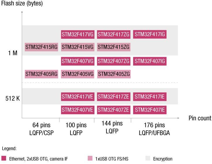
6 STM32 F4 portfolio 2

7 STM32 F4 block diagram Feature highlight 168 MHz Cortex-M4 CPU Floating point unit (FPU) ART Accelerator TM Multi-level AHB bus matrix 1-Mbyte Flash, 192-Kbyte SRAM 1.7 to 3.6 V supply RTC: <1 µa typ, sub second accuracy 2x full duplex I²S 3x 12-bit ADC 0.41 µs/2.4 MSPS 168 MHz timers 2
8 8 Content Product family overview F1/F2/F4 features comparisons Features highlight Boot & Remap feature RTC calibration & synchronization Reset & Regulator features I2S New Feature F1 to F2 to F4 porting guide


9 SRAM Comparison F4 Series F2 Series F1 Series Embedded SRAM 112K+64K+16K 112K+16K 64K Battery Backed-up SRAM 4K Bytes Not available 9
10 Flash Comparison F4 Series F2 Series F1 Series Embedded Flash (in Bytes) 512K, 1M 128K, 256K, 512K, 768K, 1M 16K, 32K, 64K, 128K, 256K, 384K, 512K, 768K, 1M User Flash sectors/ page sizes (in Bytes) 4*16K + 1*64K + 7*128K (sectors) 1K/page or 2K/page Depending on part number System Flash (Bytes) 30K 2K/6K/18K Option Bytes (Bytes) OTP area (Bytes) 528 Not available Prefetch 2*128bits 2*64bits Read interface Write interface Cache Instructions + data branch caches Not available Nb of Waitstates Depends on HCLK & Voltage range Depends only on HCLK Erase Mass erase or Sector erase Mass erase or Page erase Program 8bits / 16bits / 32bits / 64bits 16bits Vpp Provided externally (8V~9V ) Not available 10
11 Power supply architecture F4 Series F2 Series F1 Series Vdd Voltage Range 1.8V(1.7V) ~ 3.6V 1.8V(1.65V) ~ 3.6V 2.0V ~ 3.6V Vbat Voltage Range 1.65V ~ 3.6V 1.65V ~ 3.6V 1.8V ~ 3.6V Vdda ADC operational 1Msps 1.8V(1.7V)~3.6V 1Msps 1.8V(1.65V)~3.6V 2.4V ~ 3.6V Range ADC not operational 2Msps 2.4V~3.6V 2Msps 2.4V~3.6V 2.0V ~ 3.6V Running mode Available Available Power modes Sleep mode Available Available Standby mode Available Available Bypass mode Available Not Available Low power mode voltage regulator To power the SRAM when in low power mode Not Available Core voltage 1.2V 1.8V Additional power pin V cap1/2 To external provide 1.2V for the core Not Available V pp 7V - 9V Not Available 11
12 Clock schemes comparison F4 Series F2 Series F1 Series HSE Frequency Range 4~26MHz ( Bypass mode :1-26Mhz ) 4~16MHz & 3~25MHz LSE Frequency kHz kHz HSI typical freq. 16MHz 8MHz HSI typical freq. 32kHz 40kHz AHB/APB1/APB2 Maximum frequencies AHB : 168MHz APB1 : 42MHz APB2 : 84Mhz AHB : 120MHz APB1: 30MHz APB2 : 60MHz AHB : 72MHz APB1 : 36MHz APB2 : 72MHz PLL Dual PLL:PLL1 system clock and 48MHz clock PLL2 (for I2S audio) 1 or 3 PLLs MCO output MCO1 (PA.8) or MCO2 (PC.9) MCO (PA.8) Calibration Available via Timer5 Ch4 & Timer 11 ch1 Available via Timer5 Ch4 & Timer 11 ch1 Available via timer5 channel4 13
13 GPIO Features comparison F4 Series F2 Series F1 Series Operating modes Support 8/16/32Bits access BSRR[32] Supports only 32bits Access BSRR/BRR[32] Configuration Locking Available Available Available I/O Bandwidth 2/25/50/100/200MHz 2/25/50/100MHz 2/10/50 MHz Max toggling frequency 84MHz (AHB) 60MHz (AHB) 18MHz (APB2) Remap feature Switch selection Alternate function selectable pin by pin Available, each I/O has a internal switch to select the feature to connect to it. Group remapping Not available group remapping 14
14 ADC Features comparison F4 Series F2 Series F1 Series ADC1 Channels Channels 0~18 Channels 0~17 Conversion time (Sampling + conversion) Sampling time + 12/10/8/6 cycles for conversion time Sampling time cycles Max. ADC clock 36MHz * 30/15MHz * 14MHz ADC Trigger Raising or falling edge Raising edge Precision 12bits / 10 bits / 8bits / 6bits 12bits Precision Vs Speed Precision reduction to speed up conversion Not available Vbatt test Vbat/2 internally connected on Channel 18 Not available ADC Master/ Slave ADC1 Master ADC2 & ADC3 Slaves ADC1 Master /ADC2 Slave ADC3 standalone *Please refer to the datasheet for the ADC voltage range 15
15 F4 and F2 Improved ADC performances Total conversion time = T sample + T conversion Allow compromise between precision & conversion time Example : T sample =3 ADC cycles (smallest) For a ADC clock frequency of 30MHz Precision Conversion time Total conversion time 12 Bits 12 ADC clock cycles 12+3=15 cycles 0.5us 2Mbps 10 Bits 10 ADC clock cycles 10+3=13 cycles 0.433us 2.30Mbps 8 Bits 8 ADC clock cycles 8+3=11 cycles 0.366us 2.72Mbps 6 Bits 6 ADC clock cycles 6+3=9 cycles 0.3us 3.33Mbps These performances can be further improved (3x) by using the interleaved modes of the STM32 s ADC 16
16 RTC Features comparison F4 Series F2 Series F1 Series Calendar type Hardware D/M/Y + sub second register Hardware D/M/Y 32bits counter Alarm wakeup 16bits counter Not Available Calibration 50/60Hz high precision calibration input Not available Interrupts/ Wake up event Periodical wakeup / alarm/ tamper /timestamp Second/alarm/ overflow/ tamper Alarms AlarmA AlarmB AlarmA Backup registers 20 registers = 80Bytes 20 Bytes / 84 Bytes GPIO output Calibration/alarm/wakeup Calibration/alarm/se cond GPIO Input Tamper / timestamp Tamper input Protection after reset Unlock sequence available on all devices (not exactly the same between the devices) 17
17 DMA Features comparison F4 Series F2 Series F1 Series DMA Channels = = 12 DMA Requests DMA Request selected explicitly by a register ORED => Conflicts FIFO Each Channel as 4*32bits FIFO Not available Burst Mode Available Not available Software Trigger Channel priorities Peripheral flow control Available Software + Hardware priorities Available for the SDIO peripheral Available Software + Hardware priorities Not Available Interrupt flags 5 (DMA FIFO error/direct transfer error) 3 18
 allows")
18 USART Feature comparison F4 Series F2 Series F1 Series Oversampling Selectable : 8bits /16bits Fixed 16bits Max baudrate 84MHz / 8 = 10.5Mbps 60MHz / 8 = 7.5Mbps 72MHz / 16 = 4.5Mbps Sample point Selectable : 1 sample point or 3 sample points Fixed 3 sample points USART6 Available Not Available Note : reducing the number of sampling point (in noisefree environment) allows to increase the clock deviation tolerance Example : oversampling = 16bits,3 sampled points 19
19 SPI Features Max clock frequency F4 Series F2 Series F1 Series 37.5MHz 30MHz 18MHz TI Mode support Available Available Not available 8/16 位 20
20 Timer Features F4 Series F2 Series F1 Series Advanced timers TIM1/8 16bits up/down counter; 4 Channels IC/OC/PWM ; Complementary output & dead-time insertion (motor control) Standard timers TIM2~5 TIM3/4 : 16bits up/down counter TIM2/5 : 32bits up/down counter 4 Channels IC/OC/PWM 16bits up/down counter 4Channels IC/OC/PWM Basic timers TIM6/7 Standard timers TIM9/12 Standard timers 10/11/13/14 16Bits up/down counter;can be used as DAC trigger timers 16Bits up/down counter;2 Channels IC/OC/PWM 16Bits up/down counter;1 Channel IC/OC/PWM 21
21 Other features NVIC and EXTI F4 Series F2 Series F1 Series Maskable interrupts External interrupt/ wake up event 87 23,(including new event 3) High-speed OTG Mode wake up / RTC Wake up/rtc 60/68 20 F2 & F4 compared to F1 (other differences) : SDIO 48MHz clocked from PLL2 (F1 from AHB Clock) DAC operational on full voltage range (F1 2.4V) IWDG source clock 32kHz (F1Series =40kHz) reduced frequency = longer maximum watchdog timing 22
22 23 Content Product family overview F1/F2/F4 features comparisons Features highlight Boot & Remap feature RTC calibration & synchronization Reset & Regulator features I2S New Feature F1 to F2 to F4 porting guide
23 24 The STM32 Buses I-Bus : Instruction fetch in the address range 0x to 0x1FFFFFFF D-Bus : Data access in the address range 0x to 0x1FFFFFFF Best execution in Harvard architecture (when code is fetched from the I-Bus) S-Bus : Instruction fetch, Data access, peripheral access in the other address range

24 25 What is the FSMC remap feature FSMC is connected on the I-bus for faster code execution FSMC is also connected on the D-bus for faster data access FSMC is connected on the S bus This is the only configuration on STM32F1 This is the default configuration on STM32F2/F4 On STM32F2 this S-bus link is disconnected when I-Bus/D-Bus access is enabled On STM32F4 this S-bus link is always available even when I-Bus/D-Bus access is enable


25 26 The remap feature BOOT and SW Remap SW Remap only
26 27 The STM32F2xx Boot feature The boot part is similar to the STM32F1xx It is not possible to boot from the FSMC A software remap feature has been added IMPORTANT : The BOOT0/1 Marking on the MB786 Rev.A is inverted (the switch written as boot0 is indeed the boot1)
27 28 The remap register : SYSCFG_MEMRMP After reset the register takes the value of the boot pins (except if Boot0=0 and Boot1=1) Boot from the FSMC is not possible, so after reset If Boot0=0 and Boot1=1 the device starts from the main flash and the reset value of this register is 0b00 The FSMC remap (0b10) can only be enabled by software

.")
28 29 Example 1 : boot0=0, Boot1=0 The main flash is remapped at address 0x The MCU boots from the main flash The SYSCFG_MEMRMP register reset value is 0x The vector table is at its default address 0x Notes : in this configuration the main flash is accessible from both address ranges : 0x and 0x It is recommended to keep the code in the non-remapped main flash address range (0x ). This will avoid the code to be remapped unexpectedly to other areas by software


29 30 Example 2 : boot0=1, Boot1=0 The system memory is remapped at address 0x The MCU boots from the system memory The SYSCFG_MEMRMP register reset value is 0x The vector table is at its default address 0x

, the firmware will have to configure the FSMC and then write 0x2 in the SYSCFG_MEMRMP (see next slide for")
30 31 Example 3 : boot0=0, Boot1=1 The main flash is remapped at address 0x The MCU boots from the main flash The SYSCFG_MEMRMP register reset value is 0x The vector table is at its default address 0x NO BOOT Important Notes : In this configuration, the boot from main flash is enforced by the hardware (SYSCFG_MEMRMP is initialized to 0x ) For the remap the FSMC to be effective (right column), the firmware will have to configure the FSMC and then write 0x2 in the SYSCFG_MEMRMP (see next slide for complete sequence)
31 32 FSMC Remap Sequence 1. Configure Boot0/1 to boot from the main flash 2. Run the application code from the address 0x ( nonremapped main flash) 3. Remap the Vector Table to the non-remapped main flash area 0x Enable the SYSCFG Clock 5. Remap the FSMC by writing 0x2 into the SYSCFG_MEMRMP register Notes : This sequence does not maximize the security, to further secure it additional configuration is required (use of priviledges, MPU ) After Remap, the original FSMC address range (0x x9FFFFFFFF) is still accessible (STM32F4xx). After Remap, the first 2 blocks of the Bank1 are also accessible in the remapped area (bank1 block1 : 0x x03FFFFFF and bank1 block2 : 0x x07FFFFFF
32 33 Content Product family overview F1/F2/F4 features comparisons Features highlight Boot & Remap feature RTC calibration & synchronization Reset & Regulator features I2S New Feature F1 to F2 to F4 porting guide
33 34 STM32F2 Vs F4 : RTC differences Calendar STM32 F2 12/24 format Hour / Min / seconds STM32 F4 12/24 format Hour / Min / seconds / Subsecond Max resolution : 30.52µs (clk = 32768Hz) Shadow register bypass No Yes synchronization No Yes - On the fly synchronization Calibration type Coarse calibration Coarse & Smooth calibration Calibration windows 64 minutes 8s / 16s / 32s (On the fly) Calendar Calibration steps Alarm on calendar Time stamp Tamper detection Negative:-2ppm Positive: +4ppm 2 x alarms Sec, Min, Hour, Date/day Sec, Min, Hour, Date/day YES (2 pins /1 event) Edge Detection only Smooth calib. Negative or Positive: 3.81ppm / 1.91ppm / 0.95 ppm 2 x alarms : Sec, Min, Hour, Date/day, Sub seconds Sec, Min, Hour, Date/day, Sub seconds YES (2 pins / 2 events) Edge detection or Level Detection (with filtering)

34 35 Subsecond counter The Date/Time is updated with the 1Hz clock coming out of the synchronous prescaler The sub-second field is the value of the synchronous prescaler s counter. This field is not writable. Therefore the precision of the sub second counter depends on the PREDIV_S value (see next slide)
35 36 Subsecond counter Prediv_A SS Clock Prediv_S Sub second counter PREDIV_S high PREDIV_A low to get 1Hz Higher current consumption Higher input frequency (SS Clock) higher sub second precision (best precision is µs if SS Clock=32768 Hz) PREDIV_S low PREDIV_A high to get 1Hz Lower current consumption Lower input frequency (SS Clock) Lower sub second precision

36 37 F2 & F4 RTC Clock calibration F2 calibration coarse calibration after the prescaler Resolution : 4ppm Range 63 ppm to 126 ppm: F4 calibration Coarse calibration after the asynchronous prescaler Resolution : 4ppm Range 63 ppm to 126 ppm: smooth calibration on the fly before the asynchronous prescaler Resolution : ppm to ppm Range : -511 to +512 RTCCLK Note : On the STM32F4, the two calibration methods are not intended to be used together, the application must select one of the two methods. Coarse calibration is provided for compatibly reasons.
37 39 The coarse calibration (F2 & F4) The 512Hz clock output is before the calibration Cannot check its effect The 1Hz clock output is after the synchronous prescaler allows to check it Available on the STM32F4 only The calibration setting can only be changed during initialization Cannot be updated on the fly Suitable for static compensation Not suitable for temperature compensation The coarse calibration cannot be used together with the smooth calibration STM32F2 STM32F4
38 40 The smooth calibration (F4 Only) The smooth calibration is available : On the STM32F1 devices On the STM32F4 devices Both the 512Hz clock and 1Hz clock outputs are after the calibration Both allows to check it The calibration setting Can be updated on the fly Suitable for static compensation Also suitable for temperature or other compensation The smooth calibration is more precise Precision (ppm) Smooth calibration Coarse calibration -2 and +4 The smooth coarse calibration cannot be used together with the coarse calibration Range (ppm) -244 ~ ~ ~ ~ +126
39 41 The synchronization This allows to synchronize the clock to a master clock without modifying the calibration. This is available : On the STM32F1 devices On the STM32F4 devices This mechanism allow to adjust the calendar by adding or removing a few fractions from its counter. The shift function has no impact on the RTC clock. Therefore its effect cannot be seen on the AFO_Calib output the shift operation is initiated by a write into the RTC_SHIFTR register (on the fly) This feature is not compatible with the reference clock detection
40 42 The reference clock calibration The RTC provides a reference clock input (RTC_50Hz pin) that can be used to compensate the imprecision of the calendar frequency (1 Hz). Features : The reference clock calibration and the coarse calibration can not be used together. The reference clock calibration and the synchronization can not be used together. The reference clock calibration is the best (ensures a high calibrated time) if the 50 Hz is always available. If the 50 Hz input is lost, the LSE can be used. The reference clock detection can not be used in Vbat mode. The reference clock calibration can only be used if you provide a precise 50 or 60 Hz input.
41 43 Content Product family overview F1/F2/F4 features comparisons Features highlight Boot & Remap feature RTC calibration & synchronization Reset & Regulator features I2S New Feature F1 to F2 to F4 porting guide

42 F4/F2 Reset & Power regulator features Power supply range 1.8(1.7)~3.6V Lowering the power supply may impact the performances of some peripherals. Refer to the datasheet. Option to disable the internal reset circuit (if disabled, and external reset circuit is required ) 44
43 45 Regulator-Reset : what is available on F2/F4? Regulator ON Internal Regulator Bypass Brown out reset off Voltage Scaling Reset ON Regulator OFF STM32F2 STM32F4 STM32F2 STM32F4 LQFP64 Always enabled LQFP64 Not available LQFP100 Always ON Available LQFP100 Not available LQFP144 Always ON Available LQFP144 Not available WLCS66 Available Available WLCS66 Available Available UFBGA176 Available Available UFBGA176 Available Available LQFP64 Not available LQFP64 Not available Reset OFF LQFP100 N/A Available LQFP100 Not available LQFP144 N/A Available LQFP144 Not available WLCS66 N/A Available WLCS66 Available Available UFBGA176 N/A Available UFBGA176 N/A Available
44 46 F2/F4 : Regulator-Reset : when to use what Reset ON Reset OFF Regulator ON Only one Vdd power supply No need for external reset device This is the default configuration Available on all F2/F4 packages Only one Vdd power supply Need external reset circuit To use when the MCU need to run with a Vdd lower than 1.8V Check datasheet for minimum Vdd Available on F4 only LQFP100/144 UFBGA176 packages Regulator OFF Need Vdd & 1.2V power supplies No need for external reset circuit To use an external regulator Available on F2/F4 on WLCS66 and UFBGA176 packages Need Vdd & 1.2V power supplies Need external reset circuit To use when the MCU need to run with a Vdd lower than 1.8V Check datasheet for minimum Vdd While allowing the customer to use their own external regulator Available on WLCS66 (F2/F4) and UFBGA176 (F4 only) packages
45 47 F4 : Regulator ON - Reset ON/OFF details Internal Regulator Bypass Brown out reset off Voltage Scaling Reset ON Regulator ON : low power modes and conditions to respect There are three low-power modes: MR is used in the nominal regulation mode (Run) LPR is used in the Stop modes Power-down is used in Standby mode: the regulator output is in high impedance: the kernel circuitry is powered down, inducing zero consumption (but the contents of the registers and SRAM are lost). Reset OFF There are three low-power modes: MR is used in the nominal regulation mode (Run) LPR is used in the Stop modes Power-down is used in Standby mode: the regulator output is in high impedance: the kernel circuitry is powered down, inducing zero consumption (but the contents of the registers and SRAM are lost). The following conditions must be respected: NRST pin should be controlled by an external reset controller to keep the device under reset when VDD is below 1.7 V
46 48 F4 : Regulator OFF - Reset ON/OFF details Internal Regulator Bypass Brown out reset off Voltage Scaling Reset ON Regulator OFF : conditions to respect This mode allows to power the device as soon as VDD reaches 1.7 V. An 1.2 V source is supplied through VCAP_1 and VCAP_2 pins, in addition to VDD The following conditions must be respected: VDD should always be higher than VCAP_1 and VCAP_2. If the time for VCAP_1 and VCAP_2 to reach 1.08 V is faster than the time for VDD to reach 1.7 V, then PA0 should be connected to the NRST pin. Otherwise, PA0 should be asserted low externally during POR until VDD reaches 1.7 V. PA0 cannot be used as a GPIO pin since it allows to reset the part of the 1.2 V logic which is not reset by the NRST pin, when the internal regulator is off. This mode allows to power the device as soon as VDD reaches 1.7 V. An 1.2 V source is supplied through VCAP_1 and VCAP_2 pins, in addition to VDD Reset OFF The following conditions must be respected: VDD should always be higher than VCAP_1 and VCAP_2. PA0 should be kept low to cover both conditions: until VCAP_1 and VCAP_2 reach 1.08 V and until VDD reaches 1.7 V. NRST should be controlled by an external reset controller to keep the device under reset when VDD is below 1.7 V
47 51 Content Product family overview F1/F2/F4 features comparisons Features highlight Boot & Remap feature RTC calibration & synchronization Reset & Regulator features I2S New Feature F1 to F2 to F4 porting guide
48 I2S Half duplex Vs Full duplex STM32F2 I 2 S I 2 S SCK WS SD Out Half duplex (config. OUT) SCK WS SD In Half duplex (config. IN) STM32F4 I 2 S SCK WS SD out SD in Full duplex (IN & OUT) STM32F2 : 2xI 2 S Half duplex STM32F4 : 2xI 2 S Full duplex
49 53 Content Product family overview F1/F2/F4 features comparisons Features highlight Boot & Remap feature RTC calibration & synchronization Reset & Regulator features I2S New Feature F1 to F2 to F4 porting guide
50 54 IDE support for STM32F4 IDE versions natively supporting the STM32F4 - IAR 6.30 (see the release note) - Keil Version 4.22a - Atollic version 2.2 (2.3 preferred) -
51 About the pin to pin compatibility The devices are functional pin-to-pin compatible There are minor differences on the power supply pins QFP64 QFP100 QFP144 F1 QFP64 QFP100 QFP144 F2 & F PD0 - OSC_IN PH0 - OSC_IN PD1 - OSC_OUT VSSA VDD PH1 - OSC_OUT VREF VSSA VSS_ VCAP NC VCAP VSS_ VSS VSS_3 63 VSS_ VDD_SA 55
52 About the pin to pin compatibility STM32F4 and STM32F2 are hardware pin to pin compatible. Just pay attention to the F2 RFU pin software compatible STM32F4 and STM32F2 work with the same IDE STM32F1 and STM32F4 are Functional pin to pin compatible But not fully pin to pin compatible for the power supply part Compatible designs are detailed in the next slides. 56

53 LQFP144 STM32F1 compatible design Connected to Vss for the F1 series Connected to Vdd for F2 and F4 series Solder a 0ohm resistor for F1 series Keep it open for F2 and F4 series 57
54 LQFP100 STM32F1 compatible design Connected to Vss for the F1 series Connected to Vdd for F2 and F4 series Solder a 0ohm resistor for F1 series Keep it open for F2 and F4 series 58

55 LQFP64 STM32F1 compatible design Solder a 0ohm resistor for F1 series Keep it open for F2 and F4 series 59

56 Thanks - 谢谢!
Hello, and welcome to this presentation of the STM32L4 power controller. The STM32L4 s power management functions and all power modes will also be
 Hello, and welcome to this presentation of the STM32L4 power controller. The STM32L4 s power management functions and all power modes will also be covered in this presentation. 1 Please note that this
STM bit ARM Cortex MCUs STM32F030 Series
 STM32 32-bit ARM Cortex MCUs STM32F030 Series ST has licensed Cortex-M processors 2 Forget traditional 8/16/32-bit classifications and get Seamless architecture across all applications Every product optimized
Hello, and welcome to this presentation of the STM32 Real- Time Clock. It covers the main features of this peripheral, which is used to provide a
 Hello, and welcome to this presentation of the STM32 Real- Time Clock. It covers the main features of this peripheral, which is used to provide a very accurate time base. 1 The RTC peripheral features
Designing with STM32F2x & STM32F4
 Designing with STM32F2x & STM32F4 Course Description Designing with STM32F2x & STM32F4 is a 3 days ST official course. The course provides all necessary theoretical and practical know-how for start developing
AVR XMEGA Product Line Introduction AVR XMEGA TM. Product Introduction.
 AVR XMEGA TM Product Introduction 32-bit AVR UC3 AVR Flash Microcontrollers The highest performance AVR in the world 8/16-bit AVR XMEGA Peripheral Performance 8-bit megaavr The world s most successful
Hello, and welcome to this presentation of the STM32 Flash memory interface. It covers all the new features of the STM32F7 Flash memory.
 Hello, and welcome to this presentation of the STM32 Flash memory interface. It covers all the new features of the STM32F7 Flash memory. 1 STM32F7 microcontrollers embed up to 2 Mbytes of Flash memory.
AN4749 Application note
 Application note Managing low-power consumption on STM32F7 Series microcontrollers Introduction The STM32F7 Series microcontrollers embed a smart architecture taking advantage of the ST s ART- accelerator
Interconnects, Memory, GPIO
 Interconnects, Memory, GPIO Dr. Francesco Conti f.conti@unibo.it Slide contributions adapted from STMicroelectronics and from Dr. Michele Magno, others Processor vs. MCU Pipeline Harvard architecture Separate
STM32L4 System operating modes
 STM32L4 System operating modes Typical application profile 2 Tperiod Tperiod I DD Process IRQ ACTIVE IRQ ACTIVE OFF STARTUP INITIALIZATION TASKS Tasks TASKS INACTIVE INACTIVE INACTIVE Application phases:
STM32 F-2 series High-performance Cortex-M3 MCUs
 STM32 F-2 series High-performance Cortex-M3 MCUs STMicroelectronics 32 bit microcontrollers, 120 MHz/150 DMIPS with ART Accelerator TM and advanced peripherals www.st.com/stm32 STM32 F-2 series The STM32
Hello, and welcome to this presentation of the STM32 Reset and Clock Controller.
 Hello, and welcome to this presentation of the STM32 Reset and Clock Controller. 1 The RCC controller integrated inside STM32 products manages system and peripheral clocks. STM32F7 devices embed two internal
STM32F4 Labs. T.O.M.A.S Technically Oriented Microcontroller Application Services V1.07
 STM32F4 Labs T.O.M.A.S Technically Oriented Microcontroller Application Services V1.07 CONTENT 1/3 2 1. GPIO lab 2. EXTI lab 3. SLEEP lab 4. STOP lab 5. STANDBY lab 6. DMA Poll lab 7. DMA Interrupt lab
Advanced Microcontrollers Grzegorz Budzyń Extras: STM32F4Discovery
 Advanced Microcontrollers Grzegorz Budzyń Extras: STM32F4Discovery Plan STM32F4Discovery module STM32F407 description STM32F4Discovery STM32F4Discovery Easily availble(farnell), cheap(~15 EUR) and powerful
STM32F429 Overview. Steve Miller STMicroelectronics, MMS Applications Team October 26 th 2015
 STM32F429 Overview Steve Miller STMicroelectronics, MMS Applications Team October 26 th 2015 Today - STM32 portfolio positioning 2 More than 30 product lines High-performance 398 CoreMark 120 MHz 150 DMIPS
Introducing STM32 L0x Series. April
 Introducing STM32 L0x Series April 2014 www.emcu.it 20- to 80pins 20- to 100pins 48- to 144pins Memory size (Bytes) ST s Ultra-low-power Continuum (1/2) 2 512K 256K 192K STM32L0 Cortex TM -M0+ STM32L1
AVR XMEGA TM. A New Reference for 8/16-bit Microcontrollers. Ingar Fredriksen AVR Product Marketing Director
 AVR XMEGA TM A New Reference for 8/16-bit Microcontrollers Ingar Fredriksen AVR Product Marketing Director Kristian Saether AVR Product Marketing Manager Atmel AVR Success Through Innovation First Flash
STM8L and STM32 L1 series. Ultra-low-power platform
 STM8L and STM32 L1 series Ultra-low-power platform 8-bit and 32-bit MCU families 2 Flash (bytes) 2 M 1 M 128 K 16 K 8-bit Core STM8S Mainstream STM8A F and STM8AL Automotive STM8L Ultra-low-power 32-bit
STM32 F2 series High performance Cortex M3 MCUs
 STM32 F2 series High performance Cortex M3 MCUs STMicroelectronics 32 bit microcontrollers, 120 MHz/150 DMIPS with ART Accelerator TM and advanced peripherals www.st.com/stm32 STM32 F2 series The STM32
STM32F7 series ARM Cortex -M7 powered Releasing your creativity
 STM32F7 series ARM Cortex -M7 powered Releasing your creativity STM32 high performance Very high performance 32-bit MCU with DSP and FPU The STM32F7 with its ARM Cortex -M7 core is the smartest MCU and
STG - STM32 + FreeRTOS + LwIP/EmWin
 Formation STM32 + FreeRTOS + LwIP/EmWin: This course covers the STM32 ARM-based MCU family, the FreeRTOS Real Time OS, the LWIP TCP/IP Stack and/or the EmWin GUI Stack - Processeurs ARM: ST processors
 STM32 F4 Series Cortex M4 http://www.emcu.it/stm32f4xx/stm32f4xx.html www.emcu.it STM32 F4 Main common features Cortex -M4 (DSP + FPU) STM32F429/439 180 MHz 1 to 2-MB Flash 256-KB SRAM STM32F427/437 180
ARM Cortex core microcontrollers 12 th Energy efficient operation
 ARM Cortex core microcontrollers 12 th Energy efficient operation Balázs Scherer Budapest University of Technology and Economics Department of Measurement and Information Systems BME-MIT 2017 The importance
Universität Dortmund. MCUs Low-Power Features
 MCUs Low-Power Features Why Low Power Is so Important for MCUs? Longer battery life Smaller products Simpler power supplies Less EMI simplifies PCB Permanent battery Reduced liability Power as a Design
Xynergy It really makes the difference!
 Xynergy It really makes the difference! STM32F217 meets XILINX Spartan-6 Why Xynergy? Very easy: There is a clear Synergy achieved by combining the last generation of the most popular ARM Cortex-M3 implementation
AN4809 Application note
 Application note Migrating between STM32L0 Series and STM32L4 Series / STM32L4+ Series microcontrollers Introduction For the designers of STM32 microcontroller applications, being able to easily replace
AN4325 Application note
 Application note Getting started with STM32F030xx and STM32F070xx series hardware development Introduction This application note is intended for system designers who require a hardware implementation overview
STM32G0 MCU Series Efficiency at its Best
 STM32G0 MCU Series Efficiency at its Best Key Messages of STM32G0 Series 2 2 3 Efficient Arm Cortex -M0+ at 64 MHz Compact cost: maximum I/Os count Best RAM/Flash Ratio Smallest possible package down to
STM32 F0 Value Line. Entry-level MCUs
 STM32 F0 Value Line Entry-level MCUs Key Messages 2 STM32 F0: Is the Cortex -M0 core generated with ST s STM32 DNA, for cost sensitive designs. The STM32 F0 is benefiting of STM32 DNA, providing the essential
AN4675 Application note
 Application note Migration of microcontroller applications from STM32F42xxx/STM32F43xxx to STM32F469xx/STM32F479xx Introduction For more and more applications using STM32 products, it is important to migrate
STM32L4+ MCU series Excellence in ultra-low-power with more performance
 STM32L4+ MCU series Excellence in ultra-low-power with more performance Key messages of STM32 L4+ series 2 + More performance and still ULP leader ST has stretched the STM32L4 architecture to reach 150
AK-STM32-ETH Development Board
 AK-STM32-ETH Development Board Reference manual Copyright 2011 Artekit Italy All rights reserved Contents About this document... 3 Revision history... 3 Contact information... 3 Life support policy...
The course provides all necessary theoretical and practical know-how for start developing platforms based on STM32L4 family.
 Designing with STM32L4 Family Course Description Designing with STM32L4 is a 3 days ST official course. The course provides all necessary theoretical and practical know-how for start developing platforms
Microcontrollers: Lecture 2 Low power Modes, Buses, Memory, GPIOs. Michele Magno
 Microcontrollers: Lecture 2 Low power Modes, Buses, Memory, GPIOs Michele Magno 1 Calendar 07.04.2016: Power consumption; Low power States; Buses, Memory, GPIOs 08.04.2016 Interrupts, Timers, ADC, DAC
STM32F7 series ARM Cortex -M7 powered Releasing your creativity
 STM32F7 series ARM Cortex -M7 powered Releasing your creativity STM32 high performance Very high performance 32-bit MCU with DSP and FPU The STM32F7 with its ARM Cortex -M7 core is the smartest MCU and
TEVATRON TECHNOLOGIES PVT. LTD Embedded! Robotics! IoT! VLSI Design! Projects! Technical Consultancy! Education! STEM! Software!
 Summer Training 2016 Advance Embedded Systems Fast track of AVR and detailed working on STM32 ARM Processor with RTOS- Real Time Operating Systems Covering 1. Hands on Topics and Sessions Covered in Summer
Arduino Uno R3 INTRODUCTION
 Arduino Uno R3 INTRODUCTION Arduino is used for building different types of electronic circuits easily using of both a physical programmable circuit board usually microcontroller and piece of code running
STM32G070CB/KB/RB. Arm Cortex -M0+ 32-bit MCU, 128 KB Flash, 36 KB RAM, 4x USART, timers, ADC, comm. I/Fs, V. Features
 STM32G070CB/KB/RB Arm Cortex -M0+ 32-bit MCU, 128 KB Flash, 36 KB RAM, 4x USART, timers, ADC, comm. I/Fs, 2.0-3.6V Datasheet - production data Features Core: Arm 32-bit Cortex -M0+ CPU, frequency up to
AN2585 Application note
 AN2585 Application note Application examples of the STM32F101xx and STM32F103xx core and system peripherals Introduction The STM32F10xxx is built around the latest Cortex -M3 core from ARM designed for
Hello, and welcome to this presentation of the STM32L4 System Configuration Controller.
 Hello, and welcome to this presentation of the STM32L4 System Configuration Controller. 1 Please note that this presentation has been written for STM32L47x/48x devices. The key differences with other devices
STM32 Cortex-M3 STM32F STM32L STM32W
 STM32 Cortex-M3 STM32F STM32L STM32W 01 01 STM32 Cortex-M3 introduction to family 1/2 STM32F combine high performance with first-class peripherals and lowpower, low-voltage operation. They offer the maximum
Reset and clock control (RCC)
") Reset and clock control (RCC) RESET Sources 86 System RESET Resets all registers except some RCC registers, PWR registers and Backup domain Sources Low level on the NRST pin (External Reset) WWDG event
Reset and clock control (RCC) RESET Sources 86 System RESET Resets all registers except some RCC registers, PWR registers and Backup domain Sources Low level on the NRST pin (External Reset) WWDG event
Value-line ARM -based 32-bit MCU with up to 256 KB Flash, timers, ADC, communication interfaces, V operation
 Features STM32F030x4 STM32F030x6 STM32F030x8 STM32F030xC Value-line ARM -based 32-bit MCU with up to 256 KB Flash, timers, ADC, communication interfaces, 2.4-3.6 V operation Datasheet - production data
M68HC08 Microcontroller The MC68HC908GP32. General Description. MCU Block Diagram CPU08 1
 M68HC08 Microcontroller The MC68HC908GP32 Babak Kia Adjunct Professor Boston University College of Engineering Email: bkia -at- bu.edu ENG SC757 - Advanced Microprocessor Design General Description The
Design and development of embedded systems for the Internet of Things (IoT) Fabio Angeletti Fabrizio Gattuso
 Fabio Angeletti Fabrizio Gattuso") Design and development of embedded systems for the Internet of Things (IoT) Fabio Angeletti Fabrizio Gattuso Microcontroller It is essentially a small computer on a chip Like any computer, it has memory,
Design and development of embedded systems for the Internet of Things (IoT) Fabio Angeletti Fabrizio Gattuso Microcontroller It is essentially a small computer on a chip Like any computer, it has memory,
AN4809 Application note
 AN4809 Application note Migrating between STM32L0 Series and STM32L4 Series / STM32L4+ Series microcontrollers Introduction For the designers of STM32 microcontroller applications, being able to easily
Hello, and welcome to this presentation of the STM32 Low Power Universal Asynchronous Receiver/Transmitter interface. It covers the main features of
 Hello, and welcome to this presentation of the STM32 Low Power Universal Asynchronous Receiver/Transmitter interface. It covers the main features of this interface, which is widely used for serial communications.
LPC4370FET256. Features and benefits
 Page 1 of 5 LPC4370FET256 32-bit ARM Cortex-M4 + 2 x M0 MCU; 282 kb SRAM; Ethernet;two HS USBs; 80 Msps 12-bit ADC; configurable peripherals The LPC4370 are ARM Cortex-M4 based microcontrollers for embedded
STM32L0x Ultra Low Power - LCD - DMA - GPIO - RTC
 STM32L0x Ultra Low Power - LCD - DMA - GPIO - RTC MCD Application Team January-2014 V1.0 Analog Peripherals LCD GLASS CONTROLLER (LCD) Main features 3 High Flexibility Frame Rates Drive up to 320 (8x40)
Getting Started With the Stellaris EK-LM4F120XL LaunchPad Workshop. Version 1.05
 Getting Started With the Stellaris EK-LM4F120XL LaunchPad Workshop Version 1.05 Agenda Introduction to ARM Cortex Cortex -M4F M4F and Peripherals Code Composer Studio Introduction to StellarisWare, I iti
STM32x. tec.pres. STM32 ARM CortexTM-M3 Based Product Introduction
 STM32x tec.pres. STM32 ARM CortexTM-M3 Based Product Introduction 0101 STM32x Cortex M3 Hierarchical processor integrating core and advanced system peripherals Cortex-M3 core Harvard architecture 3-stage
STM32 Journal. In this Issue:
 Volume 1, Issue 2 In this Issue: Bringing 32-bit Performance to 8- and 16-bit Applications Developing High-Quality Audio for Consumer Electronics Applications Bringing Floating-Point Performance and Precision
STM32F401xB STM32F401xC
 STM32F401xB STM32F401xC ARM Cortex-M4 32b MCU+FPU, 105 DMIPS, 256KB Flash/64KB RAM, 10 TIMs, 1 ADC, 11 comm. interfaces Data brief 1 12-bit, 2.4 MSPS A/D converter: up to 16 channels WLCSP49 (3 x 3 mm)
STM8L151x6/8 STM8L152x6/8
 8-bit ultra-low-power MCU, up to 64 KB Flash, 2 KB data EEPROM, RTC, LCD, timers, USARTs, I2C, SPIs, ADC, DAC, comparators Features Datasheet - production data Operating conditions Operating power supply:
Product Technical Brief S3C2412 Rev 2.2, Apr. 2006
 Product Technical Brief S3C2412 Rev 2.2, Apr. 2006 Overview SAMSUNG's S3C2412 is a Derivative product of S3C2410A. S3C2412 is designed to provide hand-held devices and general applications with cost-effective,
Introduction to ARM LPC2148 Microcontroller
 Introduction to ARM LPC2148 Microcontroller Dr.R.Sundaramurthy Department of EIE Pondicherry Engineering College Features of LPC2148 in a Nut Shell CPU = ARM 7 Core Word Length = 32 Bit ROM = 512 KB RAM
ARM Cortex-M4 32b MCU+FPU, 225DMIPS, up to 2MB Flash/256+4KB RAM, USB OTG HS/FS, Ethernet, 17 TIMs, 3 ADCs, 20 comm. interfaces, camera & LCD-TFT
 STM32F429xx ARM Cortex-M4 32b MCU+FPU, 225DMIPS, up to 2MB Flash/256+4KB RAM, USB OTG HS/FS, Ethernet, 17 TIMs, 3 ADCs, 20 comm. interfaces, camera & LCD-TFT Data brief Features Core: ARM 32-bit Cortex
to ARM Cortex TM -M3 October 17, 2007 MCD Application Team
 Introduction to ARM Cortex TM -M3 October 17, 2007 MCD Application Team CONTENTS Introduction to the Cortex-M3 Architecture Overview Comparison to ARM7 Bit Banding and Unaligned data access Interrupt and
STM32SnippetsL0. STM32L0xx Snippets firmware package. Features. Description
 STM32L0xx Snippets firmware package Data brief Features Complete free C source code firmware examples for STM32L0xx microcontrollers Basic examples using direct-access registers as defined in CMSIS Cortex
Product Technical Brief S3C2413 Rev 2.2, Apr. 2006
 Product Technical Brief Rev 2.2, Apr. 2006 Overview SAMSUNG's is a Derivative product of S3C2410A. is designed to provide hand-held devices and general applications with cost-effective, low-power, and
Hello, and welcome to this presentation of the STM32 Universal Synchronous/Asynchronous Receiver/Transmitter Interface. It covers the main features
 Hello, and welcome to this presentation of the STM32 Universal Synchronous/Asynchronous Receiver/Transmitter Interface. It covers the main features of this USART interface, which is widely used for serial
For reference only Refer to the latest documents for details
 STM32F3 Technical Training For reference only Refer to the latest documents for details STM32F37x Specific Features/ peripherals Sigma delta analog to digital converter (SDADC) SDADC introduction (1/2)
AN4311 Application note
 Application note Assessing STM32L1 Series current consumption Introduction The STMicroelectronics ARM Cortex -M3 based STM32L1 series uses ST s proprietary ultra-low-leakage process technology with an
Hello, and welcome to this presentation of the STM32 general-purpose IO interface. It covers the general-purpose input and output interface and how
 Hello, and welcome to this presentation of the STM32 general-purpose IO interface. It covers the general-purpose input and output interface and how it allows connectivity to the environment around the
STM32L052x6 STM32L052x8
 Ultra-low-power 32-bit MCU ARM-based Cortex-M0+, up to 64 KB Flash, 8 KB SRAM, 2 KB EEPROM, USB, ADC Data brief Features Ultra-low-power platform 1.65 V to 3.6 V power supply -40 to 105/125 C temperature
MICROPROCESSOR BASED SYSTEM DESIGN
 MICROPROCESSOR BASED SYSTEM DESIGN Lecture 5 Xmega 128 B1: Architecture MUHAMMAD AMIR YOUSAF VON NEUMAN ARCHITECTURE CPU Memory Execution unit ALU Registers Both data and instructions at the same system
Embedded Programming with ARM Cortex-M3 Basic Experiments 1
 Embedded Programming with ARM Cortex-M3 Basic Experiments 1 Alan Xiao, Ph.D Handheld Scientific, Inc. qiwei@handheldsci.com Today s Topics Basics (with the Discovery board): 1. General Input/Output (GPIO)
STM32 MICROCONTROLLER
 STM32 MICROCONTROLLER Lecture 2 Prof. Yasser Mostafa Kadah Harvard and von Neumann Architectures Harvard Architecture a type of computer architecture where the instructions (program code) and data are
AN4936 Application note
 Application note Migration of microcontroller applications from STM32F7 Series to STM32H7x3 line microcontrollers Introduction Designers of STM32 microcontroller applications must be able to easily replace
New STM32WB Series MCU with Built-in BLE 5 and IEEE
 New STM32WB Series MCU with Built-in BLE 5 and IEEE 802.15.4 Make the Choice of STM32WB Series The 7 keys points to make the difference 2 Open 2.4 GHz radio Multi-protocol Dual-core / Full control Ultra-low-power
PC87435 Enhanced IPMI Baseboard Management Controller
 April 2003 Revision 1.01 PC87435 Enhanced IPMI Baseboard Management Controller General Description The PC87435 is a highlyintegrated Enhanced IPMI Baseboard Management Controller (BMC), or satellite management
AN3427 Application note
 Application note Migrating a microcontroller application from STM32F1 to STM32F2 series 1 Introduction For designers of STM32 microcontroller applications, it is important to be able to easily replace
Remote Keyless Entry In a Body Controller Unit Application
 38 Petr Cholasta Remote Keyless Entry In a Body Controller Unit Application Many of us know this situation. When we leave the car, with a single click of a remote control we lock and secure it until we
AN4088 Application note
 Application note Migrating from STM32F1 to STM32F0 Introduction For designers of STM32 microcontroller applications, it is important to be able to easily replace one microcontroller type by another one
AT-501 Cortex-A5 System On Module Product Brief
 AT-501 Cortex-A5 System On Module Product Brief 1. Scope The following document provides a brief description of the AT-501 System on Module (SOM) its features and ordering options. For more details please
AN5123 Application note
 Application note STSPIN32F0A - bootloader and USART protocol Introduction Cristiana Scaramel The STSPIN32F0A is a system-in-package providing an integrated solution suitable for driving three-phase BLDC
ARDUINO MEGA INTRODUCTION
 ARDUINO MEGA INTRODUCTION The Arduino MEGA 2560 is designed for projects that require more I/O llines, more sketch memory and more RAM. With 54 digital I/O pins, 16 analog inputs so it is suitable for
AN4515 Application note
 Application note Using Batch Acquisition Mode (BAM) to maximize power efficiency on STM32F410/411/412 microcontroller lines Introduction The STM32F410, STM32F411 and STM32F412 lines are part of the STM32
Engineer-to-Engineer Note
 Engineer-to-Engineer Note EE-388 Technical notes on using Analog Devices products and development tools Visit our Web resources http://www.analog.com/ee-notes and http://www.analog.com/processors or e-mail
Military Grade SmartFusion Customizable System-on-Chip (csoc)
") Military Grade SmartFusion Customizable System-on-Chip (csoc) Product Benefits 100% Military Temperature Tested and Qualified from 55 C to 125 C Not Susceptible to Neutron-Induced Configuration Loss Microcontroller
Military Grade SmartFusion Customizable System-on-Chip (csoc) Product Benefits 100% Military Temperature Tested and Qualified from 55 C to 125 C Not Susceptible to Neutron-Induced Configuration Loss Microcontroller
FiO Lite Datasheet FEATURES SAMPLE APPLICATIONS. FiO Lite
 FiO Lite Datasheet FEATURES Built-in RapidSTM native-support bootloader. ARM -bits Cortex TM M Processor (STMF0R) - 0MIPS maximum speed - 0 KBytes SRAM - 5 GPIO - channels -bit, µs ADC - USART, SPI, I
AN2606 Application note
 Application note STM32 microcontroller system memory boot mode Introduction The bootloader is stored in the internal boot ROM memory (system memory) of STM32 devices. It is programmed by ST during production.
Course Introduction. Purpose: Objectives: Content: Learning Time:
 Course Introduction Purpose: This course provides an overview of the Renesas SuperH series of 32-bit RISC processors, especially the microcontrollers in the SH-2 and SH-2A series Objectives: Learn the
AN Migrating to the LPC1700 series
 Rev. 01 6 October 2009 Application note Document information Info Keywords Abstract Content LPC1700, Migration, LPC2300/2400, ARM7, Cortex-M3 This application note introduces the important features of
EE 354 Fall 2015 Lecture 1 Architecture and Introduction
 EE 354 Fall 2015 Lecture 1 Architecture and Introduction Note: Much of these notes are taken from the book: The definitive Guide to ARM Cortex M3 and Cortex M4 Processors by Joseph Yiu, third edition,
Welcome to this presentation of the STM32 direct memory access controller (DMA). It covers the main features of this module, which is widely used to
. It covers the main features of this module, which is widely used to") Welcome to this presentation of the STM32 direct memory access controller (DMA). It covers the main features of this module, which is widely used to handle the STM32 peripheral data transfers. 1 The Direct
Welcome to this presentation of the STM32 direct memory access controller (DMA). It covers the main features of this module, which is widely used to handle the STM32 peripheral data transfers. 1 The Direct
ZigBee Compliant Platform 2.4G RF Low Power Transceiver Module for IEEE Standard. DATA SHEET Version B
 ZMD400-A01 ZigBee Compliant Platform 2.4G RF Low Power Transceiver Module for IEEE 802.15.4 Standard DATA SHEET Version B Quan International Co., Ltd., ZMD400 Features Fully compliant 802.15.4 Standard
AN3268 Application note
 Application note STM32VLDISCOVERY firmware package Introduction The purpose of this application note is to describe the STM32VLDISCOVERY package structure and provide short descriptions of: STM32VLDISCOVERY
Hello, and welcome to this presentation of the STM32F7 System Configuration Controller.
 Hello, and welcome to this presentation of the STM32F7 System Configuration Controller. 1 STM32F7 microcontrollers feature a set of configuration registers. The System Configuration Controller gives access
Table 1. Device summary STM32G081CB, STM32G081EB, STM32G081GB, STM32G081KB, STM32G081RB. Table 2. Device variants. Device marking (1) REV_ID (2)
 REV_ID (2)") Errata sheet STM32G081xB device errata Applicability This document applies to the part numbers of STM32G081xB devices and the device variants as stated in this page. It gives a summary and a description
Errata sheet STM32G081xB device errata Applicability This document applies to the part numbers of STM32G081xB devices and the device variants as stated in this page. It gives a summary and a description
AN4228 Application note
 Application note Migrating from STM32F1 Series to STM32F3 Series microcontrollers Introduction For the designers of STM32 microcontroller applications, being able to replace easily one microcontroller
New STM32 F7 Series. World s 1 st to market, ARM Cortex -M7 based 32-bit MCU
 New STM32 F7 Series World s 1 st to market, ARM Cortex -M7 based 32-bit MCU 7 Keys of STM32 F7 series 2 1 2 3 4 5 6 7 First. ST is first to sample a fully functional Cortex-M7 based 32-bit MCU : STM32
NXP Microcontrollers Selection Guide
 November 2012 NXP Microcontrollers Selection Guide NXP LPC family of microcontrollers is changing the landscape for embedded applications. Featuring award-winning innovations in connectivity, flexibility,
[MG2420] MCU Module Datasheet. (No. ADS0705) V1.0
![[MG2420] MCU Module Datasheet. (No. ADS0705) V1.0](/thumbs/78/77496075.jpg "[MG2420] MCU Module Datasheet. (No. ADS0705) V1.0") [MG2420] MCU Module Datasheet (No. ADS0705) V1.0 REVISION HISTORY Version Date Description VER.1.0 2013.10.22 First version release. V1.0 Page:2/17 CONTENTS 1. INTRODUCTION... 4 1.1. DEFINITIONS... 4 2.
[MG2420] MCU Module Datasheet (No. ADS0705) V1.0 REVISION HISTORY Version Date Description VER.1.0 2013.10.22 First version release. V1.0 Page:2/17 CONTENTS 1. INTRODUCTION... 4 1.1. DEFINITIONS... 4 2.
Product Technical Brief S3C2440X Series Rev 2.0, Oct. 2003
 Product Technical Brief S3C2440X Series Rev 2.0, Oct. 2003 S3C2440X is a derivative product of Samsung s S3C24XXX family of microprocessors for mobile communication market. The S3C2440X s main enhancement
PIC Microcontroller Introduction
 PIC Microcontroller Introduction The real name of this microcontroller is PICmicro (Peripheral Interface Controller), but it is better known as PIC. Its first ancestor was designed in 1975 by General Instruments.
STM32L151xx STM32L152xx
 STM32L151xx STM32L152xx Ultralow power ARM-based 32-bit MCU with up to 128 KB Flash, RTC, LCD, USB, USART, I2C, SPI, timers, ADC, DAC, comparators Data brief Features Operating conditions Operating power
ARM Cortex-M4 Architecture and Instruction Set 1: Architecture Overview
 ARM Cortex-M4 Architecture and Instruction Set 1: Architecture Overview M J Brockway January 25, 2016 UM10562 All information provided in this document is subject to legal disclaimers. NXP B.V. 2014. All
EFM32....the world s most energy friendly microcontrollers
 EFM32...the world s most energy friendly microcontrollers Energy Micro s Mission EFM32 Gecko Microcontrollers... the world s most energy friendly microcontrollers EFR Draco Radios... the world s most energy
2-Oct-13. the world s most energy friendly microcontrollers and radios
 1 2 3 EFM32 4 5 LESENSE Low Energy Sensor Interface Autonomous sensing in Deep Sleep LESENSE with central control logic ACMP for sensor input DAC for reference generation Measure up to 16 sensors Inductive
STM32F103xF STM32F103xG
 STM32F103xF STM32F103xG XL-density performance line ARM-based 32-bit MCU with 768 KB to 1 MB Flash, USB, CAN, 17 timers, 3 ADCs, 13 communication interfaces Data brief Features Core: ARM 32-bit Cortex