EnergyLogicIQ Gen User Manual & Installation Guide
|
|
|
- Martha McDowell
- 5 years ago
- Views:
Transcription


1 EnergyLogicIQ Gen User Manual & Installation Guide
2 Disclaimer: Logic Ladder Technologies makes no representations or warranties with respect to the contents or use of this manual, any software drivers or associated application software provided with this product and specifically disclaims any expressed or implied warranties of merchantability or fitness for any particular purpose. Logic Ladder Technologies reserves the right to modify or revise all or part of this document, its contents, and any products described herein at any time without prior notification and shall not be responsible for any loss, cost or damage, including consequential damage, caused by reliance on these materials. Logic Ladder Technical Support Contact Information: Phone: Online Support: Safety Notices: 1. Please read all instructions before installing and powering the unit. You should keep these instructions in a safe place for future reference. When installing and using this electrical equipment, always follow basic precautions. 2. If the power supply shows signs of damage or malfunction, stop using it immediately, turn off the power and disconnect the power supply before contacting your supplier for a repair or replacement. 3. Changes or modifications not expressly approved by the party responsible for compliance could void the user s authority to operate the equipment. Use only the accessories, attachments, and power supplies provided by the manufacturer
3 connecting non-approved antennas or power supplies may damage the unit, cause interference or create an electric shock hazard, and will void the warranty. 4. Do not attempt to repair the product. The unit contains no electronic components that can be serviced or replaced by the user. Any attempt to service or repairr the unit by the user will void the product warranty. 5. Ports that are capable of connecting to other apparatus are defined as SELV ports. To ensure conformity with IEC60950 ensure that these ports are only connected to ports of the same type on other apparatus. NOTE: A licensed electrician may be required to install or perform maintenance on this equipment. Always follow applicable local, state and federal codes and guidelines. DANGER! - RISK OF ELECTRICC SHOCK: Always disconnect the mains AC voltage prior to any work on this equipment. WARNING! - An appropriate external disconnect device must be installed and properly marked to ensure that an electrical hazard is not present. WARNING! - Bonding between conduit and Protected Earth (PE) is required and must be part of the installation. WARNING! - Conduit hub. WARNING! - Mounting the device in a correct orientation will ensure proper orientation. Please verify the correct orientation as indicated on the device. Cover screws are required as part of the safety rating. Product Disposal Instructions This product contains high quality materials and components which can be recycled. At the end of its life cycle this product MUST NOT be mixed with other commercial waste for disposal. Check with the terms and conditions of your supplier for disposal information.
4 TABLE OF CONTENTS 1. Getting started 2. Package Content 3. EnergyLogicIQ Gen Components 3.1 Hardware 3.2 Fuel Sensor Operating Principle Mechanical Specifications Electrical Specifications Measurement Specifications Wiring Connectionn Calibration Sensor Drawings Installation Procedure 3.3. EnergyLogicIQ Gateway Comprehensive IOs Cellular features 3.4. Energy Meter Features Wiring Diagrams Technical Specification Operation Details Programmingg Mode Run Mode 3.5. Mountings 3.6. Troubleshooting 3.7. Installation Scenario
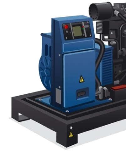
5 1. Getting Started: EnergyLogicIQ-Generator provides remote generator monitoring. It helps you to monitor the generators from a remote control and command centre. The equipment contains hardware components that have been manufactured by various LogicLadder vendors; they are reputed manufacturers in their receptive fields which leads LogicLadder to provide custom solution in plug and play fashion. 2. Package Contents: EnergyLogicIQ-Generator packaging consists of following: 1) EnergyLogicIQ-Gen 2) Instruction Manual 3. EnergyLogicIQ-Generator Components EnergyLogicIQ-Generator consists of following components: 3.1 Hardware: 1) Capacitive Fuel Sensor 2) RTU (EnergyLogicIQ Gen Std with daughter board.) 3) Energy Meter 3.2) Fuel Sensor: Fuel sensor is used to monitor the fuel level present in the diesel generator tank. By precisely measuring the level of diesel we compute diesel volume present in tank considering the area of diesel tank ) Operating Principle:

 *hx / ln (r2/r1) 3.2.2) Mechanical Specifications: S.No.")
6 Capacitance liquid level sensor use capacitance principle to measuree the dielectric permittivity of a surrounding medium. Fuel sensor use capacitance principle to measure the dielectric permittivity of a surrounding medium. Capacitance value linearly changed when liquid level up and down. With the advantage of high accuracy, high stability and continuous working ability, capacitance liquid level sensor is widely used in industrial manufacturer. Where C0 - is constant capacitance - is Liquid dielectric constant ε0 - air dielectric constant hx - liquid level CC=C0+ΔC= C0+ K (εr-ε0) *hx / ln (r2/r1) 3.2.2) Mechanical Specifications: S.No. Parameter Details Housing Aluminum or stainless steel weather & flame proof suitable 1 for mounting in hazardous area gas group IIA & IIB as per IS Mounting Integral with sense rod or probe with SS / MS(plated)
7 3 Cable entry and gland Screw - 1"/1-1/2" BSP/NPT (M) Flanged integrated with sensor rod Specially designed hook type connector,3 threaded wires for connection to the DAQ 5 Sensing Sensors effective Zone 6 Stilling tube Pipe, GI / SS 7 Overall dimensions Electrical Specifications: S. No. Parameter Please refer enclosed probe drawing 1 Power Supply 15-28VDC,Typical Power 24VDC 2 Output signal 4-20mA Measurement Specifications: Details S. No. Parameter 1 Measuring Range 2 Response Time 3 Accuracy 4 Electronics Ambient Temp. 5 Working Pressure 6 Repetitive Error Details mm(user selectable) 0.5 to 5 seconds ± 1 % FS or better * -40 C to +85 C 0.63MPa <±0.02%F.S Wiring Connection: Cable Color Project Definition RED +24VDC Power Supply typical BLACK Ground Power Supply Ground BLUE IOUT Current output(4-20ma)


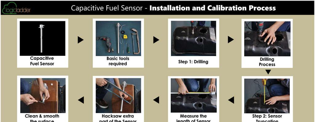
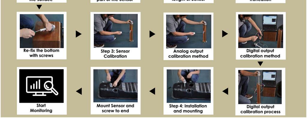
8 6. Calibration: We need to calibrate the sensor at any two levels before taking any reading from it. Calibrating the sensor we need the handheld calibrator connected with the sensor output connector Slide switch on the right side, placed ON, the POWER light Adjust the liquid levell to the zero position, and then press EMPTY button for nearly 2 seconds until the SET light shines one time, mean zero calibration and confirms the zero calibration of the sensor To adjust the liquid level to the full position/high, then press FULL button for nearly 2 seconds until the SET light shines one time, mean full calibration success After the calibration process release the calibration device connector, then follow the wiring method Both the calibration processes must be completed together, if the calibration output is abnormal, please follow the above steps to calibrate once again

9 Sensor Drawings Front View Top View Installation Procedure Sensor Installation Steps A. Basic tools required: driver etc. Drill machine, measuring tape, cutter (Hexa blade), screw B. Drilling First, clean the tank residual oil, and then rinse it with clean water many times to make it look best. While selecting the drilling point on the center of the oil tank surface please consider the point that it should not conflict with the inside tank unit. Use hole saw to drill point on the selected fixed point, when drilling, please avoid the iron filing by falling into the tank.
10 When completed, according to sensor gasket holes, select smaller drills for the process of fixing holes. C. Sensor Truncation First, measure inside height of the tank, to get the value H. The inside height of the tank H - 10mm = L (L is the sensor height from flange lower end portion to the bottom). Post getting the value L, use a hacksaw to saw off the excess part of the sensor. After sawing off, use grater to clean the surface fine, maintain the surface smooth and clean. Clean the interior and exterior aluminum scrap. Once the bottom is fixed to the terminal with screws, now the sawing off is over. When the sensor is truncated, you must re-calibrate sensor to fuel tank capacity. After fixing the sensor on the diesel tank your installation is over EnergyLogicIQ Gen EnergyLogicIQ Gen is powerful ARM based Cloud connector gateway which uses telit module for GSM communication. Intelligent logic built inside the hardware provides the Firmware update Over-The-Air (FOTA) and Configuration Over-The-Air (COTA) features. EnergyLogicIQ Gen has multiple communication modes like HTTP, TCP/IP and communicate cloud server on GPRS. Watchdog timer is inbuilt for power reset and hardware failures Comprehensive IOs 4 Digital Inputs - monitoring the ON/OFF status of generator. 4 Digital Outputs - controlling of relay and switches and online controlling of Generator.
11 4 ADC Inputs - monitoring the fuel Levels in the generator tanks and Battery Voltages of Generator. 2 Serial Ports - RS485/RS232, serial port for connecting of smart Energy meters for electricity produced by generators. 1 CAN Interface - Enhancing feature to inbuilt further controller network Cellular features Supports Quad band frequencies : 850/900/1800/1900MHz High gain antenna for better connectivity, specifically used for rural areas Energy Meter Features: All parameters with default accuracy class 1.0S Measurement of all important Electrical Parameters Display with customized LCD Individual voltages and currents for all three phases (R-Y-B) Individual powers and system powers (KW, KVA and KVAR) Individual PF and system PF with lead (-) and lag side Frequency (Hz), three energies (KWh, KVAh, KVARh)
12 Wiring Diagrams: Fig# Connection diagram
13 Fig# Connection Scheme For installation and commissioning of 3P4W, follow the below mentioned instructions: Push the unit into the panel and mount using the claim provided on it. Connect the auxiliary supply (80V AC to 270V AC) to the terminals marked P and N. Connect the three phases with the phase sequence being R-Y-B to the terminals marked U1, U2 and U3 respectively. Make sure that the phasess coming to the unit come through control fuses of 1.0A rating. This will protectt the electronic inside from damage due to severe over voltage or phase faults in the system. Connect the neutral wire to the terminal marked U4. Connect the two wires from the R-phase CT to the terminal marked M1 and L1 such that S1 from CT goes to M1. Connect the two wires from the Y-phase CT to the terminals marked M2 and L2 such that S1 from the CT goes to M2.
14 Connect the two wires from the B-phase CT to the terminals marked M3 and L3 such that S1 from the CT goes to the terminal marked M3. Switch on the auxiliary supply as well as three phase supply and then, the unit will come alive in order to display such as TRINITY ESPL, CT RATIO, and Run mode respectively. The user should program the settable parameter, CT-primary. (Refer operational details in the next section). Now the unit is ready for operation Technical Specifications Sr. No. Parameters and Options 1 Voltage R-N 2 Voltage Y-N 3 Voltage B-N 4 Voltage RY 5 Voltage YB 6 Voltage BR 7 Current R 8 Current Y 9 Current B 10 Frequency 11 KWh 12 KVARh 13 KVAh 14 System PF 15 System KVA 16 System KW 17 System KVAR Statistics Direct Voltage Input : 20 to Burden 0.5VA Direct Voltage Input : Up to Burden 0.5VA 300V L-N 500V Secondary Current Input : 5A or 1A CT Primary : Site Selectable Range of Reading : A Burden : < 1.0VA Overload (through CT) : 5A CT = 6A RMS continuous 1A CT = 1.2A RMS continuous (Whole Current): 120% of Imax continuous. 45 to 60 Hz Accuracy : 0.3% of Reading Range of Reading : 0 to KWh Accuracy: 1.0S as per IS Range of Reading : 0 to KVARh Accuracy : 1.5% of Reading (Between 0.5 Lag to 0.8 Lead) Range of Reading : 0 to KVAh Accuracy : 1.0% of Reading Accuracy : 1% of Reading (IPFI>0.5) Range of Reading : 0.05 to 1.00 Lag/Lead Accuracy : 1.0% of Reading Accuracy : 1.0% of Reading (Between 0.5 Lag to 0.8 Lead) Accuracy : 1.5% of Reading
15 18 Display 19 Bezel 20 Depth (Between 0.5 Lag to 0.8 Lead) 61X57 mm. 96x96 mm. 55 mm Operational Details The power meter, NF29 is a versatile meter, with all the features neededd to implement for a robust electrical measurement. It can be configured to monitor basic electrical parameters and communication needs, and is also achieved by making field programmable parameters, as possible. There are basically two modes of operation in NF29: 1. Programming Mode 2. Run Mode After supplying power (80 VAC VAC), the unit displays immediately the power receiving information, TRINITY ESPL on LCD screen and by default, the display comes into Run Mode as shown below.
16 Now, the unit can be operated for both Programming Mode and Run Mode by pressing key for about five seconds continuously. 1. Programming Mode. The unit has an easy user interface by pressing key so as to alter the value (to be settled) of the parameter and return into Run Mode. Setting CT Primary: The CT-primary vales can be set from 5 to 5000 and, should be set so as to give actual current values in an electrical installation. To set the CT-primary, follow the below mentioned instructions: 1. Press key for about 4 to 5 seconds continuously on Run Mode display. 2. The unit will alter into Programming Mode displaying the parameters to be set. CT-Primary such as shown below. 3. Now, stop pressing the key and press key again so as to set the CT Primary till your desired value is received. 4. After the setting is completed, wait for few seconds till the unit returns into Run Mode with the first display of individual voltages of R-Y-B.
17 2. Run Mode In the run mode, the various parameters calculated by the NF29 are displayed on different pages on customized LCD. There are twelve parameters which display in different pages with the system values. Run Mode Displays The Run mode displays will auto scroll by default and stay for each page with an interval of 7 to 8 seconds. Display 1 Display 2 Fig# showing individual voltage of phase to neutral in R-Y-B. Fig# display shows the individual voltage of phase to phase in R-Y-B Display 3 Display 4 Fig# shows individual currents of R- phase, Y-phase and B-phase Fig# the fourth display shows the individual PF of R-phase, Y-phase and B Phase
18 Display 5 Display 6 Fig# the fifth display shows individual active power (KW) of R-phase, Y-phase and B phase in three phases. Fig# the sixth display shows individual Reactive Power (KVAR) of R-phase, Y-phase and B-phase in three phases. Display 7 Display 8 Fig# display shows individual apparent power (KVA) of R-phase, Y-phase and B-phase in three phases. Fig# display shows the system KVA on first line, system KW on second line, System PF on third line and frequency on fourth line respectively.
19 Display 9 Display 10 Fig # display shows system Reactive Power (KVAR). Fig# display shows the system active energy (KWh). Display 11 Display 12 Fig# display shows the system Reactive Power energy (KVARh). Fig# display shows the system apparent power energy (KVAh). Freezing and unfreezing the displays The Run Mode display can be frozen and unfrozen by pressing key. If the Run Mode auto scrolls, press the key so that the display starts blinking whichh shows the Run Mode is frozen. To unfreeze the Run Mode, press the key again.


 Check that there is at")
20 3.5. Mounting The front bezel of the basic model is molded plastic. Bezel dimensionss are 96x96mm. and the Depth is 55mm (back of the bezel). *The above mentioned display might vary from model to model Troubleshooting Due to programming error, site conditions, some problems can cause the Meter malfunction. The fault symptoms and their remedial actions for correction are given below. 1. If the display does not turn ON: a) Check that there is at least 80 volts available to the power supply (L and N connections) on the Aux supply terminals. If the above steps do not solve the
21 problem, contact us or the local representative/distributor and report the problem and results of the test. 2. If the voltage or current readings are incorrect: a) Check that the Connection mode (star/delta) is properly programmed. b) Check that the voltage and current ratios are properly set. c) Check the output of the CT's and PT's being used. 3. If the kw or Power Factor readings are incorrect but voltage and current readings are correct: a) Make sure that the phase relationship between voltage and current inputs are correct by comparing the wiring with the appropriate wiring diagram. b) CT reversal can be observed by either seeing the phase wise kw. Negative kw is shown where the current polarity is reversed, need to be corrected. Model where kw information is not available, you may check Amps Phase angle. 4. If RS-485 communication does not work: a) Check that the baud rate of the host computer/plc is the same as Meter. b) Check that the devices ID of the meter are unique and should not replicate. c) Check all communications wiring is complete. d) Check that the number of data bits is set to 8, with one stop bit and even parity. If the symptom persists after performing the specified steps, or if the symptom is not listed above, contact us or the local representative/distributor and report the problem and results of the test.

 which stores the diesel to feed generator and the internal tank for other services purposes.")
22 3.7. Installation Scenario: There are six scenarios where different setup is required for generator monitoring Scenario 1 In this case fuel sensor is installed in the internal fuel tank of generator. Generator is feeding from the same tank. In this case one fuel sensor with one energy meter is required for the measurement. This case is also similar to the scenario where the generator is having only an external tank for the fuel consumption Scenario 2 In this case there are two tanks available. Main tank (external tank) which stores the diesel to feed generator and the internal tank for other services purposes. It requires two fuel level sensors with one energy meter for monitoring of generator.


23 Scenario 3 In this scenario there are two generator installed at the site. Each generator will have internal tank for diesel consumption.
24 Scenario 4 In this scenario there are two main tanks and two internal tanks available. Two individual generators are fed with the individual internal tank. In this case 4 fuel level sensors are required with two EnergyLogicIQ-Generator with two Energy meter for each generator Scenario 5 This scenario is found often, there are two generators having their own internal diesel tank and one master tank to feed both the internal tanks of the generators. This scenario needs two EnergyLogicIQ-Generator with the two energy meter and three fuel sensors.


25 Scenario 6 This scenario is similar to the scenario-2; the only difference is each generator is using their external tanks as a diesel source. With this setup one EnergyLogicIQ-Generator with two energy meter and two fuel sensors are required. *********
26
USER S MANUAL. XPERT Electrical Power Meter. Trinity Energy Systems Pvt. Ltd. TRINITY. Xpert Operational Manual
 USER S MANUAL XPERT Electrical Power Meter This document contains the latest technical information about Xpert which is a microcontroller based Electrical Power Meter. The product Xpert is sophisticated
Instruction Manual. EnergyLogicIQ Generator Monitoring System Version 12/ LogicLadder
 Instruction Manual EnergyLogicIQ Generator Monitoring System Version 12/2017 2018 LogicLadder Table of Contents 1. Environmental and Safety Instructions 1 1.1 Safety Instructions 1 1.2 Environmental &
Digital Multifunction Meters. Digital Multifunction Meters
 Digital Multifunction Meters Digital Multifunction Meters DIGITAL MULTIFUNCTIOL METERS SECTION INDEX 1. MFM 3410 3420 3430 3440 6100 & 2000 - Multifunctional Instrument Series 2. EM 3490, 3490SS, 3490DS
Newton+ AUTOMATIC POWER FACTOR CORRECTION RELAY
 Newton+ Operational Manual USER S MANUAL Newton+ AUTOMATIC POWER FACTOR CORRECTION RELAY This document contains the latest technical information about Automatic Power Factor Correction Relay, Newton+ which
AcquiSuite Ally 12 & 48 Advanced Multi-Circuit Meter
 AcquiSuite Ally 12 & 48 Advanced Multi-Circuit Meter Install Guide Revision C (12/18) DANGER HAZARD OF ELECTRIC SHOCK, EXPLOSION, OR ARC FLASH Revision C (12/18) Turn off all power supplying equipment
C o n n e c t P o r t X 4 U t i l i t y
 C o n n e c t P o r t X 4 U t i l i t y Installation Guide 90001272_A April 16, 2012 Disclaimer Digi International makes no representations or warranties with respect to the contents or use of this manual,
USER MANUAL 2012 V1.1
 SMART MINI POWER SDM630 USER MANUAL 2012 V1.1-1 - Installation and Operation Instructions Important Safety Information is contained in the Maintenance section. Familiarise yourself with this information
Technical Specifications. Multi Function Meter
 Technical Specifications of Multi Function Meter (SPM300) Class 0.5S Sai PowerrZerve 29/3B, Rajalakshmi Nagar, 1 st Main Road, Velachery Bye Pass, Chennai 600 042. Website :www.spowerz.com Email : info@spowerz.com
USER S MANUAL ENTITY. Energy Meter TRINITY. Entity Operational Manual
 USER S MANUAL ENTITY Energy Meter This document contains the latest technical information about ENTITY which is a micro-controller based Energy Meter. The unit is tested against latest "MTE" Standard Model
Power Meter PowerMonitor 500
 ROCKWELL AUTOMATION PROCUREMENT SPECIFICATION PROCUREMENT SPECIFICATION PowerMonitor 500 NOTICE: The specification guidelines in this document are intended to aid in the specification of products. Specific
Technical Specifications. Dual Source Energy Meter (EB / DG)
") Technical Specifications of Dual Source Energy Meter (EB / DG) (SPMG300) Class 0.5S Sai PowerrZerve 29/3B, Rajalakshmi Nagar, 1 st Main Road, Velachery Bye Pass, Chennai 600 042. Website :www.spowerz.com
Technical Specifications of Dual Source Energy Meter (EB / DG) (SPMG300) Class 0.5S Sai PowerrZerve 29/3B, Rajalakshmi Nagar, 1 st Main Road, Velachery Bye Pass, Chennai 600 042. Website :www.spowerz.com
Enercept H8035/H8036 Modbus Energy Meter Networked kw/kwh Transducers
 POWER MONITORING INSTALLATION GUIDE Enercept H8035/H8036 Modbus Energy Meter Networked kw/kwh Transducers US Patent No. 6,373,238 Installer's Specifications Input Voltage 208 to 480 VAC Number of Phases
B+G E-Tech User Manual for SDM630 SDM630. Din Rail Smart Energy Meter for Single and Three Phase Electrical Systems USER MANUAL 2013 V1.
 SDM630 Din Rail Smart Energy Meter for Single and Three Phase Electrical Systems USER MANUAL 203 V. Important Safety Information is contained in the Maintenance section. Familiarize yourself with this
MAXIMA+ Series Rotary Level Indicator
 MAXIMA+ Series Rotary Level Indicator BinMaster: Division of Garner Industries 7201 N. 98th St., Lincoln, NE 68507 402-434-9102 email: info@binmaster.com www.binmaster.com OPERATING INSTRUCTIONS PLEASE
DM-918 OPERATIONS MANUAL AUTORANGING MULTIMETER
 DM-918 OPERATIONS MANUAL AUTORANGING MULTIMETER SAFETY INFORMATION The following safety information must be observed to ensure maximum personal safety during the operation of this meter: This meter is
MAXIMA + Series ROTARY LEVEL CONTROL
 Price $5.00 MAXIMA + Series ROTARY LEVEL CONTROL OPERATING INSTRUCTIONS PLEASE READ CAREFULLY Division of Garner Industries 7201 North 98th Street Lincoln, NE 68507-9741 (402) 434-9102 925-0268 Rev. A
CEM-C6 INSTRUCTION MANUAL (M187B B)
") Multifunctional Energy Meter INSTRUCTION MANUAL (M187B01-03-18B) 2 SAFETY PRECAUTIONS Follow the warnings described in this manual with the symbols shown below. DANGER Warns of a risk, which could result
Multifunctional Energy Meter INSTRUCTION MANUAL (M187B01-03-18B) 2 SAFETY PRECAUTIONS Follow the warnings described in this manual with the symbols shown below. DANGER Warns of a risk, which could result
Power Xpert Meter 350 (PXM350) three-phased DIN-rail multifunction meter
 three-phased DIN-rail multifunction meter") Contents Description Page Product overview.... 2 Key features.... 2 Wide voltage range.... 2 Ordering information... 2 Additional features.... 2 functions comparison... 3 Metering.... 4 Specifications....
Contents Description Page Product overview.... 2 Key features.... 2 Wide voltage range.... 2 Ordering information... 2 Additional features.... 2 functions comparison... 3 Metering.... 4 Specifications....
INSTALLATION DKM-409 NETWORK ANALYSER WITH HARMONIC MEASUREMENT AND SCOPEMETER. Before installation:
 DKM-409 NETWORK ANALYSER WITH HARMONIC MEASUREMENT AND SCOPEMETER The DKM-409 is a precision instrument designed for displaying various AC parameters in 3-phase distribution panels. Thanks to its isolated
SDM630M CT USER MANUAL 2016 V4.7. DIN Rail Energy Meter for Single and Three Phase Electrical Systems
 SDM630M CT DIN Rail Energy Meter for Single and Three Phase Electrical Systems Measures kwh Kvarh, KW, Kvar, KVA, P, F, PF, Hz, dmd, V, A, THD,etc. Bi-directional measurement IMP & EXP Two pulse outputs
NEW ERA METER. Installation & Operation Guide NE METER
 NEW ERA METER Installation & Operation Guide NE METER Autoranging Power Supply Installation Diagnostics Per Phase Voltage & Current kwh, Demand and TOU 0.2% Accuracy -40 C to +85 C Watertight Enclosure
3-Phase Power Analyzer/Datalogger
 User Guide 3-Phase Power Analyzer/Datalogger MODEL PQ3450 99 Washington Street Melrose, MA 02176 Phone 781-665-1400 Toll Free 1-800-517-8431 Visit us at www.testequipmentdepot.com Table of Contents 1.0
Installation and Hardware Guide
 Helios W.E.S. 1000 & 2000 (Wireless Emergency Stop) Installation and Hardware Guide E5, Version 1.3 Helios Global Tech Ltd. Contact Information Helios Global Technologies 1920 Windsor Rd Kelowna BC V1Y
Installation Guide. QBox-V6. Standalone/Spare V6 SDI QBox. Standalone/Spare V6 SDI QBox. Part No. A
 Installation Guide Standalone/Spare V6 SDI QBox QBox-V6 Standalone/Spare V6 SDI QBox Part No. A9009-0004 EN www.autocue.com Copyright 2017 All rights reserved. Original Instructions: English All rights
DKM-407 DIN RAIL TYPE NETWORK ANALYZER
 DKM-407 User Manual DKM-407 DIN RAIL TYPE NETWORK ANALYZER DESCRIPTION The DKM-407 is a DIN rail mounted precision and low cost unit allowing measurement and remote monitoring of AC parameters of a distribution
installation Operation ADDRESS product diagram H8030/8031 INSTALLATION GUIDE
 POWER MONITORING INSTALLATION GUIDE H8030/8031 H8030/8031 Modbus Energy Meter Networked kw/kwh Transducer Product Identification Model Max Amps CT Size Enhanced Data Stream Meters H8030-0100- 100 H8030-0300-
E600 VX01 Installation guide
 E600 VX01 Installation guide illuminfx Dimensions 2007 Viso Systems ApS, Denmark All rights reserved. No part of this manual may be reproduced, in any form or by any means, without permission in writing
BS 287 DUAL CHANNEL POWER SUPPLY. User Manual. January 2017 V1.0
 BS 287 DUAL CHANNEL POWER SUPPLY User Manual January 2017 V1.0 Table of contents 1.0 SAFETY INSTRUCTIONS... 3 2.0 GENERAL DESCRIPTION PS 289... 4 3.0 MECHANICAL INSTALLATION... 5 4.0 MAINS POWER & SAFETY
RGM180 Display Series
 Quick Start Guide RGM180 Display Series BG0509 REV.A2 RGM180 QUICKSTART LIMITED WARRANTY The manufacturer offers the customer a 24-month functional warranty on the instrument for faulty workmanship or
MID PRELIMINARY DATA SHEET. RI-D Series. Single Phase Multifunction Energy Meter (MID Certified) MID
 MID") PRELIMINARY DATA SHEET RI-D35-100 Series Single Phase Multifunction Energy Meter (MID Certified) MID direct connected Two pulse outputs LED pulse indication High definition LCD display with white backlight
PRELIMINARY DATA SHEET RI-D35-100 Series Single Phase Multifunction Energy Meter (MID Certified) MID direct connected Two pulse outputs LED pulse indication High definition LCD display with white backlight
INTEGRA DIGITAL METERING SYSTEMS
 CROMPTON INSTRUMENTS INTEGRA DIGITAL METERING SYSTEMS INTEGRA DIGITAL METERING SYSTEMS The Integra digital metering product portfolio offers an extensive range of systems designed to suit any power monitoring
Installation, Testing, and Operating Procedures 30 AMP PORTABLE AND PERMANENT SERIES GFCI SINGLE and MULTIPHASE
 IMPORTANT! Please read all the information on this sheet. SAVE THESE INSTRUCTIONS! NOTICE BEFORE USING READ INSTRUCTIONS COMPLETELY. TO BE INSTALLED BY A QUALIFIED ELECTRICIAN IN ACCORDANCE WITH NATIONAL
INSTALLATION INSTRUCTIONS
 INSTALLATION INSTRUCTIONS Adaptor Model No. CZ-CFUNC1U For your safety Read the following instructions carefully, and carry out secure installation and electrical work. The precautions given in this manual
Instruction Manual. M Pump Motor Controller. For file reference, please record the following data:
 Instruction Manual M Pump Motor Controller For file reference, please record the following data: Model No: Serial No: Installation Date: Installation Location: When ordering replacement parts for your
Installing and Configuring Rialto Analytic Appliances
 Installing and Configuring Rialto Analytic Appliances Important Safety Information This manual provides installation and operation information and precautions for the use of this camera. Incorrect installation
TT /12b INSTALLATION INSTRUCTIONS. Introduction
 TT-1545 11/12b INSTALLATION INSTRUCTIONS Original Issue Date: 6/10 Model: 20-300 kw Generator Sets Market: Industrial Subject: Decision-Maker 3000 Controller Service Replacement Kit GM75376 Introduction
Power Analyzer Datalogger Model
 User's Guide Power Analyzer Model 380801 Power Analyzer Datalogger Model 380803 Extech 380803 Appliance Tester/Power Analyzer Extech 380803 True RMS Power Analyzer Data Logger Extech 380803-NIST True RMS
OPERATING INSTRUCTION
 OPERATING INSTRUCTION AUTORANGING MULTIMETER MAX Ω F C 10A MAX every 15 min. COM V SAFETY INFORMATION The following safety information must be observed to insure maximum personal safety during the operation
User Manual PUH4-H2. 4K HDMI Splitter 1x4. All Rights Reserved. Version: PUH4-H2_2016V1.2
 User Manual PUH4-H2 All Rights Reserved Version: PUH4-H2_2016V1.2 Preface Read this user manual carefully before using this product. Pictures shown in this manual is for reference only, different model
SOLARIMMERSION IV Advanced Installation Manual v1.9
 SOLARIMMERSION IV Advanced Installation Manual v1.9 1 Contents 1. Overview 2. Technical Specifications 3. Installation Mounting Electrical Installation Clamp Installation Wiring Diagrams 4. Installation
PFC-10 Power Factor Controller
 PFC-10 Power Factor Controller Instruction Manual Ver. 6.0 / 2002 (2-2005 update) Table of Contents Page Subject 3 Starter ion 4-5 Installation Notes 6-7 Terminals Review & Control Wiring 8 Front-panel
User's Guide. Power Analyzer Model Power Analyzer Datalogger Model Introduction
 User's Guide Power Analyzer Model 380801 Power Analyzer Datalogger Model 380803 Introduction Congratulations on your purchase of the Extech 380801 or 380803 Power Analyzer Datalogger. This device offers
Installation & Operation Manual
 Via Enrico Fermi, 2 I-25015 Desenzano del Garda (BS) - Italy Phone: +39 030 7870787 Fax: +39 030 7870777 www.solexy.net BAF Intrinsically Safe Ethernet Coupler for signals operating in Hazardous Areas
TraceTek Leak Detection Master Module Installation Instructions TOOLS REQUIRED STORAGE
 TTDM-128 TraceTek Leak Detection Master Module Installation Instructions TRACETEK APPROVALS AND CERTIFICATIONS TYPE NM General Signaling Equipment 76LJ GENERAL INFORMATION Please read these instructions
BS 181 SINGLE CHANNEL POWER SUPPLY USER MANUAL
 BS 181 SINGLE CHANNEL POWER SUPPLY USER MANUAL August 2016 This product is designed and manufactured by: ASL Intercom B.V. Zonnebaan 42 3542 EG Utrecht The Netherlands Phone: +31 (0)30 2411901 Fax: +31
700 Series 200 Amp Clamp Meters
 700 Series 200 Amp Clamp Meters #61-700 #61-701 #61-702 1 2 3 6 5 7 4 8 1. Non-contact voltage (NCV) (#61-701 and #61-702) With the NCV tab on the tip of the clamp close to an AC voltage, press the NCV
MultiCube Single Phase Multi-Function Electricity Meter. Installation and Operation
 MultiCube Single Phase Multi-Function Electricity Meter Installation and Operation PREFACE MultiCube Single Phase Meter Operating Guide Revision 5.01 August 2002 This manual represents your meter as manufactured
Technical Information Promonitor NRF560
 TI00462G/08/EN/03.14 71264171 Products Solutions Services Technical Information For tank side monitor and control of Proservo NMS5 intelligent tank gauge Application is a monitoring unit for use with Proservo
UMG 20CM. 20 Channel Branch Circuit Monitoring Device with RCM
 20 Channel Branch Circuit Monitoring Device with RCM RCM Harmonics via analysis channel Alarm management GridVis Analysis software 20 current channels Interfaces / communication RS485 RTU Accuracy of measurement
DKG-210 UNIVERSAL INTERNET GATEWAY UNIT
 DKG-210 UNIVERSAL INTERNET GATEWAY UNIT AC & DC SUPPLY VERSIONS DESCRIPTION The DKG-210 is designed for internet monitoring and control of industrial devices using different protocols through the RAINBOW
EM132 EM132. Main Features. Multi-functional 3-Phase Transducer. Energy Meter
 EM132 MULTI-FUNCTION TRANSDUCER SATEC EM132 is a Smart DIN Rail Multi-Function Transducer with a local display. It is based on SATEC s best seller PM130 PLUS with an off-the-shelf LCD display (similar
PDC-X Digital Controller
 Operator s Manual LOR Manufacturing PDC-X Digital Controller Publication PDC_X_MAN_02252015_US Version 1.0.1-1-gfdf1ed4 Copyright 2015 Thoroughly read and understand all information presented in this
Thread length. 27 (40) mm. 27 (44) mm. 27 (40) mm. 34 (50) mm. 34 (49) mm. 39 (60) mm. 39 (54) mm. 44 (65) mm. 44 (59) mm
 mm. 27 (44) mm. 27 (40) mm. 34 (50) mm. 34 (49) mm. 39 (60) mm. 39 (54) mm. 44 (65) mm. 44 (59) mm") Long Distance Cylindrical. Extra long for increased protection and sensing performance triple proximity sensors for flush mounting requirements. designed and tested for extra long life. Ordering Information
Long Distance Cylindrical. Extra long for increased protection and sensing performance triple proximity sensors for flush mounting requirements. designed and tested for extra long life. Ordering Information
Installation & Operation Manual
 Via Enrico Fermi, 2 I-25015 Desenzano del Garda (BS) - Italy Phone: +39 030 7870787 Fax: +39 030 7870777 www.solexy.net BAF Intrinsically Safe Ethernet Coupler for signals operating in Hazardous Areas
Three-phase electricity meter with instantaneous reading of electrical variables. Input current measurement: 5 A, 90 A, 150 A, 250 A (span by model).
.") SCEE AR 3 - Smart Analyzer 485/Ethernet with web visualization Three-phase electricity meter with instantaneous reading of electrical variables. System variables: V, A, kw, kva, kvar, PF and Hz. Variables
SCEE AR 3 - Smart Analyzer 485/Ethernet with web visualization Three-phase electricity meter with instantaneous reading of electrical variables. System variables: V, A, kw, kva, kvar, PF and Hz. Variables
MW/MVAR Transducer Specifications
 GUARANTEED TECHNICAL PARTICULARS (To be submitted by bidder with the tender) MW/MVAR Transducer Specifications Sr.No. Descriptions Details Offered by supplier 1 2 3 4 Transducer suitable for Input Output
ENERCEPT H8035/H8036 DANGER NOTICE CAUTION. Networked Power Transducer (Modbus RTU) INSTALLATION GUIDE QUICK INSTALL TABLE OF CONTENTS
 INSTALLATION GUIDE QUICK INSTALL TABLE OF CONTENTS") POWER MONITORING ENERCEPT Networked Power Transducer (Modbus RTU) DANGER US Patent No. 6,373,238 HAZARD OF ELECTRIC SHOCK, EXPLOSION, OR ARC FLASH Follow safe electrical work practices. See NFPA 70E in
POWER MONITORING ENERCEPT Networked Power Transducer (Modbus RTU) DANGER US Patent No. 6,373,238 HAZARD OF ELECTRIC SHOCK, EXPLOSION, OR ARC FLASH Follow safe electrical work practices. See NFPA 70E in
S-14 S-14. Compact Digital Multimeter. Compact Digital Multimeter
 S-14 Compact Digital Multimeter S-14 Compact Digital Multimeter SAFETY INFORMATION The following safety information must be observed to insure maximum personal safety during the operation at this meter
HydroGuard 4 to 20 ma Output Module. For use with HydroGuard Water Quality Monitor and Controller
 HydroGuard 4 to 20 ma Output Module For use with HydroGuard Water Quality Monitor and Controller Technician's Manual Installation, Operation, and Maintenance Guide Chapter 1: Preface... 3 1.1 Intended
Smart Energy Meter. Benefits and Main Features. User Manual Revision English OB (100)A
A") User Manual Revision 2.001 English Smart Energy Meter OB737 0.5-10(100)A Benefits and Main Features Three phase metering Standard DIN rail Format (DIN43880) EN50470-3 Class B. IEC62053-21 Import & Export
User Manual Revision 2.001 English Smart Energy Meter OB737 0.5-10(100)A Benefits and Main Features Three phase metering Standard DIN rail Format (DIN43880) EN50470-3 Class B. IEC62053-21 Import & Export
Operating instructions. Speed monitor D / / 2014
 Operating instructions Speed monitor D200 80005257 / 00 05 / 2014 Contents 1 Preliminary note...4 1.1 Symbols used...4 1.2 Warning signs used...4 2 Safety instructions...5 2.1 General...5 2.2 Target group...5
Instruction Manual. Electrical Management System (EMS) EMS-HW30C & EMS-HW50C
 EMS-HW30C & EMS-HW50C") Instruction Manual Electrical Management System (EMS) EMS-HW30C & EMS-HW50C EMS-HW50C EMS-HW30C! CAUTION These instructions are intended to provide assistance with the installation of this product, and
Instruction Manual Electrical Management System (EMS) EMS-HW30C & EMS-HW50C EMS-HW50C EMS-HW30C! CAUTION These instructions are intended to provide assistance with the installation of this product, and
StarFinder Aire User Manual
 Document No.: Document Type: Security Level: 270-UM-001 User Manual Open StarFinder Aire User Manual (Preliminary) Version 1.00 Dec. 05, 2015 Copyright Laipac Technology Inc. Release History Revision Date
DSTHM-2 COMBINED T AND RH DUCT TRANSMITTER. Mounting and operating instructions
 Mounting and operating instructions Table of contents SAFETY AND PRECAUTIONS 3 PRODUCT DESCRIPTION 4 ARTICLE CODES 4 INTENDED AREA OF USE 4 TECHNICAL DATA 4 STANDARDS 4 OPERATIONAL DIAGRAMS 5 WIRING AND
User Manual. Item no.: Otto Graf GmbH Carl-Zeiss-Str. 2-6 Tel.: +49(0) Kunststofferzeugnisse D Teningen Fax: +49(0)
 Kunststofferzeugnisse D Teningen Fax: +49(0)") User Manual AquaControl + Rainwater System Controller Item no.: 351027 Otto Graf GmbH Carl-Zeiss-Str. 2-6 Tel.: +49(0)7641-5890 Kunststofferzeugnisse D-79 331 Teningen Fax: +49(0)7641-58950 Page 1 Figure
User Manual AquaControl + Rainwater System Controller Item no.: 351027 Otto Graf GmbH Carl-Zeiss-Str. 2-6 Tel.: +49(0)7641-5890 Kunststofferzeugnisse D-79 331 Teningen Fax: +49(0)7641-58950 Page 1 Figure
Multifunction Transducer MT440
 Multifunction Transducer MT440 Voltage and current auto range measurements up to 600V, 12.5A Universal wide auxiliary power supply range 24 300 Vdc, 40 276 Vac Power accuracy class 0.5 (EN 60 688), Up
7032 Digital-Analog Multimeter
 7032 Digital-Analog Multimeter OPERATOR S MANUAL CONTENTS: 1. Safety precautions and procedures 1 1.1. Preliminary 1 1.2. During Use 2 1.3. After Use.. 2 2. General Description. 3 3. Preparation for Use..
HAT600 Series HAT600/HAT600I/HAT600B/HAT600BI ATS CONTROLLER USER MANUAL
 HAT600 Series HAT600/HAT600I/HAT600B/HAT600BI ATS CONTROLLER USER MANUAL ZHENGZHOU SMARTGEN TECHNOLOGY CO.,LTD CONTENT 1 OVERVIEW... 5 2 PERFORMANCE AND CHARACTERISTICS... 6 3 SPECIFICATION... 8 4 OPERATING...
Operating instructions. Switching amplifier DN0210 DN / / 2015
 Operating instructions Switching amplifier DN0210 DN0220 UK 80011079 / 00 01 / 2015 Contents 1 Preliminary note...4 1.1 Symbols used...4 1.2 Warning signs used...4 2 Safety instructions...5 2.1 General...5
Autoranging True RMS Multimeter User Manual
 Autoranging True RMS Multimeter User Manual Please read this manual before switching the unit on. Important safety information inside. Contents Page 1. Safety Information... 4 2. Safety Symbols... 5 3.
COUNTIS E05. Single-phase energy meter Direct - 40 A M-BUS. Instruction manual. en/countis-e0x
 Instruction manual COUNTIS E05/E06 Single-phase energy meter Direct - 40 A M-BUS COUNTIS E05 COUNTIS E06 - MID www.socomec.com/ en/countis-e0x GB Contents 1. Documentation.... 3 2. Hazards and warnings...
IDEAL INDUSTRIES, INC. TECHNICAL MANUAL MODELS:
 IDEAL INDUSTRIES, INC. TECHNICAL MANUAL MODELS: 61-773 61-775 The Service Information provides the following information: Precautions and safety information Specifications Performance test procedure Calibration
EMS. Electrical Management System. Progressive Industries Incorporated Morrisville, North Carolina
 Progressive Industries Warranty Progressive warrants its products are free from defects in materials and workmanship for a period of three years. This is in lieu of all other warranties, obligations, or
MAXIMA + Series ROTARY LEVEL CONTROL
 Price $5.00 MAXIMA + Series ROTARY LEVEL CONTROL OPERATING INSTRUCTIONS PLEASE READ CAREFULLY Division of Garner Industries 7201 North 98th Street Lincoln, NE 68507-9741 (402) 434-9102 925-0268 TABLE OF
Operating Manual * * Capacitive filling level probe. Table of contents. 1 Safety Instructions. d e v e l o p i n g s o l u t i o n s
 *09005621* BA_EN_NC56 Rev.A 05/14 *09005621* d e v e l o p i n g s o l u t i o n s NC56 Operating Manual Capacitive filling level probe Table of contents 1 Safety Instructions 2 Application Purpose 3 Description
AcquiSuite Ally 48 Advanced Branch Circuit Monitor
 AcquiSuite Ally 48 Advanced Branch Circuit Monitor AMC48-MD AMC48-ED Split Core CT Split Core CT Ally Rogowski Rope CT DESCRIPTION The AcquiSuite Ally 48 is the perfect companion to the data acquisition
Chroma-Cue. installation guide
 Chroma-Cue installation guide WWW.TARGETTI.COM Dimensions Contents Dimensions... 2 Safety Information... 4 Introduction... 5 Installation... 6 Connections... 7 Setup... 9 Troubleshooting... 14 Specifications...
DXTH DUCT SENSOR / SWITCH FOR TEMPERATURE AND HUMIDITY. Mounting and operating instructions
 DUAL DUCT SENSOR / SWITCH FOR TEMPERATURE AND HUMIDITY Mounting and operating instructions Table of contents SAFETY AND PRECAUTIONS 3 PRODUCT DESCRIPTION 4 ARTICLE CODES 4 INTENDED AREA OF USE 4 TECHNICAL
Operating Manual RISH DPM Hz
 Operating Manual RISH DPM 72mm x 144mm 96mm x 96mm 48mm x 96mm 2-60-006-00-00512_Rev. B - 7/2016 DIGITAL MULTIFUNCTION INSTRUMENT Programmable Digital Panel Meter Installation & Operating Instructions
CAPVEL-LP : User Manual & Datasheet Contact level transmitter based on capacitance measurement
 CAPVEL-LP : User Manual & Datasheet Contact level transmitter based on capacitance measurement SAPCON R Instruments Pvt.Ltd. ISO 9001:2008, ISO 14001 and ISO 22000 Certified Company Address: 131, Palshikar
CEM-C30 INSTRUCTION MANUAL (M017B A)
") Multifunctional energy meter CEM-C30 INSTRUCTION MANUAL (M017B01-03-14A) 2 SAFETY PRECAUTIONS Follow the warnings described in this manual with the symbols shown below. DANGER Warns of a risk, which could
Multifunctional energy meter CEM-C30 INSTRUCTION MANUAL (M017B01-03-14A) 2 SAFETY PRECAUTIONS Follow the warnings described in this manual with the symbols shown below. DANGER Warns of a risk, which could
OPERATING INSTRUCTIONS 7 SERIES STATIC GENERATORS
 OPERATING INSTRUCTIONS 7 SERIES STATIC GENERATORS GB Contents Page 1 Introduction 4 2 Safety 5 3 Use 6 4 Checking on Delivered Equipment 6 5 General Specification and Dimensions 7 6 Positioning 10 7 Operating
LE ELECTRONICS Pvt. Ltd.
 LE ELECTRONICS Pvt. Ltd. Monitoring Relays: LVM Line Voltage Monitors LCM - Line Current Monitors VMR Voltage Monitoring Relays CMR Current Monitoring Relays VCMR Voltage Current Monitoring Relays LFM
Magnetically Actuated Safety Interlock Switches
 Conforms to EN10, EN292, EN020-1 CSA and BG approved Actual Size Magnetically Actuated Safety Interlock Switches Large selection choose from a large selection of contact configurations housed in plastic,
The power behind competitiveness. Delta Infrasuite Power Management. Power Distribution Unit. User Manual.
 The power behind competitiveness Delta Infrasuite Power Management Power Distribution Unit User Manual www.deltapowersolutions.com Save This Manual This manual contains important instructions and warnings
SDM530CT-Modbus USER MANUAL 2015 V1.6. Three Phase Multi-function DIN rail meter. Eastron SDM530CT-Modbus User Manual
 SDM530CT-Modbus Three Phase Multi-function DIN rail meter Measures kwh Kvarh, KW, Kvar, KVA, P, F, PF, Hz, dmd, V, A, etc. Bi-directional measurement IMP & EXP Two pulse outputs RS485 Modbus Din rail mounting
BS 181 SINGLE CHANNEL POWER SUPPLY USER MANUAL
 BS 181 SINGLE CHANNEL POWER SUPPLY USER MANUAL Issue 2011 ASL Intercom BV DESIGNED & MANUFACTURED BY: ASL Intercom B.V. Zonnebaan 42 3542 EG Utrecht The Netherlands Tel: +31 (0)30 2411901 Fax: +31 (0)30
Installation instructions Inclination sensor EC2019 EC / / 2013
 Installation instructions Inclination sensor UK EC219 EC245 739215 / 3 1 / 213 Inhalt 1 Safety instructions 3 2 Mounting 4 3 Electrical connection 4 4 Dimensions 4 5 Technical Data 5 6 Characteristics
Cable specifications PVC
 IO-Link Proximity Sensor (Spatter-resistant Models) EEQ-@-IL@ IO-Link Makes Sensor Level Information Visible and Solves the hree Major Issues at Manufacturing Sites! A Proximity Sensor hat Can Be Used
ATK-2040 AC/DC TRMS Watt Clamp Meter Users Manual
 ATK-2040 AC/DC TRMS Watt Clamp Meter Users Manual EN 61010-2-032 CAT II 600V, CAT III 300V Pollution Degree 2 SYMBOLS showed on the clamp meter or in this manual: Caution, risk of danger. Refer to accompanying
Ambient Weather WS-HT350 Fast Response Air Thermo-Hygrometer with Wet Bulb, Dew Point Meter User Manual
 Ambient Weather WS-HT350 Fast Response Air Thermo-Hygrometer with Wet Bulb, Dew Point Meter User Manual Table of Contents 1. Introduction... 1 2. Getting Started... 1 2.1 Recommend Tools... 1 2.2 Meter
Digi Utility Communication Hub for TransPort WR21. Installation Guide
 Digi Utility Communication Hub for TransPort WR21 Installation Guide Revision history 90001372-88 Revision Date Description A September, 2013 Initial release. B March, 2017 Applied new branding and corrected
SMARTLINE RM76 Supplementary instructions
 SMARTLINE RM76 Supplementary instructions 2-wire / Guided Radar (TDR) Level Meter Supplementary Instructions for ATEX applications CONTENTS SMARTLINE RM76 1 General safety information 5 1.1 Scope of the
I/O Expansion Box Installation & Operator s Instruction Manual
 I/O Expansion Box Installation & Operator s Instruction Manual May 2004 CTB Inc. Warranty I/O Expansion Box CTB Inc. Warranty CTB Inc. warrants each new Chore-Tronics product manufactured by it to be free
Model HM-535 Power Supply Installation and Service Instructions
 Model HM-535 Power Supply Installation and Service Instructions 430-535 0104 2004 Heritage MedCall, Inc SENTRY INSTALLATION & SERVICE INSTRUCTIONS POWER SUPPLY UNIT Model HM-535 IMPORTANT SAFETY INSTRUCTIONS
INSTRUCTION MANUAL. Model True RMS AC/DC 30A Mini Clamp-on Meter. Introduction. True RMS AC Current and Voltage
 INSTRUCTION MANUAL Model 380942 True RMS AC/DC 30A Mini Clamp-on Meter True RMS AC Current and Voltage Measure low current with high resolution to 0.1mA AC and 1mA DC Auto Power Off One touch DCA zero
SDM530-Modbus USER MANUAL 2015 V1.5. Three Phase Multi-function DIN rail meter. Eastron SDM530-Modbus User Manual
 SDM530-Modbus Three Phase Multi-function DIN rail meter Measures kwh Kvarh, KW, Kvar, KVA, P, F, PF, Hz, dmd, V, A, etc. Bi-directional measurement IMP & EXP Two pulse outputs RS485 Modbus Din rail mounting
ES-600 Ozone Controller Operation Manual
 ES-600 Ozone Controller Operation Manual Questions about your product? Find answers here: Web: www.ozonesolutions.com/es-600 Phone: 712-439-6880 Ozone Solutions OZONE CONTROLLER Model ES-600 Instructions
CVM-B100 CVM-B150 INSTRUCTION MANUAL (M010B B)
") Power analyzer CVM-B100 CVM-B150 INSTRUCTION MANUAL (M010B01-03-16B) 2 Safety precautions Follow the warnings described in this manual with the symbols shown below. DANgeR Warns of a risk, which could
Power analyzer CVM-B100 CVM-B150 INSTRUCTION MANUAL (M010B01-03-16B) 2 Safety precautions Follow the warnings described in this manual with the symbols shown below. DANgeR Warns of a risk, which could
RST ROOM TEMPERATURE TRANSMITTER. Mounting and operating instructions
 Mounting and operating instructions Table of contents SAFETY AND PRECAUTIONS 3 PRODUCT DESCRIPTION 4 ARTICLE CODES 4 INTENDED AREA OF USE 4 TECHNICAL DATA 4 STANDARDS 4 OPERATIONAL DIAGRAM 5 WIRING AND