SPAA 341 C Feeder protection relay
|
|
|
- Brent Campbell
- 5 years ago
- Views:
Transcription


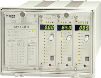
1 SPAA 341 C Feeder protection relay
2 Feeder Protection Relay Type SPAA 341 C General Features Comprehensive numerical feeder protection relay consisting of two multifunction protection relay modules and a flexible autoreclose relay module Overall scheme comprising time overcurrent protection, shortcircuit protection, phase discontinuity protection, nondirectional and directional earthfault protection, general earthfault supervision, autoreclose facilities, circuitbreaker failure protection and circuitbreaker condition monitoring 1 A and 5 A tappings on the energizing current inputs of the overcurrent and nondirectional earthfault protection and 0.2 A and 1 A tappings on the energizing inputs of the directional earthfault protection Selectable rated energizing input voltages of the directional earthfault protection: 100 V, 110 V or 120 V Four heavyduty relays for CB tripping and five weak current relays for signalling purposes Doublepole or singlepole circuitbreaker control Five configurable control inputs for the external control of the protection stages and the autoreclose module Remote control of circuitbreaker via autoreclose module Local manmachine communication via pushbuttons and a digital display on the front panels of the protection relay modules Serial interface for connecting the relay to higherlevel data acquisition systems, local or remote control systems or other host systems Local fault indication by means of LED indicators with memory functions and the digital display High immunity to electrical and electromagnetic interference Continuous selfsupervision of relay hardware and software for enhanced system reliability and availability Autodiagnostic fault indication to facilitate fault location and repair after detection of an internal relay fault Powerful software support for parametrization of the relay, for reading measured and recorded values, events, etc., and for storing readings CE marking according to the EC directive for EMC Member of the SPACOM product family and PYRAMID, ABB s coordinated protection and control concept.
3 Application The feeder protection relay SPAA 341 C is designed to be used for the protection of radial isolated neutral networks or networks earthed via a resistor or via an arc suppression coil with or without a parallel resistor. The feeder protection relay features time overcurrent protection, shortcircuit protection and phase discontinuity protection. Further, a wide choice of earthfault protection functions is available, including directional and nondirectional earthfault and residual overvoltage. The feeder protection relay also includes a flexible multishot autoreclose module for threephase autoreclosing of circuit breakers. The system reliability and availability is enhanced by a builtin circuit breaker failure protection function, a circuitbreaker condition monitor and a sophisticated hardware and software selfsupervision system. The feeder protection relay is provided with serial communication capabilities. Vital relay information is immediately available to the relay operator, locally or remotely. Therefore, the feeder protection relays can be used for any application ranging from standalone relays to advanced, fully remotecontrolled substations. Mechanical design The feeder protection relay is housed in a rigid size 300 aluminium case to IP54. The basic case design is intended for flush mounting. The case dimensions and the mounting accessories are shown on the back page. The colour of the mounting case is beige. All input and output terminals including the serial communication port are located on the rear panel. When the mounting depth is limited the flush mounting relay case can be provided with a 40 mm, 80 mm or 120 mm raising frame which reduces the depth behind the panel correspondingly. These semiflush mounted relay cases are also rear connected. The feeder protection relay is also available in a relay case for projecting mounting. Then all input and output terminals are located on the front side of the relay case. For dimensional drawings see page 11. The fully equipped feeder protection relay comprises of five modules: a connection module, an I/O module, a combined overcurrent and earthfault relay module, a directional earthfault relay module and an autoreclose relay module. The relay modules are multifunctional microprocessorbased plugin units. The feeder protection relay is available in several versions, ranging from the fully equipped feeder protection relay to versions omitting one or two modules. The relay modules are provided with local manmachine communication interfaces.
4 Module Characteristics Combined Overcurrent and Earthfault Relay Module SPCJ 4D28 I L1 I L2 I L3 I o IRF / I > I n t > [ s] k / I >> I n t >> [ s] I > >>/I n t > >> [ s] I 0 > / SGF SGB I n 3 I > I RESET STEP t 0 > [ s ] k 0 I >>/ 0 I t 0 >> [ s ]n ] I > [%] t > [ s] PROGRAM Threephase lowset overcurrent stage with definite time or inverse time characteristic for time overcurrent protection Threephase highset overcurrent stage and threephase superhighset stage with instantaneous function or definite time characteristic for shortcircuit protection Nondirectional lowset residual overcurrent stage with definite time or inverse time characteristic for earthfault protection Nondirectional highset residual overcurrent stage with definite time characteristic for earthfault protection Sensitive phase unbalance stage for detection of phase discontinuity Integrated circuitbreaker failure protection for enhanced substation operational reliability Local manmachine communication interface SGR TRIP 1719 SPCJ 4D28 Directional and Nondirectional Earthfault Relay Module SPCS 2D26 Uo I o SGF SGB ϕ U 0b > [ % ] t b > [ s ] I 01 > [%] U 01 > [%] t 1 > [ s ] I 02 > [%] U 02 > [%] t 2 > [ s ] U o I IRF RESET STEP PROGRAM Directional or nondirectional lowset residual overcurrent stage with definite time characteristic for directional earthfault protection Directional or nondirectional highset residual overcurrent stage with definite time characteristic for earthfault protection Sensitive threestage residual overvoltage protection with definite time characteristic for general earthfault supervision Integrated circuitbreaker failure protection for enhanced substation operational reliability Four selectable basic angles for the direction measuring circuit Local manmachine communication interface SGR TRIP 1721 SPCS 2D26
5 Autoreclose Module SPCT 5D54 AR1 AR2 AR3 AR4 IRF Shot 1 Shot 2 Shot 3 Shot 4 Shot 5 Final trip t r O I RESET STEP Five programmable autoreclose shots Three internal autoreclose initiation signal lines from the overcurrent and earthfault stages One external autoreclose initiation signal line Autoreclose functions initiated either by the start signal or the trip signal of a relay module In the former case the autoreclose module provides the trip signal after a programmable time delay Counters recording the number of shots initiated via separate AR lines Circuitbreaker condition monitor indicating when CB maintenance is needed Local manmachine communication interface t d SGF PROGRAM SGB SGR DEF TRIP 1722 SPCT 5D54
6 I Connection Diagram SPAA 341 C CB POS AR INH AR START AR SYNC C INH RRES CBCS I/O BS2 BS1 0 I U3 (SPCT 5D54) IRF SS1 TS1 SS2 TS2 SS3 TS3 SS4 I/O RRES BS2 BS1 U 0 I U2 (SPCS 2D26) I/O IRF SS1 TS1 SS2 TS2 SS3 TS3 SS4 RRES BS2 I> SS3 TS3 SS4 BS1 3I> I U1 (SPCJ 4D28) IRF SS1 TS1 SS2 TS2 U 12 U 23 I L1 I L2 I L3 I OB U o I O U5 U4 100 V 100 V 5 A 1 A 5 A 1 A 5 A 1 A 5 A 1 A 100/ 110/ 120 V 1 A 0.2 A ~ X X X X2 AR AR CB CTRL INH POS BS 2 BS 1 (~) P2 U aux (~) S2 S1 P1 da dn N A L1 L2 L X X2 3 4 X X2 1 2 X2 7 8 X X2 5 6 X IRF SS1 TS1 SS2 TS2 SS3 TS3 SS4 CBCS SPAZC_ I 0 0 Fig. 1. Simplified block diagram and connection diagram for the feeder protection relay SPAA 341 C SERIAL PORT (SPA) Rx Tx
7 Autoreclosure The shot pointer indicates the shot to start when the autoreclose module receives its AR initiation signal through one of the initiation lines AR1...AR4. The boxes beneath the initiation lines AR1...AR4 determine the action to be taken when an autoreclose initiation signal is received. Start means that an autoreclose shot is initiated, block means that the autoreclose shot is prevented from starting and a dash means that no action will be taken. The programmable start delay associated with the boxes in the shaded area in Fig. 2 is activated, if the autoreclose shot is initiated by the start signal of a protection stage. After the start delay the circuit breaker is opened by the autoreclose module. When the dead time has elapsed, the circuit breaker is closed and the discrimination time starts running, if employed. A new initiation signal received during the discrimination time will inhibit the whole AR sequence. An autoreclose request during the reclaim time will move the shot pointer and check whether a function has been selected or not. If not, the shot pointer moves down to the bottom horizontal line and a definite tripping will occur. At this point the AR module is blocked during the reclaim time, after which the shot pointer is reset and the module is prepared for a new AR sequence. Shot pointer Initiation signal AR1 Initiation signal AR2 Initiation signal AR3 External init. signal AR4 Circuit breaker closing Shot 1 (1) Start Start Start Start Dead time 1 td1 Shot 2 (2) Block Start Start Dead time 2 td2 Shot 3 (3) Dead time 3 td3 Shot 4 (4) Dead time 4 td4 Shot 5 (5) Dead time 5 Final Trip (6) Yes Yes No Yes Final trip function Lockout (7) Reclaim time Shot pointer = Shot 1 Ready to respond to new fault incidents Fig. 2. Simpified diagram of the AR functions of the autoreclose relay module Serial Communication The feeder protection relay is equipped with a serial communication port on the rear panel. The serial port is used for connecting the relay to the SPA bus via an optional bus connection module. Two bus connection module types are available: SPAZC17 and SPAZC21. The first one can be powered from the host relay and from a separate power source at the same time, while the other type is powered from the host relay via the D type connector. Output Relays and CB Control The feeder protection relay is provided with nine output auxiliary relays, four of which are heavyduty output relays for the direct control of the circuit breaker. Singlepole or doublepole circuit breaker control can be used. One of the five signalling relays is permanently allocated for the selfsupervision system. The functions of the other four can be defined by the user. Auxiliary Power Supply The auxiliary supply of the feeder protection relay is obtained via an internal plugin type power module. Two auxiliary power module types are available: type SPGU 240A1 for ac or dc supply within the operative voltage range V and type SPGU 48B2 for dc supply within the operative voltage range V. The power module forms the internal voltages required by the protection relay modules and the I/O module. The operation of the power module is continuously supervised.
8 Technical Data Energizing inputs Current inputs Rated current I n 0.2 A 1 A 5 A Terminal numbers X0/13 X0/12 X0/46 X0/45 X0/79 X0/78 X0/3739 X0/3738 X0/2527 X0/2526 Thermal current withstand continuously 1.5 A 4 A 20 A for 10 s 5 A 25 A 100 A for 1 s 20 A 100 A 500 A Dynamic current withstand halfwave value 50 A 250 A 1250 A Input impedance <750 mω <100 mω <20 mω Voltage inputs Rated voltage U n 100 V, 110 V or 120 V Terminal numbers X0/2829 Continuous voltage withstand 200 V Rated burden of voltage input at U n <0.5 VA Rated frequency f n, acc. to order 50 Hz or 60 Hz Output contacts Trip contacts Terminal numbers X1/1516, X2/12, 34 Rated voltage 250 V ac/dc Continuous current carrying capacity 5 A Make and carry for 0.5 s 30 A Make and carry for 3 s 15 A Breaking capacity for dc when the control circuit time constant L/R at the control voltage levels 48 V dc 5 A 110 V dc 3 A 220 V dc 1 A Contact material AgCdO 2 Signalling contacts Terminal numbers X2/56, 78, X2/1213, Rated voltage 250 V ac/dc Continuous current carrying capacity 5 A Make and carry for 0.5 s 10 A Make and carry for 3 s 8 A Breaking capacity for dc when the control circuit time constant L/R at the control voltage levels 48 V dc 1 A 110 V dc 0.25 A 220 V dc 0.15 A Contact material AgCdO 2 External control inputs Blocking inputs terminal numbers X1/12, 34 CB position message input terminal numbers X1/56 Autoreclose feedback inputs terminal numbers X1/78, 910 Control voltage Operative voltage range Current drain of activated control input V dc or V ac ma Auxiliary power supply Terminal numbers X0/6162 Power module type SPGU 240A1 rated voltages U n = 110/120/230/ 240 V ac U n = 110/125/220 V dc operative voltage range V ac/dc Power module type SPGU 48B2 rated voltages U n = 24/48/60 V dc operative voltage range V dc Power consumption, relay under quiescent/operation conditions ~10 W/~15 W Data communication Transmission mode Fibreoptic serial bus Coding ASCII Data transfer rate, selectable 4800 or 9600 Bd Electrical/optical bus connection module powered from the host relay for plastic core cables SPAZC 21BB for glass fibre cables SPAZC 21MM Electrical/optical bus connection module powered from the host relay or from an external power source for plastic core cables SPAZC 17BB for glass fibre cables SPAZC 17MM Test voltages Dielectric test voltage according to IEC 2555 Impulse test voltage according to IEC 2555 Insulation resistance according to IEC kv, 50 Hz, 1 min 5 kv, 1.2/50 µs, 0.5 J >100 MΩ, 500 V dc Disturbance tests Highfrequency (1MHz) disturbance test according to IEC , class III common mode 2.5 kv differential mode 1.0 kv Fast transients according to IEC , class III and IEC 8014, level 4 power supply inputs 4 kv, 5/50 ns other inputs 2 kv, 5/50 ns Electrostatic discharge test according to IEC and IEC 8012, class III air discharge 8 kv contact discharge 6 kv Environmental conditions Service temperature range Transport and storage temperature range according to IEC 6828 Temperature influence Damp heat test, cyclic (12 h 12 h) according to IEC C C 0.2%/ C Degree of protection by enclosure of flush mounting relay case IP 54 Weight of fully equipped relay including flush mounting relay case 25 C/55 C RH = 93%, 6 cycles ~6 kg
9 RELAY MODULE DATA Overcurrent and earthfault relay module SPCJ 4D28 Lowset overcurrent stage I> Start current I> definite time characteristic x I n inverse time characteristic x I n * 70 ms Operation characteristic definite time characteristic operate time s inverse time characteristic acc. to BS 142 and IEC 2554 special characteristic acc. to ABB practice Extremely inverse Very inverse Normal inverse Longtime inverse RItype inverse RXIDGtype inverse time multiplier k Retardation time <30 ms Dropoff/pickup ratio, typ at definite time operation characteristic class E at inverse time characteristic 5 ±3% of set current Highset overcurrent stage I>> Start current I>> x I n or, infinite Operate time s Retardation time <30 ms Dropoff/pickup ratio, typ ±3% of set current Superhighset overcurrent stage I>>> Start current I>>> x I n or, infinite Operate time s Retardation time <30 ms Dropoff/pickup ratio, typ ±3% of set current Lowset earthfault stage I 0 > Start current I 0 > x I n 70 ms Operation characteristic definite time characteristic operate time s inverse time characteristic acc. to BS 142 and IEC 2554 special characteristic acc. to ABB practice Extremely inverse Very inverse Normal inverse Longtime inverse RItype inverse RXIDGtype inverse time multiplier k Retardation time <30 ms Dropoff/pickup ratio, typ at definite time operation characteristic class E at inverse time characteristic 5 ±3% of set current Highset earthfault stage I 0 >> Start current I 0 >> x I n or, infinite 50 ms Operate time s Dropoff/pickup ratio, typ ±3% of set current Phase discontinuity protection stage I> Start current I> % x I n or, infinite 150 ms Operate time s 80 ms Dropoff/pickup ratio, typ ±2% of set value ±1 unit ±3% of set current * At inverse time characteristic the effective setting range is x I n, although setting values greater than 2.5 x I n can be set on the relay.
10 Directional earthfault relay module SPCS 2D26 Residual voltage stage U 0b > Start voltage U 0b > % of U n 60 ms Operate time t b > s 60 ms Dropoff/pickup ratio, typ ±3% of set voltage Lowset stage I 01 > or U 01 > Operation direction of stage I 01 > forward or reverse Basic angle ϕ b, selectable 90, 60, 30 or 0 Operation sector ϕ ±80 or ±88 Mode of operation of stage I 01 > directional or nondirectional Start current I 01 > % of I n Start voltage U 01 > % of U n 80 ms Operate time t 1 > s 70 ms Dropoff/pickup ratio, typ ±3% of set value x I n Autoreclose relay module SPCT 5D54 Number of autoreclose shots 1 5 AR start delay time s Dead time s Discriminating time s Reclaim time s Final trip time s Length of CB close pulse s Length of CB open pulse s ±1% of set value or ±30 ms Highset stage I 02 > or U 02 > Operation direction of stage I 02 > forward or reverse Basic angle ϕ b, selectable 90, 60, 30 or 0 Operation sector ϕ ±80 or ±88 Mode of operation of stage I 02 > directional or nondirectional Start current I 02 > % of I n or, infinite Start voltage U 02 > % of U n or, infinite 80 ms Operate time t 2 > s 70 ms Dropoff/pickup ratio, typ ±3% of set value x I n
11 Mounting and Dimensions Flush mounting relay case (dimensions in millimetres) ± ±1 Panel cutout Semiflush mounting a b Raising frame SPAZX 301 SPAZX 302 SPAZX 303 a b Mounting in 19 inch cabinets and frames An ancillary mounting plate, height 4U (~177 mm), is recommended to be used when the protection relays are to be mounted in 19 inch frames or cabinets. The ancillary mounting plate type SPAZX 304 accommodates two size 300 relays and type SPAZX 305 one size 300 relay. Projecting mounting When projecting mounting is preferred a relay case type SPAZX 317 is used. The relay case for projecting mounting is provided with front connectors. 0,4 482,6 0 (19") ø6 21,5 101,6 7 0, (4U) SPAZX 304 0,4 482,6 0 (19") 21,5 101,6 7 0, (4U) SPAZX 305
12 ABB Substation Automation Oy P.O.Box 699 FIN65101 VAASAFinland Tel Fax MRS750003MDS EN
Feeder protection relay
 Page 1 Issued: April 1999 Status: New Data subject to change without notice Features Comprehensive numerical feeder protection relay consisting of two multi-function protection relay modules and a flexible
Feeder protection relay SPAA 341 C. Product Guide
 Issued: April 1999 Status: Updated Version: D/07.03.2006 Data subject to change without notice Features Comprehensive numerical feeder protection relay consisting of two multi-function protection relay
Feeder protection relay SPAA 121 C. Product Guide
 Issued: April 1999 Status: Updated Version: C/06.03.2006 Data subject to change without notice Features Two-phase low-set phase overcurrent unit with definite time or inverse time characteristic Two-phase
Residual overvoltage relay
 Page 1 Issued: April 1999 Status: New Data subject to change without notice Features Definite-time residual overvoltage earthfault protection and supervision Two independent operation stages, e.g. one
Sensitive definite time or inverse time earth-fault stage for back-up residual earthfault
 Issued: April 1999 Status: Updated Version: B/09.11.2001 Data subject to change without notice Features Sensitive restricted earth-fault protection stage for fast, selective earth-fault protection Sensitive
Combined Overcurrent and Earth-fault Relay SPAJ 140 C. Product Guide
 Combined Overcurrent and Earth-fault Product Guide Issued: April 1999 Status: Updated Version: C/18.04.2006 Data subject to change without notice Features Three-phase, low-set phase overcurrent unit with
Earth-fault Relay SPAJ 110 C. Product Guide
 Issued: April 1999 Status: Updated Version: C/12.04.2006 Data subject to change without notice Features Low-set neutral overcurrent stage with definite time or inverse time characteristic High-set neutral
Sensitive Earth-fault Relay SPAJ 111 C. Product Guide
 Issued: April 1999 Status: Update Version: C/12.04.2006 Data subject to change without notice Features Sensitive low-set neutral overcurrent stage with definite time characteristic High-set neutral overcurrent
Combined Overcurrent and Earth-fault Relay SPAJ 141 C. Product Guide
 Combined Overcurrent and Earth-fault Product Guide Issued: April 1999 Status: Updated Version: C/19.04.2006 Data subject to change without notice Features Three-phase, low-set phase overcurrent unit with
Synchro-check relay. Application
 Issued: April 1999 Status: Updated Version: B/08.11.2001 Data subject to change without notice Features Two identical operation stages allowing the closing conditions of two separate circuit breakers to
Voltage regulator. SPAU 341 C 1MRS MBG Issued: July 1998 Status: Revised Version: C/ Data subject to change without notice
 Issued: July 1998 Status: Revised Version: C/08.10.2003 Data subject to change without notice Features Comprehensive voltage regulation for power transformers with on-load tapchangers in distribution substations
High impedance protection relay
 High impedance protection relay Page 1 Issued: April 1999 Status: New Data subject to change without notice Features High impedance type differential current earth-fault protection, so called restricted
Arc protection relay. Features Three-phase overcurrent function. Application
 Arc protection relay REA 10_ Page 1 Issued: May 1999 Status: New Data subject to change without notice Features Three-phase overcurrent function Loop-type or radial sensor fibre for arc detection Two high-speed
High Impedance Protection Relay SPAE010, SPAE011. Product Guide
 SPAE010, SPAE011 SPAE010, SPAE011 1MRS750383-MBG Issued: April 1999 Status: Updated Version: D/21.03.2006 Data subject to change without notice Features High impedance type differential current earth-fault
Arc protection relay. Features Three-phase overcurrent function. Application
 Arc protection relay REA 10_ Issued: May 1999 Status: Updated Version: B/12.11.2001 Data subject to change without notice Features Three-phase overcurrent function Loop-type or radial sensor fibre for
Directional or Non-Directional Earth-Fault Relay REJ 527. Product Guide
 Directional or Non-Directional Earth-Fault Product Guide Issued: 17.06.19994 Status: Updated Version: C/16.10.2002 Data subject to change without notice Features Directional or non-directional low-set
Feeder Protection Relay REF 610. Product Guide
 Product Guide Contents 1 Description.............................. 3 2 Protection functions....................... 3 3 Measurement............................ 4 4 Disturbance recorder......................
IRI1-ES Sensitive Earth Fault Current Relay. Manual IRI1-ES (Revision A)
") IRI1-ES Sensitive Earth Fault Current Relay Manual IRI1-ES (Revision A) Woodward Manual IRI1-ES GB Woodward Governor Company reserves the right to update any portion of this publication at any time. Information
IRI1-ES Sensitive Earth Fault Current Relay Manual IRI1-ES (Revision A) Woodward Manual IRI1-ES GB Woodward Governor Company reserves the right to update any portion of this publication at any time. Information
Motor Protection Relay REM 610. Product Guide
 Product Guide Contents 1 Description.............................. 3 2 Protection functions....................... 3 3 Measurement............................ 4 4 Disturbance recorder......................
Protection Relays PHASE & RESIDUAL OVERCURRENT
 Protection Relays PHASE & RESIDUAL OVERCURRENT Application The relay type NA016 can be used in radial networks as feeder or power transformer protection. In solidly grounded systems the residual overcurrent
SIPROTEC easy 7SJ45 Numerical Overcurrent Protection Relay Powered by CTs
 SIPROTEC easy 7SJ4 Numerical Overcurrent Protection Relay Powered by CTs Function overview Fig. /1 Description The SIPROTEC easy 7SJ4 is a numerical overcurrent protection relay which is primarily intended
Relion 605 series. Self-powered feeder protection REJ603 Product Guide
 Relion 605 series Relion 605 series Relion 605 series Self-powered feeder protection Product Guide Product version: 3.0 Contents 1. Description... 3 2. Relay functions... 3 3. Protection functions... 4
Communication Gateway COM 610. Product Guide
 Communication Gateway COM 610 Product Guide Issued: September 2004 Status: Updated Version: D/17.10.2006 Data subject to change without notice Features Protocol conversion gateway for substation automation:
Electronic timer CT-ARE OFF-delayed without auxiliary voltage, 1 c/o (SPDT) contact
 contact") Data sheet Electronic timer CT-ARE OFF-delayed without auxiliary voltage, 1 c/o (SPDT) contact The CT-ARE is an electronic time relay with OFF-delay. It is from the CT-E range. The CT-E range is the economic
Data sheet Electronic timer CT-ARE OFF-delayed without auxiliary voltage, 1 c/o (SPDT) contact The CT-ARE is an electronic time relay with OFF-delay. It is from the CT-E range. The CT-E range is the economic
Relion 611 series. 611 series Type Test Certificate
 Relion 611 series 611 series Document ID: 1MRS757466 Issued: 2016-02-22 Revision: B Product version: 2.0 Copyright 2016 ABB. All rights reserved Table of contents Table of contents Section 1 Section
High-Tech Range IRI1-ES- Sensitive Earth Fault Current Relay
 High-Tech Range IRI1-ES- Sensitive Earth Fault Current Relay IE ON RESET.5 X1 t IE X1.6%.2.4.8 1.6 X1.1s.2.4.8 1.6 X2 OFF ON S1 S2 IRI1-ES IRI1-ES C&S Electric Limited (Protection & Control Division) Contents
General characteristics of C-type relay modules
 General characteristics of C-type relay modules User s manual and Technical description B I > I >> Indicators for measured values I L1 I L2 I L3 IRF Self-supervision alarm indicator (Internal Relay Fault)
Switching relay CT-IRE with 1 c/o (SPDT) contact
 contact") Data sheet Switching relay CT-IRE with 1 c/o (SPDT) contact The CT-IRE is a switching relay from the CT-E range. The CT-E range is the economic range of ABB s time relays and offers a cost effective price-performance
Data sheet Switching relay CT-IRE with 1 c/o (SPDT) contact The CT-IRE is a switching relay from the CT-E range. The CT-E range is the economic range of ABB s time relays and offers a cost effective price-performance
Type MVTT 14 and MVTT 15: Static Digital Time delay relays
 Type MVTT 4 and MVTT 5: Static Digital Time delay relays Features 000/ setting range Time settings easily selected by means of thumbwheel switches Provide time delayed pick-up, or drop-off Compact construction
Multifunction Transducer MT440
 Multifunction Transducer MT440 Voltage and current auto range measurements up to 600V, 12.5A Universal wide auxiliary power supply range 24 300 Vdc, 40 276 Vac Power accuracy class 0.5 (EN 60 688), Up
INTRODUCTION. The PL-50 MO and PM-250 families represent the. PM-250-H: Horizontal box. PM-250-V: Vertical box
 INTRODUCTION The PL-50 MO units are available in the next mechanical version: The PL-50 MO and PM-250 families represent the different solutions that Team Arteche offers for motor protection. Both families
Binary output and supervision 520CSD01 Data sheet
 RTU520 product line Binary output and supervision 520CSD01 Data sheet R01 C01 O01 R02 O02 RTU I/O bus ERR Microcontroller RAM Flash IOC Output register DC DC (1 out of n) check Output state monitoring
ekorrps MULTIFUNCTIONAL PROTECTION UNIT CONFIGURATION AND GENERAL CHARACTERISTICS LIB
 MO-067-EN Operation Manual MULTIFUNCTIONAL PROTECTION UNIT CONFIGURATION AND GENERAL CHARACTERISTICS LIB Transformer Substations Secondary Distribution Switchgear Primary Distribution Switchgear Protection
Relion 610 series. Feeder Protection REF610 Product Guide
 Relion 610 series Feeder Protection Product Guide Contents 1. Description...3 2. Functional overview...3 3. Protection functions...5 4. Application...5 5. Measurement...8 6. Disturbance recorder...8 7.
Feeder Protection REF615. Product Guide
 Product Guide Contents 1 Description.............................. 3 2 Standard configurations................. 3-4 3 Protection functions.................... 4-5 4 Application...........................
Electronic timer CT-AHS OFF-delayed with 2 c/o contacts Data sheet
 2CDC 251 113 F0004 CT-AHS 1 7 2 6 5 4 8 3 1 10 selectable time ranges, from 0.05 s to 300 h 2 Potentiometer with direct reading scale for the fine adjustment of the time delay 3 Sliding switch to set the
XE2 DC current relay for loss of excitation protection. Manual XE2 (Revision A)
") XE2 DC current relay for loss of excitation protection Manual XE2 (Revision A) Woodward Manual XE2 GB Woodward Governor Company reserves the right to update any portion of this publication at any time.
XE2 DC current relay for loss of excitation protection Manual XE2 (Revision A) Woodward Manual XE2 GB Woodward Governor Company reserves the right to update any portion of this publication at any time.
Electronic timer CT-ARS.11
 2CDC 251 088 F0t07 Features Rated control supply voltage 24 240 V AC/DC Single function OFF delay timer without auxiliary voltage One device includes 7 time ranges (0.05 s 10 min) 1 c/o (SPDT) contact
DGSZV-EP DIGITAL GALVANIC LONGITUDINAL DIFFERENTIAL PROTECTION. Application field
 DGSZV-EP DIGITAL GALVANIC LONGITUDINAL DIFFERENTIAL PROTECTION The digital galvanic longitudinal differential protection of type DGSZV-EP is part of device family named EuroProt. This short description
Protection relays.
 Protection relays www.vamp.fi Vamp Ltd Vamp Ltd, with a strong experience of designing devices, is an independent supplier of relays and monitoring equipment. The company has an established reputation
Contact protection relay
 Contact protection relay Ordering details SVR 450 08 F0000 The protects sensitive control contacts from excessive load. It can be used with latching function or without. Bounce time of control contacts
Electronic timer CT-EAS ON-delayed and OFF-delayed with 1 c/o contact Data sheet
 2CDC 251 116 F0004 1 5 2 4 3 6 Characteristics Single-function ON-delay and OFF-delay timer One device includes 10 time ranges, from 0.05 s to 300 h, for the adjustment of the time delay Remote potentiometer
DRTS 66. The new generation of advanced test equipments for Relays, Energy meters, Transducers and Power quality meters
 The new generation of advanced test equipments for Relays, Energy meters, Transducers and Power quality meters Testing all relay technologies: electromechanical, solid state, numerical and IEC61850 Manual
Electronic timer CT-VBS OFF-delayed without auxiliary voltage, for DC contactors Data sheet
 Characteristics Single-function OFF-delay timer for DC contactors, without auxiliary voltage Width.5 mm CDC 5 6 F Approvals a culus f CCC CT-BS Circuit diagram Marker label Marks g c CE C-Tick Order data
PROTECTION RELAYS THE ULTRA LINE NUMERICAL MULTIFUNCTION INTELLIGENT DEVICE FOR PROTECTION, SUPERVISION, METERING AND CONTROL
 MICROPROCESSOR PROTECTION RELAYS THE ULTRA LINE NUMERICAL MULTIFUNCTION INTELLIGENT DEVICE FOR PROTECTION, SUPERVISION, METERING AND CONTROL MICROELETTRICA SCIENTIFICA MANUFACTURES A COMPLETE RANGE OF
GRD130 - FEATURES APPLICATION
 FEATURES Phase undervoltage protection with IDMTL or DTL. Phase overvoltage protection with IDMTL or DTL. Zero phase sequence overvoltage (neutral voltage displacement) protection with IDMTL/DTL. Negative
1S20. Arc Fault Monitor Relay. Features. Introduction. ARC Fault Protection
 Technical Bulletin Arc Fault Monitor Relay Features Compact, economic design Simple panel mounting for retrofit applications Two or three arc sensor inputs Two high speed tripping duty arc sense output
Electronic timer CT-AHD.22
 2CDC 251 093 F0t06 a Rotary switch for the preselection of the time range b Potentiometer with direct reading scale for the fine adjustment of the time delay c U: green LED V control supply voltage applied
BE1-50/51M TIME OVERCURRENT RELAY ADVANTAGES
 BE1-50/51M TIME OVERCURRENT RELAY The BE1-50/51M Time Overcurrent Relay provides economical overload and fault protection for generators, transformers, lines and motors. ADVANTAGES Self powered from 50/60Hz
Electronic timer CT-ARS.11 OFF-delayed without auxiliary voltage with 1 c/o (SPDT) contact
 contact") Data sheet Electronic timer CT-ARS.11 OFF-delayed without auxiliary voltage with 1 c/o (SPDT) contact The CT-ARS.11 is an electronic timer from the CT-S range with true OFF-delay. It provides 7 time ranges
Data sheet Electronic timer CT-ARS.11 OFF-delayed without auxiliary voltage with 1 c/o (SPDT) contact The CT-ARS.11 is an electronic timer from the CT-S range with true OFF-delay. It provides 7 time ranges
Electronic timer CT-ERS.12 ON-delayed with 1 c/o contact Data sheet
 2CDC 251 056 F0t07 Features Rated control supply voltage 24-48 V DC, 24-240 V AC Single-function ON-delay timer One device includes 10 time ranges (0.05 s - 300 h) 1 c/o contact 2 LEDs for status indication
DRTS 33. The new generation of advanced three phase relay test set
 The new generation of advanced three phase relay test set Testing all relay technologies: electromechanical, solid state, numerical and IEC61850 Local control with color display Simultaneously available:
Electronic timer CT-APS.21 OFF-delayed with 2 c/o (SPDT) contacts
 contacts") Data sheet Electronic timer CT-APS.21 OFF-delayed with 2 c/o (SPDT) contacts The CT-APS.21 is an electronic timer from the CT-S range with OFF-delay. It provides 10 time ranges and a continuous rated control
Data sheet Electronic timer CT-APS.21 OFF-delayed with 2 c/o (SPDT) contacts The CT-APS.21 is an electronic timer from the CT-S range with OFF-delay. It provides 10 time ranges and a continuous rated control
APU 200 Automatic DATA SHEET Gen-set Controller DATA SHEET
 APU 200 Automatic DATA SHEET Gen-set Controller DATA SHEET Measurement input, auto range Up to 1000 V AC L-L Up to 12.5 A (sinusoidal) 16 400 Hz Output Up to four analogue outputs Relay output RS 485 Modbus
Switching relay CT-IRS with 1, 2 or 3 c/o contacts Data sheet
 1SVR 430 221 F7300 2 1 3 Characteristics Switching relay ON-delay approx. 10 ms 1, 2 or 3 c/o contacts Switching relay with gold-plated contacts Width 22.5 mm Approvals e f GOST CCC CT-IRS 1 U/R: green
Electronic timer CT-ERS.21
 2CDC 251 057 F0t07 Features Rated control supply voltage 24 240 V AC/DC Single function ON delay timer One device includes 10 time ranges (0.05 s 300 h) 2 c/o contacts 2 LEDs for status indication Width
Electronic timer CT-ERD.12
 2CDC 251 092 F0t06 a Rotary switch for the preselection of the time range b Potentiometer with direct reading scale for the fine adjustment of the time delay c U: green LED V control supply voltage applied
For Transmission, Distribution and Machinery protection.
 Founded in 1953, Microelettrica Scientifica has developed a wide range of products, divided into three main lines: For Transmission, Distribution and Machinery protection. A-Line Electronic analogic. M-Line
MRA1 Trip circuit supervision. Manual MRA1 (Revision A)
") MRA1 Trip circuit supervision Manual MRA1 (Revision A) Woodward Manual MRA1 GB Woodward Governor Company reserves the right to update any portion of this publication at any time. Information provided by
MRA1 Trip circuit supervision Manual MRA1 (Revision A) Woodward Manual MRA1 GB Woodward Governor Company reserves the right to update any portion of this publication at any time. Information provided by
DRTS 64. The new generation of advanced test equipment for Relays, Energy meters, Transducers and Power quality meters.
 The new generation of advanced test equipment for Relays, Energy meters, Transducers and Power quality meters Testing all relay technologies: electromechanical, solid state, numerical and IEC61850 Manual
DRTS 33. The new generation of advanced test equipments for Relays, Energy meters, Transducers and Power quality meters
 The new generation of advanced test equipments for Relays, Energy meters, Transducers and Power quality meters Testing all relay technologies: electromechanical, solid state, numerical and IEC61850 Manual
Reyrolle Protection Devices. 7SG21 DDB20 Multi Range Digital Setting Time Delay Relay. Energy Management
 Reyrolle Protection Devices 7SG21 DDB20 Multi Range Digital Setting Time Delay Relay Energy Management 7SG21 DDB20 Digital Time Delay Induction disc reset emulation Replacement of induction disc timing
2C138. Sensitive Earth Fault Relay. Features. Application. Operation
 Technical Bulletin 2C138 Sensitive Earth Fault Relay Features High sensitivity (0.1% of I n ) 2 nd & 3rd harmonic & HF noise suppression - tuned to 50 Hz Optional reset functions Instantaneous (Fast),
Reyrolle Protection Devices. 7SG117 Argus 7 Synchronising Relay. Answers for energy
 Reyrolle Protection Devices 7SG117 Argus 7 Synchronising Relay Answers for energy 7SG117 Argus 7 Synchronising Relay Fig 1. Independent check & system synchronising settings Adjustable slip frequency,
Voltage Transducer UMT516 / MT516
 Voltage Transducer UMT516 / MT516 True RMS AC voltage measurements Voltage auto range measurements up to 600V # Wide frequency measurement range 16 400 Hz High accuracy class 0.2 (IEC-688), 0.1 on communication
Protection and control. Sepam range Sepam 100 RT. Merlin Gerin Square D Telemecanique
 Protection and control epam range epam T Merlin Gerin quare D Telemecanique presentation contents page presentation connection characteristics installation ordering information epam T. on in in in in in
SPA-ZC 200/SPA-ZC 202 IEC /SPA-gateway Modules. Installation Manual
 Issued: 29.03.2001 Version: A/29.03.2001 Checked: M.K. Approved: We reserve the right to change data without prior notice. Contents: 1. Safety information...4 2. Introduction...5 2.1. Contents of delivery...5
SPA-ZC 17. Bus connection module SPA-ZC 17. User s manual and Technical description. Tx SC Rx BB BM MB MM SPA / RS 485 POWER SLAVE 1 MASTER 0
 SPA-ZC 17 Bus connection module User s manual and Technical description 1 2 3 4 5 6 7 8 O N SPA / RS 485 SPA 1100000 RS 485 0011110 SLAVE 1 MASTER 0 Tx SC Rx 2 5 Uaux 80...265 V ~ 18...80 V SPA-ZC 17 RS
Electronic timer CT-ARS.21 OFF-delayed without auxiliary voltage with 2 c/o (SPDT) contacts
 contacts") Data sheet Electronic timer CT-ARS.21 OFF-delayed without auxiliary voltage with 2 c/o (SPDT) contacts The CT-ARS.21 is an electronic timer from the CT-S range with true OFF-delay. It provides 7 time ranges
Data sheet Electronic timer CT-ARS.21 OFF-delayed without auxiliary voltage with 2 c/o (SPDT) contacts The CT-ARS.21 is an electronic timer from the CT-S range with true OFF-delay. It provides 7 time ranges
LON bus communication devices 1MRS MBG Page 1 Issued: April 1999 Status: New Data subject to change without notice
 LON bus communication devices Page 1 Issued: April 1999 Status: New Data subject to change without notice Features The LonWorks Network is an open system adapted for various application areas Peer-to-peer
7SG26 Tau Autoreclose and synchronization Answers for energy
 Reyrolle Protection Devices SG Tau Autoreclose and synchronization Answers for energy SG Tau Autoreclose and synchronization Fig 1. Tau relay in size 1 case Description The Tau range of auto-reclosing
2T105. Multi Range Digital Setting Time Delay Relay. Features. Application. Operation
 2T15 Multi Range Digital Setting Time Delay Relay Technical Bulletin Features Four time ranges -.99s, -9.9s, -99s, -99s High accuracy & repeatability timing compensated for output relay delay Time settings
RE17LAMW on-delay timing relay - 1 s..100 h V AC/ DC - solid state output
 Characteristics on-delay timing relay - 1 s..100 h - 24..240 V AC/ DC - solid state output Main Range of product Product or component type Discrete output type Width Component name Time delay type Time
Data communication and reporting unit
 FAULT SRIO 1000M Data communication and reporting unit User s manual and Technical description SRIO 1000M ON 1 2 SERIAL IF 4 LOCAL 1 2 3 4 5 6 7 8 1 0 0543A 1MRS 750533-MUM EN Issued 1996-10-23 Modified
SPA-ZC 302. Profibus-DPV1/SPA Gateway. Product Guide. spa-zc302_rightco300
 Profibus-DPV1/SPA Gateway SPA-ZC 302 Product Guide spa-zc302_rightco300 Issued: 25.11.2003 Status: Updated Version: D/16.05.2008 Data subject to change without notice Features Profibus DP Version 1 connectivity
Relays for Various Protection Applications / 7SV600
 Relays for Various Protection Applications / SV00 SIPROTEC SV00 numerical circuit-breaker failure protection relay Fig. 0/ Description SIPROTEC SV00 numerical circuit-breaker failure protection relay The
Relion 615 series. Feeder Protection and Control REF615 Product Guide
 Relion 615 series Feeder Protection and Control Product Guide Contents 1. Description...3 2. Standard configurations...3 3. Protection functions...7 4. Application...9 5. Supported ABB solutions...12 6.
RE22R2CMR Off-delay Timing Relay s 300h V AC/DC - 2C/O
 Characteristics Off-delay Timing Relay - 0.05s 300h - 24 240V AC/DC - 2C/O Main Range of product Product or component type Discrete output type Device short name Nominal output current Complementary Contacts
Electronic timer CT-AWS Impulse-OFF with 2 c/o contacts Data sheet
 CDC 51 1 F000 1 7 6 5 8 Characteristics Single-function impulse-off timer One device includes 10 time ranges, from 0.05 s to 00 h, for the adjustment of the pulse time c/o contacts nd c/o contact can be
RM4JA01F current measurement relay RM4-J - range ma V AC
 Characteristics current measurement relay RM4-J - range 3..1000 ma - 110..130 V AC Main Range of product Product or component type Relay type Relay name Relay monitored parameters Power consumption in
DGBV-EP DIGITAL GENERATOR AND GENERATOR-TRANSFORMER UNIT PROTECTION. Field of application
 DGBV-EP DIGITAL GENERATOR AND GENERATOR-TRANSFORMER UNIT PROTECTION Field of application The devices of the EuroProt complex protection family are modular devices. The modules are selected, assembled and
LED Driver Linear / area fixed output
 Driver C 38W 5-7mA flexc lp ACED series Product description Built-in constant current ED Driver Adjustable output current between 5 and 7 ma Max. output power 38 W Up to 85 % efficiency ominal life-time
INSTRUCTION MANUAL TRIP CIRCUIT SUPERVISION RELAY GKAD1
 INSTRUCTION MANUAL TRIP CIRCUIT SUPERVISION RELAY GKAD1 TOSHIBA Corporation 2004 All Rights Reserved. ( Ver. 1.6 ) Safety Precautions Before using this product, please read this chapter carefully. This
DTRV-EP. COMPLEX DIGITAL PROTECTION FOR 120 kv / MEDIUM VOLTAGE TRANSFORMERS. Application field
 DTRV-EP COMPLEX DIGITAL PROTECTION FOR 120 kv / MEDIUM VOLTAGE TRANSFORMERS Application field The DTRV type of complex transformer protection is designed to protect 120 kv / medium voltage transformers,
XU1-E Earth fault voltage relay. (August 1996) Manual XU1-E (Revision New)
 Manual XU1-E (Revision New)") XU1-E Earth fault voltage relay (August 1996) Manual XU1-E (Revision New) Woodward Manual XU1-E GB Woodward Governor Company reserves the right to update any portion of this publication at any time. Information
XU1-E Earth fault voltage relay (August 1996) Manual XU1-E (Revision New) Woodward Manual XU1-E GB Woodward Governor Company reserves the right to update any portion of this publication at any time. Information
MiCOM P122C Time-Overcurrent Protection
 Protection Relays 01 MiCOM P122C Time-Overcurrent Protection Customer Benefits 1A/5A software setting 4 function keys Compact unit for flush and wall-surface mounting Comprehensive measurements Disturbance
RE22R2AMR On-delay Timing Relay s 300h V AC/DC - 2C/O
 Characteristics On-delay Timing Relay - 0.05s 300h - 24 240V AC/DC - 2C/O Main Range of product Product or component type Discrete output type Device short name Nominal output current Complementary Contacts
TU531, TU532 Terminal Unit
 Ordering Data DATA SHEET TU531, TU532 Terminal Unit 1 Ordering Data Part No. Description Product Life Cycle Phase *) 1SAP 217 200 R0001 1SAP 217 000 R0001 1SAP 417 000 R0001 TU531, terminal unit, 230 VAC,
RE22R2KMR Off-delay Timing Relay s 10min V AC/DC - 2C/O
 Characteristics Off-delay Timing Relay - 0.05s 10min - 24 240V AC/DC - 2C/O Main Range of product Product or component type Discrete output type Device short name Nominal output current Complementary Contacts
Data communication and reporting unit
 SRIO 500M Data communication and reporting unit User s manual and Technical description SRIO 500M FAULT ON 1 2 SERIAL IF 4 LOCAL 1 2 3 4 5 6 7 8 1 0 0542A 1MRS 750540-MUM EN Issued 1996-10-23 Modified
02/11/2015
 DIN Rail Mount 35 mm HSV Part number 84874320 Control of overspeed, underspeed, operating rate, stopping Measurement via discrete sensors - 3-wire PNP or NPN, Namur, voltage 0-30V or volt-free contact
RUC industrial relays of small dimensions
 RUC industrial relays of small dimensions 135 with adaptor (V) Contact data Number and type of contacts Contact material Rated / max. switching voltage Min. switching voltage Rated load Min. switching
Thermistor motor protection relays CM-MSS.12 and CM-MSS.13
 Data sheet Thermistor motor protection relays CM-MSS.12 and CM-MSS.13 The thermistor motor protection relays CM-MSS.12 and CM-MSS.13 monitor the winding temperature of motors and protect them from overheating,
Single-phase ( V) voltage monitoring: Undervoltage Overvoltage Window mode (overvoltage + undervoltage) Voltage fault memory selectable
 voltage monitoring: Undervoltage Overvoltage Window mode (overvoltage + undervoltage) Voltage fault memory selectable") 70 Series - Line monitoring relay 70 Features 70.11 70.31 70.41 Electronic voltage monitoring relays for single and three-phase applications Multifunctional types, providing the flexibility of monitoring
70 Series - Line monitoring relay 70 Features 70.11 70.31 70.41 Electronic voltage monitoring relays for single and three-phase applications Multifunctional types, providing the flexibility of monitoring
Voltage monitoring relays CM-ESS.1 For single-phase AC/DC voltages
 Data sheet Voltage monitoring relays CM-ESS.1 For single-phase AC/DC voltages The CM-ESS.1 is an electronic voltage monitoring relay that provides reliable monitoring of voltages as well as detection of
LED Driver Linear / area fixed output
 Driver C 57W 8-5mA flexc lp ACED series Product description Built-in constant current ED Driver ew version DC operating with E marking Adjustable output current between 8 and,5 ma Max. output power 57
RE Product data sheet Characteristics. universal plug-in timing relay - flashing s..60 mn V AC - 2 OC. Main.
 Characteristics universal plug-in timing relay - flashing - 0.1 s..60 mn - 24..240 V AC - 2 OC Main Range of product Product or component type Discrete output type Contacts type and composition Width pitch
Electronic timer CT-EBD.12 Flasher starting with ON with 1 c/o (SPDT) contact
 contact") Data sheet Electronic timer CT-EBD.12 Flasher starting with ON with 1 c/o (SPDT) contact The CT-EBD.12 is an electronic time relay with the function flasher starting with ON. It is from the CT-D range.
Data sheet Electronic timer CT-EBD.12 Flasher starting with ON with 1 c/o (SPDT) contact The CT-EBD.12 is an electronic time relay with the function flasher starting with ON. It is from the CT-D range.
NPW800R RETROFITTING. Power and Volatge Protection Relay
 RETROFITTING Power and Volatge Protection Relay NPW800R (R3 case) is dedicated to the refurbishment of CEE WTG 7000 relays (R3 case) providing the measurement of apparent (S), active (P) and reactive (Q)
LED Driver Linear / area fixed output
 Driver LC 69W 35-5mA flexc lp ANCED series Product description Built-in constant current LED Driver New version DC operating with EL marking Adjustable output current between 35 and 5 ma Max. output power