Siemens AG KD Switch Disconnectors SENTRON. Edition December Answers for infrastructure and cities.
|
|
|
- Silvester Cox
- 5 years ago
- Views:
Transcription


1 KD Switch Disconnectors SENTRON Edition December 01 Answers for infrastructure and cities.


2 Related catalogs Low-Voltage Power Distribution and LV 10 Electrical Installation Technology SENTRON SIVACON ALPHA Protection, Switching, Measuring and Monitoring Devices, Switchboards and Distribution Systems E86060-K880-A101-A Standard-Compliant Components LV 11 for Photovoltaic Systems SENTRON SIVACON ALPHA Contents Air circuit breakers Molded case circuit breakers Miniature circuit breakers Residual current protective devices / AFD units Fuse systems Overvoltage protection devices Switch disconnectors Switching devices Transformers, power supply units and socket outlets Busbar systems Measuring devices and power monitoring Monitoring devices Software Switchboards Busbar trunking systems System cubicles, system lighting and system air-conditioning Distribution boards Molded-plastic distribution systems ipo installation terminals Products for the DC side Products for the AC side Measuring and monitoring devices Distribution systems and system cubicles Terminal blocks E86060-K870-A101-A-7600 SIVACON LV 50 System Cubicles, System Lighting and System Air-Conditioning System overview Cubicle racks Enclosures Cubicle expansions Preconfigured cubicles Special cubicles System lighting System air-conditioning PDF (E86060-K190-A101-A5-7600) ALPHA FIX LV 5 Terminal Blocks ipo plug-in terminals ipo installation terminals Spring-loaded terminals Combination plug-in terminals Insulation displacement terminals Screw terminals Accessories for terminal blocks E86060-K185-A101-A-7600 Products for Automation and Drives CA 01 Interactive Catalog, DVD All products of automation and drives technology and of lowvoltage power distribution and electrical installation technology E86060-D4001-A510-D-7600 Industry Mall Information and Ordering Platform in the Internet: All products of automation and drives technology and of lowvoltage power distribution and electrical installation technology Catalog PDF All catalogs for low-voltage power distribution and electrical installation technology can be downloaded as PDF files and e-books. Internet: Trademarks All product designations may be registered trademarks or product names of Siemens AG or other supplying companies. Third parties using these trademarks or product names for their own purposes may infringe upon the rights of the trademark owners. Further information about low-voltage power distribution and electrical installation is available on the Internet at: Technical Support Expert advice on technical questions with a wide range of demand-optimized services for all our products and systems. Siemens 01

3 SENTRON KD Switch Disconnectors Introduction 1 KD Switch Disconnectors up to 1600 A The products and systems listed in this catalog are developed and manufactured in accordance with a VDE-certified quality management system complying with EN ISO 9001:000.. Appendix Refer to the Industry Mall for current updates of this catalog: Siemens AG 01 Printed on paper from sustainably managed forests and controlled sources.


4 The right one for everyone Our portfolio includes switchboards, distribution boards, protection, switching, measuring and monitoring devices, switches and socket outlets. All over the world, the universality, modularity and intelligence of our components and systems give you innumerable benefits all the time they are in use. Developed according to the respective international standards, we offer forward-looking design with innovative functions and ensure the highest quality standards world-wide Sustainability in focus As a worldwide leader in the provision of high-quality, standards-compliant products and systems for low-voltage power distribution, we contribute to the sustainable and responsible handling of electrical energy. With our integrated portfolio which ranges from power supply and distribution, through short-circuit protection and overload protection through to power monitoring, we support the implementation of environmentally friendly energy concepts on the basis of wind power, photovoltaics, intelligent buildings and electromobility. Siemens 01

5 Universal, safe and intelligent power distribution Whether in industrial plants, in infrastructure or in buildings: every technical plant depends on the reliable supply of electricity. Our products provide a safe, reliable and efficient electrical infrastructure at the medium- and low-voltage levels. Our components reliably protect against accidents, disturbances and fires caused by electrical installations and allow consumers to utilize electrical power in a sustainable, responsible manner. We are happy to help you with comprehensive support from the initial information through to operation. Everything for power distribution Consistent solutions are required for electrical power distribution in buildings. Our answer is Totally Integrated Power (TIP). TIP stands for innovative products, systems and software tools which ensure the safe and reliable distribution of electric power. They are supplemented by communication-capable circuit breakers and modules which connect the power distribution system to the building automation system or industrial automation solutions. These in turn can be linked to a comprehensive energy management system which contributes to optimizing the consumption of electricity and hence to lowering the costs of operation. Excellent support As a competent and reliable partner, we also offer you comprehensive support from the initial information, through planning, configuring and ordering to commissioning, operation and technical support. We know the needs of your working environment and your daily business. Based on this, we give you flexible and high quality support, which allows you to concentrate on your customers and their needs. Siemens 01

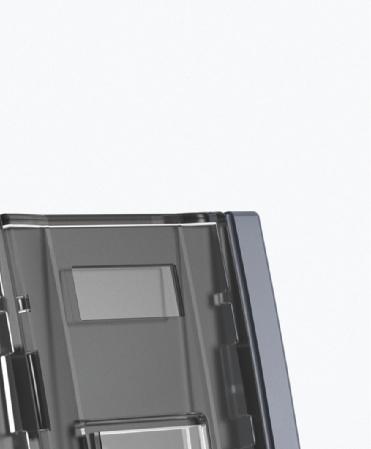
6 The new KD switch disconnectors provide reliable protection for personnel and ensure high system availability in buildings, infrastructure and industrial plants. With these switch disconnectors you can implement your projects more efficiently and thus safeguard your competitiveness. Avoid electrical accidents The KD switch disconnectors are designed to systematically avoid electrical accidents. For example when maintenance work is being carried out on machines, you can help to prevent unauthorized operation by means of appropriate locking functions. The terminal covers of the KD switch disconnectors ensure enhanced touch protection and prevent electric shocks. Thanks to transparent contact covers, contact positions are clearly visible at all times. Increase productivity The KD switch disconnectors provide fast and easy installation. Additional functions can be retrofitted at any time thanks to their modular design and a comprehensive range of accessories. Easy ordering and fast delivery also contribute to optimized stockkeeping. You therefore benefit from reduced time and low costs. You can even work much more efficiently during the planning phase: You will be provided with all the CAx data relevant for the entire engineering process. Improve flexibility The wide variety of applications of the KD switch disconnectors will enable you to satisfy all your requirements whether as main control, EMERGENCY-STOP or maintenance switches. This is supported by a large selection of possible connection methods and operating mechanism designs and the comprehensive accessories. 4 Siemens 01


7 KD switch disconnector as maintenance switch in plants for safe operation during maintenance work in voltage-free state KD switch disconnector as EMERGENCY-STOP switch in a production plant for protection of operating personnel KD switch disconnector as main control switch in floor distribution system for isolation from the supply Siemens 01 5


8 Highlights Compact outer dimensions for optimum space utilization in the power distribution board, control cabinet or distribution board. Retrofitting an N or an N/PE terminal or an additional pole as a 4th contact element is a fast, easy operation thanks to the modular design of the switch disconnector. Wide variety of applications thanks to a range of different operating mechanism designs: Side operating mechanism or front operating mechanism positioned in the center, or to the left of the switch disconnector. The control circuitry can be function-tested by means of the auxiliary switch test function. High level of protection for personnel and plant, even in confined installation spaces, afforded by locking functions. KD switch disconnectors up to 00 A can be mounted on standard mounting rails for speedy installation. 6 Siemens 01
9 Introduction 11 KD Switch Disconnectors 1/ General data 1/6 Technical features Siemens 01
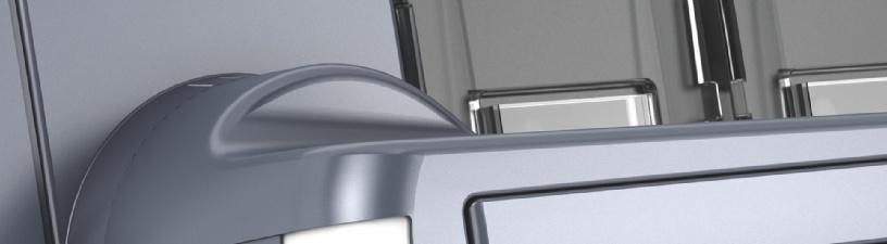
10 KD Switch Disconnectors up to 1600 A Introduction General data 1 Application KD switch disconnectors are designed for applications with exacting requirements. They are deployed as main control, EMERGENCY-STOP and maintenance switches in industrial plants, infrastructure and buildings. KD switch disconnectors are designed to switch the specified rated current on and off under load. At the same time, they constitute a safety isolating function and isolating distance in all low-voltage circuits. All KD switch disconnectors are climate-proof and meet the requirements of IEC , IEC and VDE Features -pole and 4-pole versions in 5 different sizes Supplied as a complete assembly including direct operating mechanism or as a basic unit without handle Direct operating mechanism with handle on switch disconnector Door-coupling rotary operating mechanism for operation of the switch disconnector outside the control cabinet door Versions with side operating mechanisms Connections in the form of box terminals or flat terminals Floor mounting or mounting on a standard mounting rail (sizes 1 and ) Additional poles can be retrofitted: 4th contact element, N or N/PE terminals Auxiliary switch for querying the switch position Suitable for AC or DC applications Design A KD switch disconnector consists of an operating mechanism module, three or four switching poles and a handle to operate the switch disconnector. Handles The direct operating mechanism version of the handle is mounted directly on the switch disconnector. It can also be supplied in the form of a door-coupling rotary operating mechanism for actuation of the switch disconnector outside the control cabinet door. The handle is available in gray or colored red/yellow for use as an EMERGENCY-STOP switch. Commonly used switch disconnector variants comprising basic unit and handle are available as complete assemblies. I01_188 Benefits Enhanced touch protection Contact position is clearly visible Locking functions help to prevent unauthorized operation Enhanced protection against inter-phase arcing Compact design saves space Wide variety of applications thanks to a range of different operating mechanisms Supplementary functions can be retrofitted Various service positions are possible thanks to optimized heat dissipation Test function to ensure safe commissioning Comprehensive support through provision of CAx data Handle either as direct operating mechanism or door-coupling rotary operating mechanism Position of operating mechanism modules To allow optimum utilization of the available installation space, units with front operating mechanisms can be supplied with the operating mechanism module in various positions - mounted on the left-hand side of the KD switch disconnector or in the center between the switching poles. On units with side operating mechanisms, the operating mechanism module is positioned on the right-hand side of the KD switch disconnector. Front operating mechanism on side -pole Front operating mechanism in center Side operating mechanism 4-pole 1/ Siemens 01
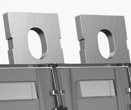
11 KD Switch Disconnectors up to 1600 A Introduction Additional poles All sizes of the KD switch disconnectors can be retrofitted with additional poles on a modular basis. When installing additional poles, it is important to note that only a -pole KD switch disconnector may be retrofitted with an additional switching pole with contact system (4th contact element). Additional poles (4th contact element, N or N/PE terminal) must always be mounted directly adjacent to the switch disconnector on the left or right, i.e. with sizes 1 and, therefore, it is not permissible to install an auxiliary switch module between the basic unit and an additional pole. General data Auxiliary switches Auxiliary switches allow remote interrogation of the contact position of the switch disconnector. Installation of auxiliary switches for sizes 1 and The auxiliary switches used for sizes 1 and are microswitches (changeover contacts) which can be snapped into an auxiliary switch module. This auxiliary switch module is mounted on the side of the switch disconnector in the same way as an additional pole. A maximum of two microswitches can be installed in each auxiliary switch module. 1 I01_1884 I01_1885 Installation of an additional pole Available versions: Fourth contact element: The 4th contact element includes a contact system and is identical to the poles installed at the factory. It can be installed to upgrade a -pole switch disconnector to a disconnector with 4 poles. Auxiliary switches with auxiliary switch module for sizes 1 and Installation of auxiliary switches for sizes to 5 With sizes to 5, the auxiliary switches are directly attached to the operating mechanism module. The auxiliary switch with the leading switch function is always installed in the right-hand mounting location. The other locations are provided for simultaneously switching with the main contacts. N N Fourth contact element as an additional pole N terminal (neutral conductor terminal): The N terminal does not include a contact system. A jumper can be removed in order to interrupt the electrical connection between the two terminals. An N terminal can be installed to add a non-switching N pole to a -pole disconnector. N N N terminal as non-switching pole N/PE terminal: The N/PE terminal is identical to the neutral conductor terminal. However, the electrical connection between the two terminals is permanent and cannot be interrupted by removal of a jumper. The N/PE terminal is normally deployed for applications in which it is vital to ensure that this connection can never be interrupted. 1 I01_18905 N N 1 N/PE terminal with permanent connections 1 1 Auxiliary switch, leading Auxiliary switch, simultaneous Auxiliary switches directly attached to the operating mechanism module with sizes to 5. The leading auxiliary switch is highlighted in the drawing. Siemens 01 1/
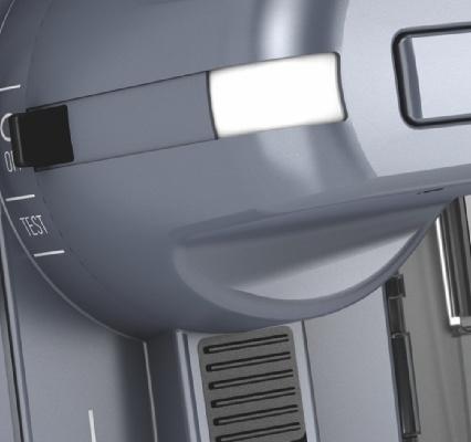
12 KD Switch Disconnectors up to 1600 A Introduction General data 1 Switching instants of auxiliary switches The auxiliary switches can operate either simultaneously with the main contacts or function as leading switches with all sizes. KD Main circuit Auxiliary switch standard Auxiliary switch leading On Off NO NC NO NC t I01_18906a Types of mounting All KD switch disconnectors are designed for floor mounting. To ensure that the switch can be flexibly adapted to the relevant installation conditions, the mounting bracket can be rotated through 90 with size or larger. I01_18918 One of the possible functions of leading auxiliary switches is to disconnect the circuit with the assistance of a higher-level switching device, such as a circuit breaker, before the main contacts of the KD switch disconnector open. With sizes 1 and, the selection of the appropriate auxiliary switch module determines whether the switching instant will be leading or simultaneous. With sizes, 4 and 5, the switching instant is determined by the selection of the mounting location for the auxiliary switch on the operating mechanism module. In this case, only SB auxiliary switches with NO contacts (1 or ) can be used as leading auxiliary switches. Test function for auxiliary switches The test function allows a wiring check to be performed on the auxiliary switches without necessitating closure of the main contacts of the KD switch disconnector. The test function can be used as part of the commissioning process. The test function is activated by turning the handle of a direct operating mechanism in the OFF position by 5 in the anti-clockwise direction. The handle must be turned 90 in the clockwise direction in order to switch the main contacts. Floor mounting method Sizes 1 and can be snapped onto a standard mounting rail (TH5 according to DIN EN 60715) as an alternative mounting method. Mounting on a standard mounting rail Locking functions KD switch disconnectors can be locked by up to three padlocks in order to prevent unauthorized switch operation. A flat version of the direct operating mechanisms is available for use in confined installation spaces. This can be secured with a lock without increasing the required mounting depth. The auxiliary switch module including test function must be used for sizes 1 and. With sizes, 4 and 5, all installed auxiliary switches are switched when the test function is activated. I01_1888 I01_1887 I01_1886 I01_1895 Locking functions involving one or more padlocks 1/4 Siemens 01
13 KD Switch Disconnectors up to 1600 A Introduction Electrical connection KD switch disconnectors are available with a number of different terminal types. Box terminals Box terminals for sizes 1 and (rated currents 16 A to 160 A) are designed to allow the speedy connection of stripped conductors. General data Terminal covers Terminal covers can be installed to provide touch protection for all terminals. 1 Connection via box terminals Flat terminals Sizes to 5 (rated currents 80 A to 1600 A) are available with flat terminals for the connection of cable lugs or busbar systems. I01_1889 Terminal covers Phase barriers When long, non-insulated cable lugs are used, phase barriers provide enhanced protection against arcing. I01_18910 I01_18909 Connection via flat terminals Terminal covers and phase barriers can be supplied for KD switch disconnectors with flat terminals. I01_18841 Phase barriers Siemens 01 1/5


14 KD Switch Disconnectors up to 1600 A Introduction 1 Overview Technical features LD main control and EMERGENCY-STOP switches KD switch disconnectors: Box terminals KD switch disconnectors: Flat terminals Size 1 Type LD 0 LD 1 LD LD 5 KD...-.M LD 7 LD 8 LD KD...-.N LD main control and EMERGENCY-STOP switches KD switch disconnectors LD main control and EMERGENCY- STOP switches KD switch disconnectors Rated current I n A Number of poles 4 Connections Flat terminals Box terminals -- Operating mechanism Front operating mechanism Side operating mechanisms Operating and short-circuit behavior Rated short-time withstand current I cw (1 s current, rms value) ka Rated conditional short-circuit ka rms current with upstream fuses at 690 V 1) 1) Valid for the combination of KD switch disconnector and fuse type NA, characteristic gg Available -- Not available For further information about LD main control and EMERGENCY-STOP switches, see Catalog LV 10, Chapter 7 Industry Mall, section "Building Technologies" --> "Low-Voltage Controls and Distribution" --> "SENTRON protection, switching, measuring and monitoring devices" --> "Switching devices" --> "Switch disconnectors" --> "LD main and EMERGENCY-STOP switches up to 50 A" 1/6 Siemens 01


15 Overview (continued) LD main control and EMERGENCY-STOP switches Siemens AG 01 KD Switch Disconnectors up to 1600 A Introduction Technical features 1 KD switch disconnectors: Box terminals KD switch disconnectors: Flat terminals Size 4 5 Type LD4 KD...-.P KD...-.Q KD...-.R LD main control and EMERGENCY- STOP switches KD switch disconnectors Rated current I n A Number of poles 4 Connections Flat terminals -- Box terminals Operating mechanism Front operating mechanism Side operating mechanisms -- Operating and short-circuit behavior Rated short-time withstand current I cw (1 s current, rms value) ka Rated conditional short-circuit current with upstream fuses at 690 V 1) ka rms ) Valid for the combination of KD switch disconnector and fuse type NA, characteristic gg Available -- Not available For further information about LD main control and EMERGENCY-STOP switches, see Catalog LV 10, Chapter 7 Industry Mall, page "Building Technologies" --> "Low-Voltage Controls and Distribution" --> "SENTRON protection, switching, measuring and monitoring devices" --> "Switching devices" --> "Switch disconnectors" --> "LD main and EMERGENCY-STOP switches up to 50 A" Siemens 01 1/7
 Direct operating mechanism (suitable for distribution boards) Door-coupling rotary operating mechanism Phase barriers Cable")
16 KD Switch Disconnectors up to 1600 A Introduction Technical features 1 Overview of components and accessories: Sizes 1 and of KD switch disconnectors I01_ KD switch disconnectors Direct operating mechanism (standard version) Direct operating mechanism (suitable for distribution boards) Door-coupling rotary operating mechanism Phase barriers Cable connection cover, short Cable connection covers 7 8 N/PE terminal (with permanent jumper) 9 Neutral conductor terminal (with removable jumper) 10 Mounting bracket (spare part) 11 4th contact element 1 Auxiliary switch module 1 Auxiliary switch 1/8 Siemens 01
 8 Neutral")
17 KD Switch Disconnectors up to 1600 A Introduction Overview of components and accessories: Sizes to 5 of KD switch disconnectors Technical features I01_ KD switch disconnectors Direct operating mechanism Door-coupling rotary operating mechanism Phase barriers Cable connection cover, short Cable connection cover 7 N/PE terminal (with permanent jumper) 8 Neutral conductor terminal (with removable jumper) 9 4th contact element 10 Auxiliary switch 6 Siemens 01 1/9
18 KD Switch Disconnectors up to 1600 A Introduction Technical features 1 Technical specifications Sizes 1 and Standards IEC , IEC Type KD16 KD KD6 KD8 KD0 KD KD4 KD6...N Size General technical details Rated uninterrupted current I u A Continuous free-air thermal current I 1) th A Rated operational voltage U e At 50/60 Hz AC V 690 At DC - conducting paths series-connected V 0 At DC - conducting paths series-connected V 440 Rated insulation voltage U i V 1000 Rated impulse withstand voltage U imp kv Overvoltage category III III III III III III III III Pollution degree Operating and short-circuit behavior Rated operational current I e At AC-1A, AC-A, 400 to 690 V A At AC-, 400V A At AC-, 500V A At AC-, 690 V A At DC-1A, 0/440 V A At DC-A, 0/440 V A At DC-A, 0/440 V A Motor switching capacity AC-A ) At 400 V kw At 500 V kw At 690 V kw Rated short-time withstand current I cw (with t = 1 s, rms value, 690 V AC / 440 V DC) ka Rated short-circuit making capacity I cm (at 690 V AC / 440 V DC) ka Rated current of upstream fuse ) A Rated conditional short-circuit current with upstream fuse ) At 400/500 V AC ka At 690 V AC ka Let-through current combined with upstream fuse ) At 400/500 V AC ka At 690 V AC ka Let-through I t value combined with upstream fuse ) At 400/500 V ka s At 690 V ka s Power loss per pole with thermal current I th W Service life, operating cycles Mechanical Electrical, at AC-A, 690 V/ Hz Electrical, at DC-A, 0/440 V Degree of protection With masking plate or cable connection cover IP0 IP0 IP0 IP0 IP0 IP0 IP0 IP0 Without masking plate or terminal cover IP0 IP0 IP0 IP00 4) /IP0 IP00 Ambient conditions Ambient temperature during operation C (no derating of Ith at -5 to +55 C) Ambient temperature during storage C Mounting position 5) Any Main conductor connections Conductor cross-section, max. mm (95) 6) 70 (95) 6) 70 (95) 6) 70 (95) 6) 95 Busbar systems, max. dimensions (number x width x thickness) Flat terminals mm -- 1 x 0 x 7) Box terminals mm 1 x 9 x 1 x 14 x Tightening torque Flat terminals Nm Box terminals Nm ) Configuring note: Max. permissible operating temperature at connections 15 C ) These values are provided as a guide only and may vary depending on the make of motor ) Valid for the combination of KD and fuse type NA8 for I u = A; NA1 for I u = 00 A; characteristic gg 4) Relevant only for devices with flat terminals 5) With mounting positions other than the vertical, please contact Technical Support 6) 95 mm² valid for variants with flat terminals 7) If 0-mm-wide busbars are used, insulated busbars are necessary. 1/10 Siemens 01
19 Technical specifications (continued) Sizes to 5 Siemens AG 01 KD Switch Disconnectors up to 1600 A Introduction Technical features 1 Standards IEC , IEC Type KD6..-.P KD8 KD40 KD4 KD44 KD46 KD48 KD50 KD5 KD54 Size General technical details Rated uninterrupted current I u A Continuous free-air thermal current I 1) th A Rated operational voltage U e At 50/60 Hz AC V 690 At DC - conducting paths series-connected V 0 At DC - conducting paths series-connected V 440 Rated insulation voltage U i V 1000 Rated impulse withstand voltage U imp kv Overvoltage category IV IV IV IV IV IV IV IV IV IV Pollution degree Operating and short-circuit behavior ) ) Rated operational current I e At AC-1A, AC-A, 400 to 690 V A At AC-, 400V A At AC-, 500V A At AC-, 690 V A At DC-1A, 0/440 V A At DC-A, 0/440 V A At DC-A, 0/440 V A Motor switching capacity AC-A 4) At 400 V kw At 500 V kw At 690 V kw Rated short-time withstand current I cw (with t = 1 s, rms value, 690 V AC / 440 V DC) ka Rated short-circuit making capacity I cm (at 690 V AC / 440 V DC) ka Rated current of upstream fuse 5) A Rated conditional short-circuit current with upstream fuse 5) At 400/500 V AC ka At 690 V AC ka Let-through current combined with upstream fuse 5) At 400/500 V AC ka At 690 V AC ka Let-through I t value combined with upstream fuse 5) At 400/500 V ka²s At 690 V ka²s Power loss per pole with thermal current I th W Service life, operating cycles Mechanical Electrical, at AC-A, 690 V/ Hz Electrical, at DC-A, 0/440 V Degree of protection With masking plate or cable connection cover IP0 IP0 IP0 IP0 IP0 IP0 IP0 IP0 IP0 IP0 Without masking plate or terminal cover IP00 IP00 IP00 IP00 IP00 IP00 IP00 IP00 IP00 IP00 Ambient conditions Ambient temperature during operation C (no derating of I th at -5 to +55 C) Ambient temperature during storage C Mounting position 6) Any Main conductor connections Conductor cross-section, max. mm 40 x 40 x 40 Busbar systems, max. dimensions (number x width x thickness) Flat terminals mm 1 x 0 x 10 x 40 x 5 x 60 x 10 Box terminals mm 1 x 0 x 10 x 40 x 5 x 60 x 10 Tightening torque Flat terminals Nm Box terminals Nm ) Configuring note: Max. permissible operating temperature at connections 15 C ) With size switch disconnectors, phase barriers or terminal covers (accessories) are required for: - Busbar systems at AC-1A, AC-A and U e >400 V, AC-A and - when cable lugs are connected ) With size 4 at AC-A, phase barriers or terminal covers must be installed (accessories) 4) These values are provided as a guide only and may vary depending on the make of motor 5) Valid for the combination of KD and fuse type NA, characteristic gg 6) With mounting positions other than the vertical, please contact Technical Support Siemens 01 1/11
20 KD Switch Disconnectors up to 1600 A Introduction 1 Notes 1/1 Siemens 01

21 KD Switch Disconnectors up to 1600 A KD Switch Disconnectors up to 1600 A / Introduction / Complete assemblies /4 Basic units /6 Accessories and spare parts /1 Dimensions and typical circuit diagrams Siemens 01

22 KD Switch Disconnectors up to 1600 A Introduction Overview Devices Description Page Complete assemblies Complete assemblies with direct operating mechanisms Ready-to-install combinations comprising switch disconnectors and operating mechanisms - and 4-pole switch disconnectors with front operating mechanisms Connections in form of box terminal or flat terminal incl. direct operating mechanism with gray handle Basic units Front operating mechanisms Switch disconnectors with front operating mechanisms without handle - and 4-pole versions Connections in form of box terminal or flat terminal Operating mechanism module in center or on left-hand side of switch disconnector 4 Side operating mechanisms Switch disconnectors with side operating mechanisms - and 4-pole versions Connections in form of box terminal or flat terminal Operating mechanism module on right-hand side of switch disconnector 5 Accessories and spare parts Additional poles Additional poles for enhanced functionality 4thcontact element (switching pole) N terminal (neutral conductor terminal with removable jumper) N/PE terminal (with permanent jumper) 6 Additional poles: Left: Box terminal Right: Flat terminal Direct operating mechanisms Different handles for mounting on basic units Direct operating mechanisms for direct mounting on switch disconnector Handles available in colors gray or red/yellow 7 Door-coupling rotary operating mechanisms Different handles for mounting on basic units Door-coupling rotary operating mechanisms for operation of switch disconnector outside the control cabinet door Handles available in colors gray or red/yellow 7 Auxiliary switches Auxiliary switches For querying the switch position Optionally available with leading NO contacts (auxiliary switch contacts open before the main contacts of the KD switch disconnector) Optionally available with test function (switch can be tested without closure of main contacts) 9 Other accessories Terminal covers Phase barriers Cable connection cover as touch protection for termination area (for installation outside control cabinet) Mounting bracket for wall mounting (spare part) 10 Left: Cable connection cover Right: Phase barrier / Siemens 01


23 KD Switch Disconnectors up to 1600 A Complete assemblies Selection and ordering data Rated uninterrupted current I u Size DT Article No. Price per PU A Complete assemblies with direct operating mechanism gray, front operating mechanism The switch disconnectors are designed for floor mounting; sizes 1 and can optionally be mounted on standard mounting rails -pole Flat terminal 1) PU (UNIT, SET, M) PS*/ P. unit PG Weight per PU approx. kg 80 KD8-0NE unit KD0-0NE unit KD-0NE unit KD4-0NE unit KD6-0NE unit pole, flat terminal, size KD6-0PE10-0 KD8-0PE unit 1 unit KD40-0PE unit KD4-0PE unit KD44-0QE unit KD46-0QE unit KD48-0QE unit pole, flat terminal, size KD50-0RE unit KD5-0RE unit KD54-0RE unit Box terminal 16 1 KD16-ME unit KD-ME unit KD6-ME unit KD8-NE unit KD0-NE unit KD-NE unit pole, box terminal, size 160 KD4-NE unit pole Flat terminal 1) 80 KD84-0NE unit KD04-0NE unit KD4-0NE unit KD44-0NE unit KD64-0NE unit pole, flat terminal, size KD64-0PE10-0 KD84-0PE10-0 KD404-0PE unit 1 unit 1 unit KD44-0PE unit KD444-0QE unit KD464-0QE unit KD484-0QE unit pole, flat terminal, size KD504-0RE10-0 KD54-0RE unit 1 unit KD544-0RE unit Box terminal 16 1 KD164-ME unit KD4-ME unit KD64-ME unit KD84-NE unit KD04-NE unit KD4-NE unit pole, box terminal, size 160 KD44-NE unit ) Cable connection covers must be provided for switch disconnectors with flat terminals and direct operating mechanisms * You can order this quantity or a multiple thereof. Siemens 01 /

 80 KD80-0NE10-0 KD80-0NE0-0 1 1 unit 14 0.80 100 KD00-0NE10-0 KD00-0NE0-0 1 1 unit 14 0.80 15 KD0-0NE10-0 KD0-0NE0-0 1 1 unit 14 0.")

24 KD Switch Disconnectors up to 1600 A Basic units Rated uninterrupted current I u A Basic units without handle, front operating mechanisms The switch disconnectors are designed for floor mounting; sizes 1 and can optionally be mounted on DIN rails -pole Operating mechanism on left Operating mechanism in center Size DT Article No. Price DT Article No. per PU Price per PU PU (UNIT, SET, M) PS*/ P. unit PG Weight per PU approx. kg -pole, flat terminal, size, operating mech. on left -pole, flat terminal, size 5, operat. mech. in center -pole, box terminal, size, operat. mech. on left Flat terminal 1) 80 KD80-0NE10-0 KD80-0NE unit KD00-0NE10-0 KD00-0NE unit KD0-0NE10-0 KD0-0NE unit KD40-0NE10-0 KD40-0NE unit KD60-0NE10-0 KD60-0NE unit KD60-0PE10-0 KD60-0PE unit KD80-0PE10-0 KD80-0PE unit KD400-0PE10-0 KD400-0PE unit KD40-0PE10-0 KD40-0PE unit KD440-0QE10-0 KD440-0QE unit KD460-0QE10-0 KD460-0QE unit KD480-0QE10-0 KD480-0QE unit KD500-0RE10-0 KD500-0RE unit KD50-0RE10-0 KD50-0RE unit KD540-0RE10-0 KD540-0RE unit Box terminal 16 1 KD160-ME10-0 KD160-ME unit KD0-ME10-0 KD0-ME unit KD60-ME10-0 KD60-ME unit KD80-NE10-0 KD80-NE unit KD00-NE10-0 KD00-NE unit KD0-NE10-0 KD0-NE unit KD40-NE10-0 KD40-NE unit pole 4-pole, flat termin., size, operat. mechanism on left 4-pole, flat terminal, size 5, operat. mech. in center 4-pole, box termin., size, operat. mechanism on left Flat terminal 1) 80 KD840-0NE10-0 KD840-0NE unit KD040-0NE10-0 KD040-0NE unit KD40-0NE10-0 KD40-0NE unit KD440-0NE10-0 KD440-0NE unit KD640-0NE10-0 KD640-0NE unit KD640-0PE10-0 KD640-0PE unit KD840-0PE10-0 KD840-0PE unit KD4040-0PE10-0 KD4040-0PE unit KD440-0PE10-0 KD440-0PE unit KD4440-0QE10-0 KD4440-0QE unit KD4640-0QE10-0 KD4640-0QE unit KD4840-0QE10-0 KD4840-0QE unit KD5040-0RE10-0 KD5040-0RE unit KD540-0RE10-0 KD540-0RE unit KD5440-0RE10-0 KD5440-0RE unit Box terminal 16 1 KD1640-ME10-0 KD1640-ME unit KD40-ME10-0 KD40-ME unit KD640-ME10-0 KD640-ME unit KD840-NE10-0 KD840-NE unit KD040-NE10-0 KD040-NE unit KD40-NE10-0 KD40-NE unit KD440-NE10-0 KD440-NE unit ) Phase barriers for size included in scope of supply /4 Siemens 01 * You can order this quantity or a multiple thereof.
 PS*/ P. unit PG Weight per PU approx. kg Flat terminal 00 KD64-0PE40-0 1 1 unit 14.")
25 KD Switch Disconnectors up to 1600 A Basic units Rated uninterrupted current I u Size DT Article No. Price per PU A Basic units without handle, side operating mechanisms -pole PU (UNIT, SET, M) PS*/ P. unit PG Weight per PU approx. kg Flat terminal 00 KD64-0PE unit KD84-0PE unit KD404-0PE unit KD44-0PE unit pole, flat terminal, size KD444-0QE unit KD464-0QE unit KD484-0QE unit KD504-0RE unit KD54-0RE unit KD544-0RE unit pole Flat terminal 00 KD644-0PE unit KD844-0PE unit KD4044-0PE unit pole, flat terminal, size 400 KD444-0PE unit KD4444-0QE unit KD4644-0QE unit KD4844-0QE unit KD5044-0RE unit KD544-0RE unit KD5444-0RE unit * You can order this quantity or a multiple thereof. Siemens 01 /5
26 KD Switch Disconnectors up to 1600 A Accessories and spare parts Selection and ordering data Additional poles Type Circuit symbol DT Article No. Price per PU 4thcontact element (switching pole) mm N N PU (UNIT, SET, M) PS*/ P. unit PG Weight per PU approx. Flat terminal for size ; KD...-.N -- KD unit for size ; KD...-.P KD unit for size 4; KD...-.Q KD unit for size 5; KD...-.R KD unit kg 4thcontact element, flat terminal, for size Box terminal for size 1; KD...-.M KD unit for size ; KD...-.N KD unit thcontact element, box terminal, for size Neutral conductor terminal with removable jumper Flat terminal for size ; KD...-.N KD unit for size ; KD...-.P KD unit for size 4; KD...-.Q KD unit for size 5; KD...-.R KD unit Neutral conductor terminal, flat terminal, for size Box terminal for size 1; KD...-.M KD unit for size ; KD...-.N KD unit Neutral conductor terminal, box terminal, for size N/PE terminal with permanent jumper Flat terminal for size ; KD...-.N KD unit for size ; KD...-.P KD unit for size 4; KD...-.Q KD unit for size 5; KD...-.R KD unit N/PE terminal, flat terminal, for size Box terminal for size 1; KD...-.M KD unit for size ; KD...-.N KD unit N/PE terminal, box terminal, for size /6 Siemens 01 * You can order this quantity or a multiple thereof.

27 KD Switch Disconnectors up to 1600 A Accessories and spare parts Operating mechanisms Type Shaft size handle end 1) Shaft size DT Article No. Price 1) switch end per PU PU (UNIT, SET, M) PS*/ P. unit PG Weight per PU approx. mm x mm mm x mm kg Direct operating mechanisms Standard version Can be locked with up to max. padlocks, requires additional mounting depth in locked state Gray for size 1; KD...-.M KD unit for size ; KD...-.N KD unit for size ; KD...-.P KD unit for size 4; KD...-.Q KD unit Direct operating mechanism, gray, for size 5; KD...-.R for size KD unit Red/yellow for size 1; KD...-.M KD unit for size ; KD...-.N KD unit for size ; KD...-.P KD unit for size 4; KD...-.Q KD unit Direct operating mechanism, for size 5; KD...-.R KD unit red/yellow, for size Flat version (suitable for distribution boards) Can be locked with one padlock, requires no additional mounting depth in locked state Gray for size 1; KD...-.M KD unit for size ; KD...-.N KD unit Direct operating mechanism, flat version, gray, for size Red/yellow for size 1; KD...-.M KD unit for size ; KD...-.N KD unit Door-coupling rotary operating mechanisms Door-coupling rotary operating mechanism incl. 00 mm extension shaft and coupling driver Gray for size 1; KD...-.M 8 x 8 8 x 8 KD unit for size ; KD...-.N 8 x 8 8 x 8 KD unit for size ; KD...-.P 10 x 10 8 x 8 KD unit for size 4; KD...-.Q 10 x x 10 KD unit Door-coupling rotary operating mechanism, gray, for size 1 Door-coupling rotary operating mechanism, red/yellow, for size 1 for size 5; KD...-.R 1 x 1 1 x 1 KD unit Red/yellow for size 1; KD...-.M 8 x 8 8 x 8 KD unit for size ; KD...-.N 8 x 8 8 x 8 KD unit for size ; KD...-.P 10 x 10 8 x 8 KD unit for size 4; KD...-.Q 10 x x 10 KD unit for size 5; KD...-.R 1 x 1 1 x 1 KD unit * You can order this quantity or a multiple thereof. Siemens 01 /7
 per PU PU (UNIT, SET, M) PS*/ P. unit mm x mm mm x mm kg Handles without extension shaft and coupling driver Gray for size 1; KD...-.")
28 KD Switch Disconnectors up to 1600 A Accessories and spare parts Handle without extension shaft, gray, for size 1 Handle without extension shaft, gray, for size 1 Type Shaft size handle end 1) Shaft size DT Article No. Price switch end1) per PU PU (UNIT, SET, M) PS*/ P. unit mm x mm mm x mm kg Handles without extension shaft and coupling driver Gray for size 1; KD...-.M 8 x 8 -- KD unit for size ; KD...-.N 8 x 8 -- KD unit for size ; KD...-.P 10 x KD unit for size 4; KD...-.Q 10 x KD unit for size 5; KD...-.R 1 x 1 -- KD unit Red/yellow for size 1; KD...-.M 8 x 8 -- KD unit for size ; KD...-.N 8 x 8 -- KD unit for size ; KD...-.P 10 x KD unit for size 4; KD...-.Q 10 x KD unit for size 5; KD...-.R 1 x 1 -- KD unit Extension shafts 00 mm long for size 1/ 8 x 8 8 x 8 8UC unit for size ; KD...-.P 10 x 10 8 x 8 KD unit for size 4; KD...-.Q 10 x x 10 8UC unit for size 5; KD...-.R 1 x 1 1 x 1 8UC unit PG Weight per PU approx. Extension shaft, 00 mm long, for size 600 mm long for size 1/ 8 x 8 8 x 8 8UC unit for size ; KD...-.P 10 x 10 8 x 8 KD unit for size 4; KD...-.Q 10 x x 10 8UC unit for size 5; KD...-.R 1 x 1 1 x 1 8UC unit Extension shaft, 600 mm long, for size 8UC601 coupling driver Lug Shaft coupling Rivet NSE0_0074 Rivet NSE0_007 Coupling drivers for 8 x 8 mm shafts 8UC6017-AA 1 1 unit for 10 x 10 mm shafts 8UC unit for 1 x 1 mm shafts 8UC unit Shaft couplings for 8 x 8 mm shafts 8UC unit for 10 x 10 mm shafts 8UC unit for 1 x 1 mm shafts 8UC unit ) With different shaft sizes at the handle/at the switch, the shaft cross-section changes over the length of the shaft /8 Siemens 01 * You can order this quantity or a multiple thereof.
29 KD Switch Disconnectors up to 1600 A Accessories and spare parts Auxiliary switches Type DT Article No. Price per PU PU (UNIT, SET, M) PS*/ P. unit PG Weight per PU approx. kg Auxiliary switch modules for sizes 1 and 1) Standard version KD unit Version with test function KD unit Version with leading NO contacts + test function KD unit Auxiliary switch module, standard version Auxiliary switches for sizes 1 and ) 1 CO KD unit Auxiliary switch 1 CO contact, solid-state compatible 1 CO contact, solid-state compatible KD unit Auxiliary switch SB400-0B for sizes to 5 ) 1 NO } SB400-0B 1 1 unit 41J NO with gold-plated contacts SB400-0BA 1 1 unit 41J NC } SB400-0C 1 1 unit 41J NO with gold-plated contacts SB400-0CA 1 1 unit 41J NO + 1 NC } SB400-0A 1 1 unit 41J NO + 1 NC with gold-plated contacts SB400-0AA 1 1 unit 41J NO SB400-0D 1 1 unit 41J NO with gold-plated contacts SB400-0DA 1 1 unit 41J NC SB400-0E 1 1 unit 41J NC with gold-plated contacts SB400-0EA 1 1 unit 41J Auxiliary switch SB400-0A 1) Unit is supplied without auxiliary switches, a maximum of auxiliary switches can be installed ) Unit is shipped with soldered-on 50 cm connecting cables ) Auxiliary switch with screw-type terminal for installation on operating mechanism module. Auxiliary switches with spring-type terminal SB40-.. from the SB program can also be used * You can order this quantity or a multiple thereof. Siemens 01 /9
30 KD Switch Disconnectors up to 1600 A Accessories and spare parts Other accessories Phase barriers Type For size DT Article No. Price per PU PU (UNIT, SET, M) PS*/ P. unit PG Weight per PU approx. For KD with flat terminal For -pole devices (1 set = 6 units) ; KD...-.N KD unit ; KD...-.P KD unit ; KD...-.Q KD unit ; KD...-.R KD unit For 4-pole devices (1 set = 8 units) ; KD...-.N KD unit ; KD...-.P KD unit Phase barrier for size 4; KD...-.Q KD unit devices with or 4 poles 5; KD...-.R KD unit Cable connection covers For KD with flat terminal For -pole devices (1 set = 6 units) Standard length ; KD...-.N KD unit ; KD...-.P KD unit ; KD...-.Q KD unit ; KD...-.R KD unit kg Cable connection cover, standard length, for size devices with poles Short version ; KD...-.N KD unit ; KD...-.P KD unit ; KD...-.Q KD unit Cable connection cover, short version, for size devices with poles For 4-pole devices (1 set = 8 units) Standard length ; KD...-.N KD unit ; KD...-.P KD unit ; KD...-.Q KD unit ; KD...-.R KD unit Cable connection cover, standard length, for size devices with 4 poles Short version ; KD...-.N KD unit ; KD...-.P KD unit ; KD...-.Q KD unit Cable connection cover, short version, for size devices with 4 poles /10 Siemens 01 * You can order this quantity or a multiple thereof.

31 KD Switch Disconnectors up to 1600 A Accessories and spare parts Type For size DT Article No. Price per PU PU (UNIT, SET, M) kg Spare cable connection cover (1 unit) Standard length 5; KD...-.R KD unit Short version ; KD...-.N KD unit ; KD...-.P KD unit ; KD...-.Q KD unit Mounting bracket (1 set = 4 units) Spare part, is included in the scope of supply of the KD. Mounting bracket 1 and KD unit PS*/ P. unit PG Weight per PU approx. * You can order this quantity or a multiple thereof. Siemens 01 /11
32 KD Switch Disconnectors up to 1600 A Dimensions and typical circuit diagrams Dimensional drawings Size 1 Ø R I01_ Complete assembly with direct operating mechanism, -pole, box terminal Ø 4,5 18 Installation depth of extension shaft ,6 9, ,4 I01_ , Basic unit without handle, -pole, box terminal /1 Siemens 01
33 KD Switch Disconnectors up to 1600 A Dimensions and typical circuit diagrams Size 1 (continued) Ø R I01_ Complete assembly with direct operating mechanism, 4-pole, box terminal Ø 4, Installation depth of extension shaft 46, ,6 9,6 8 I01_ ,4 Basic unit without handle, 4-pole, box terminal Siemens 01 /1
34 KD Switch Disconnectors up to 1600 A Dimensions and typical circuit diagrams Size 1 (continued) Optional mounting position Optional mounting position I01_ I01_ Accessories: 4th contact element, neutral conductor terminal, N/PE terminal Note: 4th contact element can only be installed on -pole basic units; for side view dimensions, see basic unit Accessories: Auxiliary switch module Note: Auxiliary switch modules with test function must always be installed directly adjacent to the operating mechanism unit Extension shaft 78 Extension shaft I01_18746 I01_ Accessories: Direct operating mechanism, standard version Accessories: Direct operating mechanism, flat version I01_ Accessories: Handle of door-coupling rotary operating mechanism /14 Siemens 01
35 KD Switch Disconnectors up to 1600 A Dimensions and typical circuit diagrams Size Ø R I01_ Complete assembly with direct operating mechanism, -pole, box terminal Ø 4, Installation depth of extension shaft 4 46, ,6 1,4 I01_ ,8 Basic unit without handle, -pole, box terminal Ø 9 Ø 4.5 R I01_ Complete assembly with direct operating mechanism, -pole, flat terminal Siemens 01 /15
36 KD Switch Disconnectors up to 1600 A Dimensions and typical circuit diagrams Size (continued) 7 Installation depth 8, of extension shaft 0 Ø 9 Ø 4,5 4 46, , I01_1867 Basic unit without handle, -pole, flat terminal Ø R I01_ Complete assembly with direct operating mechanism, 4-pole, box terminal 7 Installation depth of extension shaft Ø 4,5 4 46, , ,4 15,8 I01_18694 Basic unit without handle, 4-pole, box terminal /16 Siemens 01
37 KD Switch Disconnectors up to 1600 A Dimensions and typical circuit diagrams Size (continued) Ø 9 Ø R I01_18666 Complete assembly with direct operating mechanism, 4-pole, flat terminal 7 8, Installation depth of extension shaft Ø 4,5 0 Ø 9 46, ,6 Basic unit without handle, 4-pole, flat terminal Optional mounting position Optional mounting position I01_ I01_1870 Accessories: 4th contact element, neutral conductor terminal, N/PE terminal with box terminal Note: 4th contact element can only be installed on -pole basic units; for side view dimensions, see basic unit Accessories: 4th contact element, neutral conductor terminal, N/PE terminal with flat terminal Notes: 4th contact element can only be installed on -pole basic units; for side view dimensions, see basic unit Siemens 01 /17
38 KD Switch Disconnectors up to 1600 A Dimensions and typical circuit diagrams Size (continued) Optional mounting position Optional mounting position I01_ I01_ Accessories: Auxiliary switch module, installed on KD switch disconnector with box terminal Note: Auxiliary switch modules with test function must always be installed directly adjacent to the operating mechanism unit Accessories: Auxiliary switch module, installed on KD with flat terminal Note: Auxiliary switch modules with test function must always be installed directly adjacent to the operating mechanism unit I01_18708 I01_ Accessories: Direct operating mechanism, standard version Accessories: Direct operating mechanism, flat version /18 Siemens 01
39 KD Switch Disconnectors up to 1600 A Dimensions and typical circuit diagrams Size (continued) I01_ Accessories: Handle of door-coupling rotary operating mechanism Accessories: Cable connection covers, standard version 71 I01_ I01_ I01_ Accessories: Phase barriers Accessories: Cable connection covers, short version Siemens 01 /19
40 KD Switch Disconnectors up to 1600 A Dimensions and typical circuit diagrams Size 44 0 Ø Dimension Ø4, Auxiliary switch type A B C SB400-0B, , 47 SB400-0D, 19, SB400-0C, , A 4 6 SB400-0E, SB400-0A, 19 19,, I01_18661 Auxiliary switches see table R9, C B 85,5 10,5 Complete assembly with direct operating mechanism, -pole, flat terminal 44 0 Ø11 40 Dimension Ø4, A Auxiliary switch type SB400-0B, SB400-0D, SB400-0C, SB400-0E, A B C ,, 6,, SB400-0A, 19, Auxiliary switches see table C B 85,5 9, Installation depth of extension shaft I01_18674 Basic unit without handle, -pole, flat terminal Ø4, Ø Auxiliary switch type SB400-0B, SB400-0D, SB400-0C, Dimension A B C ,, 7 6, A SB400-0E, 19, 4 6 SB400-0A, 19, I01_18667 R9,8 Auxiliary switches see table C B 85,5 10,5 Complete assembly with direct operating mechanism, 4-pole, flat terminal /0 Siemens 01
41 KD Switch Disconnectors up to 1600 A Dimensions and typical circuit diagrams Size (continued) 44 0 Ø11 40 Ø4, Auxiliary switch type SB400-0B, SB400-0D, SB400-0C, Dimension A B C ,, 7 6, A 4 6 SB400-0E, SB400-0A, 19 19,, I01_18686 Auxiliary switches see table C B 85,5 10, Installation depth of extension shaft Basic unit without handle, front operating mechanism, 4-pole, flat terminal 40 Ø Ø4, Auxiliary switch type SB400-0B, SB400-0D, SB400-0C, Dimension A B C ,, 7 6, 4 8 A SB400-0E, SB400-0A, 19 19,, I01_ ,5 B C 85, Auxiliary switches see table Installation depth of extension shaft Basic unit without handle, side operating mechanism, -pole, flat terminal Ø Ø4, Auxiliary switch type SB400-0B, SB400-0D, SB400-0C, SB400-0E, Dimension A B C ,, 7 6,, 4 8 A SB400-0A, 19, I01_ ,5 B C 85, Auxiliary switches see table Installation depth of extension shaft Basic unit without handle, side operating mechanism, 4-pole, flat terminal Siemens 01 /1
42 KD Switch Disconnectors up to 1600 A Dimensions and typical circuit diagrams Size (continued) Optional mounting position 44 I01_1874 Accessories: 4th contact element, neutral conductor terminal, N/PE terminal with flat terminal Notes: 4th contact element can only be installed on -pole basic units; for side view dimensions, see basic unit ,5 Extension shaft , I01_ ,5 Accessories: Direct operating mechanism, standard version I01_18757 Accessories: Handle of door-coupling rotary operating mechanism / Siemens 01
43 KD Switch Disconnectors up to 1600 A Dimensions and typical circuit diagrams Size (continued) ,5 68 Accessories: Phase barriers ,5 I01_ I01_ I01_ Accessories: Cable connection covers, standard version Accessories: Cable connection covers, short version Siemens 01 /
44 KD Switch Disconnectors up to 1600 A Dimensions and typical circuit diagrams Size Ø14 46,5 Dimension Ø6,6 A 67, Auxiliary switch type SB400-0B, SB400-0D, SB400-0C, A B C ,15, ,15 Auxiliary switches see table R C B 101,5 166,5 SB400-0E, SB400-0A, ,15,15 I01_1866 Complete assembly with direct operating mechanism, -pole, flat terminal Ø6,6 A 67, Ø ,5 Auxiliary switch type SB400-0B, SB400-0D, SB400-0C, SB400-0E, Dimension A B C ,15, ,15,15 Auxiliary switches see table C B 101,5 110 SB400-0A, Installation depth 60 0 of extension shaft ,15 I01_18676 Basic unit without handle, front operating mechanism, -pole, flat terminal Ø14 46,5 Ø6,6 A Auxiliary switch type SB400-0B, SB400-0D, SB400-0C, SB400-0E, Dimension A B C ,15, ,15,15 8 SB400-0A, 184,15 I01_18668 R140 Auxiliary switches see table C B 101,5 166,5 Complete assembly with direct operating mechanism, 4-pole, flat terminal /4 Siemens 01
45 KD Switch Disconnectors up to 1600 A Dimensions and typical circuit diagrams Size 4 (continued) Ø6,6 67, Ø ,5 Auxiliary switch type SB400-0B, SB400-0D, SB400-0C, Dimension A B C ,15, ,15 A Auxiliary switches see table C B 101,5 110 SB400-0E, SB400-0A, Installation depth 60 0 of extension shaft ,15,15 I01_18688 Basic unit without handle, front operating mechanism, 4-pole, flat terminal 46,5 Ø Dimension 4 Ø6,6 Auxiliary switch type SB400-0B, A B C ,15 106, ,5 11 A SB400-0D, SB400-0C, SB400-0E, SB400-0A, ,15 49,15,15,15 I01_ B C 101,5 111,5 4 Auxiliary switches see table Installation depth 0 of extension shaft -10 Basic unit without handle, side operating mechanism, -pole, flat terminal 46,5 4 Ø Dimension Ø6,6 Auxiliary switch type A B C SB400-0B, ,15 106, ,5 11 A SB400-0D, SB400-0C, SB400-0E, SB400-0A, ,15 49,15,15,15 I01_18700 B C 101,5 111,5 8 Auxiliary switches see table Installation depth 0 of extension shaft -10 Basic unit without handle, side operating mechanism, 4-pole, flat terminal Siemens 01 /5
46 KD Switch Disconnectors up to 1600 A Dimensions and typical circuit diagrams Size 4 (continued) Optional mounting position I01_ I01_18758 Accessories: 4th contact element, neutral conductor terminal, N/PE terminal with flat terminal Note: 4th contact element can only be installed on -pole basic units; for side view dimensions, see basic unit Accessories: Handle of door-coupling rotary operating mechanism 171,5 140±0, Extension shaft , ,5 Accessories: Direct operating mechanism, standard version 1 I01_ I01_ Accessories: Phase barriers /6 Siemens 01
47 KD Switch Disconnectors up to 1600 A Dimensions and typical circuit diagrams Size 4 (continued) I01_ Accessories: Cable connection covers, standard version 67.5 I01_ Accessories: Cable connection covers, short version Siemens 01 /7
48 KD Switch Disconnectors up to 1600 A Dimensions and typical circuit diagrams Size 5 Ø8, Ø14 61 Dimension 10 Auxiliary switch type A B C 0 A 80 Auxiliary switches see table R C B 140,5 1,5 SB400-0B, SB400-0D, SB400-0C, SB400-0E, SB400-0A, ,5 77,5 81,5 77,5 77,5 I01_1866 Complete assembly with direct operating mechanism, -pole, flat terminal Ø Ø14 61 Dimension 10 Auxiliary switch type A B C 0 A SB400-0B, SB400-0D, SB400-0C, ,5 77,5 81,5 SB400-0E, 19 77,5 1 SB400-0A, 19 77,5 I01_ Auxiliary switches see table C B 140,5 15,5 Installation depth 88 0 of extension shaft -10 Basic unit without handle, front operating mechanism, -pole, flat terminal Ø8, Ø14 61 Dimension 10 Auxiliary switch type A B C 0 A SB400-0B, SB400-0D, SB400-0C, ,5 77,5 81,5 SB400-0E, 19 77,5 1 SB400-0A, 19 77,5 I01_18669 R00 90 Auxiliary switches see table C B 140,5 1,5 Complete assembly with direct operating mechanism, 4-pole, flat terminal /8 Siemens 01
49 KD Switch Disconnectors up to 1600 A Dimensions and typical circuit diagrams Size 5 (continued) Ø Ø14 61 Dimension 10 Auxiliary switch type A B C 0 A SB400-0B, SB400-0D, SB400-0C, ,5 77,5 81,5 1 SB400-0E, SB400-0A, ,5 77,5 I01_ Auxiliary switches see table C B 140,5 15,5 Installation depth 88 0 of extension shaft -10 Basic unit without handle, front operating mechanism, 4-pole, flat terminal 61 Ø Ø8,4 10 Auxiliary switch type Dimension A B C SB400-0B, , A 0 SB400-0D, SB400-0C, SB400-0E, ,5 81,5 77,5 SB400-0A, 19 77,5 60,5 B A 140, ,5 Auxiliary switches see table Installation depth of extension shaft I01_18698 Basic unit without handle, side operating mechanism, -pole, flat terminal 61 Ø Ø8,4 10 Auxiliary switch type Dimension A B C A SB400-0B, SB400-0D, SB400-0C, ,5 77,5 81,5 60,5 B A 140, ,5 SB400-0E, SB400-0A, Installation depth of extension shaft Auxiliary switches see table ,5 77,5 I01_18701 Basic unit without handle, side operating mechanism, 4-pole, flat terminal Siemens 01 /9
50 KD Switch Disconnectors up to 1600 A Dimensions and typical circuit diagrams Size 5 (continued) Optional mounting position 60 I01_1876 Accessories: 4th contact element, neutral conductor terminal, N/PE terminal with flat terminal Notes: 4th contact element can only be installed on -pole basic units; for side view dimensions, see basic unit Extension shaft I01_ , Accessories: Direct operating mechanism, standard version I01_18759 Accessories: Handle of door-coupling rotary operating mechanism /0 Siemens 01
51 KD Switch Disconnectors up to 1600 A Dimensions and typical circuit diagrams Size 5 (continued) 96 Accessories: Phase barriers 15 I01_ I01_ ,5 Accessories: Cable connection covers, standard version Siemens 01 /1
52 KD Switch Disconnectors up to 1600 A Dimensions and typical circuit diagrams Circuit diagrams AC applications N 6 N N N I01_ N 6 N N N I01_18790 AC applications, -pole Note: 4th contact element is an optional accessory N N N N N N I01_18789 AC applications, 4-pole Options for additional poles DC applications P N P N 1 1 LOAD LOAD I01_18791 DC applications, series-connected switching poles - max. 0 V DC P N P N P N LOAD LOAD LOAD I01_1879 DC applications, series-connected switching poles - max. 440 V DC / Siemens 01
53 Appendix / Catalog notes / Ordering notes /5 Further documentation /8 Quality management /9 Standards and approvals /10 Siemens contacts /11 Service & Support /1 Article number index incl. export markings /18 Conditions of sale and delivery Siemens 01
54 Appendix Siemens AG 01 Catalog notes Overview Trademarks All product designations may be registered trademarks or product names of Siemens AG or supplier companies whose use by third parties for their own purposes may violate the rights of the owner. Amendments All technical data, dimensions and weights are subject to change without notice unless otherwise specified on the pages of this catalog. Dimensions All dimensions are in mm. Images The illustrations are not binding. Technical data The technical data in the catalog are for general information. The instruction manuals and the operating instructions on the products must be observed during assembly, operation and maintenance. Further technical information is available at under Product List: - Technical specifications under Entry List: - Updates - Downloads -FAQ - Manuals - Operating instructions - Characteristic curves - Certificates Configurators can be found at Assembly, operation and maintenance The instruction manuals and the operating instructions on the products must be observed during assembly, operation and maintenance. / Siemens 01
55 Appendix Logistics General With regard to delivery service, communications and environmental protection, our logistics service ensures "quality from the moment of ordering right through to delivery". By designing our infrastructure according to customer requirements and implementing electronic order processing, we have successfully optimized our logistics processes. We are proud of our personal consulting service, on-time deliveries and 1-day transport within Germany. To this end, we supply the preferred types marked with } ex works. We regard the ISO 9001 certification and consistent quality checks as an integral part of our services. Electronic order processing is fast, cost-efficient and error-free. Please contact us if you want to benefit from these advantages. Ordering notes Packaging, packing units The packaging in which our equipment is dispatched provides protection against dust and mechanical damage during transport, thus ensuring that all our products arrive in perfect condition. We select our packaging for maximum environmental compatibility and reusability (e. g. crumpled paper instead of polystyrene chips for protection during transport in packages up to kg) and, in particular, with a view to reducing waste. Unless stated otherwise in the "Selection and ordering data" of this catalog, our products are supplied individually packed. For small parts/accessories, we offer you economical packaging units as standard packs containing more than one item, e. g. 5, 10, 50 or 100 units. It is essential that whole number multiples of these quantities be ordered to ensure satisfactory quality of the products and problem-free order processing. The products are delivered in a neutral carton. The label includes warning notices, the CE mark, the open arrow recycling symbol, and product description information in English and German. In addition to the Order No. (MLFB) and the number of items in the packaging, the Instr. Order No. is also specified for the operating instructions. It can be obtained from your local Siemens representative (you will find a list of your local Siemens representatives at The device Order No. of most devices can also be acquired through the EAN barcode to simplify ordering and storage logistics. The Order Nos. and EAN codes are assigned electronically in the master data of the products for low-voltage power distribution and electrical installation. Siemens 01 /
56 Appendix Siemens AG 01 Ordering notes Overview Ordering very small quantities When small orders are placed, the costs associated with order processing are greater than the order value. We therefore recommend that you combine several small orders. Where this is not possible, we regret that we are obliged to make a small Explanations on the Selection and Ordering Data processing charge: for orders with a net goods value of less than 50 we charge an 0 supplement to cover our order processing and invoicing costs. Delivery time class (DT) DT } A B C D X Meaning Preferred type Two workdays One week Three weeks Six weeks On request Preferred types are device types that can be delivered immediately ex works, i. e. they are dispatched within 4 hours. If ordered in normal quantities, the products are usually delivered within the specified delivery times, calculated from the date we receive your order. In exceptional cases, delivery times may vary from those specified. The delivery times are valid ex works from Siemens AG (products ready for dispatch). Shipping times depend on the destination and the method of shipping. The standard shipping time for Germany is one day. The specified delivery times are correct at the time of going to print and are subject to constant optimization. Up-to-date information can be found at Price units (PU) The price unit defines the number of units, sets or meters to which the specified price and weight apply. PS/P. unit (packaging size/packaging unit) The packaging size / packaging unit defines the number, e. g. of units, sets or meters, for outer packaging. The first digit in the PS/P. unit column (packaging size/packaging unit) indicates the minimum order quantity. You can only order this specified quantity or a multiple thereof. The second digit in the PS/P. unit column (packaging size/packaging unit) specifies the number of units contained in larger packaging (e. g. in a carton). You must order this quantity or a multiple thereof if you want the item to be delivered in a larger packaging quantity. Examples: PS/P. unit Meaning 1 unit You can order one item or a multiple thereof. 5 units For example, five units are packed in a bag. Because the bags cannot be opened, you can only order a multiple of the quantity contained in the bag: 5, 10, 15, 0 etc. 5/100 units One carton contains (for example) 0 bags, each containing 5 units, i. e. a total of 100 units. If only cartons are available for delivery, you need to order a multiple of the carton quantity: 100, 00, 00, etc. Ordering a quantity of 0 units, would result in the following delivery: two cartons, each containing 100 units (= 00 units) and 4 bags, each containing 5 units (= 0 units). 1 set A set comprises a defined number of different parts. Price groups (PG) Each product is allocated to a price group. Weight The defined weight is the net weight in kg and refers to the price unit (PU). Example DT For KD PU Article No. Price (UNIT, per PU SET, M) PS/ P. unit PG KD00-0NE unit 14 PU: One unit (on which price is based) PS/P. unit: 1 = minimum order quantity PG: 14 /4 Siemens 01


57 Appendix Further documentation Low-Voltage Power Distribution and Electrical Installation Technology on the WWW Siemens low-voltage power distribution and electrical installation technology offers switchboards, distribution boards, protection, switching, measuring and monitoring devices, switches and socket outlets. All over the world, the universality, modularity and intelligence of our components and systems give you innumerable benefits for the entire duration of their service life. Developed according to the respective international standards, we offer forward-looking designs with innovative functions and ensure the highest quality standards around the globe. We regard product support as just as important as the products and systems themselves. Visit our site on the Internet for a comprehensive offering of support for low-voltage power distribution and electrical installation products, such as Operating instructions and manuals for direct download Online registration for seminars and events Up-to-date answers to your queries and problems Software upgrades and updates for fast download Telephone assistance in more than 190 countries Photos and graphics for external use and much more - all conveniently and easily accessible: Information and download center You will find regularly updated information material such as catalogs, customer magazines, brochures and trial versions of software for low-voltage power distribution and electrical installation on the Internet at Here, you can order your copy of the available documentation or download it in common file formats (PDF, ZIP). Siemens 01 /5


58 Appendix Siemens AG 01 Further documentation Industry Mall Industry Online Support The catalog and ordering system for Siemens automation and drive technology and low-voltage power distribution and electrical installation products. You can access this site round the clock to find out everything you need to know about our product portfolio and much more besides. From intelligent tools designed to simplify the configuring of products and systems to software downloads and documentation. By utilizing our personalized access service, you can make full use of all the Industry Mall functions. Once you are registered, our system provides you with a broad range of tools to help you conduct your business with Siemens efficiently: The Industry Mall - for online information, product selection and ordering: Detailed information including product data, illustrations, certificates and dimensional drawings Simple configuring of systems Possibility to request individualized quotations Availability check Online ordering facility Order tracking/order overview Fast access to relevant training offers and services You can find the Industry Mall on the Internet at Whether you need help with implementing your project or you want to expand your plant or plan a new one: Siemens Industry Online Support will provide you with round-the-clock technical assistance and allow you to access all the product information and data that you need. Your initial registration is free of charge. Once you are registered, you can utilize the full scope of functions provided and benefit from the useful online functions in mysupport. You can also discuss any queries or requirements relating to planning and design with our experts in the online forum. Comprehensive support at any time whatever your location FAQs, sample applications, information about successor products and product news Prompt assistance with technical queries Discussions and exchange of experience with other users in the forum Provision of high-quality product data for your planning programs Faster access to information with helpful filter and folder functions in mysupport Automatic notification service to keep you up to date with the latest information about topics of interest to you To find the link to the Service & Support portal, go to /6 Siemens 01


59 Appendix Further documentation Siemens Industry Online Support App Whether you are out and about or standing right next to one of our installations or machines if you need product information, you can access it at any time and from any location using the Siemens Industry Online Support App quick, easy and well organized: Scan in the product code, for example, and you will receive all the product information you need. You can send your search results conveniently by to your work place or store them in your Favorites folder for later offline retrieval. The Siemens Industry Online Support App is available for Android and ios. Industry Online s Support App CAx Download Manager The 1 CAx data types are listed below: Internal circuit diagrams Terminal connection diagrams Product master data Characteristic curves Dimensional drawings D models Manuals Certificates Operating instructions Product images Data sheets EPLAN Electric P8 Macros IC01_0065 The CAx Download Manager can supply you with all the necessary CAx file types for the products of your choice for use in all common CAE and CAD systems. The data contained in the files is continuously updated. The whole process involves only four selection steps and is free of charge. All the files you select will then be compiled into a zip file and made available for you to download for further use. This service will cut the time it takes you to integrate product data into your CAE and CAD system by up to 80%. Siemens makes available up to 1 file types to support your mechanical (CAD) and electrical (CAE) planning processes for you to download at any time of the day. Universal product data for your CAE and CAD systems reduces data integration time by up to 80 % No manual data collection necessary Universal manufacturer data for all common CAE and CAD systems Standardized documentation is simple to generate Choice of different languages for system commissioning anywhere in the world Siemens 01 /7
60 Appendix Siemens AG 01 Quality management Overview The quality management system of our IC LMV LP Business Unit complies with the international standard EN ISO The products and systems listed in this catalog are marketed using a VDE-approved quality management system according to ISO VDE certificate Siemens AG Infrastructure & Cities Sector Low and Medium Voltage Division Low Voltage & Products Reg. No.: 40017/QM/0.06 Certificates Information on the certificates available (CE, UL, CSA, FM, shipping authorizations) for low-voltage power distribution and electrical installation products can be found on the Internet at In the Entry List you can use the certificate type (general product approval, explosion protection, test certificates, shipbuilding,...) as a filter criterion. /8 Siemens 01


61 Appendix Standards and approvals Overview Approvals, test certificates, characteristic curves An overview of the certificates available for low-voltage power distribution and electrical installation products along with more technical documentation can be consulted daily on the Internet at Product support: Approvals / Certificates Product support: Characteristic curves CE marking Manufacturers of products which fall within the scope of EC directives must identify their products, operating instructions or packaging with a CE mark. The CE mark confirms that a product fulfills the appropriate basic requirements of all pertinent directives. The mark is a mandatory requirement for putting products into circulation throughout the EC. Approval requirements valid in different countries Siemens low-voltage switchgear and controlgear are designed, manufactured and tested according to the relevant German standards (VDE and DIN), IEC publications and European standards. As far as is economically viable, in addition to the pertinent VDE, EN and IEC standards, the requirements of the various regulations valid in other countries are also taken into account in the design of the devices. The currently available approvals, test certificates and certificates can be viewed in the Service & Support Portal via the following link All the products in this catalog are in conformance with the EC directives and bear the CE mark. Low-voltage directive EMC directive The CE mark of conformity: >. Accident prevention Test certificates and approvals from the BIA (German statutory industrial accident insurance institution in Bonn) and from SUVA (Swiss institute for accident prevention) are available for some devices in safety control systems. For details, see the respective product descriptions. Siemens 01 /9


62 Appendix Siemens AG 01 Siemens contacts Contact partners at Siemens Industry At Siemens Industry, more than people are resolutely pursuing the same goal: long-term improvement of your competitive ability. We are committed to this goal. Thanks to our dedication, we are continually setting new standards. In all industries worldwide. At your service, locally, around the globe: Partners for consulting, sales, training, service, support, spare parts... on the entire Siemens Industry range. Your personal contact can be found in our Contact Database at You start by selecting a Product group, Country, City, Service. /10 Siemens 01


63 Online support Our comprehensive online information platform covers every aspect of our Service & Support and is available whenever, wherever. Siemens AG 01 Field Service Appendix Service & Support The unmatched complete service for the entire life cycle Siemens Field Service offers support with all aspects of commissioning and maintenance so that the availability of your machines and plants is assured whatever the case. More detailed information is available at More detailed information is available at Technical support The competent consulting service for technical issues with a broad range of customeroriented services for all our products and systems. Spare parts Plants and systems in all industries worldwide are expected to meet ever higher levels of availability. We can help you rule out unexpected stoppages: with a global network and optimum logistics chains. More detailed information is available at More detailed information is available at Training Extend your lead with practicerelated know-how straight from the manufacturer. Specification texts You can obtain qualified, free support to help you produce specifications for technically equipping non-residential and industrial buildings at More detailed information is available at Siemens 01 /11
Switch Disconnectors, Main and EMERGENCY-STOP Switches
 General data Overview Siemens G 2010 1 2 3 NSE0_01931b 4 5 6 7 1 uxiliary switch (3SB for 3K; 3KX for 3KE) 2 IP20 terminal cover (Operator side) 3 3K switch disconnector 4 rcing contacts (only for 3KE)
Siemens AG 2017 SENTRON. 3LD Main Control and EMERGENCY-STOP Switches. Catalog Extract LV 10. Edition 10/2017. siemens.com/switching-devices
 Siemens AG 201 SENTRON 3LD Main Control and EMERGENCY-STOP Switches Catalog Extract LV 10 Edition 10/201 siemens.com/switching-devices Siemens AG 201 Related catalogs Low-Voltage Power Distribution and
Distribution Systems ALPHA. Answers for infrastructure and cities. Edition Catalog LV 51
 Distribution Systems ALPHA Catalog LV 51 Edition 2013 Answers for infrastructure and cities. Related catalogs Low-Voltage Power Distribution and LV 10.1 Electrical Installation Technology SENTRON Protection,
Siemens AG 2016 SENTRON. 3KC Transfer Switching Equipment up to 3200 A. Edition 10/2016. siemens.com/lowvoltage
 SENTRON 3KC Transfer Switching Equipment up to 300 A Edition 10/016 siemens.com/lowvoltage Related catalogs Low-Voltage Power Distribution and LV 10 Electrical Installation Technology SENTRON SIVACON ALPHA
Miniature Circuit Breakers for Railway Applications
 Siemens AG 00 for Railway Applications BETA Low-Voltage Circuit Protection The miniature circuit breakers are used in fixed railway systems and rolling stock for protecting system components against overcurrent
SR60 Busbar System 2/1 2/2. General Data. 2/3 Busbar routing. 2/7 Mounting components. 2/13 Accessories
 / SR0 Busbar System General Data / Busbar routing / Mounting components / Accessories / SR0 Busbar System General Data Overview The SR0 busbar system is a modular system for busbars, for installation in
Siemens AG RA6 Fuseless Compact Starters. Catalog News LV 1 N April 2008 SIRIUS.
 3RA Fuseless Compact Starters Catalog News LV 1 N April 2008 SIRIUS www.siemens.com/lowvoltage 3RA Fuseless Compact Starters General data Overview 3RA fuseless compact starters and infeed system for 3RA
5/2 Product overview. 5/3 Distribution board components. 5/9 Built-in components. 5/17 Mounting components 5. Siemens ET B1 10/2009
 Siemens AG 9 BETA Protecting SR Busbar Systems /2 Product overview /3 Distribution board components /9 Built-in components /17 Mounting components Siemens ET B1 10/9 BETA Protecting SR Busbar Systems Siemens
Siemens AG SENTRON 3NJ4, 3NJ5 In-Line Fuse Switch Disconnectors up to 2000 A
 Switch Disconnectors Introduction Overview All key product features at a glance Compliant with IEC/EN 60439-1, IEC/EN 6094-3 Voltage levels up to 690 V AC Rated operational current from 160 A to 2000 A
Switches 6/1. 6/4 Introduction. 6/5 5TE8 control switches. 6/7 5TE4 8 pushbuttons. 6/9 5TE8 On/Off switches. 6/11 5TE1 switch disconnectors
 6/4 Introduction 6/5 5TE8 control switches 6/7 5TE4 8 pushbuttons 6/9 5TE8 On/Off switches 4 6/11 5TE1 switch disconnectors 6 6/1 Switch to manual? Wherever electrical systems need to be switched on or
Overvoltage Protection Devices
 Siemens AG 2010 Overvoltage Protection Devices /2 Introduction /3 Lightning Arresters, Type 1 /5 Combination Surge Arresters, Type 1 and Type 2 /7 Surge Arresters, Type 2 /11 Surge Arresters, Type 3 /12
Protection Equipment
 Protection Equipment Price groups 41B, 41E, 41F, 41G, 41H, 41J, 42F, 42J, 143, 401 /2 Introduction Motor starter protectors/ circuit breakers SIRIUS 3RV2 motor starter protectors up to 40 A / General data
Issued February DATA SHEET 5SX2 MCB. Based on Siemens Industrial Control Catalog
 Issued February 2011 DATA SHEET 5SX2 MCB Based on Siemens Industrial Control Catalog General Data Trip characteristics Tripping characteristics acc. to EN 60 898 Tripping characteristic A, -5 Type A characteristic
ALPHA SIMBOX Small Distribution Boards
 ALPHA SIMBOX Small Distribution Boards /2 Introduction /3 Introduction /4 Flush-mounting and hollow-wall distribution boards /5 Surface-mounting and hood-type distribution boards /6 Accessories /7 Dimensional
5SL Miniature Circuit Breakers
 5SL Miniature Circuit Breakers BETA Low-Voltage Circuit Protection The new 5SL miniature circuit breaker is intended for use up to ka. The devices have the system features characteristic of all Siemens
Overvoltage Protection Devices
 Siemens AG 201 /2 Introduction /3 5SD7 lightning arresters, type 1 /5 5SD7 combination surge arresters, type 1 + type 2 /7 5SD7 combination surge arresters, type 1 / type 2 /9 5SD7 surge arresters, type
Overvoltage Protection Devices
 Siemens AG 2014 Overvoltage Protection Devices /2 Introduction /3 5SD7 lightning arresters, type 1 /5 5SD7 combination surge arresters, type 1 and type 2 /7 5SD7 combination surge arresters, type 1 / type
Lightning and Surge Arresters
 Lightning and Surge Arresters 5/4 Product overview 5/5 Lightning arresters, requirement category I (B) 5/6 Combined arresters, requirement category I (B) and II (C) 5/7 Single-pole surge arrester, requirement
MOTOR PROTECTION CIRCUIT BREAKERS
 MOTOR PROTECTION CIRCUIT BREAKERS PAGE -2 PAGE -2 SMA Thermal trip adjustment ranges 9-32A (5 choices) Breaking capacity Icu at 400V: 50kA Suitable for mounting in consumer switchboards with minimum 58mm
Overvoltage Protection Devices
 Siemens AG 2013 Overvoltage Protection Devices /2 Introduction /3 5SD7 lightning arresters, type 1 /5 5SD7 combination surge arresters, type 1 and type 2 /7 5SD7 surge arresters, type 2 /10 5SD7 surge
Approved Standards. Motor Protection Circuit Breaker (MPCB) J7MN. MPCB system (motor protection CLASS 10) Auxiliary contact modules.
 J7MN. MPCB system (motor protection CLASS 10) Auxiliary contact modules.") Motor Protection Circuit Breaker (MPCB) J7MN MPCB system (motor protection CLSS 0) Rotary and switch types Rated operational current = 2, 25, 50 and 00 Switching capacity up to 2.5 = 00 k/400 V Fixed short-circuit
Motor Protection Circuit Breaker (MPCB) J7MN MPCB system (motor protection CLSS 0) Rotary and switch types Rated operational current = 2, 25, 50 and 00 Switching capacity up to 2.5 = 00 k/400 V Fixed short-circuit
dv/dt filter compact plus Voltage Peak Limiter SINAMICS SINAMICS G120P dv/dt filter compact plus Voltage Peak Limiter Safety information 1 General 2
 dv/dt filter compact plus Voltage Peak Limiter SINAMICS SINAMICS G120P dv/dt filter compact plus Voltage Peak Limiter Operating Instructions Safety information 1 General 2 Mechanical installation 3 Electrical
Components for Distribution Systems
 Components for Distribution Systems /2 Introduction Busbar adapter systems /4 General data /7 40 mm system / 60 mm system /12 Accessories /14 Project planning aids Door-coupling rotary mechanisms /23 General
Motor-protective circuit-breaker, 3p, Ir=16-25A, screw connection. Product range PKZM4 motor protective circuit-breakers up to 65 A
 DATASHEET - PKZM4-25 Delivery program Motor-protective circuit-breaker, 3p, Ir=16-25A, screw connection Part no. PKZM4-25 Catalog No. 222352 Eaton Catalog No. XTPR025DC1NL EL-Nummer 0004355158 (Norway)
8WH5 Combination Plug-In Terminals
 8WH Combination Plug-In Terminals /2 Introduction / 8WH through-type terminals 1) /7 8WH hybrid through-type terminals with ipo connection /8 8WH9 plugs 1) 1) Also available as a PE version More technical
3RM1 Hybrid Starters 6SIRIUS. contents. Industrial Controls Product Catalog 2017
 3RM1 Hybrid Starters Industrial Controls Product Catalog 2017 Section contents 3RM1 Compact - Hybrid Starters Overview /2 General Data /3 Selection and ordering data /4 Accessories /5 - /9 Technical Data
AThink future. Switch to green. Mini Panel Board. Cost-effective, space-saving board up to 400A.
 www.moeller.co.uk Mini Panel Board Cost-effective, space-saving board up to 400A Product Catalogue and Selection Guide Mini Panel Board Miniature Circuit Breakers Moulded Case Circuit Breakers XBoard Consumer
63 to 125 A. Functions. Conformity standards. General characteristics. Changeover switches SIRCO VM1 changeover switches.
 comut_004_a_1_cat Changeover switches switches 63 to 125 A switches are manually operated three or four pole switches. They provide, source inversion or switching under load between two low voltage power
Solid-State Contactors
 Solid-state contactors for switching motors The solid-state contactors for switching motors are intended for frequently switching on and off three-phase current operating mechanisms up to 7.5 kw and reversing
SENTRON SIVACON ALPHA
 SENTRON SIVACON ALPHA Low-Voltage Power Distribution and Electrical Installation Technology Catalog Extract LV 10 Edition 10/2018 siemens.com/lowvoltage Related catalogs Low-Voltage Power Distribution
SENTRON 3VL Molded Case Circuit Breakers
 Siemens AG SENTRON VL Molded Case Circuit Breakers Switching, Protection, Measuring and Monitoring Devices For the operating range from A to 00 A, the molded case circuit breaker ensures the optimum overload
Overvoltage Protection Devices
 Overvoltage Protection Devices /2 Introduction /3 5SD7 lightning arresters, type 1 /5 5SD7 combination surge arresters, type 1 and type 2 /7 5SD7 surge arresters, type 2 /10 5SD7 surge arresters, type
FAZ Supplementary Protectors, FAZ Miniature Circuit Breakers, P2 Disconnect Switches Overview
 FAZ Supplementary Protectors, FAZ Miniature Circuit Breakers, P2 Disconnect Switches Overview Supplementary Protectors / Miniature Circuit Breakers Page System overview 10/003 10/001 Supplementary protectors
Load Feeders and Motor Starters for Use in the Control Cabinet
 Load Feeders and Motor Starters for Use in the Control Cabinet Price groups 12W, 14O, 230, 241, 250, 260, 41B, 41D, 41E, 41L, 42C, 42D, 42F, 471, 4N1, 5K1, 5K2, 5N2, 764, 15, 16 /2 Introduction SIRIUS
SINAMICS. SINAMICS G120P dv/dt filter plus Voltage Peak Limiter. Safety information 1. General. Mechanical installation. Electrical installation 4
 Safety information 1 General 2 SINAMICS SINAMICS G120P dv/dt filter plus Voltage Peak Limiter Operating Instructions Mechanical installation 3 Electrical installation 4 Maintenance and servicing 5 Technical
OVERLOAD RELAYS POWER & ACTUATION PROVEN. series
 POWER & ACTUATION OVERLOAD RELAYS series Need reliable, accurate overload and phase-loss protection for your motors? c3controls Series Bimetallic Overload Relays provide unmatched protection and can be
3RV1 Circuit-Breakers
 SIRIUS 3R Description Mountable accessories 3RV1 Circuit- Breakers Circuit-breaker S00 with mountable accessories 3 2 1 5.1 NSK-7715a 4 Circuit-breaker S0 with mountable accessories 1 7 3 5.2 2 6 NSK-7716a
J7MN. Ordering Information. Motor Protection Circuit Breaker. Model Number Legend. MPCB system. Options. Motor Protection Circuit Breaker J7MN I-1
 Motor Protection Circuit Breaker J7MN ) MPCB system Rotary and switch types Rated operational current 32 A, 63 A and 00 A Switching capacity up to 00 ka/400 V Fixed short-circuit release = 3 x I u Overload
Solid-State Switching Devices
 Controls Solid-State Switching Devices /2 Introduction Solid-State Switching Devices /3 General data Solid-State Switching Devices for Resistive Loads /5 General data Solid-State Relays /7 General data
SIRCO Load break switches for power distribution from 125 to 5000 A
 The solution for Load break switches sirco_456_a_1_cat > Main switchboard > Distribution panel > Emergency breaking > Network coupling > Local safety breaking sirco-ac_001_a_1_cat SIRCO 3 x 250 A direct
1/2 Introduction. SIMBOX LC 1/7 Introduction 1/8 Flush-mounting and surfacemounting. 1/9 Dimensional drawings
 Siemens AG 200 ALPHA SIMBOX Small Distribution Boards /2 Introduction /2 Introduction /3 Flush-mounting and hollow-wall distribution boards /4 Hood-type distribution boards /5 Accessories /6 Dimensional
SIVACON 8MC, 8MF Cubicle Systems
 SIVACON 8MC, 8MF Cubicle Systems /2 Introduction /3 8MC System Cubicles 1) /4 8MF System Cubicles 1) /5 Accessories Technical Information can be found at www.siemens.com/lowvoltage/support under Product
Modular switch disconnectors and modular change-over switches
 Modular switch disconnectors and modular change-over switches Modular switch disconnectors and modular change-over switches The new generation of modular switch disconnectors is guarantee of reliability
IDE Load break switches for machine control Remotely trippable switch from 32 to 160 A
 The solution for Load break switches > Industry. > Non critical buildings. > Public Access Sites. > High Rise Buildings. ide_021_a_1_cat ide_022_a_1_cat IDE 4x40 A External operation IDE 4x40 A Direct
Industrial Controls Product Catalog RA64 / 3RA65 up to 32 A for mounting rail, surface,
 Combination Starters Industrial Controls Product Catalog 2017 Section c o n t e n t s Self Protected Motor Starters per UL 508 Type E 3RA6 3RA61 / 3RA62 up to 32 A for mounting rail, surface, comb busbar,
Load Feeders, Motor Starters and Soft Starters
 Load Feeders, Motor Starters and Soft Starters Catalog Technical Information 3RA Fuseless Compact Starters /2 General data /2 - Overview /3 - Benefits 3RA1, 3RA2 Compact Starters /4 3RA1 direct-on-line
Disconnect Switches. Safe Switching and Disconnecting
 IB105-UK_U1_U4_Pfade.indd 2-3 14.04.2005, 16:51:30 Disconnect Switches Safe Switching and Disconnecting Disconnect Switches from Salzer are hand-operated switchgear for main circuits and are offered as
SOCOMEC SIRCOVER MANUALLY OPERATED CHANGEOVER SWITCHES
 MANALL OPERATED CHANGEOER SWITCHES are manually operated multipolar changeover switches. They changeover between two low voltage power circuits under load and provide safety disconnection. Application:
C60PV-DC. IEC / EN e. Main characteristics Operating voltage (Ue) 800 V DC Rated insulation voltage (Ui) 1,000 V DC Breaking capacity (Icu)
 800 V DC Rated insulation voltage (Ui) 1,000 V DC Breaking capacity (Icu)") DC circuit supplementary protectors for photovoltaic C60PV-DC PB108403-50 The C60PV-DC is a DC circuit breaker dedicated to multi string photovoltaic. This circuit breaker is designed to protect the cables
DC circuit supplementary protectors for photovoltaic C60PV-DC PB108403-50 The C60PV-DC is a DC circuit breaker dedicated to multi string photovoltaic. This circuit breaker is designed to protect the cables
3RA13, 3RA14 Contactor Assemblies
 RA1, RA Contactor Assemblies RA1 complete units,... kw Overview The RA1 reversing contactor assemblies can be ordered as follows: Sizes S00 to S Fully wired and tested, with mechanical and electrical interlock
SIGUARD Safety Combinations and Safe Load Feeders. safety INTEGRATED
 SIGUARD Safety Combinations and Safe Load Feeders safety INTEGRATED EMERGENCY Topmost priority protection of man, machine and the environment The topmost priority is to protect man, machine and the environment
PHOENIX CONTACT - 08/2009. Features. DANGER OF EXPLOSION! Only remove equipment when it is disconnected and not in the potentially explosive area.
 Primary-switched power supply for building automation INTERFACE Data sheet 103505_en_02 1 Description PHOENIX CONTACT - 08/2009 Features STEP POWER power supply units for building automation The new STEP
4 COMBINATION SIRIUS. SIRIUS 3RA6 Compact Starters 4/2. General data
 Combination Starters Industrial Controls Product Catalog 2019 Section contents Self Protected Motor Starters per UL 508 Type E RA6 RA61 / RA62 up to 2 A for mounting rail, surface, comb busbar, infeed
Controls Solid-State Switching Devices
 Siemens AG 27 Controls Solid-State Switching Devices /2 Introduction Solid-State Switching Devices /3 General data Solid-State Relays /6 General data /7 3RF21 solid-state relays, single-phase, 22.5 mm
STEP-PS/1AC/24DC/1.75
 Primary-switched power supply, 1 AC, output current 1.75 A INTERFACE Data Sheet 103506_en_00 1 Description PHOENIX CONTACT - 05/2008 Features STEP POWER power supply units for building automation The new
Datasheet - SRB 402EM-24V
 Print - Create PDF - Create EXCEL file 20.04.2011-18:31:35h Datasheet - SRB 402EM-24V Output expanders / SRB 402EM Expander module for contact expansion 4 safety contacts, STOP 0 2 Signalling outputs (Minor
Product and functional description. Application Program. instabus EIB Technical product information. April (6 x AC 230 V / 0,05 A)
") Product and functional description also functions if the bus cable is not connected or if the bus communication fails. After a long push button action (> 2 s), the other valve group is selected. The yellow
Product and functional description also functions if the bus cable is not connected or if the bus communication fails. After a long push button action (> 2 s), the other valve group is selected. The yellow
K1D004ACH cam switch - 4-pole A - for Ø 22 mm
 Characteristics cam switch - 4-pole - 45-12 A - for Ø 22 mm Main Range of product Product or component type Component name [Ith] conventional free air thermal current Mounting location Fixing mode Cam
SR60 Busbar System 2/1. 2/2 Busbar routing. 2/3 Mounting components. 2/6 Accessories
 SR60 Busbar System 2 2/2 Busbar routing 2/3 Mounting components 2/6 Accessories 2/1 SR60 Busbar System Busbar routing SR60 Busbar System Dimensions Order No. Price PG Weight PS*/ W x H x D mm mm mm 1 item
Product and functional description
 Product and functional description Connection example The universal dimmer submodule N 528/41 is an installation device for DIN-rail mounting, with N-system dimensions. It is designed for lighting control,
SIPLUS S7-200 PS 203. Overview
 SIPLUS S7-200 PS 203 Overview Design and functionality of the power supply are optimally adapted to the SIPLUS S7-200 micro PLC Slim design Particularly suitable for low cabinet depths Note: SIPLUS extreme
Motor protection circuit breakers
 Wide adjustment range 0. to 00A IEC breaking capacity Icu 50kA (400V) up to 00A Suitable for isolation Comprehensive line of accessories Magnetic-only version Automatic trip indicators High reliability
1492-SP Supplementary Protectors
 Dual terminals provide wiring/bus bar flexibility and clamp from both sides to improve connection reliability Approval marks are easily visible on dome Terminal design helps prevent wiring misses Scratch-
SENTRON SIVACON ALPHA
 SENTRON SIVACON ALPHA Low-Voltage Power Distribution and Electrical Installation Technology Catalog Extract LV 10 Edition 10/2018 siemens.com/lowvoltage Related catalogs Low-Voltage Power Distribution
MULTI-POLE PHOTOVOLTAIC SYSTEMS. COMPACT and MODULAR Housing
 MULTI-POLE Lightning Current and Surge Arresters for PHOTOVOLTAIC SYSTEMS Class I / (B+C) and Class II / (C) COMPACT and MODULAR Housing 44 PV ISPRO BS(R) 12,5 The PV ISPRO BS(R) 12,5 series of over voltage
Industrial Controls Product Catalog 2017
 Industrial Controls Product Catalog 2017 SIRIUS Section c o n t e n t s Thermal overload relays Solid state overload relays OVERLOAD RU21 overload relays up to 100 A with screw connection, CLASS 10 Page
Monitoring Relays. SIRIUS 3UG Monitoring Relays for Stand-Alone Installation. Line monitoring. 8/62 Siemens IC Overview
 Siemens AG 2010 Overview Benefits Can be used without auxiliary voltage in any network from 160 to 600 V AC worldwide thanks to wide voltage range Variably adjustable to overvoltage, undervoltage or range
K1F037MCH cam voltmeter switch - 3L and 3L-N A - for Ø 22 mm
 Characteristics cam voltmeter switch - 3L and 3L-N - 60-12 A - for Ø 22 mm Main Range of product Product or component type Component name [Ith] conventional free air thermal current Mounting location Fixing
Switch-disconnectors OTDC and OTDCP Switches for photovoltaic applications
 Protection and Connection Switch-disconnectors OTDC and OTDCP Switches for photovoltaic applications Switch-disconnectors OTDC and OTDCP Switches for photovoltaic applications DC switch-disconnectors
Siemens AG Busbar Systems SENTRON. Configuration. Edition Manual. Answers for infrastructure and cities.
 Busbar Systems SENTRON Configuration Manual Edition 2014 Answers for infrastructure and cities. Busbar Systems 2 Introduction 3 General data 8US 40 mm busbar systems 7 Introduction 8 Basic assemblies
SENTRON SIVACON ALPHA
 SENTRON SIVACON ALPHA Low-Voltage Power Distribution and Electrical Installation Technology Catalog Extract LV 10 Edition 04/2018 siemens.com/lowvoltage Related catalogs Low-Voltage Power Distribution
MINI-PS AC/10-15DC/8
 Primary-Switched Power Supply, Narrow Design Data Sheet 08/2004 MINI POWER provides: An extra narrow design, with widths of 22.5 mm, 45 mm, and 67.5 mm (0.886, 1.772, and 2.657 in.) Global use due to a
XCKN2118G11 limit switch XCKN - thermoplastic roller lever - 1NC+1NO - snap - Pg11
 Characteristics limit switch XCKN - thermoplastic roller lever - 1NC+1NO - snap - Pg11 Complementary Tracks Switch actuation Electrical connection Contacts insulation form Positive opening Positive opening
Product and functional description
 Product and functional description Connection example The universal dimmer main module N 528/31 is an installation device for DIN-rail mounting, with N-system dimensions. It is designed for lighting control,
QUINT-PS/1AC/24DC/10. Extract from the online catalog. Order No.:
 Extract from the online catalog QUINT-PS/1AC/24DC/10 Order No.: 2866763 DIN rail power supply unit 24 V DC/10 A, primary-switched mode, 1- phase. The SFB technology (Selective Fusebreaking Technology)
OTEC Miniature Circuit Breakers (MCB) OTEC Miniature Circuit Breakers (MCB) OTEC Miniature Circuit Breakers (MCB) Areas of Application
 OTEC Miniature Circuit Breakers (MCB) OTEC Miniature Circuit Breakers (MCB) Areas of Application") Miniature Circuit Breakers Areas of Application Miniature circuit breakers (MCBs) of the N-System primarily protect cables and conductors against overload and short circuit. Thus, they also protect electrical
Miniature Circuit Breakers Areas of Application Miniature circuit breakers (MCBs) of the N-System primarily protect cables and conductors against overload and short circuit. Thus, they also protect electrical
QUINT-PS/ 1AC/24DC/ 5
 Extract from the online catalog QUINT-PS/ 1AC/24DC/ 5 Order No.: 2866750 DIN rail power supply unit 24 V DC/5 A, primary switched-mode, 1- phase. The SFB technology (Selective Fuse Breaking Technology)
the Santon FCS-type switch Disconnect Superior Switch Solutions
 the Santon FCS-type switch Disconnect Superior Switch Solutions The technical information given in this table applies to 3 and 4 pole fuse combination switches. FRAME SIZE 1 1 2 3 3 4 4a 4b 5 6 6 nominal
Motor protection relays
 Thermal overload relays for currents between 0.09 and 420A Electronic thermal overload relays for currents between 0.4 and A Electronic thermal overload relays with selectable tripping class: 5--20-30
IEC Power Control Overload Relays
 IEC Power Control Overload Relays Contents Contents Thermal overload relays Solid state overload relays 3RU21 overload relays up to 100 A with screw connection, CLASS 10 Page Selection and ordering data
Approved Standards. Motor Protection Circuit Breaker (MPCB) J7MN. MPCB system (motor protection CLASS 10) Auxiliary contact modules.
 J7MN. MPCB system (motor protection CLASS 10) Auxiliary contact modules.") Motor Protection Circuit Breaker (MPCB) J7MN MPCB system (motor protection CLSS 0) Rotary and switch types Rated operational current = 2, 25, 50 and 00 Switching capacity up to 2.5 = 00 k/400 V Fixed short-circuit
Motor Protection Circuit Breaker (MPCB) J7MN MPCB system (motor protection CLSS 0) Rotary and switch types Rated operational current = 2, 25, 50 and 00 Switching capacity up to 2.5 = 00 k/400 V Fixed short-circuit
SITOP in the SIMATIC Design
 Siemens AG 2017 /2 Introduction /3 1-phase, 24 V DC (for S7-300 and ET 200M) /9 1-phase, 24 V DC (for S7-1200) /11 1-phase, 24 V DC (for S7-1500 and ET 200MP) /14 3-phase, 24 V DC (ET 200pro) Siemens KT
ENERGY SAFELY SWITCHED SWITCHGEAR. BUSBAR SYSTEM 60 mm
 ENERGY SAFELY SWITCHED SWITCHGEAR BUSBAR SYSTEM 60 mm SWITCHGEAR ENERGY safely switched About Grupa Apator Who we are? Grupa Apator is a dynamic Polish capital group, it currently includes 14 companies
Sentron 3VT circuit breakers Simply Smart: First choice for power distribution
 s Sentron 3VT circuit breakers Simply Smart: First choice for power distribution www.siemens.com/industry Sentron 3VT Molded Case Circuit-Breakers - 10-1600Amperes With the standard line of 3VT molded-case
XCKS131 limit switch XCKS - thermoplastic roller lever - 1NC+1NO - snap action - Pg13
 Characteristics limit switch XCKS - thermoplastic roller lever - 1NC+1NO - snap action - Pg13 Product availability : Non-Stock - Not normally stocked in distribution facility Price* : 80.00 USD Main Range
XCKS141H29 limit switch XCKS - th.plastic roller lever var. length - 1NC+1NO - snap - M20
 Characteristics limit switch XCKS - th.plastic roller lever var. length - 1NC+1NO - snap - M20 Main Range of product OsiSense XC Series name Standard format Product or component type Limit switch Device
K1D012ULH cam changeover switch - 2-pole A - screw mounting
 Characteristics cam changeover switch - 2-pole - 90-12 A - screw mounting Main Range of product Product or component type Component name [Ith] conventional free air thermal current Product mounting Fixing
Varius SUMMARY OF MODELS OF HRC FUSE-LINKS
 SUMMARY OF MODELS OF HRC FUSE-LINKS PNA000 PHNA000 PNA00 PHNA00 Rated current I n up to A up to 0 A up to A up to 0 A Rated voltage U n AC 00 V, 00 V 90 V 00 V 90 V DC 0 V 0 V 0 V 0 V Fuse-link size 000
ALPHA AS NF Universal Modular Distribution Boards
 ALPHA AS NF Universal Modular Distribution Boards ALPHA Distribution Boards ALPHA AS universal modular distribution boards provide you with the best framework for currents up to 800 A. The comprehensive
QUINT-PS AC/24DC/10
 Extract from the online catalog QUINT-PS-100-240AC/24DC/10 Order No.: 2938604 DIN rail power supply unit 24 V DC/10 A, primary switched-mode, 1- phase Commercial data EAN 4017918890537 Pack 1 Pcs. Customs
K1F003MCH cam ammeter switch - 3 circuits A - for Ø 22 mm
 Product data sheet Characteristics cam ammeter switch - 3 circuits - 90-12 A - for Ø 22 mm Complementary Main Range of product Product or component type Component name [Ith] conventional free air thermal
Residual Current Devices FRCdM Type B, B+ and Bfq Digital
 Residual Current Devices FRCdM Type B, B+ and Bfq Digital All-current sensitive RCCB for fault or additional protection Digital Features System Monitoring: Preventive information / warning before the RCD
RM84 miniature relays
 RM84 miniature relays RM84 Contact data Number and type of contacts Contact material Rated / max. switching voltage Min. switching voltage Rated load (capacity) AC AC1 AC15 DC1 DC13 Motor load acc. to
K1K015NZ4 cam stepping switch - 2-pole A - screw mounting
 Characteristics cam stepping switch - 2-pole - 60-12 A - screw mounting Complementary Number of steps 5 Main Range of product Product or component type Component name [Ith] conventional free air thermal
TRIO-PS/1AC/24DC/20. Extract from the online catalog. Order No.:
 Extract from the online catalog TRIO-PS/1AC/24DC/20 Order No.: 2866381 DIN rail power supply unit, primary-switched mode, 1-phase, output: 24 V DC / 20 A Commercial data EAN 4046356046664 Pack 1 pcs. Customs
SIRIUS 3SE5, 3SE2 Mechanical Safety Switches Mechanical Safety
 SIRIUS 3SE5, 3SE2 Mechanical Safety Switches Mechanical Safety With Separate Actuator 3SE5 Interlock Switches Overview SIRIUS 3SE5, 3SE2 Mechanical Safety Switches Position switches with separate actuator
Air Circuit Breakers. 1/2 Introduction
 /2 Introduction 3WL air circuit breakers/ non-automatic air circuit breakers /5 Introduction Up to 6300 A (AC), IEC /6 Introduction /9 General data /6 3-pole, fixed-mounted versions /23 3-pole, withdrawable
XCKL115 limit switch XCKL - thermoplastic roller lever - 1NC+1NO - snap - Cable gland
 Characteristics limit switch XCKL - thermoplastic roller lever - 1NC+1NO - snap - Cable gland Complementary Switch actuation Electrical connection Contacts insulation form Number of steps 1 Positive opening
IEC Power Control Contactors and Contactor Assemblies
 IEC Power Control Contactors and Contactor ssemblies Contents Pages Contents Pages Section Overview......................... / - /5 Product Overview......................... /6 - /7 Contactors 3RT0 / 3RT0,
24973 Circuit Breaker MINIATURE CIRCUIT BREAKER, 440VAC, 10A, CIRCUIT BREAKER TYPE: STANDARD
 United States 24973 Circuit Breaker MINIATURE CIRCUIT BREAKER, 440VAC, 10A, CIRCUIT BREAKER TYPE: STANDARD Image not available Product Information Features and Specifications Approvals: IEC 60947-2 Rated