Enclosed Variable Frequency Drive Installation and Operation Manual
|
|
|
- Arron Henderson
- 5 years ago
- Views:
Transcription


1 Installation, Operation and Maintenance Manual IM 959 Group: Aftermarket Products Part Number: IM 959 Date: September 2008 Supersedes: New Enclosed Variable Frequency Drive Installation and Operation Manual For McQuay enclosed variable frequency drive products incorporating MD-2 variable frequency drives Volt, HP Volt, 1-40 HP
2 Table of Contents Introduction... 4 Safety Symbols, Words and Labels... 4 Hazardous Identification Information... 4 Before You Begin... 5 Specifications... 6 Receiving and Preliminary Inspection... 9 Storing and Shipping... 9 Lifting and Handling Dimensions and Weights Accessories and Options NEMA Enclosure Type Disconnect Type Phase Failure Monitoring Panel Door Security Wiring to Terminal Blocks Electrical Bypass Auxiliary Contacts Hand/Off/Automatic Selector Switch Local/ Remote Selector Switch Communication Protocol Forced Air Ventilation Interior Heater Pressure Transmitter Remote Keypad Spare Filters Spare Fuses Transient Arrestor Mounting the Drive Controller Clearances Mounting Methods Bus Voltage Measurement Procedure Wiring Wiring Recommendations Branch Circuit Protection Grounding Power Wiring Power Terminals Control Terminals Integrated Display Terminal Programming the Drive Controller Mode Access Parameter Groups Access to Menus and Parameters AUF Quick Menu Complete List of Parameters and Definitions Logic Input Functions Relay Output Functions Analog Inputs Analog Outputs PID Control PID Setpoint PID Tuning Floating Point Control Wiring Diagram Troubleshooting Drive Controller Fault Conditions IM 959
3 Pre-alarm Displays Drive Controller Alarm Conditions Resetting the Drive Controller after a Fault Condition is Detected Parts Parts List Product Support IM 959 3
4 Introduction McQuay enclosed variable frequency drives (VFDs) can be added to most motor and pump applications to reduce energy costs during low demand periods of a heating, ventilating, and air conditioning (HVAC) system. McQuay VFDs are designed and tested for use with a variety of HVAC system components including: Rooftop units Air handling units Chilled water pumps Heating water pumps Cooling tower fans Condenser water pumps This manual contains information regarding the installation and startup of a McQuay enclosed variable frequency drive product. The information in this manual pertains to the following enclosed drive products horsepower, volt Enclosed Variable Frequency Drives 1-40 horsepower, volt Enclosed Variable Frequency Drives Safety Symbols, Words and Labels The following symbols and labels are used throughout this manual to indicate immediate or potential hazards. It is the owner and installer s responsibility to read and comply with all safety information and instructions accompanying these symbols. Failure to heed safety information increases the risk of property damage and/or product damage, serious personal injury or death. Improper installation, operation and maintenance can void the warranty. Hazardous Identification Information! DANGER Dangers indicate a hazardous situation which will result in death or serious injury if not avoided.! WARNING Warnings indicate potentially hazardous situations which can result in property damage, severe personal injury, or death if not avoided.! CAUTION Cautions indicate potentially hazardous situations, which can result in personal injury or equipment damage if not avoided. 4 IM 959
5 Before You Begin Read and understand these instructions before performing any procedure on this drive controller.! DANGER HAZARD OF ELECTRIC SHOCK, EXPLOSION OR ARC FLASH Read and understand this manual before installing or operating the McQuay Enclosed Variable Frequency Drive controller. Installation, adjustment, repair and maintenance must be performed by qualified personnel. The user is responsible for compliance with all international and national electrical code requirements with respect to grounding of all equipment. Many parts of this drive controller, including the printed circuit boards, operate at line voltage. DO NOT TOUCH. Use only electrically insulated tools. DO NO TOUCH unshielded components or terminal strip screw connections with voltage present. DO NOT short across terminals PA/+ and PC/- or across the DC bus capacitors. Before servicing the drive controller: Disconnect all power, including external power control that may be present. Place a Do Not Turn On label on all power disconnects. Lock all power disconnects in the open position. WAIT 15 MINUTES to allow the DC bus capacitors to discharge. Then follow the DC bus voltage measurement procedure on page 19 to verify that the DC voltage is less than 45 volts. The drive LED is not an indicator of the absence of DC bus voltage. Install and close all covers before applying power or starting and stopping the drive controller. Failure to follow these instructions will result in death or serious injury. IM 959 5
6 Specifications Table 1: McQuay Enclosed Drive Specifications Input voltage 208 Vac +/- 10%, 230 Vac +/- 10%, 460 Vac +/- 10% Displacement power factor Approximately 0.96 Input frequency 50/60 Hz +/- 5% Output voltage Three-phase output, maximum voltage equal to input voltage Galvanic isolation frequency range of the power converter Current limit switching frequency Speed reference Galvanic isolation between power and control (inputs, outputs, and power supplies) 0.5 to 200 Hz (factory setting of 60 Hz maximum) 110% of nominal drive full load amperage (FLA) for 60 seconds Selectable from 6 to 16 khz factory setting: 6 khz VIA 1 : 4 to 20 ma, Impedance = 242 ohm or 0 to 10 Vdc, Impedance = 30 kohm 0 to 20 ma (reassignable, X-Y range with keypad display) VIB: 0 to +10 Vdc, Impedance = 30 kohm Frequency resolution in analog reference Hz (11bits) Speed accuracy % of motor rated torque +/- 10% of nominal slip without speed feedback Efficiency Typically greater than 95% Reference sample time 2 ms Acceleration and decelerations ramps 0.1 to 3,200 seconds (adjustable in 0.1 sec. increments) Motor protection Class 10 overload protection when any bypass option is installed and internal electronic thermal protection on drive controller Keypad display Self-diagnostics with fault messages Storage temperature -13 to +158 of (-25 to + 70 oc) with vent cover on the VFD removed and without derating NEMA 1, non-ventilated, no direct sunlight: +14 o to +104 o F (-10 o to +40 o C) Operating temperature NEMA 1, ventilated, no direct sunlight: +14 o to +122 o F (-10 o to +50 o C) NEMA 12: +14 o to +122 o F (-10 o to +50 o C) NEMA 3R: +14 o to +122 o F (-10 o to +50 o C), 0 o F (-17.8 o C) with heater option Humidity 95% with no condensation or dripping water, conforming to IEC Altitude 3,300 ft. (1000 m) maximum without derating; derate the current by 1% for each additional 330 ft. (100 m) up to 10,000 ft. (3000 m) Enclosure UL Type 1, UL Type 12, or UL Type 3R Codes and standards UL Listed per UL508A. Conforms to applicable NEMA ICS, NFPA, and IEC standards. 1 Not available with the following communication card options: BACnet, LonWorks Metasys N2, Apogee TM P1 Factory set for voltage control. 6 IM 959
7 Table 2 and Table 3 list specifications of each enclosed drive controller according to voltage, horsepower, and ampere rating. Mounting dimensions and maximum weight dimensions are illustrated in Table 4 on page 11. Table 2: V Enclosed Drive Controller Specifications Nominal Voltage 230 Horsepower (kw) Maximum Continuous Current (A) 1 (0.75) (1.5) (2.2) (4) (5.5) (7.5) (11) (15) (18.5) (22) (30) 117 Average Weight lbs. (kg) (32-36) (32-36) (32-36) (32-36) (32-36) (32-36) (52-61) (52-61) (52-61) ( (113- Frame Size Nominal Dimensions in. (mm) Width Height Depth (289.56) (289.56) (289.56) (289.56) (289.56) (289.56) (336.35) (336.35) (336.35) (368.30) (368.30) (1104.9) (1104.9) (1104.9) (1104.9) (1104.9) (1104.9) ( ) ( ) ( ) ( ) ( ) (260.35) (260.35) (260.35) (260.35) (260.35) (260.35) (307.34) (307.34) (307.34) (389.89) (389.89) * Exact weight of each drive controller varies and depends on the options selected at time of purchase. IM 959 7
8 Table 3: Enclosed Drive Controller Specifications Nominal Voltage 480 Horsepower (kw) Maximum Continuous Current (A) 1 (0.75) (1.5) (2.2) (4) (5.5) (7.5) (11) (15) (18.5) (22) (30) (37) (45) (55) (74.6) 160 Average Weight lbs. (kg) (32-36) (32-36) (32-36) (32-36) (32-36) (32-36) (32-36) (52-61) (52-61) (82-91) (82-91) (82-91) (82-91) ( ) ( ) Frame Size Nominal Dimensions in. (mm) Width Height Depth (289.56) (289.56) (289.56) (289.56) (289.56) (289.56) (289.56) (336.35) (336.35) (336.55) (336.55) (336.55) (336.55) (368.30) (368.30) ( ) ( ) ( ) ( ) ( ) ( ) ( ) ( ) ( ) ( ) ( ) ( ) ( ) ( ) ( ) (260.35) (260.35) (260.35) (260.35) (260.35) (260.35) (260.35) (307.34) (307.34) (307.34) (307.34) (307.34) (307.34) (389.89) (389.89) * Exact weights of each drive controller vary and depend on the options selected at time of purchase. 8 IM 959
9 Receiving and Preliminary Inspection! WARNING DAMAGED PACKAGING If the packaged appears damaged, it can be dangerous to open it or handle it. Handle with care. Failure to follow this instruction can result in death, serious injury, or equipment damage.! WARNING DAMAGED EQUIPMENT Do not operator or install any drive controller that appears damaged. Failure to follow this instruction can result in death, serious injury, or equipment damage. Before installing the McQuay enclosed VFD controller, read this manual and follow all precautions. Before removing the drive controller from its packaging, verify that the carton was not damaged in shipping. Carton damage usually indicates improper handling and the potential for device damage. If any damage is found, notify the carrier and your McQuay Parts Distributor. Storing and Shipping If the drive controller is not being immediately installed, store it in a clean, dry area where the ambient temperature is between -13 and +158 o F (-25 and +70 o C). If the drive controller must be shipped to another location, use the original shipping carton and packing material to protect it. IM 959 9
10 Lifting and Handling! WARNING HANDLING AND LIFTING HAZARD Keep the area below any equipment being lifted clear of all personnel and property. Use the lifting method illustrated in Figure 1 on page 10. Failure to follow this instruction can result in death, serious injury, or equipment damage. RISK OF TOPPLING! WARNING Keep the drive controller on the pallet until ready to install. Never place the drive controller in an upright position without proper support, such as a hoist, braces, or other mounting support. Failure to follow this instruction can result in death, serious injury, or equipment damage. A hoist must be used for handling and lifting all McQuay drive controllers. After removing the drive controller from its packaging, inspect it for damage. If any damage is found, notify the carrier and your McQuay Parts Distributor. Verify that the drive controller nameplate and label conform to the packing slip and corresponding purchase order. Figure 1: Lifting and Hoisting the Drive Controller 10 IM 959
11 Dimensions and Weights Figure 2: Enclosed Drive Dimensions Table 4: Enclosed Drive Dimensions and Weights Frame size is determined by voltage and horsepower and is shown in Tables 2 and 3, of pages 7 and 8 respectively. FRAME DIMENSIONS, in. (mm) AVERAGE MAXIMUM WEIGHT WEIGHT, SIZE A B C D E G H lbs. (kg) lbs. (kg) (289.56) (321.05) (260.35) 0.39 (9.91) (344.93) ( ) ( ) (32-36) 100 (45) (336.35) (368.05) (307.34) 0.39 (9.91) (391.92) ( ) ( ) (52-61) 150 (68) (336.55) (368.05) (307.34) 0.39 (9.91) (391.92) ( ) ( ) (82-91) 220 (100) (368.30) (450.60) (389.89) 0.39 (9.91) (474.47) ( ) ( ) ( ) 300 (136) IM
12 Accessories and Options This section defines all available options that can be selected with a McQuay enclosed VFD. Figure 3 illustrates a twodimensional layout of the entire VFD enclosure and shows individual component locations. Refer to Figure 22 on page 57 for a typical wiring schematic for each or all of the components shown on the two-dimensional layout. Figure 3: Enclosed Drive Controller Dimensional Layout and Internal Components 12 IM 959
13 NEMA Enclosure Type The National Electrical Manufacturing Association (NEMA) sets electrical manufacturing standards for the United States. NEMA establishes specific design criteria for which industrial electrical panels and enclosures should be designed and built. NEMA establishes ratings and definitions for each type of industrial panel. The following definitions are referenced in accordance with NEMA Standard (NEMA Enclosures section, November 2005). These NEMA types apply to the McQuay Enclosed Variable Frequency Drive product. NEMA Type 1 - Enclosures are intended for indoor use, primarily to provide a degree of protection against the contact with the enclosed equipment. The McQuay enclosed drive controller temperature limit for this NEMA type without forced air ventilation is +14 o to +104 o F (-10 o to +40 o C). The temperature range with forced air ventilation installed is +14 o to +122 o F (-17.8 o to +50 o C). NEMA Type 12 - Enclosures are intended for indoor use, primarily to provide a degree of protection against circulating dust, falling dirt, and non-corrosive liquids. The McQuay enclosed drive controller temperature limit for this NEMA type is +14 o to +122 o F (-10 o to +50 o C). NEMA Type 3R (non-filtered) - Enclosures are intended for outdoor use, primarily to provide a degree of protection against rain, sleet, and damage from external ice formation. The McQuay enclosed drive controller temperature limit for this NEMA type is +14 o to +122 o F (-10 o to +50 o C). The drive controller is rated down to 0 F (-17.8 C) when the heater option is present. NEMA Type 3R (filtered) - Enclosures are intended for outdoor use, primarily to provide a degree of protection against rain, sleet, and damage from external ice formation, as well as a degree of protection against circulating dust, falling dirt, and non-corrosive liquids.. The McQuay enclosed drive controller temperature limit for this NEMA type is +14 o to +122 o F (-10 o to +50 o C). The controller is rated down to 0 F (-10 C) when the heater option is installed. Disconnect Type The National Electric Code (NEC) requires a unit disconnect on electrical motor circuits. A unit disconnect is a selectable option on McQuay enclosed drive products. A disconnect allows power to be isolated from the enclosed drive controller for serviceability and safety. Refer to DS1 of Figure 3 on page 12 for the disconnect location inside the enclosure. The following types of disconnects are selectable with McQuay enclosed drive controllers. None If a disconnect is located upstream of the motor power circuit, then a unit disconnect may not have been installed inside the drive controller enclosure. Power may have to be shut down upstream within the power circuit before installation and startup of the drive controller can be carried out in this situation. Non-Fusible Disconnect This type of disconnect is manually operated and allows incoming power to be isolated from the drive controller. This type of disconnect adds no circuit protection to the unit. Fusible Disconnect This type of disconnect is manually operated and allows incoming power to be isolated from the drive controller. This type of disconnect adds a certain level of circuit protection by incorporating a J type fuse. Circuit Breaker Disconnect This type of disconnect is manually operated and allows incoming power to be isolated from the drive controller. This type of disconnect adds a certain level of circuit protection by incorporating a circuit breaker that can be manually reset. Phase Failure Monitoring A phase failure monitor is a selectable option on McQuay enclosed drive controllers. Refer to PVM1 of Figure 3 on page 12 for the location of the phase failure monitor inside the enclosure. The phase failure monitor is a device that protects the motor from the following system failures: Single phasing (loss of any phase) Low voltage High voltage Voltage imbalance Phase reversal Rapid cycling IM
14 Panel Door Security Panel door security is a selectable option on McQuay enclosed drive controllers that allows the enclosure to be locked by way of a paddle lockable device. This keeps unauthorized personnel from entering the enclosure or tampering with the drive controller and internal components. Wiring to Terminal Blocks This option terminates all enclosed drive control wiring (I/O) to a common terminal block. Refer to Figure 10 on page 28 for terminal designations. Figure 3 on page 12 shows the location of the terminal block (TB2) inside the enclosure. Electrical Bypass Electrical bypass is an available option on enclosed drive controllers. A bypass allows the variable frequency drive to be eliminated from the power circuit. When the drive controller is put in the bypass mode, an independent circuit is enabled that does not include (bypasses) the VFD. The unit operates at full speed with an across-the-line start when bypass mode is selected. Variable speed control by way of the VFD is lost when the controller is in the bypass mode. There are two types of electrical bypass options on McQuay enclosed drive controllers. A two-contactor bypass does not isolate the VFD from main line voltage power. If the VFD fails and the bypass mode is enabled, the drive controller cannot be serviced until the unit is completely shut down. A three-contactor bypass isolates the bypass circuit from the inverter circuit. This means that the VFD can be serviced while running in the three-contactor bypass mode. M10B of Figure 3 on page 12 represents the two contactor bypass option. M10C is the three contactor bypass and shown as a selectable option within Figure 3. Auxiliary Contacts Each contactor on the enclosed drive controller is equipped with one normally open and one normally closed contact. If this option is selected, an additional normally open and normally closed contact is added to each contactor within the McQuay enclosed drive controller. When this option is selected with a two-contactor bypass, then four normally open and four normally closed contacts are equipped on the unit. If a three-contactor bypass is present within the unit, and the auxiliary contacts option is selected, then six (6) normally open and six (6) normally closed contacts will be present within the enclosed drive controller. Hand/Off/Automatic Selector Switch S1 shown within Figure 3 on page 12 represents the Hand/Off/Automatic (HOA) switch. This option is a three-position selector switch located on the outside of the enclosure. When this option is selected, the drive controller can be switched between three different modes: Hand, Off, or Auto mode. The Hand mode allows the drive speed to be controlled via the display keypad. The Off mode stops power to the VFD. The Automatic mode allows the system to control motor speed. Local/ Remote Selector Switch S2 represents the local/remote selector switch within Figure 3 on page 12. This option is a two-position selector switch located on the outside of the enclosure. This option allows the drive controller to be selected between two modes - Local or Remote mode. Local mode allows the drive speed to be controlled via the display keypad or system controls. Remote mode allows the drive to be controlled by the building automation system (BAS) controls. Communication Protocol Modbus is the standard communication protocol within the McQuay enclosed drive controller. Other communication options are available. Separate installation and operation instructions are included with the enclosed drive controller when a communication option other than Modbus is selected. The following communication protocols are available for the McQuay enclosed drive controller: Modbus (Standard) Metasys N2 BACnet LONWORKS 14 IM 959
15 Apogee P2 Forced Air Ventilation McQuay enclosed drive controllers may have thermostatically controlled forced air ventilation installed as an option. When this option is selected, the ventilation fan (located at the top of the enclosure as shown in Figure 3 on page 12) will cycle on at 85 o F (29.4 o C), and will shut off at 67 o F (19.4 o C). This option comes standard on NEMA 12 and 3R enclosures. Thermostatically controlled forced air ventilation is a selectable option on NEMA 1 enclosure types. The upper temperature limits for this selectable option are listed below. NEMA 1, non-ventilated: +104 o F (+40 o C) NEMA 1, ventilated: +122 o F (+50 o C) NEMA 12: +122 o F (+50 o C) NEMA 3R: +122 o F (+50 o C) Interior Heater McQuay enclosed drive controllers are selectable with an enclosed heater where weather conditions require it. The heater will cycle on at 40 o F (4.4 o C), and shut off at 50 o F (10 o C) when this option is installed inside the drive enclosure. The heater is positioned on the inside of the enclosure, along the side of the VFD (see Figure 3 on page 12 for details). When this option is selected on Frame 4 enclosed drive controllers, two heaters are installed inside the enclosure. All other frame sizes ship with one heater installed. The temperature limits with or without a heater installed are listed below. Enclosures with a heater installed: 0 o F (-17.8 o C) Enclosures without a heater installed: +14 o F (-10 o C) Pressure Transmitter This option is selectable when the drive controller will be installed in a fan application, where VFD speed will be controlled by a pressure transmitter. The pressure transmitter can either be selected to mount on the inside of the enclosure (NEMA 1) or outside of the enclosure (NEMA 4X). The pressure transducer is represented as SPS1 on the two dimensional layout of Figure 3 on page 12. The transducer is powered by 24 VDC via the P24 terminal of the MD-2 VFD. It transmits a 4-20 ma signal to the VIB analog input terminal at the MD-2 VFD. The 4-20 ma signal is converted to a 2-10 VDC signal via a 499 ohm resistor installed between the VIB and CC terminals of the VFD (refer to SPS1 of Figure 22 on page 57 for details). Remote Keypad The remote keypad is an available option on McQuay enclosed drive controllers. The remote keypad comes with a 9.8-foot (3 m) cable that allows the user display and keypad to be accessed from a remote location. The remote keypad option is available in a NEMA 1 or NEMA 3R rating. The NEMA 1 option is shipped loose, inside the enclosure for field mounting in an indoor application. The NEMA 3R option is shipped loose, inside the VFD enclosure for field mounting in an outdoor application. Spare Filters When this option is selected, the enclosed drive controller will ship with extra filters on NEMA 12 and NEMA 3R (filtered) enclosure types. In these types of enclosure types, one filter is mounted inside the bottom of the enclosure at the outside air intake louver. A second filter is mounted inside the top of the enclosure at the exhaust air louver. When spare filters are ordered, an additional five (5) filters are shipped with the unit. Spare Fuses When this option is selected, the enclosed drive controller will ship with extra fuses when a fused disconnect or control power transformer is installed in the unit. There are three large, fast acting, J type fuses when a fused disconnect is selected. There are also three fuses installed on the control power transformer (CPT) when 115 VAC power is installed inside the drive controller enclosure. When spare fuses are ordered, an additional quantity of three fuses for a fused disconnect, and three fuses for the CPT are shipped with the unit. IM
16 Transient Arrestor The transient arrestor is a selectable option on McQuay enclosed drive controllers. This option adds a certain level of circuit protection to the drive controller. The transient arrestor acts like a filter to stop sudden over-voltage transient conditions that may exist in the power circuit. The large transients can be caused internally by the distribution network, or externally from events such as lightning or motor arcing. The transient arrestor is shown as TA1 on the two-dimensional layout of Figure 3 on page IM 959
17 Mounting the Drive Controller Clearances When mounting a McQuay drive controller: Install the drive controller vertically, +/- 10 o. Do not place the drive controller close to heat sources. Leave sufficient free space around the drive controller to ensure that air can circulate from the bottom to the top of the unit. Leave enough free space in front of the drive controller enclosure door so that it opens at least 90 o. Clearances must be in accordance with local AHJ requirements. The enclosed drive controller has certain clearance requirements. Refer to Figure 4 below for necessary clearances when mounting. The top of the enclosure should have a clearance of no less than six (6) inches (not including the shroud on NEMA 3R enclosures). The bottom of the enclosure should also have a clearance minimum of six inches. There is no side minimum clearance limit for mounting the drive controller. However, the drive controller should be mounted in a way that still allows adequate clearance room for the enclosure door to open. Figure 4: Minimum Clearance Requirements for Mounting the Enclosures 6 inch minimum No Limit No Limit 6 inch minimum IM
18 Mounting Methods Mount the drive in an upright position. Mount the drive controller against a back panel or mounting support capable of supporting the maximum controller weights shown in Table 5. Use mounting hardware capable of supporting the drive controller weight. Again, refer to Table 5 for maximum weight requirements. Table 5: Maximum Weights for Enclosed Drives. VOLTAGE HORSEPOWER FRAME MAXIMUM WEIGHT, SIZE lbs (kg) (45) (68) (136) (45) (68) (100) (136) Install the drive controller using the mounting feet provided on the outside of the enclosure. Refer to dimensional references B and G of Table 4 on page 11 for the mounting dimensions between each mounting foot depending on the frame size in question. 18 IM 959
19 Bus Voltage Measurement Procedure Before working on the drive controller, remove all power and wait 15 minutes to allow the DC bus to discharge. Then measure the DC bus voltage between the PA/+ and PC/- terminals.! DANGER HAZARD OF ELECTRIC SHOCK, EXPLOSION, OR ARC FLASH. DISCONNECT ALL POWER. Read and understand the precautions in the Before You Begin section on page 4 before performing this procedure. Failure to follow this instruction can result in death or serious injury. The DC bus voltage can exceed 1,000 VDC. Use a properly rated voltage-sensing device when performing this procedure. To measure the DC bus voltage: 1. Disconnect all power. 2. Wait 15 minutes to allow the DC bus to discharge. 3. Measure the voltage of the DC bus between the PA/+ and PC/- terminals to ensure that the voltage is less than 45 VDC. 4. If the DC bus capacitors do not discharge completely, contact your local McQuay Parts Distributor. Do not repair or operate the drive controller. Figure 5: Capacitor Charging LED IM
20 Wiring Wiring Recommendations Good wiring practice requires the separation of control wiring from all power (line) wiring. In addition, power wiring to the motor must have the maximum possible separation from all other power wiring, whether from the same drive controller or other drive controllers. Do not run power and control wiring, or multiple power wiring, in the same conduit. This separation reduces the possibility of coupling electrical transients from power circuits into control circuits or from motor power wiring into other power circuits. IMPROPER WIRING PRACTICES! DANGER Follow the wiring practices described in this document in addition to those already required by the National Electrical Code and local electrical codes. Do not apply input line voltage to the output terminals (U/T1, V/T2, W/T3). Check the power connections before energizing the drive controller. If replacing another drive controller, verify that all wiring connections to the McQuay enclosed drive controller comply with all wiring instructions in this manual. Failure to follow these instructions will result in death, serious injury, or equipment damage. Follow the practices listed below when wiring McQuay drive controllers: Verify that the voltage and frequency of the input supply line and the voltage, frequency, and current of the motor match the rating on the drive controller nameplate. Use metallic conduit for all drive controller wiring. Do not run control and power wiring in the same conduit. Separate the metallic conduits carrying power wiring or low-level control wiring by at least 3 in. (76 mm). Separate the non-metallic conduits or cable trays carrying power wiring form the metallic conduit carrying control wiring by at least 12 inches (305 mm). Whenever power and control wiring cross, the metallic conduits and non-metallic conduits or trays must cross at right angles. Equip all inductive circuits near the drive controller (such as relays, contactors, and solenoid valves) with noise suppressors. Cable lengths greater than 100 feet (30.5 m) can affect the drive controller and motor performance. For cables longer than 100 feet, an output filter may be necessary. Branch Circuit Protection Refer to NEC Article 430 for sizing of branch circuit conductors. Ensure that all branch circuit components and equipment (such as transformers, feeder cables, disconnect devices and protective devices) are rated for the input current of the drive controller, or for the rated output current, whichever value is larger. Rated input and output current values are shown on the drive controller nameplate. NOTE: Ensure that the branch circuit feeder protection rating is not less than the rated output current of the drive controller. 20 IM 959
21 INADEQUATE OVERCURRENT PROTECTION! DANGER Over current protective devices must be properly coordinated. The National Electrical Code and the Canadian Electricity Code require branch circuit protection. Use the fuses recommended on the drive controller nameplate to achieve published fault-withstand current ratings. Do not connect the drive controller to a power feeder whose short circuit capacity exceeds the drive controller short circuit current rating listed on the drive controller nameplate. Failure to follow these instructions will result in death, serious injury, or equipment damage. Grounding Grounding of the drive controller should be done using the ground lug located at the bottom, on the inside of the enclosure. The ground lug has a tag designation and is labeled GLG1. Figure 6: Ground Lug Location on McQuay Enclosed Drive Controllers Ground Lug (GLG1)! DANGER HAZARD OF ELECTRIC SHOCK, EXPLOSION, OR ARC FLASH Ground the equipment using the provided ground connecting point as shown in Figure 8 on page 22. The drive controller panel must be properly grounded before power is applied. Failure to follow these instructions will result in death, serious injury, or equipment damage. IM


22 Ground multiple drive controllers as shown in Figure 7 below. Do not loop the ground cables or connect them in series. Figure 7: Grounding Multiple Controllers Power Wiring The drive controller enclosure does not come equipped with standard knockouts installed. Field-drilled power and control wiring openings will have to be cut into the enclosure. Power and control wiring can be brought into the drive controller through the bottom, the right side, or the left side of the enclosure. It is up to the installer to size, place, and cut the power and control wiring holes correctly for their specific application, and according to the necessary conductor sizes shown in Table 6 or Table 7 depending on power termination locations. Wire size must be selected in accordance with NEC table for copper conductors at a temperature rating of 165 o F (75 o C) and/or local codes. Figure 8: Typical Knockout Locations for Control and Power Wiring of the Drive Controller Typical knockout locations 22 IM 959
23 Maximum conductor sizes for the McQuay MD-2 variable frequency drives are shown in Table 6 below. All other conductor wire sizing for components inside the enclosure should be selected according to Table 7 on page 24. Table 6: Maximum Conductor Sizes for Power Terminals on the MD-2 VFD only. Voltage HP Frame Size Power Terminals (Input, Output, and Ground Wires) Maximum Tightening Torques 200 To To 480 mm 2 AWG N-m lb-in / mcm / / / / mcm mcm IM
24 McQuay enclosed drive controllers are available with a variety of options. Wire termination locations for input power, output power, and ground wiring will vary depending on the options installed within the unit. Wire conductor sizes should be chosen according to Table 7 below when terminating power at components other than the variable frequency drive (i.e. disconnects, overload relays, power blocks, etc.). Table 7: Recommended conductor sizes for specified voltage and horsepower ranges on McQuay enclosed drives, according to NEC Table at 75 o C temperature rating for copper conductors. Recommended Wire Size Voltage HP Full Load Amps (AWG) / /0 24 IM 959


 and")


.")


25 Power Terminals Incoming power should be terminated at the main unit disconnect (DS1), or the power distribution block (PB1) if a disconnect was not installed in the unit. Phases shall be kept consistent to insure proper motor rotation and power distribution to the motor control circuit. Identify each phase leg (L1, L2, and L3) and match it up to the proper label shown on the inside of the unit enclosure back panel. See Figure 9 for details. Outgoing power to the motor should be terminated at the overload relay (OL10), connected to the inverter contactor (M10). If the drive is not ordered with a bypass, output power shall be terminated at the T1, T2, and T3 terminals of the inverter. All phases should be kept consistent to keep motor rotation correct (T1, T2, and T3). See Figure 9 below for details. Figure 9: Input and Output Power Wiring Termination Locations IM
26 Control Terminals The McQuay enclosed drive is equipped with multiple control terminals capable of a wide range of control schemes. The drive controller is quipped with the following control terminals: 1 External power supply input (PLC) 1 Internal power supply (P24) 2 Common terminals (CC) 5 Configurable relay outputs (FLA, FLB, FLC, RY, RC) 3 Configurable logic inputs (F, R, RES) 1 Configurable analog output (FM) 1 Configurable analog/logic input (VIA) 1 Configurable analog input (VIB) 1 Internal supply (PP) Table 8 defines each terminal in detail. Refer to the Programming section on page 31 for more detail on utilizing these control terminals for various applications. Table 8: Terminal Designations and Their Function 26 IM 959
27 Table 8: Continued The drive controller has two different control wiring terminal locations depending on the options that were selected with the unit. Figure 10 on page 28 shows the McQuay MD-2 wiring terminations located at the TB 2 terminal block. This figure applies if this option was selected and installed on the drive controller at the time of purchase. If the drive controller was not selected with the TB 2 terminal block option, then all control wiring will be terminated at the McQuay MD-2 variable frequency drive. Figure 11 on page 29 illustrates these control terminal designations. IM


.")
")
 28")


28 Figure 10: Control Terminal Locations of the Drive Controller, when the terminal block option is selected (TB2). Terminal Block 2 (TB 2) Terminal Block 1 (TB 1) 28 IM 959
29 Figure 11: Terminal Locations of Main Control Terminal Board of the MD-2 VFD Controller. IM
30 Integrated Display Terminal The LEDs and keys on the integrated display terminal are illustrated in Figure 12 below. Figure 12: Description of Display Terminal Table 9: Display Terminal Features 30 IM 959
31 Programming the Drive Controller This section describes how to access drive controller modes and parameters, and how to configure the drive controller for the most common applications. Refer to the Complete List of Parameters and Definitions section starting on page 37 for a list of drive controller parameters used in most HVAC applications. Mode Access The McQuay drive controller has three modes of operation described in Table 10. Table 10: Mode Descriptions Figure 13 illustrates how to access the modes with the MODE key on the keypad display. Figure 13: Mode Access IM
32 Parameter Groups Table 11 describes the drive controller parameter groups. For a complete list of parameters that are generally used for most HVAC applications, refer to Table 13 on page 35. For more information on configuring the other basic parameters and the extended parameters, refer to the Commonly Used Parameters and Definitions section on page 34 of this manual. Table 11: McQuay Drive Parameter Groups 32 IM 959
33 Access to Menus and Parameters Figure 14 illustrates how to access menus on the drive display keypad. Figure 14: Menu Access IM
34 Figure 15 illustrates how to access parameters on the drive display keypad. Figure 15: Access to Parameters 34 IM 959
35 AUF Quick Menu The drive has a quick menu for easy access to the most commonly used basic and extended parameters. Figure 16: Quick Menu Parameters IM
36 Table 12 describes the parameters that can be accessed from the AUF Quick menu. With the exception of ACC and DEC, the parameters cannot be modified while the drive controller is running. Table 12: AUF Quick Menu Parameters 36 IM 959
37 Complete List of Parameters and Definitions The most commonly used parameters in most HVAC applications are listed in Table 13. The drive has other programmable parameters that are not listed here. A complete list of parameters and more information about the drive controller is available in the Schneider Electric Instruction Bulletin # Table 13: Complete List of Programming Parameters for Most HVAC Applications Parameter Title Communication Address AU CnOd 0003 FnOd 0004 FnSL 0005 Fn 0006 typ 0007 Function Automatic Acceleration/ Deceleration Command mode selection Frequency setting mode selection 1 Meter selection Meter adjustment Default setting Default Value Lowest Value Highest Value Description 0: Disabled (manual) 1: Automatic 2: Automatic (only at acceleration) 0 : Terminal Board 1: Operation Panel 2: Serial Communication 1: VIA 2: VIB 3: Operation panel 4: Communication 5: UP/DOWN frequency 0: Output frequency 1: Output current 2: Set frequency 3: DC voltage 4: Output voltage command value 5: Input power 6: Output power 7: Torque 8: Torque current 9: Motor cumulative load factor 10: Inverter cumulative load factor 12: Frequency setting value (after PID) 13: VIA Input value 14: VIB Input value 15: Fixed output 1 (Output current: 100%) 16: Fixed output 2 (Output current: 50%) 17: Fixed output 3 (Supposition output at fsl = 17) 18: Serial communication data (FA51 = 1000) 19: For adjustments (c set value is displayed.) steps : - (invalid) 1: 50Hz default setting 2: 60Hz default setting 3: Standard Default setting (Initialization) 4: Trip record clear 5: Cumulative operation time clear 6: Initialization of type information 7: Save user-defined parameters 8: Call user-defined parameters 9: Cumulative fan operation time record clear Notes This parameter allows the drive to automatically adjust acceleration (ACC) and deceleration (dec) time in line with load size. It can be disabled by setting this parameter to 0. These parameters are used to specify which input device takes priority in entering an operation stop command or a frequency setting command (internal potentiometer, VIA, VIB, operation panel, serial communication device, external contact up/down). These parameters are used to specify which input device takes priority in entering a frequency setting command during operation panel, terminal board, or serial communication control. The signal output from the FM terminal is an analog voltage signal. This parameter allows you to output a signal based on any of the 19 options listed here. For the meter, use either a full-scale 0-1mAdc ammeter or fullscale 0-7.5Vdc (or 10Vdc-1mA) voltmeter. Switching to 0-20mAdc (4-20mAdc) output current can be made by tuning the FM (SW2) slide switch to the I position. When switching to 4-20mAdc current input, make adjustments using F691 (analog output gradient) and F692 (analog output bias). Adjusts the analog output signal that is sent out through terminal FM of the drive. See the Analog Output Section on page 46 Of this manual for more details. Setting this parameter to 3 changes all parameters back to factory default values. Note that Fn, FnsL, F109, F470 F473, F669and F880 will not be reset to their factory default settings. IM
38 Table 13: Complete List of Programming Parameters for Most HVAC Applications, Continued Parameter Title Communication Address ACC 0009 DEC 0010 FH 0011 UL 0012 LL 0013 ul 0014 ulu 0409 Pt 0015 ub 0016 *thr 0600 Function Acceleration time 1 Deceleration time 1 Maximum frequency Upper limit frequency Lower limit frequency Base frequency 1 Base frequency voltage 1 V/F control mode selection 1 Torque boost 1 Motor electronicthermal protection level 1 Default Value Lowest Value Highest Value Description Varies seconds Varies seconds hertz hertz hertz hertz Varies 0 30 Varies 0 drive rating volts ( V class) volts ( V class) 0: V/f constant 1: Variable torque 2: Automatic torque boost control 3: Vector control 4: Energy Saving 5: (Do not select) 6: PM motor control adjustable range 0-drive rating (amperes) Notes Sets the time for the drive to accelerate from 0 (Hz) frequency to maximum frequency set by parameter FH. Sets the time it takes for the drive to decelerate from maximum frequency set by parameter FH to 0 (Hz) frequency. Programs the maximum frequency that other drive parameters are allowed to operate in. This parameter is used as the reference for the acceleration / deceleration time. Programs the maximum frequency that the drive is allowed to operate in. This parameter's maximum value is limited to the setting of FH. Programs the lower limit frequency that the drive is allowed to operate. Sets the drive base frequency. This parameter sets the constant torque control area. Sets the base frequency voltage of the drive. This parameter sets the constant torque control area. 0: This parameter applies to loads that require the same torque at low speed as at rated speeds. 1: Select this option when applying the drive to variable torque loads like centrifugal fans and pumps 2: This option detects load currents in all speed ranges and automatically adjusts voltage output (torque boost) from the drive. 3: Using this selection with a standard motor will provide the highest torque at low speed ranges. 4: This options saves energy in all speed areas by detecting load current and flowing the optimal current to fit the load. 6: This feature can be used with permanent magnet motors (not induction motors), and can be operated in sensorless operation mode. This parameter has the ability to increase the starting torque of the system, however increasing the torque boost to high can cause over current trips at startup. This parameter is generally not changed from default for HVAC applications. Ampere ratings for each drive vary by model. Refer to the drive specifications section of this manual for information on drive voltage and ampere ratings. 38 IM 959
39 Table 13: Complete List of Programming Parameters for Most HVAC Applications, Continued Parameter Title Communication Address OLM 0017 F F F F F F F F F F F Function Electricthermal protection characteristic selection Always-active function selection Analog/conta ct input function selection (VIA/VIB) Input terminal selection1 (F) Input terminal selection 2 (R) Input terminal selection 3 (RES) Input terminal selection 8 (VIA) Output terminal selection 1A (RY-RC) Output terminal selection 3 (FL) Output terminal selection 1B (RY-RC) Output terminal logic selection (RY- RC/OUT-NO) VIA input point 1 setting Default Value Lowest Value Highest Value Description 0: Standard motor, overload protection, non overload stall 1: Standard motor, overload protection, overload stall 2: Standard motor, non overload protection, non overload stall 3: Standard motor, non overload protection overload stall 4: Special motor, overload protection, non overload stall 5: Special motor, overload protection, overload stall 6: Special motor, non overload protection, non overload stall 7: Special motor, non overload protection, overload stall types of settings : VIA - analog input 1: VIA - contact input (sink) 2: VIA - contact input (source) types of settings types of settings types of settings types of settings functions available 59 functions available 59 functions available 0: F130 (primary) and F137 (secondary) 1: F130 (primary) or F137 (secondary) % Notes This parameter allows selection of the appropriate electronic thermal protection characteristics according to the particular rating and characteristics of the motor. See Table 14 on page 42, for available options when setting this parameter. The parameter allows you to choose between signal input and contact input for the VIA terminal. When using VIA terminal as a contact input, slide switch 3 (SW3) to V on the terminal board. A resistor of 4.7k ohm - 1/2 W should be used across P24 and VIA when using a contact input in the sink mode. See Table 14 on page 42 for the 57 types of options for setting this parameter. See Table 14 on page 42 for the 57 types of options for setting this parameter. See Table 14 on page 42 for the 57 types of options for setting this parameter. See Table 14 on page 42 for the 57 types of options for setting this parameter. See Table 15 on page 46 for all 59 available functions for setting this parameter. See Table 15 on page 46 for all 59 available functions for setting this parameter. See Table 15 on page 46 for all 59 available functions for setting this parameter. The RY-RC relay can be configured to energize when either: Both the primary AND secondary conditions are met (true) (F139=0), Or only one OR the other is met (true) (F139=1). Sets the low limit analog signal input at VIA according to the frequency that is programmed through parameter F203. Refer to the Analog Inputs Section on page 49 for details. IM
40 Table 13: Complete List of Programming Parameters for Most HVAC Applications, Continued Parameter Title Communication Address F F F F F F F F F F F F Function VIA input point 1 frequency VIA input point 2 setting VIA input point 2 frequency VIB input point 1 setting VIB input point 1 frequency VIB input point 2 setting VIB input point 2 frequency Initial value of UP/DOWN frequency Forced-fire speed setting frequency PWM carrier frequency Retry selection (number of times) PID control waiting time Default Value Lowest Value Highest Value Description hertz % hertz % hertz % hertz hertz hertz KHZ : Disabled 1-10 Times seconds F PID control F Proportional gain 0: Disabled 1: Enabled (Feedback: VIA) 2: Enabled (Feedback: VIB) unitless Notes Sets the frequency that the low limit analog signal input will correspond to through the VIA terminal. Refer to the Analog Inputs Section on page 49 for details. Sets the high limit analog signal input at VIA according to the frequency that is programmed through parameter 204. Refer to the Analog Inputs Section on page 49 for details. Sets the frequency that the high limit analog signal input will correspond to through the VIA terminal. Refer to the Analog Inputs Section on page 49 for details. Sets the low limit analog signal input at VIB according to the frequency that is programmed through parameter 203. Refer to the Analog Inputs Section on page 49 for details. Sets the frequency that the low limit analog signal input will correspond to through the VIB terminal. Refer to the Analog Inputs Section on page 49 for details. Sets the high limit analog signal input at VIB according to the frequency that is programmed through parameter 204. Refer to the Analog Inputs Section on page 49 for details. Sets the frequency that the high limit analog signal input will correspond to through the VIB terminal. Refer to the Analog Inputs Section on page 49 for details. This parameter is used to set an output frequency by means of a signal from an external device. This parameter is used during floating point control when Fnod is set to 5. See page 56 for details This parameter is used to set a speed reference frequency during an emergency. It's used when an input function is set to 54 (FORCE) or 53 (FIRE). This parameter allows the pulse width modulation (PWM) carrier frequency to be increased or decreased. Increasing this parameter increases the control resolution of the drive, but de-rates the ambient temperature rating. Decreasing this parameter decreases control resolution, but increases the ambient temperature rating of the drive. This parameter resets the inverter automatically when the inverter gives an alarm. During the retry mode, the motor speed search function operates automatically as required and thus allows smooth motor restarting. This parameter sets the amount of time (in seconds) that the drive will not enter the PID control mode upon startup of the drive. During this time period the drive will accelerate to its speed reference input. See PID control section on page 52 for details. This parameter enables feedback control through either the VIA or VIB input terminals. See PID control section on page 52 for details. A default analog input signal of 4-20 ma or 0-10 VDC can be used, or a scaling of these inputs can be done through parameters F202 - F213. This parameter adjusts the proportional gain level during PID control. See PID control section on page 52 for details. 40 IM 959
41 Table 13: Complete List of Programming Parameters for Most HVAC Applications, Continued Parameter Title Communicatio n Address Function Default Value Lowest Value Highest Value Description F Integral gain unitless F Differential gain unitless F F F F F Motor rated current Motor rated speed Output phase failure detection mode selection Input phase failure detection mode selection Forced/Firespeed control selection Varies amperes , ,000 RPM 0: Disabled1: At start-up (only one time after power is turned on)2: At startup (each time)3: During operation4: At start-up + during operation5: Detection of cutoff on output : Disabled 1: Enabled 0: Disabled 1: Enabled Notes This parameter adjusts the integral gain level during PID control. See PID control section on page 52 for details. This parameter adjusts the differential gain level during PID control. See PID control section on page 52 for details. This parameter should be set to the rated current of the motor. This is usually listed as the FLA (full load amps) on the motor nameplate or the motor test report. This parameter should be set to the motor's rated rotational speed in RPM. This parameter detects drive output phase failure. If the phase failure status persists for one second or more, the tripping function and the FL relay will be activated. At the same time, fault EPHO will be shown on the drive display. This parameter detects drive input phase failure. If the abnormal voltage status of the main circuit capacitor persists for a few minutes or more, the tripping function and the FL relay will be activated. Therefore, input phase failures cannot always be detected. A fault of EPH1 will be shown on the drive display. This parameter enables or disables the drive to enter an emergency state through an input terminal function assigned to type 52 (FORCE) or type 53 (FIRE) functions. The frequency setting when the drive enters this state is set by parameter F294. For details see page 42. F Current/voltage display mode : % 1: A (ampere)/ V (volt) This parameter is used to switch between a percentage or volt/ ampere read out on the keypad display for certain parameters. F Modbus or TSB baud rate F Parity F Inverter number F Communication error trip time : 9600bps 1: 19200bps 0: NONE (No parity) 1: EVEN (Even parity) 2: ODD (Odd parity) address number 0: Disabled Seconds F Free notes , ,535 (unitless) This parameter allows the baud rate to be established through a data communication network for exchanging data between a host computer or controller and the drive by connecting an internal RS485 communication function or optional USB communication conversion unit. The data transfer speed, parity type, drive controller number, and communication error trip time can be set/edited by the operation panel or communication function. This parameter is used to set the communication address for the drive when used with a communication protocol. This parameter allows the drive to fault if a communication time-over occurs. The "Err5" will be shown on the drive display when this parameter is enabled and causes a drive fault. This parameter is a free notes parameter in the form of a number. McQuay utilizes this parameter upon pre-programming of the drive controller in very specific applications for certain product lines. * Denotes parameters that are interchangeable between an ampere display, or a display as a percentage by changing parameter F701 (keypad display). IM
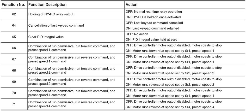
42 Logic Input Functions Table 14 below lists logic input functions available for programming parameters F108 F118 (logic inputs F, R, RES, and VIA). There are 57 available input types (0-71) that can be assigned to any one of these four parameters. Table 14: Logic Input Functions 42 IM 959
43 IM
44 44 IM 959
45 IM
46 Relay Output Functions Table 15 lists relay output functions available for programming parameters F130 F137 (relay outputs FLA, FLB, FLC, RY, RC). There are 52 available output types (0-61, 254, 255) that can be assigned to any one of these three parameters. Table 15: Relay Output Functions 46 IM 959
47 Table 15: Relay Output Functions, Continued IM
48 Table 15: Relay Output Functions, Continued 48 IM 959

49 Table 15: Relay Output Functions, Continued Analog Inputs Two analog inputs are supplied with the drive controller. Terminals VIA and VIB located on the bottom right terminal strip of the main unit control board are the analog inputs. If the drive controller has any communication card installed other than the default Modbus card, then the VIA analog output is not available. VIA can accept the following signal types: Voltage (V): 0-10 VDC, voltage or potentiometer input Current (I): 0-20 ma or 4-20 ma Selecting between a voltage or current signal (V or I) is done with the red switch 3 (SW3) located on the right side of the main control board. VIB can accept the following signal types: Voltage (V): 0-10 VDC, voltage or potentiometer input Basic parameter FNOD (Frequency Setting Mode Selection 1) determines which input signal the drive controller will use to control motor speed. Refer to Table 13 on page 37 for details. The scaling or slope of the analog input can be adjusted through extended parameters F201 F204 (for VIA), and F210 F213 (for VIB). Table 16: Scaling Analog Inputs VIA or VIB IM
50 Figure 17: Graphical Representation of Scaling the Default 0-10 VDC Analog Input Signal Figure 18: Graphical Representation of Scaling the Default 4-20 ma Analog Input Signal Any input can be scaled to control motor speed to any desired speed reference values. However, it is important to understand that as control range decreases, the resolution of control also decreases. Care must be taken when adjusting these parameters. Poor speed control may result if the analog input resolution is decreased too far. Analog Outputs One analog output is supplied with the drive controller. Terminal FM located on the bottom right terminal strip of the main unit control board is the analog output. FM is a multifunctional programmable analog output supplying an output frequency signal as the factory default. The FM terminal can output a voltage or current signal: When the red switch 2 (SW2) is set to V (voltage), FM outputs a 0-10 VDC signal at 1 ma When SW2 is set to I (current), FM outputs a 0-20 ma signal up to 24 VDC The specific type of signal that the FM terminal will output can be adjusted through parameter FNSL. There are 19 different values that can be programmed through parameter FNSL that effect what type of signal the FM terminal will output. 50 IM 959
51 Table 17: Analog Output Function Selection (Meter Selection) Scaling of the analog output through the FM terminal can be done in order to output a specific range of analog signal. The FM terminal will output a default 0-10 VDC signal if SW2 is set to V. The FM terminal will output a 0-20 ma signal if SW2 is set to I. In order to output any range other than the drive default, the following procedure must be carried out. 1. Set SW2 to the desired output, V (Voltage) or I (Current). 2. Change parameter FNSL to either 15 or 17 depending on the desired output. For current output, select 15; for voltage output, select Go to parameter Fn on the VFD display. Hit Enter. 100 should be displayed. 4. Disconnect all control wiring at terminal FM on the main unit control board. 5. With a digital multimeter measure the voltage or current at the FM terminal. For a voltage measurement, measure across FM and any common (CC) terminal. 6. Use the Up or Down keys to adjust the desired output range while measuring the value at the FM terminal with a digital multimeter. Notice that 100 is flashing on the display of the keypad even while voltage or current readings on the digital multimeter change. 7. Once the desired range has been set, hit Enter on the drive keypad. Fn and 100 should flash back and forth on the screen. This means that the desired output value has been locked in or set within the drive controller. IM
52 8. Go back to parameter FNSL on the drive display. Set it back to the desired type of output (output frequency, output current, etc.). Parameter Fn has an adjustable range of and is a unitless parameter. To find out what value was set at parameter Fn (to achieve the desired output) in steps 1 through 8, follow steps 9 through 11. This procedure is not necessary, but sometimes beneficial to record the actual value that was set at parameter Fn for future reference in case this parameter would happen to be changed, or set back to default at any point in the future. 9. Change parameter FNSL to 19. This setting displays the set value at parameter Fn. 10. Go to parameter Fn on the VFD display. Hit Enter. The true value that was locked or set at parameter Fn in steps 1 through 8 should be displayed. 11. Go back to parameter FNSL on the drive display. Set it back to the desired type of output (output frequency, output torque, etc.). PID Control The drive controller is equipped with its own internal PID loop for analog input signal control. The PID loop can be set to control to an analog input signal through the VIA terminal, VIB terminal, or a combination of both. The following procedure shows how to setup a PID control loop, and guidelines for tuning the loop. 1. Enable the PID control through parameter F360. It can be defined to control an analog input source at the VIA terminal or the VIB terminal. The default input for the enclosed drive controller is through the VIB terminal. The VIA analog input is not available on any other communication card option other than Modbus. Table 18: Enabling the PID loop and Defining the Feedback Source 2. Set parameter F359 to a desired value depending on the application. F359 is the PID control waiting period (in seconds). Parameter F359 defines the time period that the drive controller will ignore the feedback signal during PID control. The motor will accelerate to the speed set by the reference input during this time period. Table 19: Adjusting the PID Control Waiting Period 3. Set parameter FNOD to 3 (Keypad). Table 20: Frequency Setting Mode Selection Parameter Options (FNOD). 52 IM 959
53 4. Once FNOD is set to 3, hit Enter and press the Mode button twice. The drive is now put into a mode that allows the PID setpoint to be established by way of the keypad display. 5. Press the Up and Down arrows on the keypad until the desired PID setpoint shows on the display. Once the desired setpoint is displayed, press the Enter key to lock in the setpoint value (the value should blink for a few seconds when setpoint is locked in). Hit the Mode key to return back to the main display. PID Setpoint The PID setpoint is defined by the user and scaled according to parameters F202 and F204 for the VIA analog input. F211 and F213 define the scale for the PID setpoint through the VIB analog input. To understand what value should be entered on the keypad for a desired PID setpoint, the values entered in these parameters must be known. The transducer range feeding back an analog signal to the VIA or VIB terminal must also be known. Use the following examples to understand how to program in the correct PID setpoint at the keypad using one of the analog inputs (VIA, or VIB). Example 1 Transducer range = 0-5 inches of water column on an HVAC fan application Analog input range at VIA = 0-10 VDC Desired PID setpoint = 1.5 inches of water column PID value entered at the keypad to give a PID setpoint of 1.5 WC =??? 1. Understand what scaling values are entered at parameters F202 and F204. The drive controller default is: F202 = 0 Hz F204 = 60Hz 2. Understand what the transducer range is. In this example: Lowest point = 0 inches of water column Highest point = 5 inches of water column 3. Understand what the PID setpoint should be for the system. In this example, 1.5 inches of water column. 4. Conduct a linear interpolation between the five known values to come up with the unknown value (PID setpoint at the keypad): Table 21: Linear Interpolation to Find a Desired PID Setpoint to be Entered at the Keypad Display. Transducer Low Limit = 0 0 = F202 Value Desired PID Pressure Setpoint = 1.5?? = Desired PID Setpoint (to be entered at the keypad) Transducer High Limit = 5 60 = F204 Value The desired PID setpoint to be entered on the keypad display is 18 Hz, and is calculated the following way: (1.5 5) = 0.3 (or 30%) 0.3 X 60 = 18 Hz (desired setpoint) * Note: The analog input range (in this case 0-10 VDC) does not affect this calculation. However, the scaling of this input (0-10 VDC) is adjusted through parameter settings F201 and F203. IM
54 Example 2 Transducer range = 0-20 psi on a loop water pump application Analog input range at VIB = 4-20mA or 2-10VDC when a 500 ohm resistor is jumpered across VIB and CC (this must be done since VIB does not take a 4 20 ma feedback) Desired PID setpoint = 12 psi PID value entered at the keypad to give a PID setpoint of 12 psi =??? 1. Understand what scaling values are entered at parameters F211 and F213. The drive controller default is: F211 = 0 Hz F213 = 60Hz 2. Understand what the transducer range is. In this example: Lowest point = 0 psi Highest point = 20 psi 3. Understand what the PID setpoint should be for the system. In this example, 12 psi. 4. Conduct a linear interpolation between the 5 known values to come up with the unknown value (PID setpoint at the keypad): Table 22: Linear interpolation to find a desired PID setpoint to be entered at the keypad display. Transducer Low Limit = 0 0 = F211 Value Desired PID Pressure Setpoint = 12?? = Desired PID Setpoint (to be entered at the keypad) Transducer High Limit = = F213 Value The desired PID setpoint to be entered on the keypad display is 36 Hz, and is calculated the following way: (12 20) = 0.6 (or 60%) 0.6 X 60 = 36 Hz (desired setpoint) * Note: The analog input range (in this case 4-20 ma) does not affect this calculation. However, the scaling of this input (in this case) is adjusted through parameter settings F210 and F212. PID Tuning Once the PID loop is enabled and a setpoint established, tuning of the proportional and integral bands may be necessary if any of the following problems are occurring within the system: The VFD is hunting or ramping up and down sporadically. The VFD is not making speed adjustments fast enough to control to the PID setpoint. The VFD is making speed changes to fast, and trying to control to the PID setpoint too precisely. In order to alleviate these problems, four parameters may have to be adjusted to properly tune the PID feeback loop. It is recommended that the acceleration and deceleration parameters be set to a relatively low value to start, somewhere in the range of 1-10 seconds. Table 23: Acceleration and Deceleration Parameter Settings (in seconds) 54 IM 959
55 Next, adjust the proportional band (parameter F362), and the integral band (parameter F363) to values that yield the best possible control of the system, and get rid of any hunting or sporadic ramping problems in the loop. A rule of thumb is to set the integral band low (somewhere in the range or ), and the proportional band high (somewhere in the range of ). Table 24: Proportional Band Parameter Setting Parameter F362 adjusts the proportional gain applied during PID control. The speed change applied to the motor is a correctional value proportional to the product of this parameter s setting and the process error (deviation between the setpoint and the feedback value). Figure 19: Graphical Representation of the Proportional Gain Parameter Setting Table 25: Integral Band Parameter Setting Parameter F363 adjusts the integral gain applied during PID control. Any residual process errors that remain after correction by the proportional gain are cleared to zero over time by the integral gain function. A higher setting of F363 provides a fast response to a process error but may also result in instability in the system such as hunting. Figure 20 illustrates the effect produced by adjusting F363. Figure 20: Graphic Representation of the Integral Gain Parameter Setting IM
56 Floating Point Control Many of McQuay s applied air products utilize a floating point control scheme to control motor speed. This type of control utilizes dry contact relays in order to increase or decrease the speed of the drive controller. A typical control wire scheme to carry out this type of control is shown in Figure 23. Figure 21: Typical Control Wiring Diagram for Floating Point Control The parameter changes necessary to achieve this type of motor control are listed in Table 26 below. Table 26: Parameter Changes for Floating Point Control Parameter Description Default Setting Floating Point Control Setting Fnod Frequency setting mode selection F112 Input terminal selection 2 ( R ) 6 41 F113 Input terminal selection 3 (RES) IM 959
57 Wiring Diagram Figure 22: Typical Wiring Schematic for McQuay Enclosed Drive Controllers (460V shown) IM
58 Troubleshooting Refer to Tables 27 and 29 to diagnose and resolve problems when a fault or alarm occurs. A fault will cause the drive to stop supplying power at its output terminals, causing the motor to completely stop. An alarm will not cause the drive to stop supplying power to its output terminals, but will show the alarm code on the keypad display of the drive controller. If the problem cannot be resolved by the actions described in the tables, contact one of the product support options shown on page 70 of this manual, or contact your McQuay Parts Distributor. Drive Controller Fault Conditions Table 27: Fault Codes 58 IM 959
59 Table 27: Fault Codes, Continued IM
60 Table 27: Fault Codes, Continued 60 IM 959
61 Table 27: Fault Codes, Continued IM
62 Table 27: Fault Codes, Continued 62 IM 959

63 Pre-alarm Displays The drive controller has several pre-alarm codes that will display before an actual fault occurs. Pre-alarms are displayed, blinking, in the following order from left to right: C, P, L, H. If two or more problems arise simultaneously, one of the following alarms appears and blinks: CP, PL, CPL. Table 28: Pre-alarm Displays IM
Instruction Bulletin. ALTIVAR 58 Adjustable Speed Drive Controllers
 Instruction Bulletin 30072-450-01 August 1998 Raleigh, NC, USA ALTIVAR 58 Adjustable Speed Drive Controllers Installation Guide Type N Controllers DANGER HAZARDOUS VOLTAGE Read and understand this bulletin
Instruction Bulletin
 Instruction Bulletin 30072-450-01A February 2003 Raleigh, NC, USA ALTIVAR 58 TRX Adjustable Speed Drive Controllers Installation Guide Type N Controllers DANGER HAZARDOUS VOLTAGE Read and understand this
PART 1: GENERAL PART 2: PRODUCT. Effective: 12/29/10 Page 1 of 6 FECA-TE-104D
 Specification Number: 23 09 33 Product Name: FRENIC-Eco AC Drives for Variable Torque Fan & Pump Applications (1-125Hp at 208/230V and 1-900Hp at 460V) PART 1: GENERAL 1.01 SUMMARY A. This specification
Altivar 21 Programming and Operation Guide
 Altivar 21 Programming and Operation Guide Instruction Bulletin 372-451-63 Retain for future use. 372-451-63 Altivar 21 Programming and Operation Guide 3/27 Table of Contents Hazard Categories and Special
Quick Start Guide TS A
 Quick Start Guide TS 930 125-630A DANGER HAZARD OF ELECTRICAL SHOCK, EXPLOSION, OR ARC FLASH Read and understand this quick start guide before installing and operating the transfer switch The installer
User s Manual. ACS550-PD 3R Irrigation Packaged Drive Supplement to ACS550-U1 User s Manual
 User s Manual ACS550-PD 3R Irrigation Packaged Drive Supplement to ACS550-U1 User s Manual 2 ACS550-PD 3R Irrigation Packaged Drive ACS550 Drive Manuals GENERAL MANUALS ACS550-U1 User s Manual (1 200 HP)
Table of Contents. Safety. Attention. Warnings
 Solstart Miniature Soft Starter 8-58A, 220-600V Instruction Manual Ver. 21.2. 2002 Table of Contents Page Subject 3 Starter Selection 4 Installation Notes 5 Wiring 6 Starter Settings & Start-up Procedure
MD2 Variable Speed Drive Controllers
 Operation and Maintenance Manual OM 844-2 MD2 Variable Speed Drive Controllers Group: Applied Air Systems Part Number: OM 844 Date: September 2009 Packaged Rooftop Units RPS, RFS, RDT, RPE, and RDE Rooftop
PowerLogic High Density Metering System 1-Meter Enclosure
 PowerLogic High Density Metering System 1-Meter Enclosure Installation Guide 63230-508-211A1 Safety information PowerLogic High Density Metering System 1-Meter Enclosure Important information Read these
Instruction Bulletin A August, 1995 Replaces dated 4/93 Price: $10.00
 Instruction Bulletin August, 1995 Replaces 50006-360-01 dated 4/93 Price: $10.00 a 16 Adjustable Speed AC Drive Controller for Asynchronous Motors ALTIVAR 16 Drive Controller for Asynchronous Motors August,
VLT 2800 DRIVE SPECIFICATIONS
 VLT 2800 DRIVE SPECIFICATIONS Drive Input Power Input voltage 3 phase... 200 through 240, or 380 through 460; 3-phase all ratings 200 through 240, 1-phase through 2 HP Input voltage range for full output...
Powered to Perform. Everyday Reliability. Exceptional Value. Expertise and Support
 A decentralized solution. Many drive applications utilize control panels with complex wiring taking up large amounts of space. These control panels are often mounted away from the application requiring
SED2 VFD NEMA Type 3R Bypass/Air Conditioner
 SED2 VFD NEMA Type 3R Bypass/Air Conditioner Description The NEMA Type 3R Bypass with Air Conditioner allows SED2 to be employed in a harsh environment. The SED2 is designed specifically for HVAC applications
SECTION VARIABLE FREQUENCY DRIVES
 PART 1 GENERAL 1.01 DESCRIPTION This specification section establishes the requirements for variable frequency motor drives. The associated motor(s) shall be specified separate from the drive and listed
PowerFlex 400 AC Drive Guide Specification
 PowerFlex 400 AC Drive Guide Specification Adjustable Frequency Drives with Bypass 3.0 50HP @ 208V AC 3.0 350HP @ 480V AC PART 1 GENERAL 1.01 Quality Assurance A. The manufacturer shall have minimum 5
BT300 HVAC Drives Electronic Bypass (E-Bypass) Options
 Options") BT300 HVAC Drives Electronic Bypass (E-Bypass) Options Description The BT300 Electronic Bypass (E-Bypass) Options are companion packages for the family of BT300 Variable Frequency Drives (VFDs). For information
BT300 HVAC Drives Electronic Bypass (E-Bypass) Options Description The BT300 Electronic Bypass (E-Bypass) Options are companion packages for the family of BT300 Variable Frequency Drives (VFDs). For information
PowerFlex 40 Sample Specification
 PowerFlex 40 Sample Specification GENERAL REFERENCES REGULATORY REQUIREMENTS Designed to meet the following specifications: NFPA 70 - US National Electrical Code NEMA ICS 3.1 - Safety standards for Construction
Q9 ASD LOW VOLTAGE DRIVE
 ASD LOW VOLTAGE DRIVE HVAC-MINDED, SYSTEM FRIENDLY RELIABLE Toshiba has manufactured pulse-width modulated drives since 1981 and is one of the few companies that manufactures both motors and drives in
SED2 Variable Frequency Drives with Electronic (E) Bypass Options
 Bypass Options") SED2 Variable Frequency Drives with Electronic (E) Options Description The E- Options are companion packages for the family of SED2 Variable Frequency Drives (s). For information on the family of SED2
SED2 Variable Frequency Drives with Electronic (E) Options Description The E- Options are companion packages for the family of SED2 Variable Frequency Drives (s). For information on the family of SED2
Installation Instructions
 50ES, 50EZ, 50GL, 50GS, 50GX, 50JS, 50JX, 50JZ, 50SD, 50SZ, 50VL, 50VT, 50XP, 50XZ 601A, 602A, 602B, 604A, 604B, 604D, 607C, 701A, 702A, 702B, 704A, 704B, 704D, 707C PA1P, PA2P, PA3P, PH1P, PH2P, PH3P
SORDS ELECTRIC ~ MA7200. Sensorless Vector AC Inverter.
 www.sordselectric.com MA7200 Sensorless Vector AC Inverter Features and Benefits Sensorless Vector The MA7200 has precise speed and torque control for the most demanding system performance and simple set-up
Installation, Operation and Maintenance Manual
 Document 481200 VGD-100 Vari-Green Drive Installation, Operation and Maintenance Manual Please read and save these instructions for future reference. Read carefully before attempting to assemble, install,
A drive dedicated to variable speed control for HVAC applications
 A drive dedicated to variable speed control for HVAC applications Designed for easy installation in mechanical fan and pump systems with reliable connectivity to building automation networks. VTAC 9 Drive
DANGER DANGER: is used in this manual to warn of high voltages capable of causing shock, burns, or death.
 Installation/Operation Manual TABLE OF CONTENTS Page UNPACKING AND INSTALLATION Unpacking and Preliminary Inspection...2, 3 Model Number...9 LOCATION CONSIDERATIONS Environment, Equipment Performance,
ATV212HD18N4 variable speed drive ATV kW - 25hp - 480V - 3ph - EMC - IP21
 Characteristics variable speed drive ATV212-18.5kW - 25hp - 480V - 3ph - EMC - IP21 Main Range of product Altivar 212 Product or component type Device short name Product destination Product specific application
PanelView Plus/VersaView CE Terminals and Display Modules
 Installation Instructions PanelView Plus/VersaView CE Terminals and Display Modules (Catalog Numbers 2711P-xxxxxx, 6182H-xxxxxx) English Inside: Overview...2 For More Information...2 Modular Components...3
P216 Series Condenser Fan Speed Controller
 P216 Series Condenser Fan Speed Controller Installation Instructions P216xxx-x Part No. 24-85895-18, Rev. D Issued 27 August 2015 Applications Refer to the QuickLIT website for the most up-to-date version
MD2 Variable Speed Drive Controllers
 Operation and Maintenance Manual OM 844 Group: Rooftop Systems Part Number: OM 844 Date: August 2006 MD2 Variable Speed Drive Controllers Packaged Rooftop Units RPS, RFS, RDT, RPE, and RDE Rooftop Air
ATS22D75S6 soft starter-ats22-control 220V-power 230V(18.5kW)/ V(37kW)/500V(45kW)
/ V(37kW)/500V(45kW)") Characteristics soft starter-ats22-control 220V-power 230V(18.5kW)/400...440V(37kW)/500V(45kW) Price* : 683.00 GBP Main Range of product Altistart 22 Product or component type Product destination Product
Characteristics soft starter-ats22-control 220V-power 230V(18.5kW)/400...440V(37kW)/500V(45kW) Price* : 683.00 GBP Main Range of product Altistart 22 Product or component type Product destination Product
Motor Controllers AC Variable Frequency Drives Type VariFlex 3 RVFF
 ype VariFlex 3 RVFF RVFF AC variable speed drive for use with AC induction motors Sensorless vector control or V/F, SLV, PMSLV with space vector PWM mode Input voltage ranges: 3-ph 480VAC 150%/1Hz (vector
ATV212HD11N4 variable speed drive ATV212-11kW - 15hp - 480V - 3ph - EMC - IP21
 Characteristics variable speed drive ATV212-11kW - 15hp - 480V - 3ph - EMC - IP21 Main Range of product Altivar 212 Product or component type Device short name Product destination Product specific application
ATS22D62Q soft starter-ats22-control 220V-power 230V(15kW)/ V(30kW)
/ V(30kW)") Characteristics soft starter-ats22-control 220V-power 230V(15kW)/400...440V(30kW) Main Range of product Altistart 22 Product or component type Product destination Product specific application Component
Characteristics soft starter-ats22-control 220V-power 230V(15kW)/400...440V(30kW) Main Range of product Altistart 22 Product or component type Product destination Product specific application Component
User s Manual. ACS550-PD Stock 3R Irrigation Packaged Drive Supplement to ACS550-U1 User s Manual
 User s Manual ACS550-PD Stock 3R Irrigation Packaged Drive Supplement to ACS550-U1 User s Manual 2 ACS550-PD 3R Irrigation Packaged Drive ACS550 Drive Manuals GENERAL MANUALS ACS550-U1 User s Manual (1
SP500 AC Drive Installation and Operation Manual Version 3.1
 SP500 AC Drive Installation and Operation Manual Version 3. Instruction Manual D2-3356-5 The information in this manual is subject to change without notice. Throughout this manual, the following notes
P216. Condenser fan speed controller. Product bulletin. Features
 P216 Condenser fan speed controller Product bulletin These controllers are designed for speed variation of single phase motors, especially for fan speed control on air cooled condensers. Head pressure
ABB Industrial Systems Inc. Standard Drives. ACH500-06E Effective 6/1/95
 Part 1 - GENERAL ASEA BROWN BOVERI ABB Industrial Systems Inc. Standard Drives ACH500-06E Effective 6/1/95 Sample Specification for Adjustable Frequency Drives (2 to 400 HP) for Variable Torque Applications
ATV212WU55N4 variable speed drive ATV kW - 7.5hp - 480V - 3ph - EMC class C2 - IP55
 Product data sheet Characteristics ATV212WU55N4 variable speed drive ATV212-5.5kW - 7.5hp - 480V - 3ph - EMC class C2 - IP55 Complementary Apparent power Prospective line Isc Continuous output current
ATS22D75S6U. Main. Range of product Altistart 22. Component name. Factory setting current. Utilisation category. IP degree of protection
 Product datasheet Characteristics ATS22D75S6U Complementary Assembly style Function available Supply voltage limits Main Range of product Altistart 22 Product or component type Product destination Product
ATV310HU30N4E variable speed drive ATV310-3 kw - 4 hp V - 3 phase
 Characteristics variable speed drive ATV310-3 kw - 4 hp - 380...460 V - 3 phase Complementary Product destination Main Range of product Altivar Easy 310 Product or component type Product specific application
SED2 Variable Frequency Drives
 SED2 Variable Frequency Drives Startup Procedure and Checklist Document No. 155-718 Table of Contents Prerequisites...1 Preparing for SED2 VFD Startup...1 HVAC Startup Procedure for SED2 with Bypass Option...4
The PCI Series. Precise power control for complex SCR applications. Phase Angle Fired SCR Power Controls AMPS VAC
 The PCI Series Phase Angle Fired SCR Power Controls 25-1200 AMPS 120-600 VAC Precise power control for complex SCR applications. ROBICON 1996 Distributed Worldwide by www.mcgoff-bethune.com Applications
ATV212WU40N4 variable speed drive ATV212-4kW - 5hp - 480V - 3ph - EMC class C2 - IP55
 Characteristics variable speed drive ATV212-4kW - 5hp - 480V - 3ph - EMC class C2 - IP55 Main Range of product Altivar 212 Product or component type Device short name Product destination Product specific
ATV212HD15N4 variable speed drive ATV212-15kW - 20hp - 480V - 3ph - EMC - IP21
 Product data sheet Characteristics ATV212HD15N4 variable speed drive ATV212-15kW - 20hp - 480V - 3ph - EMC - IP21 Complementary Apparent power Prospective line Isc Continuous output current Maximum transient
Motor Controllers AC Variable Frequency Drives Type VariFlex 3 RVFF
 ype VariFlex 3 RVFF RVFF AC variable speed drive for use with AC induction motors Sensorless vector control or V/F, SLV, PMSLV with space vector PWM mode Input voltage ranges: 3-ph 480VAC 50%/Hz (vector
Installation and Operation Manual D SP500 AC Drive. Version 3.1
 Installation and Operation Manual D2-3356-6 SP500 AC Drive Version 3. Important User Information Solid-state equipment has operational characteristics differing from those of electromechanical equipment.
AF-600 FP TM Fan & Pump Drive. (230V to 60HP, 460/575V to 125HP Operating Instructions
 GE AF-600 FP TM Fan & Pump Drive (230V to 60HP, 460/575V to 125HP Operating Instructions Safety Safety WARNING HIGH VOLTAGE! Frequency converters contain high voltage when connected to AC mains input power.
ATS22D17Q soft starter-ats22-control 220V-power 230V (4kW)/ V(7.5kW)
/ V(7.5kW)") Product datasheet Characteristics ATS22D17Q soft starter-ats22-control 220V-power 230V (4kW)/400...440V(7.5kW) Complementary Assembly style Function available Supply voltage limits Main Range of product
Product datasheet Characteristics ATS22D17Q soft starter-ats22-control 220V-power 230V (4kW)/400...440V(7.5kW) Complementary Assembly style Function available Supply voltage limits Main Range of product
ATS22C17Q. Main. Range of product Altistart 22. Component name. Factory setting current. Utilisation category. IP degree of protection
 Product datasheet Characteristics ATS22C17Q Complementary Assembly style Function available Supply voltage limits Main Range of product Altistart 22 Product or component type Product destination Product
ATS22D17Q soft starter-ats22-control 220V-power 230V(4kW)/ V(7.5kW)
/ V(7.5kW)") Characteristics soft starter-ats22-control 220V-power 230V(4kW)/400...440V(7.5kW) Main Range of product Altistart 22 Product or component type Product destination Product specific application Component
Characteristics soft starter-ats22-control 220V-power 230V(4kW)/400...440V(7.5kW) Main Range of product Altistart 22 Product or component type Product destination Product specific application Component
S-Flex Enclosed Drive
 S-Flex Enclosed Drive The best drive for commercial pump and fan applications. Make the most of your energy SM years For more than 100 years the Square D brand has been known for the most reliable electrical
ATS22D75Q soft starter-ats22-control 220V-power 230V(18.5kW)/ V(37kW)
/ V(37kW)") Product data sheet Characteristics ATS22D75Q soft starter-ats22-control 220V-power 230V(18.5kW)/400...440V(37kW) Complementary Assembly style Function available Power supply voltage limits Main Range of
Product data sheet Characteristics ATS22D75Q soft starter-ats22-control 220V-power 230V(18.5kW)/400...440V(37kW) Complementary Assembly style Function available Power supply voltage limits Main Range of
CHAPTER MAINTENANCE AND TROUBLESHOOTING. In This Chapter... Maintenance and Inspection Troubleshooting...6 3
 CHAPTER MAINTENANCE AND 6 TROUBLESHOOTING In This Chapter... Maintenance and Inspection..........................6 2 Monthly Inspection...................................6 2 Annual Inspection....................................6
PART 1: GENERAL PART 2: PRODUCT. Phone: Fax: Web: -
 Specification Number: 23 09 33 Product Name: FRENIC-HVAC AC Drives for Variable Torque Fan & Pump Applications (1-125Hp at 208/230Vac, 1-1000Hp at 460Vac, 1-300Hp at 575Vac) PART 1: GENERAL 1.01 SUMMARY
SED2 Variable Frequency Drives Conventional Bypass (C-Bypass) Options
 Options") Submittal Sheet SED2 Variable Frequency Drives Conventional Bypass (C-Bypass) Options Description The Bypass Options are companion packages for the family of SED2 Variable Frequency Drives. For information
Submittal Sheet SED2 Variable Frequency Drives Conventional Bypass (C-Bypass) Options Description The Bypass Options are companion packages for the family of SED2 Variable Frequency Drives. For information
E510. Compact Drive IP 20/ NEMA HP (230V) 1-75 HP (460V)
 1-75 HP (460V)") E510 Compact Drive IP 20/ NEMA 1 0.5-40 HP (230V) 1-75 HP (460V) Control Mode Application & Selection Guide The E510 compact AC Drive is an easily configurable product that controls many motor driven applications.
E510 Compact Drive IP 20/ NEMA 1 0.5-40 HP (230V) 1-75 HP (460V) Control Mode Application & Selection Guide The E510 compact AC Drive is an easily configurable product that controls many motor driven applications.
ATS22D88S6U. ATS22D88S6U soft starter-ats22-control110v-power 208V(25hp)/230V(30hp)/460V(60hp)/575V(75hp) Product data sheet Characteristics.
/230V(30hp)/460V(60hp)/575V(75hp) Product data sheet Characteristics.") Characteristics soft starter-ats22-control110v-power 208V(25hp)/230V(30hp)/460V(60hp)/575V(75hp) Main Range of product Altistart 22 Product or component type Product destination Product specific application
Characteristics soft starter-ats22-control110v-power 208V(25hp)/230V(30hp)/460V(60hp)/575V(75hp) Main Range of product Altistart 22 Product or component type Product destination Product specific application
ATS22C21S6U softstarter-ats22-control110vpower208v(60hp)/230v(75hp)/460v(150hp)/575v(200hp)
/230v(75hp)/460v(150hp)/575v(200hp)") Characteristics softstarter-ats22-control110vpower208v(60hp)/230v(75hp)/460v(150hp)/575v(200hp) Main Range of product Altistart 22 Product or component type Product destination Product specific application
Characteristics softstarter-ats22-control110vpower208v(60hp)/230v(75hp)/460v(150hp)/575v(200hp) Main Range of product Altistart 22 Product or component type Product destination Product specific application
ATS22C11S6U soft starter-ats22-control110vpower208v(30hp)/230v(40hp)/460v(75hp)/575v(100h
/230v(40hp)/460v(75hp)/575v(100h") Characteristics soft starter-ats22-control110vpower208v(30hp)/230v(40hp)/460v(75hp)/575v(100h Complementary Assembly style Function available Power supply voltage limits Main Range of product Altistart
Characteristics soft starter-ats22-control110vpower208v(30hp)/230v(40hp)/460v(75hp)/575v(100h Complementary Assembly style Function available Power supply voltage limits Main Range of product Altistart
FLÄKTGROUP OFFERS A WIDE RANGE OF PER- MANENT MAGNET MOTORS (PM) AND FREQUENCY CONVERTERS FOR PLUG FANS. POWER RANGE IS FROM 0,8 KW TO 15 KW.
 AND FREQUENCY CONVERTERS FOR PLUG FANS. POWER RANGE IS FROM 0,8 KW TO 15 KW.") CENTRIFLOW PUR 3D (A, PLUG B, C, D) FAN GMPM FC101 AND SLIDE IN FREQUENCY ROTOR CASSETTE CONVERTER QUICK GUIDE FLÄKTGROUP OFFERS A WIDE RANGE OF PER- MANENT MAGNET MOTORS (PM) AND FREQUENCY CONVERTERS
CENTRIFLOW PUR 3D (A, PLUG B, C, D) FAN GMPM FC101 AND SLIDE IN FREQUENCY ROTOR CASSETTE CONVERTER QUICK GUIDE FLÄKTGROUP OFFERS A WIDE RANGE OF PER- MANENT MAGNET MOTORS (PM) AND FREQUENCY CONVERTERS
S-Flex Enclosed drives
 Water Circulation Pumps & Circulators S-Flex Enclosed drives The S-Flex enclosed drive, designed with input from HVAC consultants and contractors, was developed specifically for commercial pump applications,
WARNING UNINTENDED EQUIPMENT OPERATION
 Operation Manual Variable Frequency Drive (VFD) 7 ½ - 25 Ton Units with ClearControl TM WARNING UNINTENDED EQUIPMENT OPERATION Modifying or changing parameters whose function is not described in this manual
PHASETRONICS. SCR Power Control Specialists. EP1 Series Power Control Single Phase SCR Amps OPERATION & SERVICE MANUAL
 PHASETRONICS Specialists EP1 Series Power Control Single Phase SCR 10-50 Amps OPERATION & SERVICE MANUAL Phasetronics, Inc. P.O. Box 5988 1600 Sunshine Drive Clearwater, FL 33765 (727)573-1900 FAX(727)573-1803
ATV212HU55N4 variable speed drive ATV kW - 7.5hp - 480V - 3ph - EMC - IP21
 Product data sheet Characteristics ATV212HU55N4 variable speed drive ATV212-5.5kW - 7.5hp - 480V - 3ph - EMC - IP21 Complementary Apparent power Prospective line Isc Continuous output current Maximum transient
UNT1100 Series. Binary Output Jumpers AO2 AO1 AO3 AO4 AOCM AOCM AOCM AOCM AO1. AI Switches Job Information N2 Address. Ref N2+ N2- ADDR 0 = ALL OPEN
 1 2 8 4 AI6 R R Installation Bulletin UNT1100 Issue Date 0309 UNT1100 Series Introduction The Unitary (UNT) controller (UNT1100 Series) is a digital controller with applications for air handling units,
Installation Manual Updated May 2017
 Code No. LIT-12012114 Installation Manual Updated May 2017 JC-VSD Factory Packaged (FP) Series II drive frames 4 8, Type 1 and 3R Johnson Controls variable speed drives Disclaimer of warranties and limitation
ATV212HU55N4 variable speed drive ATV kW - 7.5hp - 480V - 3ph - EMC - IP21
 Characteristics variable speed drive ATV212-5.5kW - 7.5hp - 480V - 3ph - EMC - IP21 Main Range of product Altivar 212 Product or component type Device short name Product destination Product specific application
ATS22D47S6U. Main. Range of product Altistart 22. Component name. Factory setting current. Utilisation category. IP degree of protection
 Product datasheet Characteristics ATS22D47S6U Complementary Assembly style Function available Supply voltage limits Main Range of product Altistart 22 Product or component type Product destination Product
Installation and Operation Manual
 Installation and Operation Manual APC 2X Series Hardwire Products PMP2X-A PMF2X-A PMG2X-A PMH2X-A APC hardwired products are designed to provide specification-grade performance at the service entrance,
HUBBELL SPIKESHIELD Wired-In Branch Panels Surge Protective Device (SPD)
") HUBBELL SPIKESHIELD Wired-In Branch Panels Surge Protective Device (SPD) Instruction Bulletin 8222-0513B Retain for future use. SPIKESHIELD Wired-In Branch Panels 8222-0513B 05/2012 Table of Contents Precautions...
HUBBELL SPIKESHIELD Wired-In Branch Panels Surge Protective Device (SPD) Instruction Bulletin 8222-0513B Retain for future use. SPIKESHIELD Wired-In Branch Panels 8222-0513B 05/2012 Table of Contents Precautions...
ATV212HD75N4. Main. Range of product Altivar 212. Device short name. Motor power hp 160 A 460 V khz with derating factor
 Product datasheet Characteristics ATV212HD75N4 Complementary Apparent power Prospective line Isc Continuous output current Maximum transient current Speed drive output frequency Nominal switching frequency
PLT. Breaker-based transfer switch open, closed or soft transition amps. Specification sheet
 Specification sheet PLT Breaker-based transfer switch open, closed or soft transition 800 3000 amps Description PLT breaker-based transfer switches are designed for operation and switching of electrical
Pump Data Sheet - Patterson HVAC Pumps Company: Intermountain Hydron Name: Cache County Mountain Crest Date: 09/24/2018
 Pump Data Sheet - Patterson HVAC Pumps Company: Intermountain Hydron Name: Cache County Mountain Crest Date: 09/24/2018 Tags: P-8 1800RPM Premium Efficient Motor 460/3/60 Pump and Motor Weight: 183lbs
AP Series Variable Frequency Drives Operation & Installation Manual
 AP Series Variable Frequency Drives Operation & Installation Manual i SAFETY MESSAGES AND WARNINGS To ensure safe and reliable operation of the AquaPhase AP Series pump converter, it is important to carefully
ADJUSTABLE SPEED DRIVES. Q9 Series
 ADJUSTABLE SPEED DRIVES Q9 Series Reliable & Configurable Reliable Toshiba has manufactured pulse-width modulated drives since 1981 and is one of the few companies that manufactures both motors and drives
TR200 DRIVE STANDARD FEATURES
 TR200 DRIVE STANDARD FEATURES The TR200 Trane Drive The TR200 Drive Series is a microprocessorbased, high frequency IGBT-based, PWM AC drive with control functions and software designed solely for the
SED2 Variable Frequency Drives
 Building Technologies SED2 Variable Frequency Drives More standard features Means better control of HVAC applications The global leader in Heating, Ventilation and Air Conditioning (HVAC) products and
ATV310H075N4E variable speed drive ATV kw - 1 hp V - 3 phase
 Characteristics variable speed drive ATV310-0.75 kw - 1 hp - 380...460 V - 3 phase Main Range of product Altivar Easy 310 Product or component type Product specific application Assembly style Device short
ATS22C41Q soft starter-ats22-control 220V-power 230V(110kW)/ V(220kW)
/ V(220kW)") Characteristics soft starter-ats22-control 220V-power 230V(110kW)/400...440V(220kW) Complementary Assembly style Function available Power supply voltage limits Main Range of product Altistart 22 Product
Characteristics soft starter-ats22-control 220V-power 230V(110kW)/400...440V(220kW) Complementary Assembly style Function available Power supply voltage limits Main Range of product Altistart 22 Product
ATV12HU22M3 variable speed drive ATV12-2.2kW - 3hp V - 3ph - with heat sink
 Characteristics variable speed drive ATV12-2.2kW - 3hp - 200..240V - 3ph - with heat sink Main Range of product Altivar 12 Product or component type Product destination Product specific application Assembly
ATV12H018M2 variable speed drive ATV kW hp V - 1ph
 Characteristics variable speed drive ATV12-0.18kW - 0.25hp - 200..240V - 1ph Complementary Main Range of product Altivar 12 Product or component type Product destination Product specific application Assembly
ATV212WD30N4 variable speed drive ATV212-30kW - 40hp - 480V - 3ph - EMC class C2 - IP55
 Product data sheet Characteristics ATV212WD30N4 variable speed drive ATV212-30kW - 40hp - 480V - 3ph - EMC class C2 - IP55 Complementary Apparent power Prospective line Isc Continuous output current Maximum
ATV12P037F1 variable speed drive ATV kW hp V - 1ph - on base plate
 Characteristics variable speed drive ATV12-0.37kW - 0.55hp - 100..120V - 1ph - on base plate Complementary Main Range of product Altivar 12 Product or component type Product destination Product specific
Easy To Use OEMS Take Note
 MA7200 Features Sensorless Vector Precise speed and torque control for the most demanding system performance. Simple set-up through autotuning function. The MA7200 can be operated in sensorless vector
ACCESS 9340/9360 Meter Input/Output Module
 Installation Manual PMIM-IOMOD-0208 ACCESS 9340/9360 Meter Input/Output Module 9340-60-I/O2222 and 9340-60-I/O26 HAZARD CATEGORIES AND SPECIAL SYMBOLS Read these instructions carefully and look at the
Installation Instructions
 Installation Instructions Variable Frequency Drive (VFD) 7 ½ - 25 Ton Units with 2 Wire Control WARNING UNINTENDED EQUIPMENT OPERATION Modifying or changing parame eters whose function is not described
Line reactors SINAMICS. SINAMICS G130 Line reactors. Safety information 1. General. Mechanical installation 3. Electrical installation
 Safety information 1 General 2 SINAMICS SINAMICS G130 Mechanical installation 3 Electrical installation 4 Technical specifications 5 Operating Instructions Control version V4.7 04/2014 A5E00331462A Legal
SECTION VARIABLE FREQUENCY MOTOR CONTROLLERS (VFD)
") SECTION 26 29 23 VARIABLE FREQUENCY MOTOR CONTROLLERS (VFD) PART 1 -GENERAL 1.1 SYSTEM DESCRIPTION A. Definitions: The Variable Speed AC Motor Drive (hereafter referred to as "VFD") shall be designed to
SECTION 26 29 23 VARIABLE FREQUENCY MOTOR CONTROLLERS (VFD) PART 1 -GENERAL 1.1 SYSTEM DESCRIPTION A. Definitions: The Variable Speed AC Motor Drive (hereafter referred to as "VFD") shall be designed to
Analog Monitor Installation Manual
 Analog Monitor Installation Manual Part Number: 144-23919 Copyright 2011 Magnetek 1. Preface and Safety Magnetek manufactures products used as components in a wide variety of industrial systems and equipment.
ATV12H075M3 variable speed drive ATV kW - 1hp V - 3ph - with heat sink
 Product datasheet Characteristics ATV12H075M3 variable speed drive ATV12-0.75kW - 1hp - 200..240V - 3ph - with heat sink Complementary Main Range of product Altivar 12 Product or component type Product
AC Tech. Variable Speed AC Motor Drives. SCN Series Installation and Operation Manual
 AC Tech Variable Speed AC Motor Drives SCN Series Installation and Operation Manual Manual Number: IMSN02 TABLE OF CONTENTS 1.0 GENERAL... 1 2.0 SCN DIMENSIONS... 2 3.0 SCN MODEL DESIGNATION CODE... 3
ATV12P075M3 variable speed drive ATV kW - 1hp V - 3ph - on base plate
 Characteristics variable speed drive ATV12-0.75kW - 1hp - 200..240V - 3ph - on base plate Main Range of product Altivar 12 Product or component type Product destination Product specific application Assembly
ATV212HD11M3X variable speed drive ATV212-11kW - 15hp - 240V - 3ph -wo EMC - IP21
 Characteristics variable speed drive ATV212-11kW - 15hp - 240V - 3ph -wo EMC - IP21 Product availability : Stock - Normally stocked in distribution facility Price* : 1398.00 USD Main Range of product Altivar
Specification Number: Product Name: FRENIC-Mega AC Drives for General Purpose Applications (½ - 150Hp at 230V and ½ Hp at 460V)
") Specification Number: 26 29 23 Product Name: FRENIC-Mega AC Drives for General Purpose Applications (½ - 150Hp at 230V and ½ - 1000Hp at 460V) PART 1: GENERAL 1.01 SUMMARY A. This specification provides
Specification Number: 26 29 23 Product Name: FRENIC-Mega AC Drives for General Purpose Applications (½ - 150Hp at 230V and ½ - 1000Hp at 460V) PART 1: GENERAL 1.01 SUMMARY A. This specification provides
HVAC Products. Introducing the SED2 Variable Frequency Drives
 HVAC Products Introducing the SED2 Variable Frequency Drives Designed Specifically for HVAC Applications From a global leader in drives technology and innovation, now comes a drive specifically configured
ATV212HD15N4 variable speed drive ATV212-15kW - 20hp - 480V - 3ph - EMC - IP21
 Product datasheet Characteristics ATV212HD15N4 variable speed drive ATV212-15kW - 20hp - 480V - 3ph - EMC - IP21 Complementary Apparent power Prospective line Isc Continuous output current Maximum transient
GV3000/SE 230 VAC 1-20 HP General Purpose (Volts/Hertz) and Vector Duty Drive Software Start-Up and Reference Manual Version 6.04
 and Vector Duty Drive Software Start-Up and Reference Manual Version 6.04") GV3000/SE 230 VAC 1-20 HP General Purpose (Volts/Hertz) and Vector Duty Drive Software Start-Up and Reference Manual Version 6.04 Instruction Manual D2-3387-4 The information in this manual is subject
GV3000/SE 230 VAC 1-20 HP General Purpose (Volts/Hertz) and Vector Duty Drive Software Start-Up and Reference Manual Version 6.04 Instruction Manual D2-3387-4 The information in this manual is subject
Quick Start Guide TS 870 ATS
 Quick Start Guide TS 870 ATS 100A - 800A (with TSC 900 Controller) DANGER HAZARD OF ELECTRICAL SHOCK, EXPLOSION, OR ARC FLASH Read and understand this quick start guide before installing and operating
ATS22C11S6U soft starter-ats22-control110vpower208v(30hp)/230v(40hp)/460v(75hp)/575v(100hp)
/230v(40hp)/460v(75hp)/575v(100hp)") Characteristics soft starter-ats22-control110vpower208v(30hp)/230v(40hp)/460v(75hp)/575v(100hp) Product availability : Stock - Normally stocked in distribution facility Price* : 1468.00 USD Main Range
Characteristics soft starter-ats22-control110vpower208v(30hp)/230v(40hp)/460v(75hp)/575v(100hp) Product availability : Stock - Normally stocked in distribution facility Price* : 1468.00 USD Main Range
BT300 HVAC Drives. Designed for HVAC. Description. Technical Specification Sheet Document No March 4, 2013
 Technical Specification Sheet Document No. 149-711 March 4, 2013 BT300 HVAC Drives Designed for HVAC Figure 1. BT300 HVAC Drive without and with Integral Disconnect. Description Siemens Industry's BT300
ATV212HD30N4 variable speed drive ATV212-30kW - 40hp - 480V - 3ph - EMC - IP21
 Product datasheet Characteristics ATV212HD30N4 variable speed drive ATV212-30kW - 40hp - 480V - 3ph - EMC - IP21 Complementary Apparent power Prospective line Isc Continuous output current Maximum transient