The Butterfly LaserMount also offers all the features you would expect from a modern butterfly laser diode fixture, including:
|
|
|
- Betty Farmer
- 5 years ago
- Views:
Transcription


1

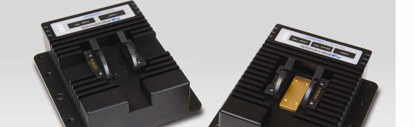
2 Page 2 202/204 Butterfly LaserMount User s Manual Introduction Thank you for choosing the Butterfly LaserMount from Arroyo Instruments. The Butterfly LaserMount is designed for high performance and long term use, with innovative features not found in other butterfly mounts. One such feature is field-replaceable butterfly connectors. A common problem in production applications is the wear and tear on the Azimuth butterfly connectors. Unlike other products, the Butterfly LaserMount features field-replaceable connectors. Simply unscrew the two retaining screws, pull out the old connector and install a new one. No soldering or disassembly of the mount is required. For applications requiring case temperature control, the 204 TECButterfly LaserMount integrates a 16W Peltier cooler for precise control of the package temperature. With an operating range of -5 C to 85 C, the TECButterfly LaserMount should cover most of your case temperature control needs. Both Butterfly LaserMounts are heavily finned to provide the highest heat dissipation capability, allowing you to operate at more extreme conditions or higher powers. Both mounts also have an array of screw down mounting options available with the removable base. The Butterfly LaserMount also offers all the features you would expect from a modern butterfly laser diode fixture, including: Designed to be quickly integrated with Arroyo s LaserSource and TECSource instruments. Industry-standard D-sub connectors and pin-outs allow for quick integration into existing laser applications. Screw terminals for all 14 pins of the device, allowing for easy, solderless configuration of the fixture. The 204 TEC Butterfly LaserMount features three standard connectors, eliminating the need for custom cabling to the two TEC interfaces.

 Anode Green Photodiode (PD) Cathode White Chassis Ground (GND) Brown TE (+) Orange TE (-) Yellow Thermistor Blue")
3 Installation and Use 202/204 Butterfly LaserMount User s Manual Page 3 Wiring the mount to your device: Start by configuring the wiring of the mount to match your butterfly laser. To do this, remove the four screws from the bottom of the fixture and lift off the base plate. This will give you access to the screw terminals inside the fixture. Internal Wiring Example Using the wiring guide below, connect the wires to the appropriate pins of the butterfly. The wires are color coded for easy identification. Signal Color Laser Anode Red Laser Cathode Black Photodiode (PD) Anode Green Photodiode (PD) Cathode White Chassis Ground (GND) Brown TE (+) Orange TE (-) Yellow Thermistor Blue Thermistor Violet Fixture Wiring Guide
4 Page 4 202/204 Butterfly LaserMount User s Manual NOTE Earth Grounding Considerations The DB-9 and DB-15 connectors are electrically connected to the housing and 8mm banana jack. Depending on the wiring of your cables and instruments, this may or may not provide earth grounding of the fixture. Make sure the cable shell is earth grounded on both ends of the cable, and that the instrument makes connection from its connector to earth ground. If in doubt, you can also use a grounding strap from the 8mm banana jack directly to earth ground. Your mount was shipped with four rubber feet, which can be used if the fixture will not be bolted to an optical bench or other mounting system. The feet prevent the fixture from skidding on a smooth surface. If you plan to use the feet, install them now in the four corners of the label side of the bottom plate. Once you have wired the mount for your device and optionally installed the feet, place the base plate back on the mount and screw in the four screws. Connect to Laser Diode Driver and TEC Controller: Next, connect the Butterfly LaserMount to your laser diode driver and temperature controller. For the 204 TECButterfly LaserMount, you will need a second temperature controller for the case temperature control. NOTE Arroyo Instruments offers Laser and TEC cables designed to connect directly between our LaserSource and TECSource products. If you use your own cables, ensure the connections are properly made between the instrument and the mount, and that proper grounding techniques are used. The pin-out of the connectors can be found later in this document. WARNING Be sure you are properly ESD protected before handling your laser. For additional information, read the section titled Laser Diode Protection later in this manual.


5 202/204 Butterfly LaserMount User s Manual Page 5 Mounting your device: Remove the four small butterfly mounting screws from the mounting plate, open the Azimuth connectors on either side of the mounting plate, and carefully place your butterfly laser onto the mounting plate. Make sure the fiber is exiting through the gap provided in the front of the mount. Screw in the mounting screws, but do not over tighten, as you can strip the threads in the mounting plate. Loading of the Device Device Loaded Your mount is now ready for use. Additional technical information can be found below.


6 Page 6 202/204 Butterfly LaserMount User s Manual Connector Pin-Outs 202 Butterfly LaserMount Connectors 204 TECButterfly LaserMount Connectors DB-9 Pin Description 1 3 No connection 4 & 5 Laser cathode 6 Photodiode cathode 7 Photodiode anode 8 & 9 Laser anode Laser DB-9 Connector Pin-Out On the 204 TECButterfly LaserMount, both TEC DB-15 connectors are pinned identically. DB-15 Pin Description 1 & 2 TE (+) 3 & 4 TE (-) 7 Thermistor 8 Thermistor 5, 6, 9 15 No connection TEC DB-15 Connector Pin-Out
7 Technical Specifications FICATIONS 202 Butterfly LaserMount LASER PACKAGE SUPPORTED Package INPUT CONNECTOR Laser Diode Laser TEC 202/204 Butterfly LaserMount User s Manual Page 7 14-pin Butterfly DB-9, male DB-15, male 204 TEC Butterfly LaserMount TEMPERATURE CONTROL Temperature Range ( C) 1-5 to +85 Sensor Type 10kΩ Thermistor TE Module Imax = 3.9A Vmax = 7.6V Qmax = 16.6W LASER PACKAGE SUPPORTED Package 14-pin Butterfly INPUT CONNECTOR Laser Diode DB-9, male Laser TEC DB-15, male Mount TEC DB-15, male GENERAL Size w/ base (H x W x D) [in(mm)] 1.55(38) x 4.50(114) x 5.00(127) Size w/o base (H x W x D) [in(mm)] 1.35(34) x 3.50(97) x 5.00(127) Mounting holes ¼-20 through-hole, 4 on center (x2) 8-32 threaded holes (x4) M5 threaded holes (x4) Device mounting screws (202) 2-56 x 3/16 stainless steel socket head Device mounting screws (204) 2-56 x1/8 stainless steel socket head 1 Temperature control range is dependent on the power dissipated into the heat sink. Mounting fixture to an optical table will increase the heat dissipation capability.
8 Page 8 202/204 Butterfly LaserMount User s Manual Mechanical Specifications Top View Bottom View with Base Plate Removed
9 Laser Diode Protection 202/204 Butterfly LaserMount User s Manual Page 9 Electrostatic discharge and current spikes can be a significant cause of damage to laser diodes, but when proper precautions are taken, these risks can be greatly reduced or eliminated. Arroyo Instruments controllers offer state-of-art laser diode protection, but no instrument can fully shield the laser from damage. Please take these considerations into account when operating your laser: 1. Always set the current limit at or below the maximum current your laser can handle. This prevents the device from accidentally driving the current too high, either via the set point or from the modulation port. This also provides additional current limiting protection from ESD. 2. Always work in an ESD safe operating environment, including the use of wrist straps, ESD grounded work surfaces and floors, and ESD-safe tools. 3. Where the AC power to the laser driver to temperature controller may be noisy, use isolation transformers or uninterruptible power supplies that provide isolation. 4. Make sure all cables are securely connected and fastening screws are screwed in tight. 5. Do not route power cords or other cables in parallel with the laser or temperature controller cables, as coupling may occur between the cables and inject noise into the laser diode. 6. While it is not possible to create a ground loop through the LaserSource because of it s isolation of all inputs, it is possible when using other equipment. Ensure that any other equipment is properly isolated to avoid any ground loop problems. For additional ESD protection, adding 3.5μH (Mouser P/N 542-FB73-287) ferrite beads as close to the laser diode as possible is recommended. One ferrite bead should be used on each laser diode and photodiode diode anode and cathode, with the wire going through the bead at least twice (two turns).
10 Page /204 Butterfly LaserMount User s Manual Warranty Arroyo Instruments warrants this product to be free from defects in material and workmanship under normal use and service for a period of one (1) year from date of shipment. It does not apply when the product has been misused, altered or damaged by accident or abnormal conditions of operation. If found to be defective during the warranty period, the product will either be repaired or replaced at Arroyo Instruments's option. THIS WARRANTY IS IN LIEU OF ALL OTHER WARRANTIES, EXPRESSED OR IMPLIED, INCLUDING IMPLIED WARRANTIES OF MERCHANTABILITY OR FITNESS FOR ANY PARTICULAR PURPOSE. ARROYO INSTRUMENTS SHALL NOT BE LIABLE FOR ANY INDIRECT, SPECIAL, OR CONSEQUENTIAL DAMAGES RESULTING FROM THE PURCHASE OR USE OF ITS PRODUCTS. Service and Support For service and support, contact your local distributor or Arroyo Instruments. Telephone: +1 (805) Facsimile: +1 (805) support@arroyoinstruments.com Web: Address: 373 Front Street, Suite B Grover Beach, CA USA
11 Notes: 202/204 Butterfly LaserMount User s Manual Page 11


12 Copyright 2009, Arroyo Instruments, All Rights Reserved Rev C
Thank you for choosing the DIL LaserMount from Arroyo Instruments. The DIL LaserMount is designed for high performance and long term use.
 Page 2 212/214 DIL LaserMount User s Manual Introduction Thank you for choosing the DIL LaserMount from Arroyo Instruments. The DIL LaserMount is designed for high performance and long term use. For applications
Page 2 262/264 LaserMount User s Manual. Table of Contents
 Page 2 262/264 LaserMount User s Manual Table of Contents Introduction... 3 Safety Terms and Symbols... 3 Installation and Use... 4 Connector Pin-Outs... 7 Technical Specifications... 9 Mechanical Drawings...
Page LaserMount User s Manual
 Page 2 207 LaserMount User s Manual Table of Contents Introduction... 3 Installation and Use... 4 Connector Pin-Outs... 8 Technical Specifications... 11 Thermal Capacity... 12 Using the Thermistor on Standard
Page TECMount User s Manual. Table of Contents
 Page 2 284 TECMount User s Manual Table of Contents Introduction... 3 Installation and Use... 3 Mounting Plates... 5 Connector Pin-Outs... 5 SENSOR Switch... 6 Technical Specifications... 6 Configuring
Laser Diode Controller Instruction Manual
 Russia, Moscow Tel. \ fax: (495) 333-93-01 www.nolatech.ru nolatech@mail.ru DLC-200 LD&TEC CONTROLLER Laser Diode Controller Instruction Manual Please read this Instruction Manual before using the unit.
Sacher Lasertechnik Group
 TEC070 TEC072 DBR Butterfly Laser Mount User Manual http://www.sacher-laser.com Warranty This Sacher Lasertechnik Group product is warranted against defects in materials and workmanship for a period of
Butterfly Laser Diode Mount
 LM14S2 Butterfly Laser Diode Mount Operating Manual LM14S2 Laser On TEC Driver LD Driver THORLABS, Inc. Ph: (973) 579-7227 435 Route 206N Fax: (973) 383-8406 Newton, NJ 07860 USA www.thorlabs.com 10614-D02
FIRST, A WORD ON SAFETY
 SETUP CONSIDERATIONS FOR YOUR LASER SYSTEM AND WORKSTATION TABLE OF CONTENTS First, a word on safety Protecting your laser from electrostatic discharge Setting up an ESD safe workspace Considerations for
Sacher Lasertechnik Group
 TEC071 Butterfly Laser Mount User Manual http://www.sacher-laser.com Warranty This Sacher Lasertechnik Group product is warranted against defects in materials and workmanship for a period of two years
T R A N S F O R M I N G T E C H N O L O G I E S, L L C O U T S T A N D I N G A L T E R N A T I V E S I N S T A T I C C O N T R O L
 T R A N S F O R M I N G T E C H N O L O G I E S, L L C O U T S T A N D I N G A L T E R N A T I V E S I N S T A T I C C O N T R O L Ohm Metrics Wrist Strap & Footwear Combination Tester GTS600 Instruction
T R A N S F O R M I N G T E C H N O L O G I E S, L L C O U T S T A N D I N G A L T E R N A T I V E S I N S T A T I C C O N T R O L
 T R A N S F O R M I N G T E C H N O L O G I E S, L L C O U T S T A N D I N G A L T E R N A T I V E S I N S T A T I C C O N T R O L Ohm Metrics Combonation Wrist Strap & Footwear Tester Model PDT700 Instruction
Thermoelectric Cooler Controller TED1000
 Thermoelectric Cooler Controller TED1000 Operating Instructions MANUAL-TED1000-1.0 Aug 2015 Rev.1 2 Contents 1 General... 4 1.1 Warranty and Assistance... 4 1.2 Maintenance... 4 1.3 General Safety Considerations...
DATASHEET AND OPERATING GUIDE LDMOUNT-5A
 DATASHEET AND OPERATING GUIDE LDMOUNT-A A Butterfly 4-Pin Laser Diode Mount FEATURES AND BENEFITS Capable of driving lasers up to A Capable of controlling thermoelectrics up to A Compatible with 4-pin
Ohm Metrics. Instruction Manual. Dual Footwear Wrist Strap Tester Model PDT800K
 T R A N S F O R M I N G T E C H N O L O G I E S, L L C O U T S T A N D I N G A L T E R N A T I V E S I N S T A T I C C O N T R O L Ohm Metrics Dual Footwear Wrist Strap Tester Model PDT800K Instruction
Precision Instrumentation for Lasers and LEDs
 Precision Instrumentation for Lasers and LEDs Do More for Less Performance Arroyo Instruments offers high precision, low noise, low drift instruments that meet the demanding needs of laser diode and LED
DBR Laser Module. Vescent Photonics, Inc E. 41 st Ave Denver, CO Phone: (303) Fax: (303)
 Fax: (303)") DBR Laser Module Vescent Photonics, Inc. www.vescentphotonics.com 4865 E. 41 st Ave Denver, CO 80216 Phone: (303)-296-6766 Fax: (303)-296-6783 General Warnings and Cautions The following general warnings
DBR Laser Module Vescent Photonics, Inc. www.vescentphotonics.com 4865 E. 41 st Ave Denver, CO 80216 Phone: (303)-296-6766 Fax: (303)-296-6783 General Warnings and Cautions The following general warnings
Secured Series: Hub Plus Kit Single Door Controller Package Installation Manual
 Secured Series: Hub Plus Kit Single Door Controller Package Installation Manual This package is designed to simplify the connections to our Secured Series Hub Plus Controller. This will translate into
Model 500 Series Laser Diode Driver User's Manual
 Model 500 Series Laser Diode Driver User's Manual .0 INTRODUCTION The Model 500 Series Laser Diode Drivers are low noise, highly stable current sources for use with laser diodes. Selectable output current
PLD Series +5V Laser Diode Drivers
 PLD Series +5V Laser Diode Drivers General Description The PLD series of Laser Diode Drivers combines the high performance you expect from a Wavelength component with two distinct improvements: low voltage
PMDX-105 Quad Isolator Board
 PMDX105 Quad Isolator Board User s Manual Date: 18 April 2011 PMDX Web: http://www.pmdx.com 9704D Gunston Cove Rd Phone: 1 (703) 3722975 Lorton, VA 220792366 USA FAX: 1 (703) 3722977 PMDX105_Manual_10.doc
STATUS Shiloh Road Alpharetta, Georgia (770) FAX (770) Toll Free
 FAX (770) Toll Free") Instruction Manual Model 1582-45L Data Switch September 2010, Rev A REMOTE LOCAL SWITCH STATUS SELECT REMOTE LOCAL LOCAL SELECT CHANNEL SELECT POWER MODEL 1582 SWITCH CROSS TECHNOLOGIES, INC. Data, drawings,
Instruction Manual Model 1582-45L Data Switch September 2010, Rev A REMOTE LOCAL SWITCH STATUS SELECT REMOTE LOCAL LOCAL SELECT CHANNEL SELECT POWER MODEL 1582 SWITCH CROSS TECHNOLOGIES, INC. Data, drawings,
P1 PowerStation Backlight Bulb
 The P1 PowerStation is designed to allow you to easily replace the backlight bulb without removing the unit from its enclosure. However, CTC recommends that you remove the touch screen completely before
CubePro. Main PCB Replacement Guide. Prosumer 3D Printer. Original Instructions
 CubePro Prosumer 3D Printer Main PCB Replacement Guide Original Instructions 1 INTRODUCTION COPYRIGHT 2014 by All rights reserved. This document is subject to change without notice. This document is copyrighted
Gateway Profile 4 service guide
 Gateway Profile 4 service guide Customizing Troubleshooting Contents Replacing Components in Your Gateway Profile 4.................. 1 About this guide.....................................................
EASON TECHNOLOGY. IO8 & IO24 Break-Out Module
 EASON TECHNOLOGY IO8 & IO24 Break-Out Module p/n 50-00180-01 Revision1.2 Eason Technology, Inc. 7975 Cameron Dr. Bldg 300 Windsor, CA 95492 Phone (707) 837-0120 FAX (707) 837-2742 http://www.eason.com
Removal and Installation8
 8 Screw Types 8-4 Top Cover Assembly 8-5 Left Hand Cover 8-6 Right Hand Cover 8-10 Front Panel Assembly 8-14 Left Rear Cover 8-15 Right Rear Cover 8-16 Extension Cover (60" Model only) 8-17 Media Lever
Enclosure TS-530 User Manual
 Enclosure TS-530 User Manual 16525 East Laser Drive Fountain Hills, AZ 85268 TEL 480.837.5200 FAX 480.837.5300 info@embeddedx86.com http://www.embeddedx86.com/ Technologic Systems, Inc. COPYRIGHT 1998-200
Global Water Instrumentation, Inc.
 Instrumentation, Inc. 11390 Amalgam Way Gold River, CA 95670 T: 800-876-1172 Int l: (916) 638-3429, F: (916) 638-3270 Display: EZ100 11/12/04-1 - Congratulations on your purchase of the EZ100 Display.
Rev. A. ANC Series RS-485/RS-422 Synchronous Clock Display. Antona Corporation (818) URL:
 URL:") Rev. A ANC - 7020 Series RS-485/RS-422 Synchronous Clock Display Antona Corporation, Los Angeles, CA Antona Corporation (818)783-4299 URL:http://www.antona.com 1 Antona Corporation Copyright Copyright
Rev. A ANC - 7020 Series RS-485/RS-422 Synchronous Clock Display Antona Corporation, Los Angeles, CA Antona Corporation (818)783-4299 URL:http://www.antona.com 1 Antona Corporation Copyright Copyright
600 mw Fiber Bragg Grating Stabilized 14xx nm Pump Modules with Ultra-Low Power Consumption. S35 Series
 600 mw Fiber Bragg Grating Stabilized 14xx nm Pump Modules with Ultra-Low Power Consumption S35 Series www.lumentum.com Data Sheet The Lumentum S35 series 14xx nm, Laser Diode pump is wavelength selected
Precision Instrumentation for Lasers and LEDs
 Precision Instrumentation for Lasers and LEDs Do More for Less PERFORMANCE Arroyo Instruments offers high precision, low noise, low drift instruments that meet the demanding needs of laser diode and LED
VM 6.1. Capacitive Air Gap Measuring Chains User s Manual P/N: M7A-110
 VM 6.1 Capacitive Air Gap Measuring Chains User s Manual P/N: 9428-25M7A-110 Safety Information The following manual contains information and warnings. They must be followed in order to keep the instrument
The new 6300 Series. The new dual range
 6300 SERIES ComboSource Laser Diode CONTROLLERS The new 6300 Series ComboSource Laser Diode Controller combines the best of both worlds: a precision laser driver with a high power temperature controller,
USER MANUAL MODEL 2017P MODEL 2017P60. RS-232 to 20mA and. RS-232 to 60mA Current Loop Converters
 USER MANUAL MODEL 2017P RS-232 to 20mA and MODEL 2017P60 RS-232 to 60mA Current Loop Converters 07M2017P-E Doc# 073051UE Revised 5/7/96 SALES OFFICE (301) 975-1000 TECHNICAL SUPPORT (301) 975-1007 1.0
MPP200 User s Manual
 2011 Visionary Solutions, Inc. All rights reserved. Please visit the support section of our website at www.vsicam.com for manuals, other documentation, and software downloads. Visionary Solutions, Inc.
Hybrid AC Driver [GCNC-1110]
![Hybrid AC Driver [GCNC-1110]](/thumbs/86/94474371.jpg "Hybrid AC Driver [GCNC-1110]") Page 1 Installation Manual and Datasheet Page 2 Key Features Smooth and quiet operation at all speeds and extremely low motor heating Industrial grade performance for an alternating current servo motor
Page 1 Installation Manual and Datasheet Page 2 Key Features Smooth and quiet operation at all speeds and extremely low motor heating Industrial grade performance for an alternating current servo motor
USER MANUAL. MODEL 1225 ParaLink TM Parallel Short Range Modem. SALES OFFICE (301) TECHNICAL SUPPORT (301)
 TECHNICAL SUPPORT (301)") USER MANUAL MODEL 1225 ParaLink TM Parallel Short Range Modem C E R T I F I E D An ISO-9001 Certified Company Part #07M1225-B Doc. #104011UB Revised 9/12/97 SALES OFFICE (301) 975-1000 TECHNICAL SUPPORT
USER MANUAL MODEL 1225 ParaLink TM Parallel Short Range Modem C E R T I F I E D An ISO-9001 Certified Company Part #07M1225-B Doc. #104011UB Revised 9/12/97 SALES OFFICE (301) 975-1000 TECHNICAL SUPPORT
User's Guide. MiniTec TM Series Model MN25 MultiMeter
 User's Guide MiniTec TM Series Model MN25 MultiMeter Warranty EXTECH INSTRUMENTS CORPORATION warrants this instrument to be free of defects in parts and workmanship for one year from date of shipment (a
21 TRACK MAINTENANCE GUIDE
 Mountain Engineering II, Inc. 21 TRACK MAINTENANCE GUIDE 1233 Sherman Drive, Longmont, CO 80501-6133 303-651-0277 303-651-6371 (fax) www.mountainengineering.com Table of contents Table of contents...2
SATA II HDD Canister KISS DA 435 Quick Reference Guide
 SATA II HDD Canister KISS DA 435 Quick Reference Guide If it s embedded, it s Kontron 1. Table of Contents SATA II HDD Canister KISS DA 435 1. Table of Contents 1. Table of Contents... 1 2. Important Information...
# 6. Choosing the Right Laser Diode Mount for Your Application
 # 6 Choosing the Right Laser Diode Mount for Your Application Introduction The multitude of laser diode packages available today make selecting the correct mount for laboratory, development, or production
LINE VOLTAGE TESTER CT101 USER S MANUAL. Please read this manual carefully and thoroughly before using this product.
 LINE VOLTAGE TESTER USER S MANUAL CT101 Please read this manual carefully and thoroughly before using this product. KEY FEATURES Visual indication of AC or DC voltage Easy to use approved Safe for CAT
TSD-DA28 2x8 Balanced Line Distribution Amplifier
 2x8 Balanced Line Distribution Amplifier 1 Description The Atlas Sound 2x8 distribution amplifier is designed to provide clean, isolated signal distribution locally or to remote locations. The unit allows
DMX Switch Pack. User Manual. EU version shown P/N
 DMX Switch Pack User Manual EU version shown P/N 35000010 1998-1999 Martin Professional A/S, Denmark. All rights reserved. No part of this manual may be reproduced, in any form or by any means, without
MONITOR Shiloh Road Alpharetta, Georgia (770) FAX (770) Toll Free
 FAX (770) Toll Free") Instruction Manual Model 1584-25 Splitter December 2009 Rev B MITOR 1 MITOR 2 A B MODEL 1584 DIVIDER CROSS TECHNOLOGIES C. Data, drawings, and other material contained herein are proprietary to Cross Technologies,
Instruction Manual Model 1584-25 Splitter December 2009 Rev B MITOR 1 MITOR 2 A B MODEL 1584 DIVIDER CROSS TECHNOLOGIES C. Data, drawings, and other material contained herein are proprietary to Cross Technologies,
Adjustable Timing Control PN 8680
 Adjustable Timing Control PN 8680 IMPORTANT: Read the instructions before attempting installation. Parts Included: 1 - Timing Control, PN 8680 1 - Control Knob 1-3/8" Bushing 1-2-Pin Weathertight Connector
FA-2448 SIX POSITION Filter Wheel
 15 Discovery Way, Acton, MA 01720 Phone: (978)263-3584, Fax: (978)263-5086 Web Site: www.acton-research.com Operating Instructions Acton Research Corporation FA-2448 SIX POSITION Filter Wheel Rev. 3.05.17
Adjustable Timing Control PN 8680
 Adjustable Timing Control PN 8680 ONLINE PRODUCT REGISTRATION: Register your MSD product online and you ll be entered in our monthly 8.5mm Super Conductor Spark Plug Wire give-away! Registering your product
INSTRUCTION MANUAL. SGB20(D) Transient Protection System. June Copyright 2008 Campbell Scientific (Canada)Corp.
 Transient Protection System. June Copyright 2008 Campbell Scientific (Canada)Corp.") INSTRUCTION MANUAL SGB20(D) Transient Protection System June 2008 Copyright 2008 Campbell Scientific (Canada)Corp. WARRANTY AND ASSISTANCE This equipment is warranted by CAMPBELL SCIENTIFIC (CANADA) CORP.
INSTRUCTION MANUAL SGB20(D) Transient Protection System June 2008 Copyright 2008 Campbell Scientific (Canada)Corp. WARRANTY AND ASSISTANCE This equipment is warranted by CAMPBELL SCIENTIFIC (CANADA) CORP.
Owner s Manual. TSD-ZDC Audio Impedance Combiner/Divider. TSD-ZDC Audio Impedance Combiner/Divider
 Owner s Manual 1 Owner s Manual Description The Atlas Sound is a universal impedance divider/combiner for passively summing or splitting of mic or line level signals. Features include four balanced 10K
INSTRUCTION MANUAL. IN-WALL DOCKING SYSTEM for ipod INTRODUCTION BOX CONTENTS. iport REAR-PANEL CONNECTIONS. Figure 1: iport Connections
 for ipod INTRODUCTION The Sonance In-Wall Docking System allows an Apple ipod to become part of a whole-home audio system, and/or to be used as a source in a variety of local audio systems. The s built-in
Intel NUC Kit NUC8i7HNK & NUC8i7HVK User Guide. Intel NUC Kit NUC8i7HNK Intel NUC Kit NUC8i7HVK User Guide
 Intel NUC Kit NUC8i7HNK Intel NUC Kit NUC8i7HVK User Guide 1 Before You Begin CAUTIONS The procedures in this user guide assume familiarity with the general terminology associated with personal computers
BCD Interface for the 520 Indicator DISCONTINUED. Installation and Configuration Manual Rev A
 BCD Interface for the 520 Indicator Installation and Configuration Manual 76127 Rev A Contents About This Manual... 1 1.0 Introduction... 1 2.0 Installation... 2 2.1 BCD Option Card Installation.....................................................
OWNER S MANUAL Calc-U-Dri PRINTER
 OWNER S MANUAL Calc-U-Dri PRINTER PNEG-1141 Date: 9-21-06 PNEG-1141 Calc-U-Dri Printer TABLE OF CONTENTS Limited Warranty... ii Safety Information - Please Read...iii CAUTION! Be a Safe Operator...iv Decal
Installation Manual. Table of Contents
 Table of Contents Table of Contents... 4-1 4.1 Confirming the Installation Preparations... 4-1 4.2 Installation Flowchart... 4-1 4.3 Mounting the Switch to the Designated Position... 4-2 4.3.1 Mounting
SVP110 SURGE VOLTAGE PROTECTOR INSTRUCTION MANUAL
 SVP110 SURGE VOLTAGE PROTECTOR INSTRUCTION MANUAL REVISION: 01/03/03 COPYRIGHT (c) 1995-2000 CAMPBELL SCIENTIFIC, INC. This is a blank page. WARRANTY AND ASSISTANCE The SVP110 SURGE VOLTAGE PROTECTOR is
Owner s Manual. TSD-DCPDV DC Power Distribution with Fixed & Variable Outputs. TSD-DCPDV DC Power Distribution. AtlasIED.com
 Owner s Manual with Fixed & Variable Outputs 1 AtlasIED.com Owner s Manual Description The AtlasIED Variable Block is designed to reduce cost and wiring clutter in installations where multiple DC power
BCD Interface for the 520 Indicator. Installation and Configuration Manual
 BCD Interface for the 520 Indicator Installation and Configuration Manual 7627 Contents About This Manual....0 Introduction... 2.0 Installation... 2 2. BCD Option Card Installation.......................................................
DCS-E 1kW Series, DLM-E 3kW & 4kW Power Supplies
 DCS-E 1kW Series, DLM-E 3kW & 4kW Power Supplies M51A Option: Isolated Analog Programming Manual Power Supplies Elgar Electronics Corporation 9250 Brown Deer Road San Diego, CA 92121-2294 1-800-73ELGAR
Three Channel XLR Balanced Patch Bay. Artcessories. User's Manual
 Three Channel XLR Balanced Patch Bay Artcessories User's Manual IMPORTANT SAFETY INSTRUCTION READ FIRST This symbol, whenever it appears, alerts you to the presence of uninsulated dangerous voltage inside
Owner s Manual. TSD-DCPDV DC Power Distribution with Fixed & Variable Outputs. TSD-DCPDV DC Power Distribution. AtlasSound.com
 Owner s Manual with Fixed & Variable Outputs 1 AtlasSound.com Owner s Manual Description The Atlas Sound Variable Block is designed to reduce cost and wiring clutter in installations where multiple DC
OPERATOR MANUAL OSD139A ASYNCHRONOUS FIBER OPTIC RS232 MODEM
 OPERATOR MANUAL OSD139A ASYNCHRONOUS FIBER OPTIC RS232 MODEM Page 2 of 16 INDEX 1. TECHNICAL SUMMARY... 4 1.1 BRIEF DESCRIPTION... 4 1.1.1 OVERVIEW... 4 1.1.2 APPLICATIONS... 4 1.1.3 FEATURES AND BENEFITS...
3-4 SAS/SATA II HDD Canister Entry version USER S MANUAL XC-34D1-SA10-0-R. Document number: MAN A
 3-4 SAS/SATA II HDD Canister Entry version XC-34D1-SA10-0-R USER S MANUAL Document number: MAN-00077-A ii Preface Important Information Warranty Our product is warranted against defects in materials and
EP/2 Installation Instructions
 1 2 3 4 7 ENTER 0 5 6 8 9 CLEAR + - LOGIC ONE EP/2 EP/2 Installation Instructions DOC. #569011000 A 7/30/04 PRINTED IN U.S.A. Regulatory Compliance Safety This device has been tested and found to be in
POWER Shiloh Road Alpharetta, Georgia (770) FAX (770) Toll Free
 FAX (770) Toll Free") Instruction Manual Model 1582-10M Protection Switch January 2009 Rev O ALARMS MENU OUTPUT = CH1 AUTO POWER 1 2 MODEL 1582 SWITCH CROSS TECHNOLOGIES INC. CH1 CH2 REMOTE EXECUTE Data, drawings, and other
Instruction Manual Model 1582-10M Protection Switch January 2009 Rev O ALARMS MENU OUTPUT = CH1 AUTO POWER 1 2 MODEL 1582 SWITCH CROSS TECHNOLOGIES INC. CH1 CH2 REMOTE EXECUTE Data, drawings, and other
Ultra Low Noise Laser 1550nm
 Ultra Low Noise Laser 1550nm User Manual Version 1.01 Last Updated 07/13/17 www.apichip.com T: 310 642-7975 F: 310 642-7829 Page 1 of 10 Revision Table Revision Description 1.0 Initial release 1.01 Cable
RangerBOSS Network Ready Constant Monitor Model CM2800
 RangerBOSS Network Ready Constant Monitor Model CM2800 Instruction Manual Contents 1 Description CM2800 1 Features 1 2 Installation Installation Instructions 2 Installation Diagram 3 3 Operation Wrist
USB 2.0 LR 4-Port Extender
 USB 2.0 LR 4-Port Extender GTB-USB2.0-4LR User Manual www.gefentoolbox.com ASKING FOR ASSISTANCE Technical Support: Telephone (818) 772-9100 (800) 545-6900 Fax (818) 772-9120 Technical Support Hours:
Nov. 07, 2013 p. 5 - changed the B axis unit value to from Changed by Randy per Frank s request.
 Correction notes Nov. 07, 2013 p. 5 - changed the B axis unit value to 45.1389 from 40.0000. Changed by Randy per Frank s request. Jan. 22, 2018 p. 5 - changed the B axis unit value and corresponding picture
Dell OptiPlex All-in-One. Stand Installation Guide
 Dell OptiPlex All-in-One Stand Installation Guide Notes, cautions, and warnings NOTE: A NOTE indicates important information that helps you make better use of your product. CAUTION: A CAUTION indicates
Owner s Manual. TSD-ZDC Audio Impedance Combiner/Divider. TSD-ZDC Audio Impedance Combiner/Divider. AtlasIED.com
 Owner s Manual 1 AtlasIED.com Owner s Manual Description The AtlasIED is a universal impedance divider/combiner for passively summing or splitting of mic or line level signals. Features include four balanced
Before powering on your driver, read this manual thoroughly. If you have any doubt or suggestion, please do not hesitate to contact us!
 Laser diode driver Datasheet & UserManual Before powering on your driver, read this manual thoroughly. If you have any doubt or suggestion, please do not hesitate to contact us!, 37 Sedova St, Off 209,
V8/V80. Installation manual. Version 5.0
 V8/V80 Installation manual Version 5.0 LXNAV d.o.o. Kidričeva 24a, 3000 Celje, Slovenia tel +386 592 33 400 fax +386 599 33 522 info@lxnav.com www.lxnav.com 1 Important Notices 3 1.1 Limited Warranty 3
STYLE 3600 SWITCH INTERFACE TRANSMITTER INSTALLATION AND OPERATING INSTRUCTIONS
 STYLE 3600 SWITCH INTERFACE TRANSMITTER INSTALLATION AND OPERATING INSTRUCTIONS The following is intended to provide the basic instructions for installation and operation of the Switch Interface Transmitter
SynJet PAR25 LED Cooler with Heat Sink
 PRODUCT SynJet PAR25 LED Cooler with Heat Sink Assembly Guide Version 1.0 June 2009 Version History Document Name: SynJet PAR25 LED Cooler with Heat Sink Assembly Guide Document Number: MKTG-DOC-00048.
QuickTouch (QT4) Owner s Manual
 Owner s Manual") QuickTouch (QT4) Owner s Manual 4-Function Hand-Held Wireless Remote Control IMPORTANT SAFETY INSTRUCTIONS READ AND FOLLOW ALL INSTRUCTIONS SAVE THESE INSTRUCTIONS Table of Contents SECTION I. APPLICATION...
QuickTouch (QT4) Owner s Manual 4-Function Hand-Held Wireless Remote Control IMPORTANT SAFETY INSTRUCTIONS READ AND FOLLOW ALL INSTRUCTIONS SAVE THESE INSTRUCTIONS Table of Contents SECTION I. APPLICATION...
OPERATOR MANUAL OSD136 SYNCHRONOUS FIBER OPTIC RS232 MODEM
 OPERATOR MANUAL OSD136 SYNCHRONOUS FIBER OPTIC RS232 MODEM Page 2 of 16 INDEX 1. TECHNICAL SUMMARY... 4 1.1 BRIEF DESCRIPTION... 4 1.1.1 OVERVIEW... 4 1.1.2 APPLICATIONS... 4 1.1.3 FEATURES AND BENEFITS...
Debitek Card Revalue Station Installation Manual
 Page 1 of 5 Debitek Card Revalue Station Installation Manual General Description The Debitek Card Revalue Station family includes the Cash to Card, Cash to Card with Dispenser, Automatic Debit Machine,
PMDX-103. Parallel Port Isolator Board. User s Manual. Document Revision: 1.2 Date: 20 February 2007 PCB Revision: PCB-447B
 PMDX-103 Parallel Port Isolator Board User s Manual Date: 20 February 2007 PMDX Web: http://www.pmdx.com 9704-D Gunston Cove Rd Phone: +1 (703) 372-2975 Lorton, VA 22079-2366 USA FAX: +1 (703) 372-2977
Installing The Loop Start Line Board In The FX Series Digital Communications System
 R In The FX Series Digital Communications System Introducing The Loop Start Line Board Defining Loop Start The line board signals for the host system to complete a line connection by sending a supervisory
MD3. Microstepping Motor Driver Page 1 of 7. Description. Software. Mechanical Drawing. Features
 Page 1 of 7 The MD3 is a stepper motor driver with an integrated motion controller that is capable of driving size 14 to 42 stepper motors from 2 to 256 microsteps per step. Peak motor currents are selectable
User Guide for NUC8i5BEK, NUC8i3BEK. Intel NUC Kit NUC8i5BEK Intel NUC Kit NUC8i3BEK. User Guide
 Intel NUC Kit NUC8i5BEK Intel NUC Kit NUC8i3BEK User Guide 1 Before You Begin CAUTIONS The steps in this guide assume you re familiar with computer terminology and with the safety practices and regulatory
EMC 10T "CE" Mechanical Upgrade Procedure
 EMC 10T "CE" Mechanical Upgrade Procedure Kit Part Number: 009866-01 This procedure upgrades a non-ce compliant machine to the mechanical requirements of a CE compliant machine. Properly upgraded machines
SERVICE MANUAL MODEL SSW-321-X
 SSW-321-X-ISSUE 4.0 SERVICE MANUAL FOR MODEL SSW-321-X STAINLESS STEEL WALL TELEPHONE Serving the Telephone Industry Since 1930 Communication Equipment 519 W South Park Street & Engineering Company Okeechobee,
Proliphix EPA-60 Installation Guide
 Proliphix EPA-60 Installation Guide Rev 1.2 Page 2 of 5 Installation CAUTION THE EPA-60 SHOULD ONLY BE POWERED WITH THE PROLIPHIX POWER SUPPLY INCLUDED WITH THE EPA-60. DO NOT POWER THE EPA-60 WITH ANY
OPERATOR MANUAL OSD361 FIBER OPTIC CCTV TRANSMITTER MODULE
 OPERATOR MANUAL OSD361 FIBER OPTIC CCTV TRANSMITTER MODULE OSD361 FIBER OPTIC CCTV TRANSMITTER MODULE Document No. 10102303 PAGE 1 INDEX 1 1 TECHNICAL SUMMARY... 3 1.1 BRIEF DESCRIPTION...3 1.1.1 OVERVIEW...
TRC-190 User s Manual
 User s Manual Edition 3.2, May 2017 www.moxa.com/product 2017 Moxa Inc. All rights reserved. User s Manual The software described in this manual is furnished under a license agreement and may be used only
EXT-DVI-CAT5-4X User Manual
 EXT-DVI-CAT5-4X User Manual www.gefen.com ASKING FOR ASSISTANCE Technical Support: Telephone (818) 772-9100 (800) 545-6900 Fax (818) 772-9120 Technical Support Hours: 8:00 AM to 5:00 PM Monday thru Friday.
RESIDENTIAL OPERATOR MOTOR CONTROL BOARD REPLACEMENT INSTRUCTIONS
 READ THIS MANUAL CAREFULLY BEFORE BEGINNING INSTALLATION RESIDENTIAL OPERATOR MOTOR CONTROL BOARD REPLACEMENT INSTRUCTIONS PRODUCT FEATURES MODELS: IIA SPRINT 310/510/710 200/250 2000 SERIES 3000 SERIES
SERVICE MANUAL MODEL SSW-520-F
 SSW-520-F-ISSUE4.0 SERVICE MANUAL FOR MODEL SSW-520-F HANDS FREE STAINLESS STEEL TELEPHONE EQUIPPED WITH LOW POWER SPEAKER BOARD Serving the Telephone Industry Since 1930 Communication Equipment 519 West
LBO-H2 Series DIRECT PLUGGABLE LINKBRIDE TM FIBER OPTIC HDMI 2.0 TRANSMISSION SYSTEM
 LBO-H2 Series DIRECT PLUGGABLE LINKBRIDE TM FIBER OPTIC HDMI 2.0 TRANSMISSION SYSTEM BCI reserves the right to make changes to the products described herein without prior notice or consent. No liability
CC186 AND CC186/2 STAND-ALONE OR SYSTEM CLOCK
 FN:CC186M2.DOC CC186 AND CC186/2 STAND-ALONE OR SYSTEM CLOCK DESCRIPTION The CC186 is a single sided clock with six, 1.8 inch high digits. The CC186/2 is a double sided clock with six, 1.8 inch high digits
ABB Drives. User s Manual. Analogue I/O Extension Module RAIO-01
 ABB Drives User s Manual Analogue I/O Extension Module RAIO-01 Analogue I/O Extension Module RAIO-01 User s Manual 3AFE 64484567 REV A EN EFFECTIVE: 1.2.2002 2002 ABB Oy. All Rights Reserved. Safety
TEC 2000 INSTRUCTION MANUAL TEC SERIES
 TM TEC SERIES TEC 2000 INSTRUCTION MANUAL P O Box 865 Bozeman, MT 59771 Phone (406) 5874910 Fax (406) 5874911 email: sales@wavelengthelectronics.com WEB: www.wavelengthelectronics.com TABLE OF CONTENTS
OPERATOR MANUAL OSD461A/OSD463A AUDIO FIBER OPTIC TRANSMISSION SYSTEM
 OPERATOR MANUAL OSD461A/OSD463A AUDIO FIBER OPTIC TRANSMISSION SYSTEM OSD461A/OSD463A AUDIO FIBER OPTIC TRANSMISSION SYSTEM Document No. 101052 Rev. 01 PAGE 2 INDEX 1 1 TECHNICAL SUMMARY... 4 1.1 BRIEF
SMD Series Integrated Stepper Driver and Motor Revision 1.3
 The AMCI Integrated Stepper Motor and Microstepping Drive Combination represents the future of Stepper Motor Control applications. The SMD is a self-contained stepper motor and driver package, capable
N+1 DC Power System with Battery Backup / Charging Function
 MODULAR 24V DC POWER SUPPLY N+1 DC Power System with Battery Backup / Charging Function MODEL : SPS-2450B Please read this manual before operating your power supply. INSTALLATION & OPERATING MANUAL PROVIDES
FORCE PLATE. 400 Series Performance Force Plate Manual THIS MANUAL SHOULD BE READ AND UNDERSTOOD BEFORE OPERATING THIS FORCE PLATE
 FORCE PLATE 400 Series Performance Force Plate Manual THIS MANUAL SHOULD BE READ AND UNDERSTOOD BEFORE OPERATING THIS FORCE PLATE Fitness Technology 21 Bishop St. Skye SA 5072 Australia +61 8 8331 9229
Keysight M8000 Series BER Test Solutions
 Keysight M8000 Series BER Test Solutions J-BERT M8020A High-Performance BERT M8030A Multi-Channel BERT M8040A High-Performance BERT M8041A, M8051A, M8061A, M8062A, M8045A, M8046A & M8057A Tips for Preventing
Compact Laser Diode Driver Version 2.4 cldd User s Guide
 Compact Laser Diode Driver Version 2.4 cldd User s Guide Innolume GmbH Index 1. GENERAL INFORMATION... 3 1.1. SAFETY... 3 1.2. PRODUCT OVERVIEW... 3 2. TECHNICAL DATA... 4 2.1. SPECIFICATIONS... 4 2.2.