Model 8010 High Power Device Test Fixture Interconnection Reference Guide
|
|
|
- Stephen Johns
- 5 years ago
- Views:
Transcription

1 Model 8010 High Power Device Test Fixture Interconnection Reference Guide
2 Safety precautions Observe the following safety precautions before using this product and any associated instrumentation. Although some instruments and accessories would normally be used with nonhazardous voltages, there are situations where hazardous conditions may be present. This product is intended for use by qualified personnel who recognize shock hazards and are familiar with the safety precautions required to avoid possible injury. Read and follow all installation, operation, and maintenance information carefully before using the product. Refer to the user documentation for complete product specifications. If the product is used in a manner not specified, the protection provided by the product warranty may be impaired. The types of product users are: Responsible body is the individual or group responsible for use and maintenance of equipment, for ensuring that the equipment is operated within its specifications and operating limits, and for ensuring that operators are adequately trained. Operators use the product for its intended function. They must be trained in electrical safety procedures and proper use of the instrument. They must be protected from electric shock and contact with hazardous live circuits. Maintenance personnel perform routine procedures on the product to keep it operating properly, for example, setting the line voltage or replacing consumable materials. Maintenance procedures are described in the user documentation. The procedures explicitly state if the operator may perform them. Otherwise, they should be performed only by service personnel. Service personnel are trained to work on live circuits, perform safe installations, and repair products. Only properly trained service personnel may perform installation and service procedures. Keithley Instruments products are designed for use with electrical signals that are rated Measurement Category I and Measurement Category II, as described in the International Electrotechnical Commission (IEC) Standard IEC Most measurement, control, and data I/O signals are Measurement Category I and must not be directly connected to mains voltage or to voltage sources with high transient overvoltages. Measurement Category II connections require protection for high transient overvoltages often associated with local AC mains connections. Assume all measurement, control, and data I/O connections are for connection to Category I sources unless otherwise marked or described in the user documentation. Main supply voltage fluctuations not to exceed ± 10% of the nominal voltage. Exercise extreme caution when a shock hazard is present. Lethal voltage may be present on cable connector jacks or test fixtures. The American National Standards Institute (ANSI) states that a shock hazard exists when voltage levels greater than 30 V RMS, 42.4 V peak, or 60 V DC are present. A good safety practice is to expect that hazardous voltage is present in any unknown circuit before measuring. Operators of this product must be protected from electric shock at all times. The responsible body must ensure that operators are prevented access and/or insulated from every connection point. In some cases, connections must be exposed to potential human contact. Product operators in these circumstances must be trained to protect themselves from the risk of electric shock. If the circuit is capable of operating at or above 1000 V, no conductive part of the circuit may be exposed.
3 Do not connect switching cards directly to unlimited power circuits. They are intended to be used with impedance-limited sources. NEVER connect switching cards directly to AC mains. When connecting sources to switching cards, install protective devices to limit fault current and voltage to the card. Before operating an instrument, ensure that the line cord is connected to a properly-grounded power receptacle. Inspect the connecting cables, test leads, and jumpers for possible wear, cracks, or breaks before each use. When installing equipment where access to the main power cord is restricted, such as rack mounting, a separate main input power disconnect device must be provided in close proximity to the equipment and within easy reach of the operator. For maximum safety, do not touch the product, test cables, or any other instruments while power is applied to the circuit under test. ALWAYS remove power from the entire test system and discharge any capacitors before: connecting or disconnecting cables or jumpers, installing or removing switching cards, or making internal changes, such as installing or removing jumpers. Do not touch any object that could provide a current path to the common side of the circuit under test or power line (earth) ground. Always make measurements with dry hands while standing on a dry, insulated surface capable of withstanding the voltage being measured. The instrument and accessories must be used in accordance with its specifications and operating instructions or the safety of the equipment may be impaired. Do not exceed the maximum signal levels of the instruments and accessories, as defined in the specifications and operating information, and as shown on the instrument or test fixture panels, or switching card. When fuses are used in a product, replace with the same type and rating for continued protection against fire hazard. Chassis connections must only be used as shield connections for measuring circuits, NOT as safety earth ground connections. If you are using a test fixture, keep the lid closed while power is applied to the device under test. Safe operation requires the use of a lid interlock. If a screw is present, connect it to safety earth ground using the wire recommended in the user documentation. This symbol on an instrument means caution, risk of danger. The user should refer to the operating instructions located in the user documentation in all cases where the symbol is marked on the instrument. This symbol on an instrument means caution, risk of electric shock. Use standard safety precautions to avoid personal contact with these voltages. This symbol on an instrument shows that the surface may be hot. Avoid personal contact to prevent burns. This symbol indicates a connection terminal to the equipment frame. If the mercury symbol is on a product, it indicates that mercury is present in the display lamp. Please note that the lamp must be properly disposed of according to federal, state, and local laws. WARNING This heading in the user documentation explains dangers that might result in personal injury or death. Always read the associated information very carefully before performing the indicated procedure. CAUTION This heading in the user documentation explains hazards that could damage the instrument. Such damage may invalidate the warranty. Instrumentation and accessories shall not be connected to humans. Before performing any maintenance, disconnect the line cord and all test cables.
4 To maintain protection from electric shock and fire, replacement components in mains circuits - including the power transformer, test leads, and input jacks - must be purchased from Keithley Instruments. Standard fuses with applicable national safety approvals may be used if the rating and type are the same. Other components that are not safety-related may be purchased from other suppliers as long as they are equivalent to the original component (note that selected parts should be purchased only through Keithley Instruments to maintain accuracy and functionality of the product). If you are unsure about the applicability of a replacement component, call a Keithley Instruments office for information. To clean an instrument, remove power from the instrument. Use a damp cloth or mild, water-based cleaner. Clean the exterior of the instrument only. Do not apply cleaner directly to the instrument or allow liquids to enter or spill on the instrument. Products that consist of a circuit board with no case or chassis (e.g., a data acquisition board for installation into a computer) should never require cleaning if handled according to instructions. If the board becomes contaminated and operation is affected, the board should be returned to the factory for proper cleaning and servicing. Power and environmental characteristics For indoor use only. Maximum signal voltage (signal or guard to any signal) Three-lug high-voltage triaxial connector: 3280 V Three-lug standard triaxial connector: 210 V Eight-pin screw terminal connector: 40 V Two-pin high-current screw terminal connector: 40 V Maximum signal current Maximum combined DC current Maximum pulse current Altitude Operating Three-lug high-voltage triaxial connector: 120 ma DC Three-lug standard triaxial connector: 1.5 A DC Eight-pin screw terminal connector: 1 A DC Two-pin high-current screw terminal connector: 15 A DC, 50 A pulsed with one SMU; 100 with two SMUs 15 A DC 100 A at 1 % duty cycle for Model 2651A High Power SourceMeter Instrument path 10 A at 1 % duty cycle for Series 2600A and Model 4200 paths Maximum 2000 m above sea level 0 C to 50 C, 70 % relative humidity up to 35 C. Derate 3 % relative humidity/ C, 35 C to 50 C Storage -25 C to 65 C Safety Listed to UL :2004 Conforms to European Union Low Voltage Directive
5 Introduction to the Model 8010 test fixture CD-ROM contents Thank you for choosing a Keithley Instruments product. The Model 8010 provides a safe, low noise, complete environment for testing a variety of packaged device types. The replaceable socket modules allow for a variety of package types, including the user-supplied socket types. The Model 8010 allows you to connect one Model 2657A High Power SourceMeter for up to 3000 V testing. You can connect up to two Model 2651A High Power SourceMeters for 50 A or 100 A testing. For lower power terminals, you can connect up to three other SourceMeters (Models 2611A, 2612A, 2635A, 2636A, or 4200-SCS). The Model 8010 documentation includes: Interconnection Reference Guide: Provides a quick reference for typical test connections and basic connection information. User s Manual: Provides complete connection information and sample applications. The User s Manual is in PDF format and is on the CD-ROM that is included with the test fixture. If you do not have Adobe Reader, you can download a free copy at The CD-ROM that is included with your test fixture contains the following Model 8010 product documentation in PDF: Interconnection Reference Guide (this document) User s Manual Specifications For additional information, see
6 List of supplied accessories In addition to the Model 8010 Test Fixture, you should have received: Model 8010 Interconnection Reference Guide (this document) Model 8010 High Power Device Test Fixture Product Information CD-ROM Two pre-installed TO-247 device test boards ( ; to reorder, use Keithley part number 8010-DTB) Customizable test board ( ; to reorder, use Keithley part number 8010-CTB) Three 6.56 ft (2 m) interlock cables (CA-558-2) Two 120 in. (304.6 cm) green/yellow ground cables with lugs (CA ) Ten 8 in. (203.2 mm) black stack-up banana cables (CA-560-0) Two 8 in. (203.2 mm) red stack-up banana cables (CA-560-2) Ten insulating plugs ( ) One 10 in. (254 mm) black high-current banana cable (CA-562-0) One 10 in. (254 mm) red high-current banana cable (CA-562-2) Six 9.5 in. (241 mm) low noise BNC-banana cable (CA-563) Two document pouches ( ) Optional and replacement boards that can be purchased are: TO-247 device test board (8010-DTB) for use with three-terminal TO-247 or two-terminal axial-lead devices at the maximum rated voltage and current 8010-CTB customizable test board (8010-CTB) that you can configure for the maximum rated voltage and current TO-220 or TO-247 device test board (8010-DTB-220) for use with three-terminal TO-220 or TO-247 devices that are limited to 1000 V and the maximum rated current 8010-DTB-CT device test board that you can use for curve tracing. Refer to the packing list for additional items that might have shipped with your instrument. For additional accessories, see the catalog, or the CD-ROM.

7 Attach pouches to the test fixture Before installing the test fixture, attach the pouches (part number ) to the sides of the fixture, as shown here. One pouch can be used to store the Interconnection Reference Guide and the other can be used to store Model 8010 cables and accessories. To attach the pouches: 1. Make sure that the areas to which you want to attach the pouches are clean. If you need to clean the test fixture, use a soft, lint-free cloth and 70 percent isopropyl alcohol. 2. Close the lid of the test fixture. 3. Remove the protective backing from the hook and loop fastener strips. 4. Position the pouch. Make sure placement of the pouch does not interfere with the closing of the lid or your ability to use the handles. 5. Press firmly placement considerations The Model 8010 is intended for use on a bench. Make sure you have enough clearance to open the lid.
8 Assumptions for connection diagrams When you use the connection diagrams in this Interconnection Reference Guide, be aware of the following assumptions. SourceMeter Instrument information You cannot use a Model 2651A and Model 2657A simultaneously to test a single device. You can use a Model 2651A or Model 2657A simultaneously with a Series 2600A instrument. When a Series 2600A is referenced in the Model 8010 documentation, you can use any of the following SourceMeter Instruments: Model 2611A Model 2612A Model 2635A Model 2636A Using remote sense If you are using remote sense connections, you must enable remote sense on the instrument. Types of devices All three-terminal devices under test (DUTs) are assumed to be MOSFETs. Therefore, the labels G-D-S on the connection diagrams relate to the Gate, Drain, and Source of a MOSFET device. If you are testing an insulated gate bipolar transistor (IGBT), make the following substitutions: G: Connect to the gate D: Connect to the collector S: Connect to the emitter If you are testing a bipolar junction transistor, make the following substitutions: G: Connect to the base D: Connect to the collector S: Connect to the emitter
9 Insulating plug use The Model 8010 comes with insulating plugs that can be used when testing two-terminal devices. The three-pin socket inherently shorts the force and sense pins together. When you are using the axial terminal posts in 4-wire mode, this can cause measurement errors. Y ou should insert the insulating plug into the three-pin socket when testing axial-lead devices in 4-wire sense mode where a short between force and sense will cause measurement errors. Do not use the insulating plug when testing higher resistance devices (greater than 1 MΩ). Using the plug for these tests may cause leakage measurement errors. To test TO-247 devices, you need to: 1. Remove the insulating plug (if used) from the three-pin socket. 2. Verify that the four axial device terminal posts are not connected to anything. 3. Place the two-terminal TO-247 device into the three-pin socket. Testing two-terminal TO-247 devices The two-terminal interconnection diagrams that are shown in this document are intended for axial-lead devices. However, you can adapt the setups so that you can test two-terminal TO-247 devices.
10 Using both sides of the test fixture In several of the interconnection diagrams, it is noted that you can make equivalent connections on the other side of the test fixture. For example, if you have an ongoing test using the Series 2600A connected to the high-current side, you could set up a one-time test using the equivalent terminals on the high-voltage side. Note that this option is not available for test setups when you are using a Model 2651A or Model 2657A. Do not simultaneously connect terminals in the high current and high voltage areas of the fixture to the same terminals in the center area (the area bordered in blue). Simultaneous connections can result in electric shock (see previous graphic).
11 Connect the test fixture external wiring (current-voltage) Important test system safety information This product is sold as a stand-alone test fixture that may become part of a system that could contain hazardous voltages and energy sources. It is the responsibility of the test system designer, integrator, installer, maintenance personnel, and service personnel to make sure that the system is safe during use and that it is operating properly. It is important that you consider the following factors in your system design and use: The international safety standard UL : 2004 defines voltages as hazardous if they exceed 30 V RMS and 42.4 V peak, or 60 V DC for equipment rated for dry locations. Keithley Instruments products are only rated for dry locations. Read and comply with the specifications of all instruments in the system. The overall allowed signal levels may be constrained by the lowest rated instrument in the system. For example, if you are using a 500 V power supply with a 300 V DC rated switch, the maximum allowed voltage in the system is 300 V DC. Make sure any test fixture connected to the system protects the operator from contact with hazardous voltages, hot surfaces, and sharp objects. Use shields, barriers, insulation, and safety interlocks to accomplish this. Provide training to all system users so that they understand all potential hazards and know how to protect themselves from injury. Never connect the guard terminal from any instrument to the LO terminal of any instrument in the Model 8010 or to the chassis. Connecting guard to LO can disable the high voltage protection that is installed across the Model 4200 or Model 2600A SourceMeter Instrument connections. This may result in hazardous live voltages being present at the HI, SHI, SLO, or LO terminals.
12 To keep users safe, always read and follow all safety warnings provided with each of the instruments in your system. Verify that all wiring is inside of the cross-hatched area of the test fixture. Ensure that wires do not protrude beyond the fixture lid and that the lid will close securely. Exposed wire may result in electric shock, causing death or serious injury. Hazardous voltages may be present on the output and guard terminals. To prevent electrical shock that could cause injury or death, NEVER make or break connections to the Model 8010 while the output from the SourceMeter Instrument (SMU) is on. Turn off the instrument from the instrument front panel or disconnect the main power cord from the rear of the instrument before handling cables connected to the outputs. Putting the SMU into standby does not guarantee the outputs are not powered if a hardware or software fault occurs. The Model 8010 is provided with two protective earth (safety ground) terminals on the rear panel. Ensure that both protective earth terminals are properly connected to a known protective earth before connecting instruments to the test fixture. Failure to connect both protective earth terminals can result in electric shock.
13 External wiring diagram (current-voltage) measurement connections
14 Two-terminal axial-lead DUT with a Model 2651A connected (local sense) (lid open view of device test boards)
15 Two-terminal axial-lead DUT with a Model 2651A connected (remote sense; current-voltage) Note: Y ou may need to add an insulating plug to prevent four-wire remote sense measurement errors. See Insulating plug use for detail.
16 Two-terminal axial-lead DUT with a Model 2657A connected (local sense)
17 Two-terminal axial-lead DUT with a Model 2657A connected (remote sense) Note: Y ou may need to add an insulating plug to prevent four-wire remote sense measurement errors. See Insulating plug use for detail.
18 Two-terminal axial-lead DUT with a Series 2600A connected (local sense) You can use equivalent connections for the high-current section (this option is not available for a Model 2651A or Model 2657A instrument).
19 Two-terminal axial-lead DUT with a Series 2600A connected (remote sense) Notes: You may need to add an insulating plug to prevent four-wire remote sense measurement errors. See Insulating plug use for detail. You can use equivalent connections for the high-current section (this option is not available for a Model 2651A or Model 2657A instrument).
20 Two-terminal axial-lead DUT with a Model 4200-SMU connected (local sense)
21 Two-terminal axial-lead DUT with a Model 4200-SMU connected (remote sense) Notes: You may need to add an insulating plug to prevent four-wire remote sense measurement errors. See Insulating plug use for detail.
22 This page intentionally left blank.
23 Three-terminal DUT with one or two Model 2651A instruments and Series 2600A instrument connected (remote sense; current-voltage) Note: Multiple Model 2651A instruments will be connected in parallel.
24 Three-terminal DUT with a Model 2657A and a Series 2600A connected (local sense)
25 Three-terminal DUT with a Model 2657A and a Series 2600A connected (remote sense)
26 Three-terminal DUT with two Series 2600A instruments connected (local sense) You can use equivalent connections for the high-current section (this option is not available for a Model 2651A or Model 2657A instrument).
27 Three-terminal DUT with two Series 2600A instruments connected (remote sense) You can use equivalent connections for the high-current section (this option is not available for a Model 2651A or Model 2657A instrument).
28 Three-terminal DUT with a 4200 and 2657A connected (local sense)
29 Three-terminal DUT with a 4200 and 2651A connected (remote sense)
30 Three-terminal DUT with a Model 4200-SMU connected (remote sense) Note: The SLO and LO terminals for all Model 42xx SMUs in a Model 4200-SCS chassis are joined in the 4200 GNDU.
31 This page intentionally left blank.
32
33

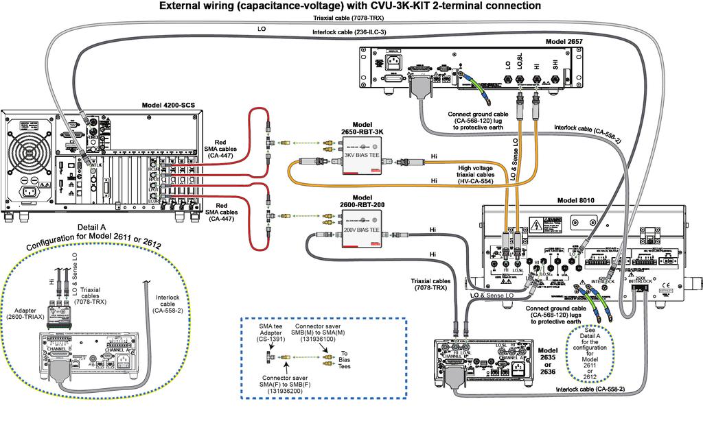
34 CVU-3K-KIT 2-terminal DUT (local sense) Note that this configuration can be used for testing 2-terminal TO-247 devices, too. When testing 2-terminal TO-247 devices make sure to remove the plug from the socket, if inserted; make sure the four axial device terminal posts are disconnected; place the 2-terminal TO-247 device into the 3-pin socket.

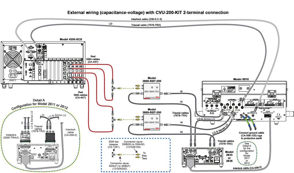
35 CVU-200-KIT 2-terminal DUT (local sense)

36
Model 8020-KHV. Kelvin Keithley Triaxial Connector Card. Description / October 2014 *P * 1
 Keithley Instruments 28775 Aurora Road Cleveland, Ohio 44139 1-800-935-5595 http://www.keithley.com Model 8020-KHV Kelvin Keithley Triaxial Connector Card Description The Model 8020-KHV Keithley HV Connector
Model 2600B-PM V Protection Module with 1 A Clamp. Description / April 2015 *PPA * 1
 Keithley Instruments 28775 Aurora Road Cleveland, Ohio 44139 1-800-935-5595 http://www.keithley.com Model 2600B-PM-1 200 V Protection Module with 1 A Clamp Description The Model 2600B-PM-1 200 V Protection
Model 8020-STC. Kelvin Standard Triaxial Connector Card. Description / October 2014 *P * 1
 Keithley Instruments 28775 Aurora Road Cleveland, Ohio 44139 1-800-935-5595 http://www.keithley.com Model 8020-STC Kelvin Standard Triaxial Connector Card Description The Model 8020-STC Kelvin Standard
Model 2657A-LIM-3 LO Interconnect Module
 Keithley Instruments, Inc. 28775 Aurora Road Cleveland, Ohio 44139 1-888-KEITHLEY http://www.keithley.com Model 2657A-LIM-3 LO Interconnect Module User's Guide Description The Model 2657A-LIM-3 LO Interconnect
Models 2601B, 2602B, and 2604B System SourceMeter Instruments Quick Start Guide
 Models 2601B, 2602B, and 2604B System SourceMeter Instruments Quick Start Guide Safety precautions Observe the following safety precautions before using this product and any associated instrumentation.
Model 2460-KIT. Screw Terminal Connector Kit. Description / September 2014 *P * 1
 Keithley Instruments 28775 Aurora Road Cleveland, Ohio 44139 1-800-935-5595 http://www.keithley.com Model 2460-KIT Screw Terminal Connector Kit Description The Model 2460-KIT Screw Terminal Connector Kit
CVU-200-KIT. 200 V Bias Tee Kit. Description. Parts list / October 2014 *P A* 1
 Keithley Instruments 28775 Aurora Road Cleveland, Ohio 44139 1-800-935-5595 http://www.keithley.com CVU-200-KIT 200 V Bias Tee Kit Description The CVU-200-KIT Bias Tee Kit consists of three 2600-RBT-200
CVU-3K-KIT. 3 kv Bias Tee Kit. Description. Parts list / October 2014 *P * 1
 Keithley Instruments 28775 Aurora Road Cleveland, Ohio 44139 1-800-935-5595 http://www.keithley.com CVU-3K-KIT 3 kv Bias Tee Kit Description The CVU-3K-KIT Bias Tee Kit consists of three bias tees for
This 4200-RM Rack Mount Kit is for installation in 4200-CAB series cabinets only.
 Keithley Instruments, Inc. 28775 Aurora Road Cleveland, Ohio 44139 (440) 248-0400 Fax: (440) 248-6168 www.keithley.com Model 4200-RM Rack Mount Kit Packing List Introduction NOTE This 4200-RM Rack Mount
Model 7705 Control Module
 www.keithley.com Model 7705 Control Module User s Guide PA-696 Rev. D / October 2006 A G R E A T E R M E A S U R E O F C O N F I D E N C E Safety Precautions The following safety precautions should be
Series 370 S SoftwSystem are Qui Switch/Mult ck Start G imeter uide Quick Start Guide
 Series ACS 3700A Software System Quick Switch/Multimeter Start Guide Quick Start Guide Safety precautions Observe the following safety precautions before using this product and any associated instrumentation.
HV-CS kv Edge Mount Triaxial Jack
 Keithley Instruments 28775 Aurora Road Cleveland, Ohio 44139 1-800-935-5595 http://www.tek.com/keithley HV-CS-1589 3 kv Edge Mount Triaxial Jack Installation Information Description The Keithley Instruments
2260B-RMK-Series Rack Mount Kit
 Keithley Instruments, Inc. 28775 Aurora Road Cleveland, Ohio 44139 1-888-KEITHLEY http://www.keithley.com Assembly and Mounting Instructions Introduction The 2260B-RMK-Series Rack Mount Kit is suited for
Model 4200-CVU-PWR. Parts Package. Introduction. PA-977 Rev. C / September 2016 *PPA-977C* 1
 Keithley Instruments 28775 Aurora Road Cleveland, Ohio 44139 1-800-935-5595 http://www.tek.com/keithley Model 4200-CVU-PWR Parts Package Introduction The Model 4200-CVU-PWR C-V Power Package for both the
Model 2380 Rack-Mount Kit
 Keithley Instruments 28775 Aurora Road Cleveland, Ohio 44139 1-800-935-5595 http://www.tek.com/keithley Model 2380 Rack-Mount Kit Installation Instructions Introduction The Model 2380 Fixed Rack-Mount
Startup Software Quick Start Guide
 Startup Software Quick Start Guide Safety precautions Observe the following safety precautions before using this product and any associated instrumentation. Although some instruments and accessories would
Model 2380 Rack-Mount Kit
 Keithley Instruments 28775 Aurora Road Cleveland, Ohio 44139 1-800-935-5595 http://www.tek.com/keithley Model 2380 Rack-Mount Kit Installation Instructions Introduction The Model 2380 Fixed Rack-Mount
Safety Precautions A good safety practice is to expect that hazardous voltage is present in any unknown circuit before measuring.
 Safety Precautions The following safety precautions should be observed before using this product and any associated instrumentation. Although some instruments and accessories would normally be used with
Model GHz 50 Ohm RF Module
 Keithley Instruments 28775 Aurora Road Cleveland, Ohio 44139 1-800-935-5595 tek.com/keithley Model 7711 2 GHz 50 Ohm RF Module Instructions for use with DAQ6510 Introduction The 7711 plug-in module provides
Models 2634B, 2635B, and 2636B System SourceMeter Instruments Quick Start Guide
 Models 2634B, 2635B, and 2636B System SourceMeter Instruments Quick Start Guide Safety Introduction Safety precautions The following safety precautions should be observed before using this product and
Model 7701 Multiplexer Module
 Keithley Instruments 28775 Aurora Road Cleveland, Ohio 44139 1-800-935-5595 tek.com/keithley Model 7701 Multiplexer Module Instructions for use with DAQ6510 Introduction The 7701 32-Channel High-Speed
Models 2601B, 2602B, and 2604B System SourceMeter Instruments Quick Start Guide
 Models 2601B, 2602B, and 2604B System SourceMeter Instruments Quick Start Guide Safety precautions The following safety precautions should be observed before using this product and any associated instrumentation.
Model Channel High Voltage Multiplexer Card
 User s Manual 3762-900-01 Rev. A / July 2017 www.tek.com/keithley Model 3762 10-Channel High Voltage Multiplexer Card *P3762-900-01A* 3762-900-01A Model 3762 10-Channel High Voltage Multiplexer Card User's
Series 2600A System SourceMeter
 www.keithley.com Series 2600A System SourceMeter Quick Start Guide 2600AS-903-01 Rev. A / September 2008 A G R E A T E R M E A S U R E O F C O N F I D E N C E WARRANTY Keithley Instruments, Inc. warrants
Models 707B and 708B Switching Matrix
 E C N E D I F N O C F O E R U S A E M R E T A E R G A Models 707B and 708B Switching Matrix User s Manual 707B-900-01 Rev. A / August 2010 Test Equipment Depot - 800.517.8431-99 Washington Street Melrose,
2281S Precision DC Supply and Battery Simulator Quick Start Guide
 2281S Precision DC Supply and Battery Simulator Quick Start Guide Safety precautions Observe the following safety precautions before using this product and any associated instrumentation. Although some
Model 7700 Multiplexer Module
 Keithley Instruments 28775 Aurora Road Cleveland, Ohio 44139 1-800-935-5595 tek.com/keithley Model 7700 Multiplexer Module Instructions for use with DAQ6510 Introduction The 7700 20-Channel Differential
S530 Parametric Test System
 www.tek.com/keithley S530 Parametric Test System Diagnostic and Verification Manual S530-906-01 Rev. F / September 2017 *PS530-906-01G* S530-906-01G A Tektronix Company S530 Diagnostic and Verification
Model 2440 Service Manual Rev. B / December 2004
 www.keithley.com Model 2440 Service Manual 2440-902-01 Rev. B / December 2004 A G R E A T E R M E A S U R E O F C O N F I D E N C E WARRANTY Keithley Instruments, Inc. warrants this product to be free
Model 2450 Interactive SourceMeter Instrument
 Model 2450 Interactive SourceMeter Instrument Calibration Manual 2450-905-01 Rev. A / June 2014 www.keithley.com *P245090501A* 2450-905-01 A Greater Measure Of Confidence A Tektr onix Company Model 2450
Model 8101-PIV Test Fixture User s Guide. Overview. SMU Device holder (near latch) Two Leaded Part Plungers. PIV Device holder (near hinge)
 Two Leaded Part Plungers. PIV Device holder (near hinge)") Keithley Instruments, Inc. 28775 Aurora Road Cleveland, Ohio 44139 1-888-KEITHLEY www.keithley.com Model 8101-PIV Test Fixture User s uide Overview WARNIN The procedures contained in this User s uide are
Keithley Instruments, Inc. 28775 Aurora Road Cleveland, Ohio 44139 1-888-KEITHLEY www.keithley.com Model 8101-PIV Test Fixture User s uide Overview WARNIN The procedures contained in this User s uide are
Model DAQ6510 Quick Start Guide
 Model DAQ6510 Quick Start Guide Safety precautions The following safety precautions should be observed before using this product and any associated instrumentation. Although some instruments and accessories
Keithley Instruments Customer Documentation Series 2600A UL Safety Supplement
 Keithley Instruments, Inc. 28775 Aurora Road Cleveland, Ohio 44139 1-888-KEITHLEY www.keithley.com Keithley Instruments Customer Documentation Series 2600A UL Safety Supplement 1. Introduction The Keithley
Model 2700 Multimeter/Data Acquisition System Service Manual
 Model 2700 Multimeter/Data Acquisition System Service Manual 2015, Keithley Instruments All rights reserved. Cleveland, Ohio, U.S.A. Third Printing, August 2015 Document Number: 2700-902-01 Rev. C Manual
KPXI 3U Instrument Chassis
 www.keithley.com KPXI 3U Instrument Chassis User s Manual KPXI-SYS-900-01 Rev. A / January 2007 A G R E A T E R M E A S U R E O F C O N F I D E N C E WARRANTY Keithley Instruments, Inc. warrants this product
Mini Digital Multimeter
 User Manual Mini Digital Multimeter Model MN15A Additional User Manual Translations available at www.extech.com Introduction Congratulations on your purchase of the Extech MN15A MultiMeter. The MN15A offers
User Manual. 400Amp AC Clamp Meter + NCV. Model MA430. Additional User Manual Translations available at
 User Manual 400Amp AC Clamp Meter + NCV Model MA430 Additional User Manual Translations available at www.extech.com Introduction Congratulations on your purchase of this Extech MA430 Clamp Meter. This
Model kw Pulse Mode Interactive
 Model 2461 1 kw Pulse Mode Interactive SourceMeter Instrument User s Manual 2461-900-01 Rev. A / November 2015 Test Equipment Depot - 800.517.8431-99 Washington Street Melrose, MA 02176 - TestEquipmentDepot.com
Agilent 16442B. User s Guide. Agilent Technologies
 Agilent 16442B Test Fixture User s Guide Agilent Technologies Notices Agilent Technologies 2002, 2006 No part of this manual may be reproduced in any form or by any means (including electronic storage
User Guide True RMS Multimeter Extech EX205T
 User Guide Extech EX205T True RMS Digital Multimeter Extech EX210T True RMS Digital Multimeter IR True RMS Multimeter Extech EX205T Introduction Thank you for selecting the Extech EX205T True RMS Auto-ranging
Series 3700 System Switch/Multimeter
 www.keithley.com Series 3700 System Switch/Multimeter Quick Start Guide 3700S-903-01 Rev. C / November 2008 A G R E A T E R M E A S U R E O F C O N F I D E N C E WARRANTY Keithley Instruments, Inc. warrants
DM-918 OPERATIONS MANUAL AUTORANGING MULTIMETER
 DM-918 OPERATIONS MANUAL AUTORANGING MULTIMETER SAFETY INFORMATION The following safety information must be observed to ensure maximum personal safety during the operation of this meter: This meter is
USER MANUAL. Mini Multimeter with Non-Contact Voltage Detector (NCV) Model EX310
 Model EX310") USER MANUAL Mini Multimeter with Non-Contact Voltage Detector (NCV) Model EX310 Introduction Congratulations on your purchase of the Extech EX310 MultiMeter. The EX310 offers AC/DC Voltage, AC/DC Current,
USER MANUAL Mini Multimeter with Non-Contact Voltage Detector (NCV) Model EX310 Introduction Congratulations on your purchase of the Extech EX310 MultiMeter. The EX310 offers AC/DC Voltage, AC/DC Current,
Model 2701 Ethernet-Based DMM / Data Acquisition System
 www.keithley.com Model 2701 Ethernet-Based DMM / Data Acquisition System Instrument Networking Instruction Manual 2701-904-01 Rev. C / October 2008 A G R E A T E R M E A S U R E O F C O N F I D E N C E
Mini Digital Multimeter
 User's Guide Mini Digital Multimeter Model MN15 99 Washington Street Melrose, MA 02176 Phone 781-665-1400 Toll Free 1-800-517-8431 Visit us at www.testequipmentdepot.com Back to the Extech MN15/MN16 Series
User's Guide. Digital Multimeter. Model MN42
 User's Guide Digital Multimeter Model MN42 Introduction Congratulations on your purchase of the Extech MN42 MultiMeter. The MN42 offers AC/DC Voltage, DC Current, and Resistance testing. Proper use and
PCT2000. User Manual. Precision current transducer 2000 A
 PCT2000 User Manual PCT2000 Precision current transducer 2000 A User Manual Status: November 6, 2018 Copyright 2018 ZES ZIMMER Electronic Systems GmbH Pfeiffstraße 12 61440 Oberursel (Taunus), Germany
P5200A Series High Voltage Differential Probes. Installation and Safety Instructions & Product Documentation CD
 xx P5200A Series High Voltage Differential Probes ZZZ Installation and Safety Instructions & Product Documentation CD *P071288902* 071-2889-02 Copyright Tektronix. All rights reserved. Licensed software
374 FC/375 FC/376 FC. Clamp Meter. Safety Information
 374 FC/375 FC/376 FC Clamp Meter Safety Information 3-Year Limited Warranty. Go to www.fluke.com to register your Product, read the Users Manual, and find more information. A Warning identifies conditions
38 MHz Passive Voltage Probe R&S RT-ZP1X
 Manual 38 MHz Passive Voltage Probe R&S RT-ZP1X 1333.1370.02 Printed in Germany Test and Measurement 2 Manufacturer ROHDE & SCHWARZ For comprehensive information about Rohde and Schwarz, please visit our
Autoranging True RMS Multimeter User Manual
 Autoranging True RMS Multimeter User Manual Please read this manual before switching the unit on. Important safety information inside. Contents Page 1. Safety Information... 4 2. Safety Symbols... 5 3.
Agilent 34401A 6½ 桁マルチメータ ユーザーガイド
 Agilent 34401A 6½ 桁マルチメータ ユーザーガイド Safety Information General Do not use this product in any manner not specified by the manufacturer. The protective features of this product may be impaired if it is used
Owner's Manual. True RMS Multimeter. Model No Safety Operation Maintenance Español
 Owner's Manual True RMS Multimeter Model No. 82023 CAUTION: Read, understand and follow Safety Rules and Operating Instructions in this manual before using this product. Safety Operation Maintenance Español
Part No. Z , IA Nov OPERATION MANUAL. High Voltage Digitalmeter A
 Part No. Z1-109-920, IA001723 Nov. 2005 OPERATION MANUAL High Voltage Digitalmeter 149-30A Use of Operation Manual Please read through and understand this Operation Manual before operating the product.
MDM 011-Z1 Regen Resistor
 MDM 011-Z1 Regen Resistor Date of creation: 10.04.2017 Version date: 10.04.2017 Article number: 09-402-011-Z1-E Publisher: SIGMATEK GmbH & Co KG A-5112 Lamprechtshausen Tel.: 06274/4321 Fax: 06274/4321-18
OPERATING INSTRUCTION
 OPERATING INSTRUCTION AUTORANGING MULTIMETER MAX Ω F C 10A MAX every 15 min. COM V SAFETY INFORMATION The following safety information must be observed to insure maximum personal safety during the operation
POCKET MULTIMETER Model No: MM18
 INSTRUCTIONS FOR: POCKET MULTIMETER Model No: MM18 Thank you for purchasing a Sealey product. Manufactured to a high standard this product will, if used according to these instructions and properly maintained,
Obtaining Documentation and Submitting a Service Request, page xvii Safety Warnings, page xvii Safety Guidelines, page xx
 Preface Obtaining Documentation and Submitting a Service Request, page xvii Safety s, page xvii Safety Guidelines, page xx Obtaining Documentation and Submitting a Service Request For information on obtaining
Part No. Z , IA Mar OPERATION MANUAL. High Voltage Digitalmeter A
 Part No. Z1-109-820, IA001704 Mar. 2011 OPERATION MANUAL High Voltage Digitalmeter 149-10A Use of Operation Manual Please read through and understand this Operation Manual before operating the product.
Model /2-Digit Resolution Digital Multimeter
 www.keithley.com Model 2100 6 1/2-Digit Resolution Digital Multimeter User s Manual 2100-900-01 Rev. D / September 2011 A G R E A T E R M E A S U R E O F C O N F I D E N C E Model 2100 6 ½-Digit Resolution
Model P4017 Single Channel USB Oscilloscope. Quick Start Guide
 Model P4017 Single Channel USB Oscilloscope Quick Start Guide General Warranty BNC warrants that the product will be free from defects in materials and workmanship for 3 years from the date of purchase
Emerson Network Power provides customers with technical support. Users may contact the nearest Emerson local sales office or service center.
 Liebert PSA iton User Manual Version: V2.8 Revision date: November 14, 2005 Emerson Network Power provides customers with technical support. Users may contact the nearest Emerson local sales office or
Digital ac/dc (24V) Input Module
 Input Module") Installation Instructions Digital ac/dc (24V) Input Module Catalog Number 1771-IND, Series C Topic Page Important User Information 2 Before You Begin 3 Power Requirements 3 Prevent Electrostatic Discharge
Installation Instructions Digital ac/dc (24V) Input Module Catalog Number 1771-IND, Series C Topic Page Important User Information 2 Before You Begin 3 Power Requirements 3 Prevent Electrostatic Discharge
Model 2001 Multimeter
 www.keithley.com Model 2001 Multimeter Calibration Manual 2001-905-01 Rev. G / May 2004 A G R E A T E R M E A S U R E O F C O N F I D E N C E Model 2001 Multimeter Calibration Manual 1992, Keithley Instruments,
Mini Digital Multimeter Model MN15. User's Guide
 Mini Digital Multimeter Model MN15 User's Guide Introduction Congratulations on your purchase of the Extech MN15 MultiMeter. The MN15 offers AC/DC Voltage, AC/DC Current, Resistance, Diode, and Continuity
1-36V, 0-3A DC Power Supply
 1550 1-36V, 0-3A DC Power Supply User Manual Safety Summary The following safety precautions apply to both operating and maintenance personnel and must be followed during all phases of operation, service,
Model 2000-SCAN Scanner Card
 www.keithley.com Model 2000-SCAN Scanner Card Instruction Manual 2000-SCAN-901-01 Rev. F / February 2014 *P2000SCAN90101F* 2000-SCAN-901-01F A Greater Measure of Confidence Model 2000-SCAN Scanner Card
Installing and Configuring Rialto Analytic Appliances
 Installing and Configuring Rialto Analytic Appliances Important Safety Information This manual provides installation and operation information and precautions for the use of this camera. Incorrect installation
AutoRanging Digital MultiMeter
 Owner's Manual AutoRanging Digital MultiMeter Model No. 82175 CAUTION: Read, understand and follow Safety Rules and Operating Instructions in this manual before using this product. Safety Operation Maintenance
Line Impedance Stabilization Network (LISN)
") Model 3816/2 Line Impedance Stabilization Network (LISN) User Manual ETS-Lindgren Inc. reserves the right to make changes to any product described herein in order to improve function, design, or for any
Model 3816/2 Line Impedance Stabilization Network (LISN) User Manual ETS-Lindgren Inc. reserves the right to make changes to any product described herein in order to improve function, design, or for any
ETHOS Auto Ranging Digital Multimeter
 ETHOS 5020 Auto Ranging Digital Multimeter 1 1. SAFETY INFORMATION SAFETY SYMBOLS Warning! Dangerous Voltage (Risk of electric shock). Caution! Refer to the user s manual before using this Meter. Double
Autoranging Mini Multimeter
 User Manual Autoranging Mini Multimeter Model MN16A Additional User Manual Translations available at www.extech.com Introduction Congratulations on your purchase of the Extech MN16A Autoranging Multimeter.
Mini Digital Multimeter
 User's Guide Mini Digital Multimeter Model MN15 Introduction Congratulations on your purchase of the Extech MN15 MultiMeter. The MN15 offers AC/DC Voltage, AC/DC Current, Resistance, Diode, and Continuity
High Voltage Power Supplies
 Source voltages up to 5kV and 10kV 1µA current measurement resolution Multi-channel programmable DC power supplies Low noise for precision sourcing and sensitive measurements; selectable filters reduce
User's Guide. MiniTec TM Series Model MN25 MultiMeter
 User's Guide MiniTec TM Series Model MN25 MultiMeter Warranty EXTECH INSTRUMENTS CORPORATION warrants this instrument to be free of defects in parts and workmanship for one year from date of shipment (a
The following symbols are used to show dangerous operation or handling. Make sure you understand them before reading the guide.
 Safety Instructions Before use Thank you very much for purchasing this product. This product is an interface box called "Connection & Control Box" for EPSON short throw projectors. For your safety, read
Part No. Z , IA Jul OPERATION MANUAL. High Voltage Digitalmeter A
 Part No. Z1-109-820, IA001705 Jul. 2016 OPERATION MANUAL High Voltage Digitalmeter 149-10A Use of Operation Manual Please read through and understand this Operation Manual before operating the product.
* * Agilent Power Distribution Unit (PDU) Installation Guide
 Installation Guide") Agilent Power Distribution Unit (PDU) Installation Guide For use with Agilent PDU kits and PDU installation kits for Agilent instrument racks June 2008 Edition 7 E0608 *5000-0039* 5000-0039 Notice The
Agilent Power Distribution Unit (PDU) Installation Guide For use with Agilent PDU kits and PDU installation kits for Agilent instrument racks June 2008 Edition 7 E0608 *5000-0039* 5000-0039 Notice The
Model 2010 Multimeter Service Manual Rev. D / October 2003
 www.keithley.com Model 2010 Multimeter Service Manual 2010-902-01 Rev. D / October 2003 A G R E A T E R M E A S U R E O F C O N F I D E N C E WARRANTY Keithley Instruments, Inc. warrants this product to
MARTINDALE INSTRUCTIONS MM35 DIGITAL MULTIMETER ELECTRIC. Trusted by professionals
 Martindale Electric will carry out routine calibration (on a chargeable basis) if the instrument is returned, carriage paid, to the address on the final page of this document. Alternatively, a chargeable
TETRIS 2500 High Impedance Active Probe. Instruction Manual
 TETRIS 2500 High Impedance Active Probe Instruction Manual Copyright 2018 PMK GmbH All rights reserved. Information in this publication supersedes that in all previously published material. Specifications
9040/9040UK. Users Manual. Phase Rotation Indicator
 9040/9040UK Phase Rotation Indicator Users Manual PN 2438546 April 2005 2005 Fluke Corporation. All rights reserved. Printed in China All product names are trademarks of their respective companies. LIMITED
S-14 S-14. Compact Digital Multimeter. Compact Digital Multimeter
 S-14 Compact Digital Multimeter S-14 Compact Digital Multimeter SAFETY INFORMATION The following safety information must be observed to insure maximum personal safety during the operation at this meter
Model INSTRUCTION MANUAL DIGITAL MULTIMETER
 Model 57040 INSTRUCTION MANUAL DIGITAL MULTIMETER SAFETY INFORMATION This multimeter has been designed according to IEC 1010 concerning electronic measuring instruments with an overvoltage category (CAT
User s Guide. 600A True RMS AC/DC Clamp Meter. Model 38389
 User s Guide 600A True RMS AC/DC Clamp Meter Model 38389 Safety International Safety Symbols This symbol, adjacent to another symbol or terminal, indicates the user must refer to the manual for further
Model 9140A-PCA Probe Card Adapter
 www.tek.com/keithley Model 9140A-PCA Probe Card Adapter Instructions 9140A-PCA-901-01 Rev. B / December 2017 *P9140A-PCA-901-01B* 9140A-PCA-901-01B A Tektronix Company Model 9140A-PCA Probe Card Adapter
HI-POT TESTER User Manual
 HI-POT TESTER 7600 User Manual Contents 1. Safety...- 3-1.1 General...- 3 - AC Power Supply...- 4-1.2 Adjustment, Maintenance and Repair...- 5-1.3 Static Electricity...- 5-2. General:...- 6-2.1Packing
OPERATING MANUAL FOR THE 30KV A.C. TEST SET P123. Bicotest High Voltage Products Ltd
 OPERATING MANUAL FOR THE 30KV A.C. TEST SET P123 Product: High Voltage AC Test Set Type: P123 Bicotest High Voltage Products Ltd Hellesdon Park Road, Drayton High Road, Norwich NR6 5DR United Kingdom Phone
DM3058/DM3058E Digital Multimeter
 Quick Guide RIGOL Publication number QGA03109-1110 Feb. 2014 DM3058/DM3058E Digital Multimeter 2008 RIGOL Technologies, Inc. All Rights Reserved Copyright 2008 RIGOL Technologies, Inc. All Rights Reserved.
Variable-Speed Vortex Mixer
 Variable-Speed Vortex Mixer User Guide Version 1.1 IEC connector Retort rod fitting Rubber cup Speed control dial Power on/off button Mode button Figure 1: Vortex Mixer Figure 2: Front panel 2 Variable-Speed
Installation Job Aid for Ethernet Routing Switch 3600 Series
 Installation Job Aid for Ethernet Routing Switch 3600 Series Notices NN47213-303 Issue 03.01 November 2017 Notice paragraphs alert you about issues that require your attention. Following are descriptions
Model DAQ6510 Data Acquisition and Multimeter System
 User s Manual DAQ6510-900-01 Rev. A / April 2018 tek.com/keithley Model DAQ6510 Data Acquisition and Multimeter System *PDAQ6510-900-01A* DAQ6510-900-01A DAQ6510 Data Acquisition / Multimeter System User's
User's Guide. Extech AM A AC Analog Clamp Meter
 User's Guide Extech AM300 300A AC Analog Clamp Meter Introduction Congratulations on your purchase of the Extech AM300 Analog Clamp Meter. This device measure AC Voltage and Current, DC Voltage, and Resistance.
EPS Power Supply
 EPS - 600 Power Supply Installation and Operation Manual Version 1.0 *This instrument is intended for laboratory use only Index A. Important Notice ----------------------------------------------------------------
MC 11 EB-2 Power supply cabinet with external bus, AC version
 MC 11 EB-2 Power supply cabinet with external bus, AC version USER/MAINTENANCE MANUAL 1 SLOT 0 SLOT 1 SLOT 2 SLOT 3 SLOT 4 SLOT 5 SLOT 6 SLOT 7 SLOT 8 SLOT 9 SLOT 10 SLOT 11 EB-2 (a) MC11 (b) (c) Figures
DS1000B Series Digital Oscilloscope
 Quick Guide RIGOL Publication number QGA04114-1110 Feb. 2014 DS1000B Series Digital Oscilloscope DS1074B, DS1104B, DS1204B All Rights Reserved Copyright All Rights Reserved. RIGOL products are protected
INSTRUCTION MANUAL. * Design and Specifications are subject to change without notice. ver. 1.0 PRINTED IN KOREA
 INSTRUCTION MANUAL * Design and Specifications are subject to change without notice. ver. 1.0 PRINTED IN KOREA INSTRUCTION MANUAL Thank you for purchasing this product. For proper usage and application,
CS2 DMX Distribution Splitter
 CS2 DMX Distribution Splitter User Manual Order code: BOTE72 Safety advice WARNING FOR YOUR OWN SAFETY, PLEASE READ THIS USER MANUAL CAREFULLY BEFORE YOUR INITIAL START-UP! Before your initial start-up,
Installation Job Aid for VSP 4450GTX-HT- PWR+
 Installation Job Aid for VSP 4450GTX-HT- PWR+ Notices Release 6.1.0.0 NN46251-305 Issue 02.01 November 2017 Notice paragraphs alert you about issues that require your attention. The following paragraphs
2016 SIGLENT TECHNOLOGIES CO.,LTD
 Quick Strat SDM3045X Digital Multimeter QS06034-E01A 2016 SIGLENT TECHNOLOGIES CO.,LTD Copyright Information SIGLENT TECHNOLOGIES CO., LTD. All rights reserved. The information provided in this manual