User Guide VLT Parallel Drive Modules
|
|
|
- Milton Nicholson
- 5 years ago
- Views:
Transcription


1 ENGINEERING TOMORROW User Guide VLT Parallel Drive Modules kw vlt-drives.danfoss.com
2
3 Contents User Guide Contents 1 Introduction Purpose of the Manual Additional Resources Manual and Software Version Approvals and Certifications Disposal 4 2 Safety Safety Symbols Qualified Personnel Safety Precautions 5 3 Product Overview Intended Use Drive System Drive Module Control Shelf 13 4 Commissioning Safety Instructions Applying Power Local Control Panel (LCP) Overview Layout Menus Programming the Drive System Entering System Information Q3 Function Set-ups Control Terminal Programming Configuring Automatic Energy Optimization Configuring Automatic Motor Adaptation Testing Before System Startup Motor Rotation Encoder Rotation Local Control Test System Startup Parameter Settings Uploading and Downloading Parameter Settings Restoring Factory Default Settings 21 MG37L202 Danfoss A/S 08/2017 All rights reserved. 1
4 Contents VLT Parallel Drive Modules 5 Application Set-up Examples Introduction Application Examples Automatic Motor Adaptation (AMA) RS485 Network Connection Smart Logic Controller (SLC) Mode Mechanical Brake Control Open Loop Speed Control Start/Stop External Alarm Reset Motor Thermistor Connection Examples for Control of Motor with External Signal Provider Start/Stop Pulse Start/Stop Speed Up/Down Potentiometer Reference 30 6 Maintenance, Diagnostics, and Troubleshooting Maintenance and Service Periodic Maintenance Status Messages Warning and Alarm Types List of Warnings and Alarms Warnings/Alarm Messages Troubleshooting Running in Reduced Power Mode Safety Configuring the Drive System for Reduced Power Mode Wiring Configurations 53 7 Specifications Power-dependent Specifications VLT HVAC Drive FC VLT AQUA Drive FC VLT AutomationDrive FC Connection Tightening Torques Fuses and Circuit Breakers Protection Fuse Selection Recommended Fuses for CE Compliance 69 2 Danfoss A/S 08/2017 All rights reserved. MG37L202
5 Contents User Guide Recommended Fuses for UL Compliance Fuse Replacement Short Circuit Current Rating (SCCR) 70 8 Appendix Symbols, Abbreviations, and Conventions International/North American Default Parameter Settings Parameter Menu Structure Main Menu Structure 73 Index 77 MG37L202 Danfoss A/S 08/2017 All rights reserved. 3
6 Introduction VLT Parallel Drive Modules 1 1 Introduction 1.1 Purpose of the Manual This manual provides detailed information for startup and commissioning of the drive system composed of VLT Parallel Drive Modules. Chapter 4 Commissioning provides detailed procedures for basic programming, pre-startup testing, and startup. The remaining chapters provide supplementary details, including: The user interface. Detailed programming. Application examples. Operational troubleshooting. Specifications. This user guide is intended for use by qualified personnel. To operate and maintain the drive system safely and professionally, read and follow the user guide. Pay particular attention to the safety instructions and general warnings. Always keep this user guide with the drive system. VLT is a registered trademark. 1.2 Additional Resources Other resources are available to understand the functions and programming of the VLT Parallel Drive Modules. The VLT Parallel Drive Modules DC Fuses Installation Instructions contain detailed information about installing the DC fuses. The VLT Parallel Drive Modules Bus Bar Kit Installation Instructions contain detailed information about installing the busbar option kit. The VLT Parallel Drive Modules Duct Kit Installation Instructions contain detailed information about installing the duct option kit. Refer to other supplemental publications and manuals, available from Danfoss. See vlt-drives.danfoss.com/support/ technical-documentation/ for listings. 1.3 Manual and Software Version This manual is regularly reviewed and updated. All suggestions for improvement are welcome. Table 1.1 shows the manual version and the corresponding software version. Manual version MG37L2xx Remarks Update to Drive System section Table 1.1 Manual and Software Version 1.4 Approvals and Certifications Software version FC 102 (5.0x), FC 202 (3.0x), FC 302 (7.6x) The VLT Parallel Drive Modules kw Design Guide contains detailed information about the capabilities and functionality of motor control systems using these drive modules, and provides guidance for designing this type of system. The VLT Parallel Drive Modules kw Installation Guide provides instructions for mechanical and electrical installation of these drive modules. Refer to the FC 102, FC 202, or FC 302 VLT Drive Programming Guide applicable to the particular series of VLT Parallel Drive Modules used in creating the drive system. The programming guide describes in greater detail how to work with parameters and provides application examples. The VLT FC Series, D-frame Service Manual contains detailed service information, including information applicable to the VLT Parallel Drive Modules. Table 1.2 Approvals 1.5 Disposal Do not dispose of equipment containing electrical components together with domestic waste. Collect it separately in accordance with local and currently valid legislation. 4 Danfoss A/S 08/2017 All rights reserved. MG37L202
7 Safety User Guide 2 Safety 2.1 Safety Symbols The following symbols are used in this manual: WARNING Indicates a potentially hazardous situation that could result in death or serious injury. CAUTION Indicates a potentially hazardous situation that could result in minor or moderate injury. It can also be used to alert against unsafe practices. NOTICE Indicates important information, including situations that can result in damage to equipment or property. 2.2 Qualified Personnel Correct and reliable operation and maintenance are required for the trouble-free and safe operation of the drive system. Only qualified personnel are allowed to operate and maintain this equipment. Qualified personnel are defined as persons who are trained and authorized to commission, operate, and maintain equipment, systems, and circuits in accordance with pertinent laws and regulations. Also, the personnel must be familiar with the instructions and safety measures described in this manual. 2.3 Safety Precautions WARNING HIGH VOLTAGE The drive system contains high voltage when connected to AC mains input. Failure to ensure that only qualified personnel are allowed to operate and maintain the system can result in death or serious injury. WARNING UNINTENDED START When the drive system is connected to AC mains, the motor can start at any time. Unintended start during programming, service, or repair work can result in death, serious injury, or property damage. The motor can start via any of the following: An external switch. A fieldbus command. An input reference signal from the LCP. A cleared fault condition. Remote operation using MCT 10 software. To prevent unintended motor start: Disconnect the drive system from AC mains. Press [Off/Reset] on the LCP, before programming parameters. The drive system, motor, and any driven equipment must be fully wired and assembled when the drive is connected to AC mains. WARNING DISCHARGE TIME The drive system contains DC-link capacitors. Once mains power has been applied to the drive system, these capacitors can remain charged even after the power has been removed. High voltage can be present even when the warning indicator lights are off. Failure to wait 20 minutes after power has been removed before performing service or repair work can result in death or serious injury. Stop the motor. Disconnect AC mains and remote DC-link power supplies, including battery back-ups, UPS, and DC-link connections to other drives. Disconnect or lock the PM motor. Check the system for an installed external discharge resistor. If a discharge resistor is installed, activate its associated contactor. Before servicing the drive system, use a multimeter to verify that the DC voltage on each drive module is fully discharged. If an external discharge resistor is not installed, wait 20 minutes for the capacitors to discharge fully before performing any service or repair work. 2 2 MG37L202 Danfoss A/S 08/2017 All rights reserved. 5
8 Safety VLT Parallel Drive Modules 2 WARNING LEAKAGE CURRENT HAZARD (>3.5 ma) Leakage currents exceed 3.5 ma. Failure to ground the drive system properly can result in death or serious injury. Follow national and local codes regarding protective earthing of equipment with a leakage current >3.5 ma. Frequency converter technology used in the drive system implies high frequency switching at high power. This switching generates a leakage current in the ground connection. A fault current in the drive system at the output power terminals sometimes contains a DC component, which can charge the filter capacitors and cause a transient ground current. The ground leakage current depends on various system configurations including RFI filtering, shielded motor cables, and drive system power. If the leakage current exceeds 3.5 ma, EN/IEC (Power Drive System Product Standard) requires special care. Grounding must be reinforced in 1 of the following ways: Ensure the correct grounding of the equipment by a certified electrical installer. Ground wire of at least 10 mm 2 (7 AWG). Two separate ground wires, both complying with the dimensioning rules. See EN for further information. WARNING EQUIPMENT HAZARD Contact with rotating shafts and electrical equipment can result in death or serious injury. Ensure that only trained and qualified personnel are allowed to perform startup or maintenance. Ensure that electrical work conforms to national and local electrical codes. Follow the procedures in this manual. CAUTION INTERNAL FAILURE HAZARD Missing or incorrectly placed safety covers in the drive system can result in serious injury. Ensure that all safety covers are in place and securely fastened before applying power. WARNING UNINTENDED MOTOR ROTATION WINDMILLING Unintended rotation of permanent magnet motors creates voltage and can charge the capacitors in the drive system, resulting in death, serious injury, or equipment damage. Ensure that permanent magnet motors are blocked to prevent unintended rotation. WARNING DISCONNECT POWER BEFORE SERVICING Sometimes during installation, AC mains power is applied but then must be disconnected to change the line connections. In that case, disconnect the drive system from the AC mains, 230 V supply, and motor lines. After the lines have been disconnected, wait 30 minutes for the capacitors to discharge. Failure to follow these steps can result in death or serious injury. 6 Danfoss A/S 08/2017 All rights reserved. MG37L202
9 Product Overview User Guide 3 Product Overview 3.1 Intended Use A drive system is a type of electronic motor controller that converts AC mains input into a variable AC waveform output. The system then regulates the frequency and voltage of the output to control the motor speed or torque. This drive system is designed by the installer, using the VLT Parallel Drive Modules basic kit and any selected options kits. The basic kit is composed of 2 or 4 drive modules and connecting hardware, and is UL 508 C compliant. 3 3 This drive system can be used in residential, industrial, and commercial environments, in accordance with local laws and standards. NOTICE In a residential environment, this product can cause radio interference, in which case supplementary measures may be required to mitigate the interference. Foreseeable misuse Do not use the drive system in applications that are not compliant with specified operating conditions and environments. Ensure compliance with the conditions specified in chapter 7 Specifications. 3.2 Drive System The drive system is designed by the installer to meet specified power requirements, using the VLT Parallel Drive Modules basic kit and any selected options kits. The basic kit consists of connecting hardware and either 2 or 4 drive modules, which are connected in parallel. NOTICE Illustration 3.1 shows a system using 4 drive modules. A system using 2 drive modules is similar, except for the connecting hardware. Illustration 3.1 shows the busbar option kit. The installer can use other connection methods, including locally manufactured busbars or electrical cables. The installer is responsible for the details of the drive system construction, including connections and proper grounding. MG37L202 Danfoss A/S 08/2017 All rights reserved. 7
10 VLT Parallel Drive Modules 130BE Product Overview Area 1 Title Functions Cabinet (installer-provided) Used to house the drive modules and other drive system components. 2 Drive modules 2 or 4 drive modules can be installed in parallel to create a drive system. 3 Control shelf Consists of an MDCIC (Multi-Drive Control Interface Card), a control card, an LCP, a safety relay, and an SMPS (switched-mode power supply). The MDCIC interfaces the LCP and control card with the power card in each drive module. 4 LCP The local control module, shown mounted on the cabinet door. Allows the operator to monitor and control the system and motor. 5 Protective shields In this view EMI/EMC shields and other protective shields are shown removed so that the parts of the drive system can be made visible. Some of these shields reduce EMI/EMC emissions, while other shields provide physical protection against the high-voltage electrical hazard. Illustration 3.1 Drive System Overview 8 Danfoss A/S 08/2017 All rights reserved. MG37L202
11 Product Overview User Guide Components and their functions Illustration 3.2 provides a functional description of the drive system components. The dashed lines in the diagram represent the option of connecting either 2 or 4 drive modules in parallel. 5 e30be R/ S/ T/ U/ V/ W/ R + R - R/ S/ T/ U/ V/ W/ R + R - R/ S/ T/ U/ V/ W/ R + R - R/ S/ T/ U/ V/ W/ R + R Area Title Functions 1 DC-link terminals and DC fuses These terminals allow access to the DC-link and DC fuses on the individual drive modules. 2 Drive modules This diagram shows a drive system in which 2 drive modules are installed in parallel. In this same fashion, a system can also be constructed with 4 drive modules. See chapter 3.3 Drive Module. 3 Mains input busbars The input terminals of the individual drive modules are connected to the mains input busbars with the use of flexible busbars. By doing so, the input busbars join the input terminals of the individual drive modules in parallel, and provide a connection for the mains input cables to the drive system. The mains input busbars are part of the busbar kit, which can be ordered from Danfoss as an option. However, the installer may choose to fabricate the busbars locally, or use cables in place of busbars. 4 Mains input 3-phase AC mains power input to the drive system, connected to the mains input busbars. In a system using 4 drive modules, the installer must install line wiring to both sets of mains input busbars. MG37L202 Danfoss A/S 08/2017 All rights reserved. 9
12 Product Overview VLT Parallel Drive Modules 3 Area Title Functions 5 DC-link busbars Used to connect the DC-links of the drive modules in parallel. The DC-link busbars are part of the busbar kit, which can be ordered from Danfoss as an option. The kit also includes the required busbar to tie together the 2 sets of DC-link busbars. The installer, however, may choose to fabricate the busbars locally, or use cables in place of busbars. 6 Brake resistor terminals Terminals used to connect an external brake resistor to the drive module. 7 Motor output busbars The output terminals of the individual drive modules are connected to the motor output busbars with the use of flexible busbars. By doing so, the output busbars join the output terminals of the individual drive modules in parallel, and provide a connection to the motor cables to supply controlled AC voltage output to the motor. The motor output busbars are part of the busbar kit, which can be ordered from Danfoss as an option. However, the installer may choose to fabricate the busbars locally, or use cables in place of busbars. 8 Motor output Controlled AC output to the motor. In a system using 4 drive modules, the installer must install an equal number of motor wires to both sets of motor output busbars. Illustration 3.2 Drive System Block Diagram 10 Danfoss A/S 08/2017 All rights reserved. MG37L202
13 Product Overview User Guide 3.3 Drive Module Each drive module has an IP00 protection rating. Either 2 or 4 drive modules can be connected in parallel to create a drive system, based on power requirements. The drive modules are part of the VLT Parallel Drive Modules basic kit, which also includes the control shelf, DC fuses, and wiring harnesses BE Area Title Functions 1 Drive module 2 or 4 drive modules can be used in a drive system, according to the power requirements. 2 Data label Drive module data label. Refer to the VLT Parallel Drive Modules Installation Guide for details. 3 Product label Drive module product label. Refer to the VLT Parallel Drive Modules Installation Guide for details. Illustration 3.3 Drive Module Overview MG37L202 Danfoss A/S 08/2017 All rights reserved. 11
14 Product Overview VLT Parallel Drive Modules 3 Components and their functions Illustration 3.4 provides a functional description of the drive module components. Each drive module contains the following: Input rectifier section. Intermediate DC bus section. Inverter section BE M 8 Illustration 3.4 Drive Module Block Diagram Area Title Functions 1 Mains input 3-phase AC mains power input to the drive module. 2 Input rectifier section Converts mains input AC voltage into DC voltage. 3 Intermediate DC bus section Act as a filter and stores energy in the form of DC voltage. 4 DC reactors The DC reactors: Filter the intermediate DC circuit voltage. Reduce RMS current. Raise the power factor reflected back to the line. Reduce harmonics on the AC input. 5 Capacitor bank Stores the DC power and provides ride-through protection for short power losses. 6 Inverter section Converts the DC voltage into a variable, controlled PWM AC output voltage to the motor. 7 Motor output Output to the motor being controlled. 8 Power card Monitors input and motor current to provide efficient operation and control. Monitors the user interface and performs external commands. Can provide status output and control. In a drive system, a ribbon cable links the power card to the MDCIC on the control shelf. The MDCIC provides supervision over the drive modules in the system. Table 3.1 Single Drive Module - Simplified Block Diagram 12 Danfoss A/S 08/2017 All rights reserved. MG37L202
15 Product Overview User Guide 3.4 Control Shelf The control shelf contains the LCP, MDCIC, and control card. The LCP provides access to the system parameters. The MDCIC is connected to each of the drive modules via a ribbon cable and communicates to the control card. The control card controls the operation of the drive modules BE Control shelf Interfaces with, and controls, the various drive system components. Allows the connection of an external control device. 2 LCP cradle Cradle where the LCP may optionally be installed. 3 Control terminal blocks Terminal blocks for connecting control wiring. 4 Top-level drive system label Label describing the drive system at the top-level. For details, refer to the VLT Parallel Drive Modules Installation Guide. 5 Relay terminal blocks Terminal blocks for connecting the relay cable from the relay connector on the top plate of drive module 1. Illustration 3.5 Control Shelf MG37L202 Danfoss A/S 08/2017 All rights reserved. 13
16 Commissioning VLT Parallel Drive Modules 4 Commissioning Safety Instructions See chapter 2 Safety for general safety instructions. WARNING HIGH VOLTAGE The drive system contains high voltage when connected to AC mains input power, DC supply, or load sharing. Failure to perform installation, startup, and maintenance by qualified personnel can result in death or serious injury. Before applying power: 1. Ensure that input power to the unit is OFF and locked out. Do not rely on the drive system s disconnect switches for input power isolation. 2. Verify that there is no voltage on mains terminals L1 (91), L2 (92), and L3 (93), phase-to-phase, and phase-to-ground. 3. Verify that there is no voltage on motor terminals 96 (U), 97 (V), and 98 (W), phase-to-phase, and phase-to-ground. 4. Confirm continuity of the motor by measuring resistance values on U V (96 97), V W (97 98), and W U (98 96). 5. Check for proper grounding of the drive system and the motor. 6. Inspect the drive system for loose connections on the terminals. 7. Confirm that the supply voltage matches the voltage of the drive system and the motor. 4.2 Applying Power WARNING UNINTENDED START When the drive system is connected to AC mains, the motor can start at any time. Unintended start during programming, service, or repair work can result in death, serious injury, or property damage. The motor can start via any of the following: An external switch. A fieldbus command. An input reference signal from the LCP. A cleared fault condition. Remote operation using MCT 10 Set-up Software. To prevent unintended motor start: Disconnect the drive system from AC mains. Press [Off/Reset] on the LCP, before programming parameters. The drive system, motor, and any driven equipment must be fully wired and assembled when the drive is connected to AC mains. Apply power to the drive system, according to the following steps: 1. Confirm that the input voltage is balanced within 3%. If not, correct the input voltage imbalance before proceeding. Repeat this procedure after the voltage correction. 2. Ensure that the wiring of any optional equipment matches the installation application. 3. Ensure that all operator devices are in the OFF position. 4. Close all panel doors and securely fasten all covers. 5. Apply power to the drive system. DO NOT start the drive system now. For units with a disconnect switch, turn the switch to the ON position to apply power to the drive system. 14 Danfoss A/S 08/2017 All rights reserved. MG37L202
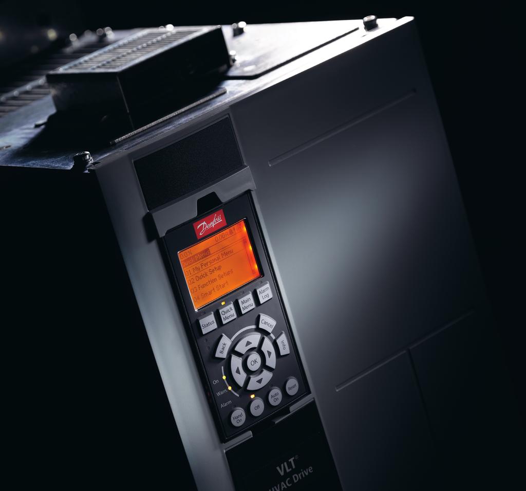
17 Info Commissioning User Guide 4.3 Local Control Panel (LCP) Overview A1.2 A1.1 Status 1(1) 0.0 % 0.00 A 0.00 kw A BD The local control panel (LCP) is a combined display and keypad that allows the operator to monitor and control the system and motor. The LCP is shipped with the VLT Parallel Drive Modules basic kit, mounted on the control shelf. During construction of the panel, the LCP is relocated from the control shelf to the cabinet door, for ease of access. See Illustration 3.1. B1 Off Remote Stop Status Quick Menu 0.0Hz 2605 kwh Main Menu Alarm Log A2 A3 B4 4 4 B2 B3 The LCP has several user functions: Starts, stops, and controls speed when in local control. Shows operational data, status, warnings, and alarms. Programs drive system functions. Manually resets the drive system after a fault when auto reset is inactive. C1 D1 D2 D3 On Warn. Alarm Back OK Cancel C2 C3 C4 C Layout Hand On Off Auto On Reset The LCP is activated when the drive system receives power from 1 of the following: Mains voltage. DC bus terminal. 24 V DC external supply. The LCP is divided into the following 4 functional groups. A. Display area Each display readout has a parameter associated with it. Refer to Illustration 4.1. The default settings shown on the LCP are a function of the type of drive system being configured (VLT HVAC Drive FC 102, VLT AQUA Drive FC 202, or VLT AutomationDrive FC 302). This information can be customized for the application by selecting options in the Quick Menus Q1 My Personal Menu. Callout Parameter number Default settings FC 102 FC 202 FC 302 A Reference % Reference A Motor current [unit] Analog input 53 Speed [RPM] Motor current A Power [kw] Motor current Power [kw] A Frequency Frequency Frequency A kwh counter Feedback [unit] Table 4.1 Legend to Illustration 4.1, LCP Display Area Reference % E1 E2 E3 E4 Illustration 4.1 Local Control Panel (LCP) B. Menu keys Menu keys are used to access the menu for setting up parameters, toggling through status display modes during normal operation, and viewing fault log data. Callout Key Function B1 Status Shows operational information. B2 Quick Menu Allows access to parameters for initial set-up instructions and provides detailed application steps. See chapter 4.4 Programming the Drive System. B3 Main Menu Allows access to all parameters. See chapter 8.3 Parameter Menu Structure. B4 Alarm Log Shows a list of current warnings, the last 10 alarms, and the maintenance log. Table 4.2 Legend to Illustration 4.1, LCP Menu Keys C. Navigation keys Navigation keys are used for programming functions and moving the display cursor. The navigation keys also provide speed control in local (hand) operation. The display brightness can be adjusted by pressing [Status] and [ ]/[ ] keys. MG37L202 Danfoss A/S 08/2017 All rights reserved. 15
18 Commissioning VLT Parallel Drive Modules 4 Callout Key Function C1 Back Reverts to the previous step or list in the menu structure. C2 Cancel Cancels the last change or command as long as the display mode has not changed. C3 Info Shows a definition of the function being shown. C4 OK Accesses parameter groups or enables an option. C5 Moves between items in the menu. Table 4.3 Legend to Illustration 4.1, LCP Navigation Keys D. Indicator lights Indicator lights are used to identify the drive system status and to provide a visual notification of warning or fault conditions. Callout Indicator Indicator light Function D1 On Green Activates when the drive system receives power from the mains voltage or a 24 V external supply. D2 Warn. Yellow Activates when warning conditions are active. Text appears in the display area identifying the problem. D3 Alarm Red Activates during a fault condition. Text appears in the display area identifying the problem. Table 4.4 Legend to Illustration 4.1, LCP Indicator Lights E. Operation keys and reset The operation keys are found toward the bottom of the local control panel. Callout Key Function E1 Hand On Starts the drive system in local control. An external stop signal by control input or serial communication overrides the local hand on. E2 Off Stops the motor but does not remove power to the drive system. E3 Auto On Puts the system in remote operational mode so it can respond to an external start command by control terminals or serial communication. E4 Reset Resets the drive system manually after a fault has been cleared. Table 4.5 Legend to Illustration 4.1, LCP Operation Keys, and Reset Menus Quick Menu Mode The LCP provides access to all parameters listed under the Quick Menus. To show the list of options in the Quick Menu, press [Quick Menu]. 0.0% 0.00 Quick Menus 01 My Personal Menu 02 Quick Setup 05 Changes Made 06 Loggings Illustration 4.2 Quick Menu View Q1 My Personal Menu 1(1) The Personal Menu is used to define the LCP readout display (see chapter Layout) and store pre-selected parameters. Use up to 20 pre-programmed parameters to store important setup values, thus simplifying on-site commissioning and fine-tuning for large-scale applications. These parameters are selected in parameter 0-25 My Personal Menu. Parameter Parameter 0-01 Language Default setting English Parameter 0-20 Display Line 1.1 Small Reference % Parameter 0-21 Display Line 1.2 Small Parameter 0-22 Display Line 1.3 Small Parameter 0-23 Display Line 2 Large Parameter 0-24 Display Line 3 Large Parameter Frequency Converter Serial Number Motor Current Power [kw] Frequency kwh Counter Table 4.6 Q1 My Personal Menu Settings, FC 102 Parameter Parameter 0-01 Language Parameter 0-20 Display Line 1.1 Small Default setting English Reference [Unit] Parameter 0-21 Display Line 1.2 Small Analog Input 53 Parameter 0-22 Display Line 1.3 Small Parameter 0-23 Display Line 2 Large Parameter 0-24 Display Line 3 Large Parameter Frequency Converter Serial Number Motor Current Frequency Table 4.7 Q1 My Personal Menu Settings, FC 202 Feedback [Unit] 130BE Danfoss A/S 08/2017 All rights reserved. MG37L202
19 Commissioning User Guide Parameter Parameter 0-01 Language Parameter 0-20 Display Line 1.1 Small Parameter 0-21 Display Line 1.2 Small Parameter 0-22 Display Line 1.3 Small Parameter 0-23 Display Line 2 Large Default setting English Speed [RPM] Motor Current Power [kw] Frequency Parameter 0-24 Display Line 3 Large Reference % Parameter Frequency Converter Serial Number Table 4.8 Q1 My Personal Menu Settings, FC Q2 Quick Setup The parameters in Q2 Quick Setup are the basic parameters that are always necessary for set-up. This menu provides the most efficient set-up for most applications. Perform the unit set-up in the order listed. See chapter Entering System Information for the set-up steps Q5 Changes Made Select Q5 Changes Made to get information about: The 10 most recent changes. Changes made from default setting Q6 Loggings Use Q6 Loggings for fault finding. To get information about the display line readout, select Loggings. The information is shown as graphs. Only display parameters selected in parameter 0-20 Display Line 1.1 Small and parameter 0-24 Display Line 3 Large can be viewed. It is possible to store up to 120 samples in the memory for later reference. Q6 Loggings Parameter 0-20 Display Line 1.1 Small Parameter 0-21 Display Line 1.2 Small Parameter 0-22 Display Line 1.3 Small Parameter 0-23 Display Line 2 Large Speed [RPM] Motor current Power [kw] Frequency Parameter 0-24 Display Line 3 Large Reference % Table 4.9 Loggings Parameter Examples Main Menu Mode The LCP provides access to the Main Menu mode. Select the Main Menu mode by pressing the [Main Menu] key. The resulting readout appears on the LCP display. 18.4% 5.22A Main Menu Keypad Set-Up Parameter Data Set Parameter Data Check Drive Information 07 Motor Setup Illustration 4.3 Main Menu View 1(1) Lines 2 through 5 on the display show a list of parameter groups that can be selected via the and keys. All parameters can be changed in the Main Menu. Option cards added to the unit enable extra parameters associated with the option device. 4.4 Programming the Drive System For detailed information on the key functions on the local control panel (LCP), see chapter 4.3 Local Control Panel (LCP). For information on parameter settings, see chapter 4.7 Parameter Settings. Parameter overview Parameter settings control the operation of the drive system, and are accessed via the LCP. These settings are assigned a default value at the factory, but customers can configure them for their unique application. Each parameter has a name and number that remain the same regardless of the programming mode. In the Main Menu mode, the parameters are divided into groups. The first digit of the parameter number (from the left) indicates the parameter group number. The parameter group is then broken down into sub-groups, if necessary. For example: 0-** Operation/Display Parameter group 0-0* Basic Settings Parameter sub-group Parameter 0-01 Language Parameter 0-02 Motor Speed Unit Parameter 0-03 Regional Settings Parameter Parameter Parameter Table 4.10 Example of Parameter Group Hierarchy 130BP MG37L202 Danfoss A/S 08/2017 All rights reserved. 17
20 Commissioning VLT Parallel Drive Modules 4 Moving around the parameters Navigate through the parameters using the following LCP keys: Press [ ] [ ] to scroll up or down. Press [ ] [ ] to shift a space to the left or right of a decimal point while editing a decimal parameter value. Press [OK] to accept the change or [Cancel] to disregard the change and exit edit mode. Press [Back] twice to show the status screen, or press [Main Menu] once to go back to the main menu. Danfoss has a software program available for developing, storing, and transferring drive system programming. The MCT 10 Set-up Software allows the installer or operator to connect a PC to the drive system and perform live programming, rather than using the LCP. Also, this software can be used to do all the programming offline and then simply download it to the drive system. As a further option, the entire drive system profile can be loaded onto the PC for back-up storage or analysis. The USB connector or RS485 terminal of the drive system can be used to connect the PC for programming and downloads. To enter basic system information into the drive system, use the following steps. Recommended parameter settings are intended for startup and check-out purposes. Application settings vary. 1. Press [Main Menu] on the LCP. 2. Select 0-** Operation/Display and press [OK]. 3. Select 0-0* Basic Settings and press [OK]. 4. Select parameter 0-03 Regional Settings and press [OK]. 5. Select [0] International or [1] North America as appropriate and press [OK]. (This action changes the default settings for several basic parameters). 6. Press [Quick Menu] on the LCP. 7. Change the following parameter settings if necessary. The motor data is found on the motor nameplate. NOTICE These steps assume that an asynchronous motor is used, but the VLT Parallel Drive Modules drive system does support permanent magnet motors. For more information on permanent magnet motors, see the VLT AutomationDrive FC 301/FC 302 Programming Guide. For information, and to download the basic version of MCT 10 Set-up Software, see DrivesSolutions/Software+MCT10/MCT10+Downloads.htm. The advanced version can be obtained on a CD by requesting part number 130B1000. For detailed information on how to program using the MCT 10 Set-up Software, refer to the VLT Motion Control Tools MCT 10 Setup Software Operating Instructions Entering System Information NOTICE SOFTWARE DOWNLOAD For commissioning using a PC, install MCT 10 Set-up Software. The software is available for download (basic version) or for ordering (advanced version, code number 130B1000). For more information and downloads, see +MCT10/MCT10+Downloads.htm. Parameter Parameter 0-01 Language Parameter 0-20 Display Line 1.1 Small Parameter 0-22 Display Line 1.3 Small Parameter 0-23 Display Line 2 Large Parameter 0-24 Display Line 3 Large Parameter 1-25 Motor Nominal Speed Parameter 5-12 Terminal 27 Digital Input Parameter 3-02 Minimum Reference Parameter 3-03 Maximum Reference Parameter 3-41 Ramp 1 Ramp Up Time Parameter 3-42 Ramp 1 Ramp Down Time Parameter 3-13 Reference Site Parameter 1-29 Automatic Motor Adaptation (AMA) Table 4.11 Quick Setup Settings Default setting English Power size dependent Power size dependent Power size dependent Power size dependent Power size dependent Coast inverse RPM RPM Power size dependent Power size dependent Linked to Hand On/Auto On Off NOTICE MISSING INPUT SIGNAL When the LCP shows AUTO REMOTE COASTING or alarm 60, External Interlock, the unit is ready to operate but is missing an input signal. See chapter WARNING 60, External interlock for details. 18 Danfoss A/S 08/2017 All rights reserved. MG37L202
21 Commissioning User Guide Q3 Function Set-ups The Function Set-up provides quick and easy access to all parameters required for most applications. Among other features, it also includes parameters for selecting which variables to display on the LCP, digital preset speeds, scaling of analog references, closed loop single-zone and multi-zone applications, and functions specifically related to the applications. For more on Function Set-up, including programming examples, refer to the operating instructions and programming guides applicable to the VLT HVAC Drive FC 102, VLT AQUA Drive FC 202, or VLT AutomationDrive FC 301/FC 302 series of VLT Parallel Drive Modules used in the drive system Control Terminal Programming The control terminals can be programmed using the LCP. Each terminal has specified functions it can perform. Parameters associated with the terminal enable the function. For proper drive system functioning, the control terminals must be: - Wired properly. - Programmed for the intended function. - Receiving a signal. See Table 8.2 for control terminal parameter number and default setting. (Default setting can change based on the selection in parameter 0-03 Regional Settings). The following example shows how terminal 18 is accessed to see the default setting: 1. Press [Main Menu] twice, scroll to parameter group 5-** Digital In/Out Parameter Data Set and then press [OK]. 14.6% 0.00A 1(1) Main Menu 2-** Brakes 3-** Reference / Ramps 4-** Limits / Warnings 5-** Digital In/Out Illustration 4.4 Main Menu Display Example 2. Scroll to parameter group 5-1* Digital Inputs and then press [OK]. 130BT % 0.00A 1(1) Digital In/Out 5-** 5-0* Digital I/O mode 5-1* Digital Inputs 5-4* Relays 5-5* Pulse Input Illustration 4.5 Parameter Group Display Example 3. Scroll to parameter 5-10 Terminal 18 Digital Input. Press [OK] to access function options. The default setting Start is displayed. If this terminal must be reprogrammed, the LCP can be used to access the options available for this parameter and then select a different value. 14.7% 0.00A 1(1) Digital Inputs 5-10 Terminal 18 Digital Input [8]] Start Illustration 4.6 Function Choice Display Example Configuring Automatic Energy Optimization 5-1* Automatic energy optimization (AEO) is a procedure that minimizes voltage to the motor, reducing energy consumption, heat, and noise. 1. Press [Main Menu]. 2. Select 1-** Load and Motor and press [OK]. 3. Select 1-0* General Settings and press [OK]. 4. Select parameter 1-03 Torque Characteristics and press [OK]. 5. Select either [2] Auto Energy Optim CT or [3] Auto Energy Optim VT and press [OK] Configuring Automatic Motor Adaptation Automatic motor adaptation (AMA) is a procedure that optimizes compatibility between the drive system and the motor. During this procedure, the drive system builds a mathematical model of the motor for regulating output motor current. The procedure also tests the input phase 130BT BT MG37L202 Danfoss A/S 08/2017 All rights reserved. 19
22 Commissioning VLT Parallel Drive Modules 4 balance of electrical power. It compares the motor characteristics with the data entered in parameters 1-20 to NOTICE If warnings or alarms occur, see chapter 6.5 List of Warnings and Alarms Some motors are unable to run the complete version of the test. In that case, or if an output filter is connected to the motor, select [2] Enable reduced AMA. For best results, run this procedure on a cold motor. 1. Press [Main Menu]. 2. Select 1-** Load and Motor and then press [OK]. 3. Select 1-2* Motor Data and then press [OK]. 4. Select parameter 1-29 Automatic Motor Adaptation (AMA) and then press [OK]. 5. Select [1] Enable complete AMA and then press [OK]. 6. Press [Hand On] and then [OK]. The test runs automatically and indicates when it is complete. 4.5 Testing Before System Startup WARNING MOTOR START Failure to ensure that the motor, system, and any attached equipment are ready for start can result in personal injury or equipment damage. Before start: Ensure that equipment is safe to operate under any condition. Ensure that the motor, system, and any attached equipment are ready for start Motor Rotation NOTICE If the motor runs in the wrong direction, it can damage equipment. Before running the motor, check its direction of rotation by briefly running the motor. Run the motor at either 5 Hz or the minimum frequency set in parameter 4-12 Motor Speed Low Limit [Hz] as follows: Encoder Rotation Only check encoder rotation if encoder feedback is used. For more information on the encoder option, refer to the option manual. 1. Select [0] Open loop in parameter 1-00 Configuration Mode. 2. Select [1] 24 V encoder in parameter 7-00 Speed PID Feedback Source. 3. Press [Hand On]. 4. Press [ ] for positive speed reference (parameter 1-06 Clockwise Direction at [0] Normal). 5. Check in parameter Feedback [RPM] that the feedback is positive. NOTICE NEGATIVE FEEDBACK If the feedback is negative, the encoder connection is wrong. Use either parameter 5-71 Term 32/33 Encoder Direction or parameter to inverse the direction, or reverse the encoder cables. Parameter Feedback Direction is only available with the VLT Encoder Input MCB 102 option Local Control Test Perform the local control test as follows: 1. Press [Hand On] to provide a local start command to the drive system. 2. Accelerate the unit by pressing [ ] until full speed is reached. Moving the cursor to the left of the decimal point provides quicker input changes. 3. Note any acceleration problems. 4. Press [Off]. Note any deceleration problems. If acceleration or deceleration problems occur, see chapter 6.6 Troubleshooting. To reset the drive system after a trip, clear all faults and then manually reset the system. For a list of warnings and alarms, see chapter 6.5 List of Warnings and Alarms. 1. Press [Hand On]. 2. Move the cursor to the left of the decimal point by using the left arrow key and then enter an RPM value that causes the motor to rotate slowly. 3. Press [OK]. 4. If the motor rotation is wrong, change parameter 1-06 Clockwise Direction to [1] Inverse. 20 Danfoss A/S 08/2017 All rights reserved. MG37L202
23 Commissioning User Guide 4.6 System Startup WARNING MOTOR START Failure to ensure that the motor, system, and any attached equipment are ready for start can result in personal injury or equipment damage. Before start: Ensure that equipment is safe to operate under any condition. Ensure that the motor, system, and any attached equipment are ready for start. The procedure in this section requires the completion of user wiring and application programming. The following procedure is recommended after application set-up is completed. 1. Press [Auto On]. 2. Apply an external run command. External run commands can be sent from various sources, for example a switch, a key, or a programmable logic controller (PLC). 3. Adjust the speed reference throughout the speed range. 4. Ensure that the system works as intended by checking the sound and vibration level of the motor. 5. Remove the external run command. If warnings or alarms occur, see chapter 6.5 List of Warnings and Alarms. 4.7 Parameter Settings Establishing the correct programming for applications often requires setting the functions of several parameters. Details for parameters are provided in chapter 8.3 Parameter Menu Structure. Parameter settings are stored internally in the drive system, providing the following advantages: Parameter settings can be uploaded into the LCP memory and stored as a back-up. Multiple units can be programmed quickly by connecting the LCP to each unit, in turn, and downloading the stored parameter settings. Custom settings that are stored in the LCP are not changed when restoring the factory default settings Uploading and Downloading Parameter Settings The drive system operates by referencing parameters stored on the control card, located within the drive system. The upload and download functions move the parameter settings between the control card and the LCP. 1. Press [Off]. 2. Go to parameter 0-50 LCP Copy and then press [OK]. 3. Select 1 of the following: To upload data from the control card to the LCP, select [1] All to LCP. To download data from the LCP to the control card, select [2] All from LCP. 4. Press [OK]. A progress bar shows the uploading or downloading process. 5. Press [Hand On] or [Auto On] Restoring Factory Default Settings NOTICE LOSS OF DATA Loss of programming, motor data, localization, and monitoring records occurs when restoring default settings. Before restoring default settings, create a backup by uploading this data to the LCP. See chapter Uploading and Downloading Parameter Settings. Restore the default parameter settings by initializing the unit. Initialization is carried out either automatically or manually, as described in the following procedures. Automated initialization (recommended) Automated initialization is performed through parameter Operation Mode. This process does not reset settings such as the following: Running hours. Serial communication options. Personal menu settings. Fault log, alarm log, and other monitoring functions. 4 4 MG37L202 Danfoss A/S 08/2017 All rights reserved. 21
24 Commissioning VLT Parallel Drive Modules 4 Perform automated initialization as follows: 1. Press [Main Menu] twice to access the parameters. 2. Go to parameter Operation Mode and then press [OK]. 3. Scroll to Initialization and then press [OK]. 4. Remove power from the drive system and wait for the display to turn off. 5. Apply power to the drive system. Default parameter settings are restored during startup. As a result, startup takes slightly longer than normal. 6. Alarm 80 is shown. 7. Press [Reset]. Manual initialization Manual initialization erases all motor, programming, localization, and monitoring data before restoring factory default settings. It does not, however, reset the following information: Parameter Operating hours Parameter Power Up's Parameter Over Temp's Parameter Over Volt's Perform manual initialization as follows: 1. Remove power from the drive system and wait for the display to turn off. 2. Press and hold [Status], [Main Menu], and [OK] simultaneously while applying power to the unit. Hold approximately 5 s or until an audible click is heard and the drive system s cooling fan starts. Factory default parameter settings are restored during startup. As a result, startup takes slightly longer than normal. 22 Danfoss A/S 08/2017 All rights reserved. MG37L202
25 Application Set-up Examples User Guide 5 Application Set-up Examples 5.1 Introduction Automatic Motor Adaptation (AMA) The examples in this section are intended as a quick reference for common applications. Parameter settings use the regional default values unless otherwise indicated (selected in parameter 0-03 Regional Settings). Parameters associated with the terminals and their settings are listed to the right of the diagrams. Where switch settings for analog terminals A53 or A54 are required, those settings are also shown. NOTICE STO SAFETY When using the Safe Torque Off (STO) feature, follow all safety measures related to terminal 37, as described in the VLT Frequency Converters Safe Torque Off Operating Instructions. FC +24 V +24 V COM +10 V A IN A IN COM A OUT COM BB Parameters Function Setting Parameter 1-29 A [1] Enable utomatic Motor complete Adaptation AMA (AMA) Parameter 5-12 T [2]* Coast erminal 27 inverse Digital Input *=Default value Notes/comments: Parameter group 1-2* Motor Data must be set according to the motor data plate Application Examples This section lists the various application examples, and gives the parameter settings and special notes, as needed, for each example. NOTICE PELV COMPLIANCE When motor temperature is monitored via a thermistor or KTY sensor, PELV compliance is not achieved if short circuits occur between the motor windings and the sensor. Use reinforced or double insulation to ensure PELV compliance. Table 5.1 AMA with T27 Connected Parameters FC +24 V V COM V 50 A IN 53 A IN 54 COM 55 A OUT 42 COM BB Function Setting Parameter 1-29 A [1] Enable utomatic Motor complete Adaptation AMA (AMA) Parameter 5-12 T [0] No erminal 27 operation Digital Input *=Default value Notes/comments: Set parameter group 1-2* Motor Data according to motor nameplate. Table 5.2 AMA without T27 Connected MG37L202 Danfoss A/S 08/2017 All rights reserved. 23
26 Application Set-up Examples VLT Parallel Drive Modules RS485 Network Connection Smart Logic Controller (SLC) Mode V +24 V COM +10 V A IN A IN COM A OUT COM R1 R2 FC RS BB Function Parameters Parameter 8-30 P rotocol Parameter 8-31 A ddress Parameter 8-32 B aud Rate Table 5.3 RS485 Network Connection *=Default value Notes/comments: Setting [0] FC* 1* 9600* Select protocol, address, and baud rate in the abovementioned parameters. Terminals 68 and 69 are connected to an RS485 serial communication circuit from an external controller. FC +24 V V COM V 50 A IN 53 A IN 54 COM 55 A OUT 42 COM R2 R BB Parameters Function Setting Parameter 4-30 [1] Warning Motor Feedback Loss Function Parameter RPM Motor Feedback Speed Error Parameter s Motor Feedback Loss Timeout Parameter 7-00 S [2] MCB 102 peed PID Feedback Source Parameter * Resolution (PPR) Parameter [1] On SL Controller Mode Parameter [19] Warning Start Event Parameter [44] Reset key Stop Event Parameter [21] Warning Comparator no. Operand Parameter [1] * Comparator Operator Parameter Comparator Value Parameter [22] SL Controller Comparator 0 Event Parameter [32] Set SL Controller digital out A Action low Parameter 5-40 F [80] SL digital unction Relay output A *=Default value Notes/comments: If the limit in the feedback monitor is exceeded, warning 90, Feedback monitor is issued. The SLC monitors the warning and in the case that it becomes true, relay 1 is triggered. External equipment may indicate that service is required. If the feedback error goes below the limit again within 5 s, the drive system continues and the warning disappears. However, relay 1 is still triggered until [Reset] is pressed on the LCP. Table 5.4 Using SLC to Set a Relay 24 Danfoss A/S 08/2017 All rights reserved. MG37L202
AF-600 FP TM Fan & Pump Drive. (230V to 60HP, 460/575V to 125HP Operating Instructions
 GE AF-600 FP TM Fan & Pump Drive (230V to 60HP, 460/575V to 125HP Operating Instructions Safety Safety WARNING HIGH VOLTAGE! Frequency converters contain high voltage when connected to AC mains input power.
Installation Guide VLT Programmable I/O MCB 115
 MAKING MODERN LIVING POSSIBLE Installation Guide VLT Programmable I/O MCB 115 VLT AutomationDrive FC 302 vlt-drives.danfoss.com Contents Installation Guide Contents 1 Introduction 2 1.1 Purpose of the
FREQUENCY CONVERTER FC102 (QUICK GUIDE)
") FREQUENCY CONVERTER FC102 (QUICK GUIDE) INSTALLATION AND MAINTENANCE Content Page Safety instructions 2 IT system 3x230VAC 2 Connections 3 Control unit (LCP) 4 Manual operation 4 Reverse the direction
FREQUENCY CONVERTER FC102 (QUICK GUIDE) INSTALLATION AND MAINTENANCE Content Page Safety instructions 2 IT system 3x230VAC 2 Connections 3 Control unit (LCP) 4 Manual operation 4 Reverse the direction
Installation Guide VLT PROFIBUS DP MCA 101
 MAKING MODERN LIVING POSSIBLE Installation Guide VLT PROFIBUS DP MCA 101 VLT Frequency Converter FC 102 FC 103 FC 202 FC 301/302 FCP 106 FCM 106 vlt-drives.danfoss.com Contents Installation Guide Contents
Safety Instructions 1-1 Avoid unintended Start General Description 2-2
 Contents Contents 1 Safety and precautions 1-1 Safety Instructions 1-1 Avoid unintended Start. 1-1 2 Introduction 2-1 General Description 2-2 3 Supported Configuration 3-1 Introduction 3-1 Fixed-speed
FREQUENCY CONVERTER FC101 (QUICK GUIDE)
") FREQUENCY CONVERTER FC101 (QUICK GUIDE) INSTALLATION AND MAINTENANCE Content Page Safety instructions 2 IT system 3x230VAC 2 Connections 3 Control unit (LCP) 4 Manual operation 4 Reverse the direction
FREQUENCY CONVERTER FC101 (QUICK GUIDE) INSTALLATION AND MAINTENANCE Content Page Safety instructions 2 IT system 3x230VAC 2 Connections 3 Control unit (LCP) 4 Manual operation 4 Reverse the direction
FLÄKTGROUP OFFERS A WIDE RANGE OF PER- MANENT MAGNET MOTORS (PM) AND FREQUENCY CONVERTERS FOR PLUG FANS. POWER RANGE IS FROM 0,8 KW TO 15 KW.
 AND FREQUENCY CONVERTERS FOR PLUG FANS. POWER RANGE IS FROM 0,8 KW TO 15 KW.") CENTRIFLOW PUR 3D (A, PLUG B, C, D) FAN GMPM FC101 AND SLIDE IN FREQUENCY ROTOR CASSETTE CONVERTER QUICK GUIDE FLÄKTGROUP OFFERS A WIDE RANGE OF PER- MANENT MAGNET MOTORS (PM) AND FREQUENCY CONVERTERS
CENTRIFLOW PUR 3D (A, PLUG B, C, D) FAN GMPM FC101 AND SLIDE IN FREQUENCY ROTOR CASSETTE CONVERTER QUICK GUIDE FLÄKTGROUP OFFERS A WIDE RANGE OF PER- MANENT MAGNET MOTORS (PM) AND FREQUENCY CONVERTERS
Installation Guide VLT EtherNet/IP MCA 121
 MAKING MODERN LIVING POSSIBLE Installation Guide VLT EtherNet/IP MCA 121 VLT HVAC Drive FC 102 VLT AQUA Drive FC 202 VLT AutomationDrive FC 301/302 www.danfoss.com/drives Contents Installation Guide Contents
MAKING MODERN LIVING POSSIBLE. VLT AQUA Drive Cascade Controller Options MCO 101/102 Operating Instructions
 MAKING MODERN LIVING POSSIBLE VLT AQUA Drive Cascade Controller Options MCO 101/102 Operating Instructions Safety VLT AQUA Drive MCO 101/MCO 102 Safety WARNING HIGH VOLTAGE Frequency converters contain
Installation Guide VLT DeviceNet MCA 104
 MAKING MODERN LIVING POSSIBLE Installation Guide VLT DeviceNet MCA 104 VLT Frequency Converter Series FC 102 FC 202 FC 301 FC 302 vlt-drives.danfoss.com Contents Installation Guide Contents 1 Introduction
Installation Guide VLT BACnet/IP MCA 125
 MAKING MODERN LIVING POSSIBLE Installation Guide BACnet/IP MCA 125 HVAC Drive FC 102 vlt-drives.danfoss.com Contents Installation Guide Contents 1 Introduction 2 1.1 Purpose of the Manual 2 1.2 Additional
Operating Instructions Extended Cascade Controller MCO 101
 Operating Instructions Extended Cascade Controller MCO 101 VLT AQUA Drive FC 200 Extended Cascade Controller Option Contents Contents 1. Safety and precautions 3 Safety Instructions 3 Avoid unintended
Operating Guide FC Series Add-On Instruction for VLT EtherNet/IP MCA 121
 ENGINEERING TOMORROW Operating Guide FC Series Add-On Instruction for VLT EtherNet/IP MCA 121 VLT HVAC Drive FC 102 VLT AQUA Drive FC 202 VLT AutomationDrive FC 301/302 VLT Decentral Drive FCD 302 vlt-drives.danfoss.com
GV3000/SE 230 VAC 1-20 HP General Purpose (Volts/Hertz) and Vector Duty Drive Software Start-Up and Reference Manual Version 6.04
 and Vector Duty Drive Software Start-Up and Reference Manual Version 6.04") GV3000/SE 230 VAC 1-20 HP General Purpose (Volts/Hertz) and Vector Duty Drive Software Start-Up and Reference Manual Version 6.04 Instruction Manual D2-3387-4 The information in this manual is subject
GV3000/SE 230 VAC 1-20 HP General Purpose (Volts/Hertz) and Vector Duty Drive Software Start-Up and Reference Manual Version 6.04 Instruction Manual D2-3387-4 The information in this manual is subject
1 Extended and Advanced Cascade Controller Option 3
 VLT Operating Instructions Contents Contents Extended and Advanced Cascade Controller 3 How to read these Operating Instructions 3 High Voltage Warning 3 Safety Instructions 3 Avoid unintended Start 3
Installation Guide Modbus TCP Module
 ENGINEERING TOMORROW Installation Guide Modbus TCP Module VLT Compact Starter MCD 201/MCD 202 VLT Soft Starter MCD 500 vlt-drives.danfoss.com Contents Installation Guide Contents 1 Introduction 3 1.1
FlexPak 3000 Drive Operator Interface Module (OIM) User s Guide
 User s Guide") FlexPak 3000 Drive Operator Interface Module (OIM) User s Guide Instruction Manual D2-3344 The information in this manual is subject to change without notice. Throughout this manual, the following notes
FlexPak 3000 Drive Operator Interface Module (OIM) User s Guide Instruction Manual D2-3344 The information in this manual is subject to change without notice. Throughout this manual, the following notes
Installation Guide EtherNet/IP Module
 ENGINEERING TOMORROW Installation Guide EtherNet/IP Module VLT Compact Starter MCD 201/MCD 202 VLT Soft Starter MCD 500 vlt-drives.danfoss.com Contents Installation Guide Contents 1 Introduction 3 1.1
Taco System Logic (TSL)
") Taco System Logic (TSL) 302-370 Installation, Operation, and Maintenance Manual SUPERSEDES: June 27, 2014 EFFECTIVE: December 21, 2015 Table of Contents 1 ELECTRICAL CONNECTIONS................. 2 1.1
Taco System Logic (TSL) 302-370 Installation, Operation, and Maintenance Manual SUPERSEDES: June 27, 2014 EFFECTIVE: December 21, 2015 Table of Contents 1 ELECTRICAL CONNECTIONS................. 2 1.1
GV3000/SE Operator Interface Module (OIM) User Guide Version 2.0 M/N 2RK3000
 User Guide Version 2.0 M/N 2RK3000") GV3000/SE Operator Interface Module (OIM) User Guide Version 2.0 M/N 2RK3000 Instruction Manual D2-3342-2 The information in this manual is subject to change without notice. Throughout this manual, the
GV3000/SE Operator Interface Module (OIM) User Guide Version 2.0 M/N 2RK3000 Instruction Manual D2-3342-2 The information in this manual is subject to change without notice. Throughout this manual, the
LiquiFlo AC General Purpose (Volts/Hertz) and Vector Duty Drive Software Start-Up and Reference Manual Version 6.4
 and Vector Duty Drive Software Start-Up and Reference Manual Version 6.4") LiquiFlo AC General Purpose (Volts/Hertz) and Vector Duty Drive Software Start-Up and Reference Manual Version 6.4 Instruction Manual D2-3410-7 The information in this manual is subject to change without
LiquiFlo AC General Purpose (Volts/Hertz) and Vector Duty Drive Software Start-Up and Reference Manual Version 6.4 Instruction Manual D2-3410-7 The information in this manual is subject to change without
TR150 DRIVE STANDARD FEATURES
 TR150 DRIVE STANDARD FEATURES The TR150 Drive The TR150 Drive Series is a microprocessor-based, high frequency IGBT-based, PWM AC drive with control functions and software designed solely for the unique
1 How to Read these Operating Instructions 3. 3 Introduction to MCF 106 A/ B in C Option Adaptor 7
 MCF 106 A/ in C Option Adaptor Instruction Contents Contents 1 How to Read these Operating Instructions 3 Available Literature for VLT AutomationDrive FC 300 3 Approvals 4 Symbols 4 Abbreviations 4 2 Safety
GV3000/SE General Purpose (Volts/Hertz) and Vector Duty AC Drive, HP, 230V AC
 and Vector Duty AC Drive, HP, 230V AC") Software Start-Up and Reference Manual D2-3416-2 GV3000/SE General Purpose (Volts/Hertz) and Vector Duty AC Drive, 30-100 HP, 230V AC Version 6.04 Important User Information Solid-state equipment has operational
Software Start-Up and Reference Manual D2-3416-2 GV3000/SE General Purpose (Volts/Hertz) and Vector Duty AC Drive, 30-100 HP, 230V AC Version 6.04 Important User Information Solid-state equipment has operational
SMVector Additional I/O Module Installation and Operation Manual
 SMVector Additional I/O Module Installation and Operation Manual About These Instructions This documentation applies to the optional Additional I/O module for the SMVector inverter and should be used in
Installation Instructions
 Installation Instructions Variable Frequency Drive (VFD) 7 ½ - 25 Ton Units with 2 Wire Control WARNING UNINTENDED EQUIPMENT OPERATION Modifying or changing parame eters whose function is not described
Installation Guide PROFINET Module
 ENGINEERING TOMORROW Installation Guide PROFINET Module VLT Compact Starter MCD 201/MCD 202 VLT Soft Starter MCD 500 vlt-drives.danfoss.com Contents Installation Guide Contents 1 Introduction 3 1.1 Purpose
SED2 Variable Frequency Drives
 SED2 Variable Frequency Drives Startup Procedure and Checklist Document No. 155-718 Table of Contents Prerequisites...1 Preparing for SED2 VFD Startup...1 HVAC Startup Procedure for SED2 with Bypass Option...4
AF-60 LP TM Micro Drive. Programming Guide
 GE AF-60 LP TM Micro Drive Programming Guide Contents Contents 1 Safety 1-1 1.1.1 High Voltage Warning 1-1 1.1.2 Safety Instructions 1-1 1.1.3 Software Version and Approvals 1-1 1.1.4 General Warning 1-1
Operating instructions. Speed monitor D / / 2014
 Operating instructions Speed monitor D200 80005257 / 00 05 / 2014 Contents 1 Preliminary note...4 1.1 Symbols used...4 1.2 Warning signs used...4 2 Safety instructions...5 2.1 General...5 2.2 Target group...5
VLT 2800 DRIVE SPECIFICATIONS
 VLT 2800 DRIVE SPECIFICATIONS Drive Input Power Input voltage 3 phase... 200 through 240, or 380 through 460; 3-phase all ratings 200 through 240, 1-phase through 2 HP Input voltage range for full output...
Metasys N2 Instruction Manual VLT Adjustable Frequency Drive. 12/ Revision B
 Metasys N2 Instruction Manual VLT 6000 Adjustable Frequency Drive 12/99-6110-00 Revision B 2 Table of Contents Overview Page Introduction... 5 About this Manual... 5 References... 5 Instructions Abbreviations
User Guide. Unidrive M700. Frame sizes 3 to 10. Low voltage DC operation in Elevator Applications. Issue: 1
 User Guide Low voltage DC operation in Elevator Applications Unidrive M700 Frame sizes 3 to 10 Issue: 1 Original Instructions For the purposes of compliance with the EU Machinery Directive 2006/42/EC General
VLT Micro Drive. Ready Set Go!
 Despite its compact size and ease of installation, the VLT Micro Drive can deliver exceptional performance even in complex applications. 1 Well protected IP20 enclosure with NEMA/UL Type 1 optional; no
Drive Technology \ Drive Automation \ System Integration \ Services. Manual. Control Cabinet Inverter MOVITRAC B Functional Safety
 Drive Technology \ Drive Automation \ System Integration \ Services Manual Control Cabinet Inverter MOVITRAC B Functional Safety Edition 05/2009 16811216 / EN SEW-EURODRIVE Driving the world Content Content
SECTION VARIABLE FREQUENCY DRIVES
 PART 1 GENERAL 1.01 DESCRIPTION This specification section establishes the requirements for variable frequency motor drives. The associated motor(s) shall be specified separate from the drive and listed
MDM 011-Z1 Regen Resistor
 MDM 011-Z1 Regen Resistor Date of creation: 10.04.2017 Version date: 10.04.2017 Article number: 09-402-011-Z1-E Publisher: SIGMATEK GmbH & Co KG A-5112 Lamprechtshausen Tel.: 06274/4321 Fax: 06274/4321-18
Siemens Industrial s
 SINAMICS G130 Operating Instructions 05/2010 SINAMICS Siemens Industrial s Sinusoidal filter Safety information 1 General 2 SINAMICS SINAMICS G130 Mechanical installation 3 Electrical installation 4 Technical
VLT Line Filter MCC 107 EMC Filter Series VLT Midi Drive FC 280 (K1 K3)
") These instructions provide technical and installation information for the MCC 107 EMC filter series. Only Danfoss qualified personnel is allowed to install this equipment. The personnel must be familiar
These instructions provide technical and installation information for the MCC 107 EMC filter series. Only Danfoss qualified personnel is allowed to install this equipment. The personnel must be familiar
Installation Guide EtherNet/IP Module
 ENGINEERING TOMORROW Installation Guide EtherNet/IP Module VLT Compact Starter MCD 201/MCD 202 VLT Soft Starter MCD 500 vlt-drives.danfoss.com Contents Installation Guide Contents 1 Introduction 3 1.1
Operating instructions. Standstill monitor A / / 2011
 Operating instructions Standstill monitor A300 UK 1 2 3 4 5 6 7 8 7390337 / 01 02 / 2011 1 2 3 4 5 6 7 8 switchpoint min max pulse/min power Made in Germany ifm electronic gmbh D 45127 Essen func. I II
SMVector Additional I/O Module Installation and Operation Manual
 SMVector Additional I/O Module Installation and Operation Manual About These Instructions This documentation applies to the optional Additional I/O module for the SMVector inverter and should be used in
Operating instructions. Switching amplifier DN0210 DN / / 2015
 Operating instructions Switching amplifier DN0210 DN0220 UK 80011079 / 00 01 / 2015 Contents 1 Preliminary note...4 1.1 Symbols used...4 1.2 Warning signs used...4 2 Safety instructions...5 2.1 General...5
Unidrive M400 (Frame 1 to 4) Quick Start Guide
 Quick Start Guide") This guide is intended to provide basic information required in order to set-up a drive to run a motor. For more detailed installation information, please refer to the Unidrive M400 User Guide which is
This guide is intended to provide basic information required in order to set-up a drive to run a motor. For more detailed installation information, please refer to the Unidrive M400 User Guide which is
ETM MD100 Drive System 1/2HP (370W) User Manual. Table of Contents. Drive Features
 User Manual. Table of Contents. Drive Features") Table of Contents Drive Features... 1 Drive Specifications... 2 Certifications... 3 Installation - Drive Dimensions... 3 Motor Dimensions (mm)... 4 Drive Mounting... 4 Wiring... 5 I/O Terminals... 9 Menu...
Table of Contents Drive Features... 1 Drive Specifications... 2 Certifications... 3 Installation - Drive Dimensions... 3 Motor Dimensions (mm)... 4 Drive Mounting... 4 Wiring... 5 I/O Terminals... 9 Menu...
Welcome to the safety functions configuration training module for ACS880 Cabinet-built industrial drives.
 Welcome to the safety functions configuration training module for ACS880 Cabinet-built industrial drives. 1 After viewing this presentation you will be able to describe: The functionality of cabinet-built
Line reactors SINAMICS. SINAMICS G120P Line reactors. Safety information 1. General. Mechanical installation 3. Electrical installation 4
 Safety information 1 General 2 SINAMICS SINAMICS G120P Mechanical installation 3 Electrical installation 4 Technical specifications 5 Operating Instructions Control version V4.6 11/2013 A5E32845290B AA
Programming Guide VLT DeviceNet MCA 104
 MAKING MODERN LIVING POSSIBLE Programming Guide VLT DeviceNet MCA 104 VLT Frequency Converter Series FC 102 FC 202 FC 301/302 vlt-drives.danfoss.com Contents Programming Guide Contents 1 Introduction
Power Connections: Basic Wiring:
 Power Connections: The CFW10 Quick Start Guide is a supplement to help get the CFW10 started quickly using the most common installation and configuration options. This CFW10 Quick Start Guide is not meant
WARNING ELECTRICAL SHOCK HAZARD
 Description Safety Instructions The top-entry sub D9 connector kit is designed for enclosure sizes D1h D8h, E1 E2, and E1h E4h with VLT PROFIBUS DP MCA 101 option. It fits the following drives: VLT HVAC
4/8/ nd Annual OTCO WW Workshop W/WW Product Overview ACQ550. ABB Slide 1
 4/8/2015 52 nd Annual OTCO WW Workshop W/WW Product Overview ACQ550 Slide 1 Drive Basics Why Use Adjustable Speed Drives? Reduced Energy Consumption Improved Process Control / Efficiency Increased Product
ACCESS 9340/9360 Meter Input/Output Module
 Installation Manual PMIM-IOMOD-0208 ACCESS 9340/9360 Meter Input/Output Module 9340-60-I/O2222 and 9340-60-I/O26 HAZARD CATEGORIES AND SPECIAL SYMBOLS Read these instructions carefully and look at the
ABB Industrial Systems Inc. Standard Drives. ACH500-06E Effective 6/1/95
 Part 1 - GENERAL ASEA BROWN BOVERI ABB Industrial Systems Inc. Standard Drives ACH500-06E Effective 6/1/95 Sample Specification for Adjustable Frequency Drives (2 to 400 HP) for Variable Torque Applications
FSO Webnair FSO Safety Functions Module. ABB Group February 11, 2015 Slide 1
 FSO Webnair FSO Safety Functions Module February 11, 2015 Slide 1 Competence Requirements for ABB Commissioner / Service Engineer of ACS880 Drives with FSO The integrated Safety Function Module (FSO; option
VLT 6000 Start-Up. Oct 2003
 VLT 6000 Start-Up 1 This presentation deals with the start-up of the Danfoss Drives VLT 6000 Variable Frequency Drive (VFD). It is designed to help you handle the start-up of the drive in normal applications.
TR200 DRIVE STANDARD FEATURES
 TR200 DRIVE STANDARD FEATURES The TR200 Trane Drive The TR200 Drive Series is a microprocessorbased, high frequency IGBT-based, PWM AC drive with control functions and software designed solely for the
Installation, Operation and Maintenance Manual
 Document 481200 VGD-100 Vari-Green Drive Installation, Operation and Maintenance Manual Please read and save these instructions for future reference. Read carefully before attempting to assemble, install,
Zenith DS9000 Dispensing System
 Page Date: 04/2009 Zenith DS9000 Dispensing System Installation & Operation Manual Page 2 Table of Content Introduction... 3 Control Specification... 4 Wiring Diagram... 5 Wiring Instructions... 6 Field
PART 1: GENERAL PART 2: PRODUCT. Effective: 12/29/10 Page 1 of 6 FECA-TE-104D
 Specification Number: 23 09 33 Product Name: FRENIC-Eco AC Drives for Variable Torque Fan & Pump Applications (1-125Hp at 208/230V and 1-900Hp at 460V) PART 1: GENERAL 1.01 SUMMARY A. This specification
INSTALLATION DKM-409 NETWORK ANALYSER WITH HARMONIC MEASUREMENT AND SCOPEMETER. Before installation:
 DKM-409 NETWORK ANALYSER WITH HARMONIC MEASUREMENT AND SCOPEMETER The DKM-409 is a precision instrument designed for displaying various AC parameters in 3-phase distribution panels. Thanks to its isolated
User s Manual Pulse Encoder Interface Module OTAC-01
 Drive IT Low Voltage AC Drives User s Manual Pulse Encoder Interface Module OTAC-01 2 Safety WARNING! All electrical installation and maintenance work on the drive should be carried out by qualified electricians
PowerFlex 400 AC Drive Guide Specification
 PowerFlex 400 AC Drive Guide Specification Adjustable Frequency Drives with Bypass 3.0 50HP @ 208V AC 3.0 350HP @ 480V AC PART 1 GENERAL 1.01 Quality Assurance A. The manufacturer shall have minimum 5
1. Micro Drive Load sharing application note
 Load sharing Application Note Page 1 of 17 1. Micro Drive Load sharing application note 1.1 Index 1. Micro Drive Load sharing application note... 1 1.1 Index... 1 1.2 Abstract... 1 1.3 Limitations and
5504 Thermocouple Analog Input Module
 550 Thermocouple Analog Input Installation, Operation and Maintenance Setup Manual 5/9/0 Safety Information The information provided in this documentation contains general descriptions and/or technical
Line reactors SINAMICS. SINAMICS G130 Line reactors. Safety information 1. General. Mechanical installation 3. Electrical installation
 Safety information 1 General 2 SINAMICS SINAMICS G130 Mechanical installation 3 Electrical installation 4 Technical specifications 5 Operating Instructions Control version V4.7 04/2014 A5E00331462A Legal
VLT 8000 AQUA. Installation. Mechanical installation
 Mechanical installation Please pay attention to the requirements that apply to integration and field mounting kit, see the below list. The information given in the list must be observed to avoid serious
ATV32HU11M2437 variable speed drive ATV32-1.1kW 200V - 1P - Bluetooth built-in - w heat sink
 Characteristics variable speed drive ATV32-1.1kW 200V - 1P - Bluetooth built-in - w heat sink Main Range of product Altivar 32 Product or component type Product destination Product specific application
8200 vector frequency inverter
 8200 vector frequency inverter 0.25... 90.0 kw Lenze Global Drive Created as a system 8200 vector created as a system A universal product range offering all you need for user-friendly operation, diagnostics
BuildingName The Description of the Project P DOCUMENTS
 ARCHITECTURE, ENGINEERING AND CONSTRUCTION P00000000 0000 DOCUMENTS ARCHITECTURE & ENGINEERING 326 East Hoover, Mail Stop B Ann Arbor, MI 48109-1002 Phone: 734-764-3414 Fax: 734-936-3334 SPECIFICATION
Resolver to Digital Expansion Board
 Resolver to Digital Expansion Board Catalog No. EXB009A01 Installation and Operating Manual 6/98 MN1313 Table of Contents Section 1 General Information............................. 1-1 Introduction....................................
QUICK START GUIDE. vau4/3. Frequency converter. operating instructions /12
 operating instructions QUICK START GUIDE Frequency converter vau4/3 28100241101 12/12 1 Safety information Warning of electrical shock! Danger to life! Electrical shock can cause serious injury or even
Monitoring technique. VARIMETER Voltage relay MK 9064N, MH 9064
 Monitoring technique VARIMETER Voltage relay MK 9064N, MH 9064 0269462 Your Advantages Preventive maintenance For better productivity Quicker fault locating Precise and reliable Min-, Max. value or window
CHAPTER MAINTENANCE AND TROUBLESHOOTING. In This Chapter... Maintenance and Inspection Troubleshooting...6 3
 CHAPTER MAINTENANCE AND 6 TROUBLESHOOTING In This Chapter... Maintenance and Inspection..........................6 2 Monthly Inspection...................................6 2 Annual Inspection....................................6
INGERSOLL RAND Fixed Speed/Variable Speed Conversion COMMISSIONING AND OPERATION MANUAL
 INGERSOLL RAND Fixed Speed/Variable Speed Conversion COMMISSIONING AND OPERATION MANUAL Before installing or starting this unit for the first time, this manual should be studied carefully to obtain a working
C. New or replacement products installed in existing facilities shall be consistent with existing equipment.
 September 2012, rev 00 26 2923 Variable Frequency Controllers PART 1. GENERAL 1.01 Description A. This specification is to cover a complete Variable Frequency motor Drive (VFD) consisting of a pulse width
It is the installer's responsibility to follow all instructions in this manual and to follow correct electrical practice.
 MCD Modbus Module Instructions Important User Information INSTALLATION INSTRUCTIONS: MCD MODBUS MODULE Order Code: 175G9000 1. Important User Information Observe all necessary safety precautions when controlling
3700 SERIES USER MANUAL
 SAFETY GUIDE This manual contains the precautions necessary to ensure your personal safety as well as for protection for the products and the connected equipment. These precautions are highlighted with
EQ5 SERIES Quick Start Guide for Constant Torque Applications
 EQ5 SERIES Quick Start Guide for Constant Torque Applications PN EQ5QSCT, Revision: 0.02, April 4 th 2009 EQ5 Drive Quick Start Guide for Constant Torque Applications Contents Page Introduction... 3 1.
Analog Monitor Installation Manual
 Analog Monitor Installation Manual Part Number: 144-23919 Copyright 2011 Magnetek 1. Preface and Safety Magnetek manufactures products used as components in a wide variety of industrial systems and equipment.
SINAMICS IOP. Intelligent Operator Panel. Operating Instructions February 2009 SINAMICS
 SINAMICS IOP Intelligent Operator Panel Operating Instructions February 2009 SINAMICS Safety notes 1 Overview 2 SINAMICS SINAMICS Operating Instructions Installation 3 Wizards 4 Control 5 Menu 6 Options
Unidrive M200, M201 (Frame 1 to 4) Quick Start Guide
 Quick Start Guide") This guide is intended to provide basic information required in order to set-up a drive to run a motor. Please refer to the Unidrive M200 / M20 User Guide which is available to download from www.controltechniques.com/user
This guide is intended to provide basic information required in order to set-up a drive to run a motor. Please refer to the Unidrive M200 / M20 User Guide which is available to download from www.controltechniques.com/user
MC 11 EB-2 Power supply cabinet with external bus, AC version
 MC 11 EB-2 Power supply cabinet with external bus, AC version USER/MAINTENANCE MANUAL 1 SLOT 0 SLOT 1 SLOT 2 SLOT 3 SLOT 4 SLOT 5 SLOT 6 SLOT 7 SLOT 8 SLOT 9 SLOT 10 SLOT 11 EB-2 (a) MC11 (b) (c) Figures
The VLT Micro Drive Small drive maximum strength and reliability
 MAKING MODERN LIVING POSSIBLE The VLT Micro Drive Small drive maximum strength and reliability Ready Set Go! Connect motor and power cables, turn the control knob, and watch the motor speed change. 12
Intelligent Operator Panel (IOP)
") Safety notes 1 Overview 2 SINAMICS SINAMICS G110D, SINAMICS G110M, SINAMICS G120, SINAMICS G120C, SINAMICS G120D Operating Instructions Installation 3 Wizards 4 Control 5 Menu 6 Options 7 Technical data
Safety notes 1 Overview 2 SINAMICS SINAMICS G110D, SINAMICS G110M, SINAMICS G120, SINAMICS G120C, SINAMICS G120D Operating Instructions Installation 3 Wizards 4 Control 5 Menu 6 Options 7 Technical data
Profibus DP Expansion Board
 Profibus DP Expansion Board Catalog No. EXB014A01 Installation and Operating Manual 8/03 MN1323 Table of Contents Section 1 General Information................................... 1-1 Introduction.........................................
Operating Instructions VLT DriveMotor FCP 106/FCM 106
 MAKING MODERN LIVING POSSIBLE Operating Instructions VLT DriveMotor FCP 106/FCM 106 vlt-drives.danfoss.com Contents Operating Instructions Contents 1 Introduction 4 1.1 Purpose of the Manual 4 1.2 Additional
DEEP SEA ELECTRONICS PLC DSE103 MK II Speed Switch Operators Manual
 DEEP SEA ELECTRONICS PLC DSE103 MK II Speed Switch Operators Manual Document number 057-135 Author : Paul Gibbons DSE103 MKII Operator Manual Issue 1 Deep Sea Electronics Plc Highfield House Hunmanby North
Options for ABB drives. User s manual Prevention of unexpected start-up (option +Q957) for ACS880-07/17/37 drives
 for ACS880-07/17/37 drives") Options for ABB drives User s manual Prevention of unexpected start-up (option +Q957) for ACS880-07/17/37 drives List of related manuals Drive hardware manuals and guides ACS880-07 drives (560 to 2800
Options for ABB drives User s manual Prevention of unexpected start-up (option +Q957) for ACS880-07/17/37 drives List of related manuals Drive hardware manuals and guides ACS880-07 drives (560 to 2800
Firmware Manual - EC Series Drives
 1 Firmware Manual - EC Series Drives Doc Ver 1.01 Firmware ver: EC series drives For installation details refer to Hardware Manual Safety: Read safety instruction in hardware manual before installation
2 Table of Contents 1. TABLE OF CONTENTS. 1. Table of Contents Introduction Wiring Diagram Terminals Review...
 TPR-6 Temperature Protection Relay Instruction Manual Ver. June 1 st 2010 2 Table of Contents 1. TABLE OF CONTENTS 1. Table of Contents... 2 2. Introduction... 3 3. Wiring Diagram... 5 4. Terminals Review...
User guide. SRC Pumpdrive with SmartRun functionality, dedicated for waste water pump station
 User guide SRC 311 - Pumpdrive with SmartRun functionality, dedicated for waste water pump station Table of Contents Table of Contents Introduction and Safety...2 SRC 311...2 Electromagnetic Compatibility...4
Distributed Power System SA3100 Drive Configuration and Programming
 Distributed Power System SA3100 Drive Configuration and Programming Instruction Manual S-3056-1 Throughout this manual, the following notes are used to alert you to safety considerations:! ATTENTION: Identifies
AC Variable Speed Drive 0.75kW 250kW / 1HP 350HP Volt 1 & 3 Phase. Advanced User Guide Revision 1.10
 AC Variable Speed Drive 0.75kW 250kW / 1HP 350HP 200 480 Volt 1 & 3 Phase Advanced User Guide Revision 1.10 Optidrive P2 Parameter Set Overview 1 This Document is for use with version 1.20 Firmware. Advanced
A drive dedicated to variable speed control for HVAC applications
 A drive dedicated to variable speed control for HVAC applications Designed for easy installation in mechanical fan and pump systems with reliable connectivity to building automation networks. VTAC 9 Drive
Optidrive Applications Support Library
 Optidrive Applications Support Library Application Note Title AN-ODV-3-038 Related Products Optidrive Eco Overview Level 3 Modbus RTU Control and Register Mapping 1 Fundamental - No previous experience
PowerFlex 40 Sample Specification
 PowerFlex 40 Sample Specification GENERAL REFERENCES REGULATORY REQUIREMENTS Designed to meet the following specifications: NFPA 70 - US National Electrical Code NEMA ICS 3.1 - Safety standards for Construction
Q9 ASD LOW VOLTAGE DRIVE
 ASD LOW VOLTAGE DRIVE HVAC-MINDED, SYSTEM FRIENDLY RELIABLE Toshiba has manufactured pulse-width modulated drives since 1981 and is one of the few companies that manufactures both motors and drives in
Design Guide VLT AQUA Drive FC 202
 ENGINEERING TOMORROW Design Guide VLT AQUA Drive FC 202 355 1400 kw vlt-drives.danfoss.com Contents Design Guide Contents 1 Introduction 5 1.1 Purpose of the Design Guide 5 1.2 Additional Resources 5
Rhino Buffer Module PSM24-BFM600S. Operating Instructions
 Rhino Buffer Module PSM24-BFM600S Operating Instructions RHINO BUFFER MODULE PSM24-BFM600S Description The PSM24-BFM600S Buffer Module will hold the output voltage of a 24 VDC power supply after brownouts
SITOP power supply. Selectivity modules. Overview. Safety notes. Description, device design, dimension drawing. Mounting/removal 3
 Overview Safety notes 1 SITOP power supply Manual Description, device design, dimension drawing 2 Mounting/removal 3 Mounting position, mounting clearances 4 Installation 5 Technical data 6 Safety, approvals,