Waterproof. Keypad/Reader/Controller
|
|
|
- Hester Atkins
- 5 years ago
- Views:
Transcription
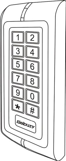
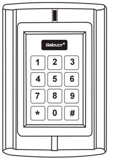
1 Waterproof Keypad/Reader/Controller User Manual W1-C W3-C User manual
2 1. Packing List Name Quantity Remarks Digital Keypad-W1-C/W3-C 1 User manual 1 Screw driver 1 Rubber bungs 4 6*27mm, used for fixing Self tapping screws 4 3.5*27mm, used for fixing Manager Card 2 Manager Add Card & Manager Delete Card Please ensure that all the above contents are correct. If any are missing please notify the supplier of the W1-C/W3-C. 2. W1-C/W3-C Quick Reference Programming Guide To enter the programming mode * Master code # is the default factory master code To exit from the programming mode * Note that to undertake the following programming the master user must be logged in To change the master code 0 New code # New code # The master code can be 6 digits long To add a PIN user 1 User ID number # PIN # The ID number is any number between 1 ~ The PIN is any 4~8 digits between 0000 ~ with the exception of 1234 which is reserved. Users can be added continuously without exiting programming mode To add a card user 1 Read Card # Cards can be added continuously without exiting from programming mode To delete a PIN or a card user. 2 User ID number # for a PIN user or 2 Read Card # for a card user 2
3 Users can be deleted continuously without exiting from programming mode To unlock the door To unlock the door for a PIN user Enter the PIN then press # To unlock the door for a card user Present the card 3. Description The W1-C/W3-C is single door multifunction standalone access controller or a Wiegand output keypad or card reader. It is suitable for mounting either indoor or outdoor in harsh environments. It is housed in a strong, sturdy and vandal proof Zinc Alloy electroplated case which is available in either a bright silver or matt silver finish. The electronics are fully potted so the W1-C/W3-C is waterproof and conforms to IP68. The W1-C/W3-C supports up to 2000 users in either a Card, 4~8 digits PIN, or a Card + PIN option. The inbuilt card reader supports EM 125KHZ frequency cards/tags. The W1-C/W3-C has many extra features including block enrollment, wiegand 26 bits interface, and backlit keypad etc. These features make W1-C/W3-C an ideal choice for door access not only for small shops and domestic households but also for commercial and industrial applications such as factories, warehouses, laboratories, banks and prisons. 4. Features Waterproof, conforms to IP68 Strong Zinc Alloy Electroplated anti-vandal case Full programming from the keypad 2,000 users, supports Card, PIN, Card + PIN Can be used as a stand alone keypad, Pin length 4~8 digits Backlight keypad Wiegand 26 input & output One programmable Relay output, NO, NC, COM Adjustable Door Output time, Alarm time, Door Open time Block enrollment, can enroll maximum 2000 consecutive card within 2 minutes Very low power consumption (<60mA) Easy to install and program Built in light dependent resistor (LDR) for anti tamper Built in buzzer Red, Yellow and Green LEDs display the working status 12~24V AC/DC 3
4 Two-year warranty 4
5 5. Specifications Operating Voltage 12~24V AC/DC User Capacity 2,000 Keypad 12 keys, 2 x 6 digits(w1-c) 12 keys, 3 x 4 digits(w3-c) Card Type EM 125 KHZ card Card Reading Distance 3~6 cm Active Current <80mA Idle Current 40mA Lock Output Load Max 2A Alarm Output Load Max 20A Operating Temperature -20~60 Operating Humidity 5%~95% RH Environment Conforms to IP68 Adjustable Door Relay time 0 ~ 99 seconds Adjustable Alarm Time 0 ~ 3 minutes Wiegand Interface Wiegand 26 input & output Wiring Connections Electric Lock, Exit Button, DOTL, External Alarm Dimensions L135 x W58 x H26 mm (W1-C) L128x W82 x H28 mm (W3-C) Net Weight 550 g Gross Weight 700 g 6. Installation Remove the back cover from the keypad using the supplied security screwdriver Drill 4 holes on the wall for the screws and I hole for the cable Fix the back cover firmly on the wall with 4 flat head screws Thread the cable through the cable hole Attach the keypad to the back cover. 5

6 7. Wiring Color Function Description Green D0 Wiegand Output D0 White D1 Wiegand Output D1 Grey Alarm - Alarm Negative Yellow OPEN Request to Exit Button Brown D-In Door Contact Red 12V~24V AC&DC 12~24V AC&DC Regulated Power Input Black 12V~24V AC&DC 12~24V AC&DC Regulated Power Input Blue NO Relay NO Purple COM Relay COM Orange NC Relay NC Pink GND W1-C/W3-C Negative Connection Diagram 6
7 Notes: Connect the negative pole of the lock to NC is for Fail safe lock. Connect the negative pole of the lock to NO is for Fail-secure lock. 7
8 8. To Reset to Factory Default To reset to factory default, power off, press *, hold it and power on, release it until hear two beeps and the LED shines in orange, then read any two EM cards, the LED will turn in red, means reset to factory default setting successfully. Of the two EM cards read, the first one is Manager Add card, the second one is Manager Delete card. Remarks: Reset to factory default, the user s information is still retained. 9. Anti Tamper Alarm The W1-C/W3-C uses a LDR (light dependent resistor) as an anti tamper alarm. If the keypad is removed from the cover then the tamper alarm will operate. 10. Sound and Light indication Operation Status Red Light Green Light Yellow Light Buzzer Power on Bright - - Short Ring Stand by Bright Press keypad Short Ring Operation successful - Bright - Short Ring Operation failed Short Rings Enter into programming mode Bright - - Short Ring In the programming mode - - Bright - Exit from the programming Bright - - Short Ring mode Open the door - Bright - Short Ring Alarm Bright - - Alarm 8
9 11. W1-C/W3-C Detailed Programming Guide 11.1 User Settings To enter the programming mode * Master code # To exit from the programming mode * is the default factory master code Note that to undertake the following programming the master user must be logged in To change the master code 0 New code # New code # The master code is any 6 digits Setting the working mode: Set valid card only users Set valid card and PIN users Set valid card or PIN users 3 0 # Entry is by card only 3 1 # Entry is by card and PIN together 3 2 # Entry is by either card or PIN (default) To add a user in either card or PIN mode ( 3 2 # ) (Default setting) To add a Pin user 1 User ID number # PIN # The ID number is any number between 1 ~ The PIN is any 4~8 digits between 0000 ~ with the exception of 1234 which is reserved. Users can be added continuously without exiting from programming mode as follows: 1 User ID no 1 # PIN # User ID no 2 # PIN # To delete a PIN user 2 User ID number # Users can be deleted continuously without exiting programming mode To change the PIN of a PIN user (This step must be done out of programming mode) To add a card user (Method 1) This is the fastest way to enter cards using ID number auto generation. To add a card user (Method 2) * ID number # Old PIN # New PIN # New PIN # 1 Read card # Cards can be added continuously without exiting programming mode 1 ID number # Card # This is the alternative way to enter cards using User ID Allocation. In this 9
10 method a User ID is allocated to a card. Only one user ID can be allocated to a single card. To add card user (Method 3) Add a series cards users Block Enrollment To delete a card user by card number. Note users can be deleted continuously without exiting programming mode To delete a card user by user ID. This option can be used when a user has lost their card 5 ID number # 8 digits Card number # Card quantity # Card quantity is between 1 ~ The 8 digits card number is the last 8 digits on the card. Maximum 2000 cards can be enrolled at a stretch within 2 minutes. 2 Read Card # 2 User ID # To add a card and PIN user in card and PIN mode ( 3 1 # ) To Add a card and Pin user (The PIN is any 4~8 digits between 0000 & with the exception of 1234 which is reserved.) To change a PIN in card and PIN mode (Method 1) Note that this is done outside programming mode so the user can undertake this themselves To change a PIN in card and PIN mode (Method 2) Note that this is done outside programming mode so the user can undertake this themselves To delete a Card and PIN user just delete the card Add the card as for a card user Press * to exit from the programming mode Then allocate the card a PIN as follows: * Read card 1234 # PIN # PIN # * Read Card Old PIN # New PIN # New PIN # * ID number # Old PIN # New PIN # New PIN # 2 User ID # To add a card user in card mode ( 3 0 # ) To Add and Delete a card user The operating is the same as adding and deleting a card user in 3 2 # To delete All users 10
11 To delete ALL users. Note that this is a dangerous option so use with care # To set card users by Manager card To add user by Manager Add Card Manager add card Read card Manager add card Cards can be added continuously. To delete User by Manager Delete Card Manager delete card Read Card Manager delete card Cards can be deleted continuously. To unlock the door For a PIN user Enter the PIN then press # For a card User Read card For a card and PIN user Read card then enter PIN # 11.2 Door Relay, Door Detecting, Alarm Settings Door relay time setting To set door relay strike time 4 0~99 # The door relay time is between 0~99 seconds, the factory default setting is 5 seconds. Door Open Detection Door Open Too Long (DOTL) warning. When used with an optional magnetic contact or built-in magnetic contact of the lock, if the door is opened normally, but not closed after 1 minute, the inside buzzer will beep automatically to remind people to close the door and continue for 1 minute before switching off automatically. Door Forced Open warning. When used with an optional magnetic contact or built-in magnetic contact of the lock, if the door is opened by force, or if the door is opened after 20 seconds of the electro-mechanical lock not closed properly, the inside buzzer and alarm output will both operate. The Alarm Output time is adjustable between 0~3 minutes with the default being 1 minute. To disable door open detection. (Factory default) 6 0 # To enable door open detection 6 1 # Alarm output time To set the alarm output time (0~3 minutes) Factory default is 1 minute 9 0~3 # 11
12 Keypad Lockout & Alarm Output options. If there are 10 invalid cards or 10 incorrect PIN numbers in a 10 minute period either the keypad will lockout for 10 minutes or the alarm will operate for 10 minutes, depending on the option selected below. Normal status: No keypad lockout or alarm (factory default) 7 0 # (Factory default setting) Keypad Lockout 7 1 # Alarm Output 7 2 # To remove the alarm To reset the Door Forced Open warning Read valid card or Master Code # To reset the Door Open Too Long warning Close the door or Read valid card or Master Code # 12. Interconnecting Two Devices 12.1 W1-C/W3-C operating as a Wiegand Output Reader In this mode the W1-C/W3-C supports a Wiegand 26 bit output so the Wiegand data lines can be connected to any controller which supports a Wiegand 26 bit input. See figure 1. Figure 1 Transmission Format: 1: Keypad Transmission The Reader will transmit the PIN data when it receives the last key (#) press after PIN code. 12
13 Format: PIN Code (any 4~8 digits between 0000 ~ ) Example: PIN code: Press #, then the output format will be: (Note: if press an invalid PIN (any 4~8 digits), the data will be also transmitted.) 2: Proximity Card Transmission The Reader will transmit the card data when it reads the Card. Format: Card Number (the last 8 digits of Card Number) (Note: no matter the card is valid or invalid, the data will be transmitted) 12.2 W1-C/W3-C operating as a Controller In this mode the W1-C/W3-C supports a Wiegand 26 bit input so an external Wiegand device with a 26 bit output can be connected to the Wiegand input terminals on the W1-C/W3-C. Either an ID card reader (125 KHZ) or an IC card reader (13.56MHZ) can be connected to the W1-C/W3-C. Cards are required to be added at the external reader, except where an external EM reader is used, in this case cards can be added at either reader or controller. See figure 2. Figure 2 13
W3-H Waterproof Keypad/Reader/Controller
 W3-H Waterproof Keypad/Reader/Controller User Manual 1. Packing list Name Quantity Digital Keypad W3-H 1 User Manual 1 Screw Driver Rubber Bungs Self Tapping Screws Diode 1 4 4 1 Manager Card 2 Remark
Standalone Keypad Access Control. User Manual. SS-TS2000 Size:120*80*25 mm
 Standalone Keypad Access Control User Manual SS-TS2000 Size:120*80*25 mm Please read the manual carefully before use this unit 1. Packing List Name Quantity Remarks Keypad 1 User manual 1 Screw driver
Standalone Keypad Access Control. User Manual. Please read the manual carefully before use this unit
 Standalone Keypad Access Control User Manual Please read the manual carefully before use this unit 1. Packing List Name Quantity Remarks Keypad 1 User manual 1 Screw driver 1 Φ20mm 60mm,Special for keypad
W3-M. Metal waterproof standalone access control/reader. User Manual
 W3M Metal waterproof standalone access control/reader User Manual Name Digital Keypad W3M User Manual Screw driver Rubber bungs Selftapping screws Diode 1. Packing List Quantity 1 1 1 4 4 1 Remark 6*27mm,
CV-110SPK Standalone Keypad/Prox Access Control Installation Instructions
 CV-110SPK Standalone Keypad/Prox Access Control Installation Instructions 1. Packing List Qty Name Remarks 1 1 1 2 2 1 Keypad User manual Screwdriver Wall plugs Self-tapping screws Torx screw 0.8 x 2.4
CM-110SK Standalone Keypad Installation Instructions
 CM-0SK Standalone Keypad Installation Instructions. Packing List Qty Name Remarks 2 2 Keypad User manual Screwdriver Wall plugs Self-tapping screws Torx screw 0.8 x 2.4 Φ(20 mm 60 mm) 0.24 x.2 Φ (6 mm
Single Door Standalone Access Control User Manual
 Single Door Standalone Access Control User Manual Reading this manual carefully before install and use the device 1. Packing List Name Quantity Remarks Keypad User manual Screw driver Rubber plug Self
BC Digital Keypad. User Manual
 BC2200 Digital Keypad User Manual Name Digital Keypad BC2200 User manual Screw driver Rubber bungs Self tapping screws Diode 1. Packing List Quantity Remarks 1 1 1 4 Φ6mm 28 mm, used for fixing 4 Φ4mm
DOLXFD1000B. Waterproof Access Control/Reader
 DOLXFD1000B Waterproof Access Control/Reader INTRODUCTION The DOLXFD1000B is a single- entry multi-function Access Controller with integrated keypad and card reader. It is designed and manufactured to
CV-550SPK V2 Waterproof Keypad/Reader/Controller Installation Instructions
 CV-550SPK V2 Waterproof Keypad/Reader/Controller Installation Instructions Packing List NAME MODEL/SIZE QTY Self tapping screw 0.15 x 1.06 (4mm 27 mm) Rubber plug 0.23 x 1.2 (6mm 30 mm) Star screw driver
TEC100 USER/INSTALLER MANUAL V2.0 REV. 03/2018
 TEC100 USER/INSTALLER MANUAL V2.0 REV. 03/2018 00. CONTT 01. SAFETY INSTRUCTIONS INDEX 01. SAFETY INSTRUCTIONS STANDARDS TO FOLLOW 02. PRODUCT PRODUCT PROFILE TECHNICAL PARAMETERS 03. INSTALLATION PRODUCT
User Manual. PCKeypad Wireless Keypad
 User Manual PCKeypad Wireless Keypad Description The PCKeypad is a wireless keypad with a PentaCODE transmitter built-in. It works with all of Elsema s PCR series receivers. The installer has the option
VIDI-AC-2CS Access Controller/ Reader
 VIDI-AC-2CS Access Controller/ Reader User Manual CONTENTS INTRODUCTION 2 INSTALLATION.4 STANDALONE MODE 6 CONTROLLER MODE.11 WIEGAND READER MODE.. 13 ADVANCE APPLICATION..14 1 INTRODUCTION The VIDI-AC-2CS
RD-SR2 ACCESS SECURITY PRODUCTS LTD. Proximity Card Reader with Remote Control. User Manual
 RD-SR2 Proximity Card Reader with Remote Control User Manual INTRODUCTION The RD-SR2 is a compact, weather resistant multi-function card reader that can be used as a standalone programmable access control
Fingerprint Access Control F1. User Manual
 Fingerprint Access Control F1 User Manual 1. Introduction F1 is a metal shell standalone fingerprint access control, using the America Atmel s MCU, with precise electron circuit and good productive technology.
F6-Fingerprint. Access Control/Reader. User Manual. F6 - Simplified Instruction. (Master Code) # (Factory default:1234) Enter the Programming Mode
 # (Factory default:1234) Enter the Programming Mode") -Fingerprint Access Control/Reader Function Description Enter the Programming Mode - Simplified Instruction Operation (Factory default:1234) Change the Master Code Add Fingerprint User Add Card User Add
-Fingerprint Access Control/Reader Function Description Enter the Programming Mode - Simplified Instruction Operation (Factory default:1234) Change the Master Code Add Fingerprint User Add Card User Add
Stand-alone Proximity Access Control
 Stand-alone Proximity Access Control User Manual INTRODUCTION VIDI-AC-1C is a compact, waterproof stand-alone programmable access control system that provides proximity entry for up to 2000 users. It uses
-DTZ001- Stand-Alone Proximity Access Control. User Manual
 -DTZ001- Stand-Alone Proximity Access Control User Manual INTRODUCTION DTZ001 is a compact, waterproof stand-alone programmable access control system that provides proximity entry for up to 2000 users,
RBR-SB-KTZ001 LAR 2. User Manual
 RBR-SB-KTZ001 LAR 2 User Manual INTRODUCTION KTZ001 is a compact, waterproof stand-alone programmable access control system that provides proximity entry for up to 2000 users. Read both EM and HID card.
User Manual. Split access control with intelligent secured power supply.
 User Manual Split access control with intelligent secured power supply. Contents. Introduction, features and specifications. Installation and Wiring Diagram 3. Manager Card Operation 4. User Settings 5.
Digital Keypad Introduction
 K2 Digital Keypad Introduction The K02 uses the latest microprocessor technology to operate door strikes and security systems that require a momentary (timed) or latching dry contact closure. All programming
VIS-3200 / VIS-3201 User Manual
 2.4GHz Indoor Black Wireless Exit Button Receiver Keypad / Reader Access Control 500 Users Range of 50 Feet Delay and On/Off Toggle Mode Battery Operated Standalone No Software 1 VIS-3200 / VIS-3201 User
CC Series metal access control Manual
 CC Series metal access control Manual 1.Description CC Series is a standalone for two doors, support card, pin, card+pin access way. It is with 2 relays to control 2 doors and supports up to 2000 users
EL-ST100 KEYPAD CONTROLLER
 WIRING DIAGRAM EL-ST100 KEYPAD CONTROLLER WEATHER-PROOF STANDALONE ACCESS CONTROLLER WITH KEYPAD & PROXIMITY TECHNOLOGY Programming and Installation Manual NOTE: www.elock2u.com ICT at work! Version 3.6
Installation and User Manual
 S2 Metal Waterproof Access Control Unit Installation and User Manual (Ness Part No. 101-082) 1 Introduction Ness S2 is an advanced, waterproof (IP65 rated) proximity and PIN Access Controller. S2 can support
DG-800 Stand-Alone Proximity Reader Instruction Manual
 DG-800 Stand-Alone Proximity Reader Instruction Manual I. Features 1. Memory volume up to 1000+10 proximity cards/tokens and PINs with the programming time up to 0.5 seconds. 2. Access modes: a. Only Proximity
Instruction Manual. Vogue. Security. Technology. Innovation 2013-V01
 Instruction Manual DH16A-60DTE Model 60 with plastic keypad, stand alone access control DH16A-60DTQE Model 60 with plastic keypad, networked access control 2013-V01 Security Technology Vogue Innovation
Metal Standalone Keypad Access Control S100
 Metal Standalone Keypad Access Control S100 Waterproof, conforms to IP68 Can connect external reader Strong Zinc Alloy Electroplated anti-vandal case Full programming from the keypad 2000 uses, supports
ACCESS CONTROL SYSTEM
 ACCESS CONTROL SYSTEM System versions Standalone controllers series based on integrated models KZ-400, 500, 600, 700, KZC-300,800, 900 KaDe Lite system based on integrated controllers KZ-1000 KaDe Premium
Partizan PAB-FC2. Fingerprint scan time Fingerprint identification time. <0.5 s < % <0.0198% Ingress protection rating
 1. Features & Technical Parameters 1.1 Features: Partizan PAB-FC2 Metal vandalproof housing Secure and reliable biometric fingerprint recognition Simple for using, wiring can be done by a user without
HSY-S209 EM Metal waterproof access control system User Manual
 HSY-S209 EM Metal waterproof access control system User Manual Reading carefully before Install and use this manual 1. Product Profile The product is Contact-less inductive card Metal Password Access Controller,
BHD-8000 Access Control Keypad and Card Reader. Wiring Diagram
 BHD-8000 Access Control Keypad and Card Reader Wiring Diagram Frontal View Main Technical Specifications Item Operating Voltage Unlock Relay Operating Temperature Value 12VDC+12%/1.2A 12VDC/2A Normal Operation:
1. Product Specification
 1. Product Specification Item Specification Voltage 12VDC +10%, Current 1.2A Lock Relay 12VDC/2A Environmental Temperature working:0 ~45 ; storage:-10 ~55 Relative humidity working:40%~90%rh; Card Capacity
EZTAG3 PROXIMITY AND KEYPAD DOOR ENTRY
 EZTAG PROXIMITY AND KEYPAD DOOR ENTRY USER MANUAL www.espuk.com EZTAG Manual_Layout.indd 8//06 5:8:0 System Components Proximity and Reader 0 x Proximity Tags x Hex Key x Plastic wall plug x Countersunk
CV-945 Stand-Alone Biometric Reader. Installation Instructions
 CV-945 Stand-Alone Biometric Reader Installation Instructions Contents 1.0 Introduction... 03 2.0 Mounting... 03 3.0 Specifications... 04 4.0 Application Diagram... 04 5.0 Wiring... 05 6.0 Recommended
REX F-0-9 Standalone or Access Controller
 REX F-0-9 Standalone or Access Controller Power supply The controller need s external power supply to operate. The Spider W40 power supply is sufficient to power two controllers and two 12V electric strikes
SL2000E. Status Output. Electronic Code Lock. Features. Input. Exit Button Input. Introduction. Door Contact Input. Functional Description.
 SL2000E Electronic Code Lock Features Door Relay output Status transistor output Aux transistor output Door Contact input Exit Button input INSTALLER code for programming MASTER code for arming/disarming
EZTAG3 PROXIMITY AND KEYPAD DOOR ENTRY
 EZTAG Manual.qxp_Layout 0/0/06 :7 Page EZTAG PROXIMITY AND KEYPAD DOOR ENTRY USER MANUAL www.espuk.com EZTAG Manual.qxp_Layout 0/0/06 :7 Page System Components Proximity and Reader 0 x Proximity Tags x
Specifications: Features:
 ROFU Features: Applicable card mode EM Card / Key Fob 1 Administrator and 200 Users 200 Proximity Cards / Key fobs Access Modes:Use Bluetooth smartphone or Card / Key fob to access Built-in Tamper alarm
INSTALLATION INSTRUCTIONS 920P EntryCheck TM
 801 Avenida Acaso, Camarillo, Ca. 93012 (805) 494-0622 www.sdcsecurity.com E-mail: service@sdcsecurity.com INSTALLATION INSTRUCTIONS 920P EntryCheck TM The EntryCheck 920P Indoor/Outdoor Keypad is a surface-mount
_ Access control SISTEMAS DE SEGURIDAD
 _ Access control SISTEMAS DE SEGURIDAD SECURITY SYSTEMS Access control 01 Concept 02 Product 03 Characteristics 04 Compatibility 05 New functions 06 New software 07 References, accessories and diagrams
VANDAL RESISTANT BACK-LIT WEATHERPROOF ACCESS CONTROL KEYPAD
 VANDAL RESISTANT BACK-LIT WEATHERPROOF ACCESS CONTROL KEYPAD Post Mount Keypad Programming & Installation Manual 1. Connect Power 12V DC to 24V AC/DC to terminals (+) and (-) Post Mount Keypad Quick Start
FTK5 PROXIMITY KEYPAD
 FTK5 PROXIMITY KEYPAD Before using the unit, please read the instructions and retain for future reference 1 There are 600 user codes (fobs or cards) and 1 programming code: Careful administration records
EZ-TAG2 Manual_Layout 5 11/12/ :14 Page 1 U S E R M A N UAL
 EZ-TAG2 Manual_Layout 5 11/12/2012 09:14 Page 1 USER MANUAL EZ-TAG2 Manual_Layout 5 11/12/2012 09:14 Page 2 Contents EZ-TAG2 and Back Plate 1 x Security Torx Key 4 x Screws and raw plugs 1 x Marking out
INSTALLATION INSTRUCTIONS 920 EntryCheck TM
 801 Avenida Acaso, Camarillo, Ca. 93012 (805) 494-0622 www.sdcsecurity.com E-mail: service@sdcsecurity.com INSTALLATION INSTRUCTIONS 920 EntryCheck TM The EntryCheck 920 Indoor/Outdoor Keypad is a surface-mount
Finger Vein Access Control device Quick Start Guide Version: 1.0 Date: June USB slot. USB slot
 Overview Fingerprint & Finger Vein Device Front Left Side: Finger Vein Device Touch screen Card reader Fingerprint reader Finger vein reader Finger vein sensor: During registration, after finger touches
AC-Q4x Family. Instruction Manual. Vandal Resistant Stand-Alone controllers. Models: AC-Q41H/HB AC-Q41SB AC-Q42H/HB AC-Q42SB AC-Q44
 AC-Q4x Family Vandal Resistant Stand-Alone controllers Instruction Manual ls: AC-Q41H/HB AC-Q41SB AC-Q42H/HB AC-Q42SB AC-Q44 December 2006 Table of Contents Table of Contents 1. General Information...
Installing Keypad and Backplate
 Installing Keypad and Backplate Fig.1 Positioning of Fixing Holes and Cable Outlet Cable Outlet, Drill Diameter 10mm for Cable Access Remove the back plate, which is fitted to rear of the keypad, using
DG Series. Access Control Proximity Readers DG-160 DG-800
 DG Series Access Control Proximity Readers DG-800 + DG-160 + Features: Applicable card modeem Card / Key Fob 1 Administrator and 200 Users 200 Proximity Cards / Key fobs Access ModesUse Bluetooth smartphone,
CP150B Vandal & Weather Resistant Keypad Security Systems
 Vandal & Weather Resistant Keypad Security Systems EN Security System CP150B - Vandal & Weather Resistant Keypad The CP150B keypad provides alarm and or access control functionality when used on selected
GV-Card Reader. User s Manual
 GV-Card Reader User s Manual Before attempting to connect or operate this product, please read these instructions carefully and save this manual for future use. READER-B 2016 GeoVision, Inc. All rights
INSTALLATION INSTRUCTIONS Model 930 EntryCheck
 SECURITY DOOR CONTROLS 3580 Willow Lane, Westlake Village, CA 91361-4921 (805) 494-0622 Fax: (805) 494-8861 www.sdcsecurity.com E-mail: service@sdcsecurity.com INSTALLATION INSTRUCTIONS Model 930 EntryCheck
genesis TECHNICAL MANUAL Two-Door Controller GEN-045
 Two-Door Controller GEN-045 Genesis Electronics Australia Pty Ltd www.genesiselectronics.com.au info@genesiselectronics.com.au Australian Owned, Designed and Manufactured Distributed By:- Genesis reserves
EX8. User Manual. Ver 1.0
 EX8 User Manual Ver 1.0 EX8 manual ver1.0 Power supply important issue! Use separate power supply when ever is possible, one for EX8 and Reader and another for door lock. This way electrical isolation
AC-115 Compact Networked Single-Door Controller Hardware Installation and Programming
 AC-115 Compact Networked Single- Controller Hardware Installation and Programming Copyright 2013 by Rosslare. All rights reserved. This manual and the information contained herein are proprietary to REL,
Compact Keypad. ins /02/2010. Exit button (push to make) 12V DC release current rating must be less than 1A.
 12V DC release current rating must be less than 1A.") Compact Keypad Grey Exit button (push to make) 1V DC White Black 115V DC (fuse rating 1A) 1V DC release current rating must be less than 1A. The diode current rating must be equal to or greater than the
Compact Keypad Grey Exit button (push to make) 1V DC White Black 115V DC (fuse rating 1A) 1V DC release current rating must be less than 1A. The diode current rating must be equal to or greater than the
7612 Programming Instructions
 7612 Programming Instructions Built-in Proximity reader Read Range 65mm odulation ASK at 125kHz Compatible Cards ALL 26-Bit EM Cards 7612 is a vandal resistant proximity card and keypad access control
IBA-7612 Programming Instructions
 IBA-7612 Programming Instructions Built-in Proximity reader Read Range 65mm odulation ASK at 125kHz Compatible Cards ALL 26-Bit EM Cards IBA-7612 is a vandal resistant proximity card and keypad access
Wiring Diagram and Programming Instructions for MAW6 Digital Keypad and Proximity Card/F reader
 Wiring Diagram and Programming Instructions for MAW6 Digital Keypad and Proximity Card/F reader www.grantsautomation.com.au grant@grantsautomation.com.au Wiring Diagrams for MAW6 Digital Keypad For Pedestrian
GUARD CENTURION OPERATING INSTRUCTIONS THE AUTOMATIC CHOICE
 GUARD CENTURION THE AUTOMATIC CHOICE OPERATING INSTRUCTIONS 0 In a In hurry? a hurry? The following KwikLearn procedure and connection diagram will enable you to start using your SmartGUARD system right
INSTALLATION INSTRUCTIONS 921P EntryCheck TM
 80 Avenida Acaso, Camarillo, Ca. 90 (805) 494-06 www.sdcsecurity.com E-mail: service@sdcsecurity.com INSTALLATION INSTRUCTIONS 9P EntryCheck TM The EntryCheck 9P Indoor/Outdoor Keypad is a surface mount
CM-500 SK 500 USER CODES KEYPAD
 CM-500 SK 500 USER CODES KEYPAD Wiring diagram PCB front view ST2 1 3 1 3 N/C contact RL1 (magnet) N/O contact RL1 (strike) ST1 3 2 1 ST2 1 3 RL2 RL1 Strike 2 1 E M B 3 5 T C O 12 V V1 PB2 PB1 Input voltage
MODEL KP-100 ACCESS CONTROL DIGITAL KEYPAD OPERATING INSTRUCTIONS
 MODEL KP-100 ACCESS CONTROL DIGITAL KEYPAD OPERATING INSTRUCTIONS Model KP-100 is a self-contained digital keypad. This keypad is suitable for residential, industrial, and commercial installations. It
QUICK START GUIDE. 2.4 Inch TFT Terminal Time Attendance & Access Control
 QUICK START GUIDE 2.4 Inch TFT Terminal Time Attendance & Access Control Safety Precautions The following precautions are to keep user safe and prevent any damage. Please read carefully before installation.
Revision Date: 02 Mar 2018
 KAS Bluetooth Locks HOMES AIRBNB OFFICES SHARED SPACE Revision Date: 02 Mar 2018 COPYRIGHT: Information in this document is subject to change without further notice. No part of this document can be reproduced
2000 Series e/em Style Keypad Installation and Programming Manual
 2000 Series e/em Style Keypad Installation and Programming Manual Document Number: 6054022 Revision: 0 Date: 12/21/06 Table of Contents Table of Contents Section 1: Introduction... 6 1 Product Description...6
KP2000E/EM Series Style Keypad
 23852973 KP2000E/EM Series Style Keypad Installation and Programming Instructions Models KP2000EXX and KP2000EMXX Specifications Parameter Voltage Requirements Keypad Current Requirements (Max) Relay Contact
GV-AS Controller. Installation Guide
 GV-AS Controller Installation Guide Before attempting to connect or operate this product, please read these instructions carefully and save this manual for future use. 2011 GeoVision, Inc. All rights reserved.
RFID PRODUCT AND SYSTEM
 EL500(T)-X-XX Access control system, EM125kHz technology EL500-X-0C EL500-X-1C EL500-X-0D Economic access control system, EM125kHz technology Economic access control system, EM125kHz technology, with keypad
212iL Rev. 1.1
 212iL 1 International Electronics, Inc. 427 Turnpike Street Canton, Massachusetts 02021 212iL (illuminated Luxury) Keypad Single Unit Keypad- Control Installation Manual Features: 120 User Capability Illuminated
ACTsmart2 Product Range Operating and Installation Instructions
 ACTsmart2 Product Range Operating and Installation Instructions 18-00045 Contents ORDERING INFORMATION......4 INSTALLATION NOTES......5 IMPORTANT......5 PRODUCT SPECIFICATION......5 30 SECOND PROGRAMMING
Two Door Controller GEN-045
 Australian Owned, Designed and Manufactured Two Door Controller GEN-045 Genesis Electronics Australia Pty Ltd www.genesiselectronics.com.au Distributed by: Genesis reserves the right to change or modify
Waterproof Exit Button x40x30/44mm - IP68, 304 Stainless Steel - Voltage: DC12V, DC9-24V (-W402N)
") Touch & No Touch Exit Buttons s Infra-Red No Touch Exit Buttons ADB-11-CO (No Touch)/ ADB-13-CO (Hand icon) - 86x86x39mm - Sensing distance: 0.1-15cm - Installation: use with 86*86 back box ADB-12-CO (No
Touch & No Touch Exit Buttons s Infra-Red No Touch Exit Buttons ADB-11-CO (No Touch)/ ADB-13-CO (Hand icon) - 86x86x39mm - Sensing distance: 0.1-15cm - Installation: use with 86*86 back box ADB-12-CO (No
Installation Guide for PR311SE and PR311SE-BK v1.0 Access Controllers Rev. B
 Installation Guide for PR311SE and PR311SE-BK v1.0 Access Controllers Rev. B Introduction This document contains minimum information that is necessary to properly install the device and to perform its
EcoEntry. RFID Proximity Access Control System. User Guide. Revision 2
 EcoEntry RFID Proximity Access Control System User Guide Revision 2 Introduction The ecoentry door access system allows the user to open the door using a keyfob, password, or keyfob plus password. Specification
GV-EL124S Electric Strike
 GV-EL124S Electric Strike Featured with a built-in door status sensor, the GV-EL124S is a fail-secure electric strike, but it is field convertible from fail secure to fail safe. It can be mounted either
AYC-F/G/M60 Family Backlit goprox & PIN Reader Convertible Series with Genuine HID Technology Installation and Programming Manual
 AYC-F/G/M60 Family Backlit goprox & PIN Reader Convertible Series with Genuine HID Technology Installation and Programming Manual AYC-F60 AYC-G60 AYC-M60 Copyright 2013 by Rosslare. All rights reserved.
Wireless Key fob, Key pad & Receiver Range
 Wireless Key fob, Key pad & Receiver Range 4Ch Wireless Receiver 4x Voltage Free relay outputs (NO + NC) 100m Transmission range Multiple user codes 2 Channel wireless control Clear hinge up lid 12V DC
EN FULL DETAILS SKB. Vandal Resistant keypad - Full Details
 EN FULL DETAILS SKB Vandal Resistant keypad - Full Details WARNINGS Carry out the installation by carefully following the instructions provided by the manufacturer in accordance with the current standards.
Fast operation of IP Villa System V 1.0
 Fast operation of IP Villa System V 1.0 Contents 1 System Structure... 3 2 Operation Steps... 3 2.1 VTO WEB Config... 3 2.2 Main VTH Setup... 4 3 Group call Settings... 5 3.1 VTO web config... 5 3.2 Sub-
Keypad CT2000. Art. No.: , (black) Art. No.: , (white) Installation Manual
 Art. No.: , (white) Installation Manual") secure open Keypad CT Art. No.:, (black) Art. No.:, (white) Installation Manual CT_installation_ENGmay Conlan ApS Speditorvej A DK- Aalborg Tel: + Fax: + www.conlan.eu info@conlan.eu Table of contents.
secure open Keypad CT Art. No.:, (black) Art. No.:, (white) Installation Manual CT_installation_ENGmay Conlan ApS Speditorvej A DK- Aalborg Tel: + Fax: + www.conlan.eu info@conlan.eu Table of contents.
AYC-E/Q/T60 Family Backlit goprox & PIN Reader Convertible Series with Genuine HID Technology Installation and Programming Manual
 AYC-E/Q/T60 Family Backlit goprox & PIN Reader Convertible Series with Genuine HID Technology Installation and Programming Manual AYC-E60 AYC-Q60 AYC-T60 Copyright 2013 by Rosslare. All rights reserved.
PAC1 Door Access Controller
 PAC1 Door Access Controller Series 1 TABLE OF CONTENTS i PAGE Introduction...1 Features...1 Specifications...2 Terminal Descriptions...3 Programmable Features Description...5 Automatic Relock Function...5
Indoor/Outdoor Proximity Reader and Keypad with 10cm (4in) Read Range
 Read Range") Indoor/Outdoor Proximity Reader and Keypad with 10cm (4in) Read Range Stand alone CR-R885-SB Installation and Operating Instructions V1.1 TABLE OF CONTENTS Installation... 2 Mounting and Wiring... 2 Mounting
Indoor/Outdoor Proximity Reader and Keypad with 10cm (4in) Read Range Stand alone CR-R885-SB Installation and Operating Instructions V1.1 TABLE OF CONTENTS Installation... 2 Mounting and Wiring... 2 Mounting
PAC1 Door Access Controller
 PAC1 Door Access Controller Series 1 100% Designed and Manufactured by: NIDAC SECURITY PTY. LTD. 2 CROMWELL STREET BURWOOD, VICTORIA Tel: (03) 9808 6244 AUSTRALIA 3125 Fax: (03) 9808 9335 Revision 1.1
AC-Q4x Family Anti-Vandal Standalone Controllers Installation and Programming Manual
 AC-Q4x Family Anti-Vandal Standalone Controllers Installation and Programming Manual ls: AC-Q41H/HB AC-Q41HP AC-Q41SB AC-Q42H/HB AC-Q42HP AC-Q42SB AC-Q44 Copyright 2014 by Rosslare. All rights reserved.
SF200. Installation Guide & Quick Start Guide. 2 TFT AC Terminal Version: 1.0 Date: June 2014
 SF200 Installation Guide & Quick Start Guide 2 TFT AC Terminal Version: 1.0 Date: June 2014 All design and specification declared are subject to change without notice in advance. Contents Safety Precautions
Access control panel U-Prox IC E (Elevator control)
") 1.003 Access control panel U-Prox IC E (Elevator control) Installation and programming manual About this document http://u-prox.com This manual covers installation, adjustment and use of U-Prox IC E (hereinafter
1.003 Access control panel U-Prox IC E (Elevator control) Installation and programming manual About this document http://u-prox.com This manual covers installation, adjustment and use of U-Prox IC E (hereinafter
AS Keypad User Manual
 AS Keypad User Manual Specifications Operating Voltage: 12~24 VAC/DC Current Draw: TBA Input: request-to-exit (for Relay 1) time out reed switch contact (for Relay 1) Output: Relay 1: N.O./N.C./Com. Output
INSTRUCTION MANUAL AC-T43 PIEZO-KEYPAD STANDALONE ACCESS CONTROL UNIT. 07/04
 INSTRUCTION MANUAL 1 2 3 4 5 6 7 8 9 0 # PIEZO-KEYPAD STANDALONE ACCESS CONTROL UNIT www.rosslaresecurity.com 0706-0960050-00 07/04 Contents INTRODUCTION 4 Technical Specifications 5 Key Features 6 INSTALLATION
Section 1 General Description. Section 3 How to Program Keypad. Section 2 Installation. CM-120TX Wireless Digital Keypads Installation Instructions
 CM-120TX Wireless Digital Keypads Installation Instructions Package Contents - (1) Keypad and faceplate assembly - (1) Foam gasket (CM-120W only) - (2) #6-32 x 1 S/S Phillips screws - (2) #6-32 x 1 Tamperproof
Wiring Guide EP.NMINI. Version 1.02 Last Updated:
 Wiring Guide EP.NMINI Version 1.02 Last Updated: 14-10-2014 1 Note: See http://www.entrypass.net/ for updates, revisions, and download the latest installation manual There are currently 2 version of EntryPass
ECI1. COMPASS display. ECI1-REV For latest update: Electronic Compass Indicator ECS1
 ECI1 COMPASS display Electronic Compass Indicator ECS1 ECI1-REV. 1.3 20-12-2004 For latest update: www.elproma.com/compass Contents 1 Introduction... 1 1.1 Package contents... 1 2 Working... 2 2.1 The
TOUCHLOCK compact. Master code: Paxton Access Ltd. ins TOUCHLOCK compact kit. Document Contents. Instructions for the following:
 ins-016 160499 TOUCHLOCK compact 100-050 TOUCHLOCK compact kit Instructions for the following: 526-886 TOUCHLOCK compact keypad 100-050 TOUCHLOCK compact kit Master code: Document Contents About this product...2
AYC-Ex5/T65 Family Convertible Backlit Proximity & PIN Readers/Controllers Installation and Programming Manual
 AYC-Ex5/T65 Family Convertible Backlit Proximity & PIN Readers/Controllers Installation and Programming Manual Ex5 Models: AYC-E55 AYC-E65BB AYC-E65BG AYC-E65BW T65 Models: AYC-T65B AYC-T65N AYC-Ex5 AYC-T65
GV-RK1352 and GV-R1352 Card Reader
 GV-RK1352 and GV-R1352 Card Reader The GV-RK1352 and GV-R1352 are card readers designed to recognize identifications cards. GV-RK1352 comes with keypad, allowing it to also recognize PIN codes. Featured
Operating Instructions KEYPAD. Compatible WIRELESS ACCESS CONTROL
 Operating Instructions KEYPAD Compatible WIRELESS ACCESS CONTROL Contents Technical specifications page 1 Approvals page 1 Changing the Master code page 2 Adding a User code page 3 Deleting a User code
Wireless Digital Video Doorbell
 Wireless Digital Video Doorbell User s Manual Door Camera Indoor Handset Remark Please follow the user manual for correct installation and testing, if there is any doubt, please call our tech-supporting
RFID/Digital Access Control Keypad
 R Luminous/ RFID/Digital Access Control Keypad Model:YK-368L-R Germany EMC tested FEATURES AND FUNCTIONS Simple Programming, Easy Operation 3-Operation Mode: ID Card Operation, User Code Operation, ID
E-Access ANXELL TECHNOLOGY CORPORATION E3AK4 E3AK2. Specifications Voltage (Input): 12 to 24 VDC
: 12 to 24 VDC") E-Access E3AK1 E3AK2 E3AK3 E3AK4 4-3/4" x 2-15/16" x 1-13/16" (120 x 74 x 46.2 mm ) 4-1/2" x2-3/4" x1-5/8" (114 x 70 x 41 mm) 4-13/16" x 3" x 2-1/2" (123 x 77 x 64.2 mm) 3-7/16" x 3-7/16" x 1-3/4" (87.3
E-Access E3AK1 E3AK2 E3AK3 E3AK4 4-3/4" x 2-15/16" x 1-13/16" (120 x 74 x 46.2 mm ) 4-1/2" x2-3/4" x1-5/8" (114 x 70 x 41 mm) 4-13/16" x 3" x 2-1/2" (123 x 77 x 64.2 mm) 3-7/16" x 3-7/16" x 1-3/4" (87.3