LPG STM 94442A User s Manual
|
|
|
- Kory Townsend
- 5 years ago
- Views:
Transcription

1 1 LPG STM 94442A User s Manual This Manual belongs to: Company:
2 3 Table of Contents Features Hardware Installation...5 Monitor Mounting Dimensions Monitor Specifications...8 Sender Specifications Product Overview ) LCD Display..10 Programming Low and High Set Points ) Alarm Relay ) Analog Outputs..13 4) 4-20mA Analog Output Details.15 5) Connection Details.18 a) Connection Detail for Rochester Hall Effect Sender..18 b) Connection Detail for an External 4-20mA Signal Remote sender ) -48 VDC Power Source Connection Details..23 PC Connections Using RS232 Serial Interface..24 a) RS232 Serial Port 1 Connection and Operation (DEV port).24 b) RS232 Serial Port 2 Connection and Operation (COM port) 26 Most Frequently Asked Questions and Answers (Q & A)...28 Warranty..29
3 Features LPG Stationary Tank Monitor PN#94442A LPG 4 The 94442A Stationary Tank Monitor (STM) is used for measuring LPG level in a tank. It can be installed indoors or outdoors at a convenient location that can be up to 300 feet from the tank. A level sender is also included which must be installed in the float gage located on the tank. The LPG tank does not have to be emptied or purged to install the sender. It s universal design fits most junior and senior LPG float gages and includes a direct read pointer that can be used to indicate LPG level at the tank Monitors 2 LPG Tank Levels (Sensor for second tank optional) State-of-the-art intelligent microprocessor based electronics Large LCD readout indicating Level, Low Set Point and High Set Point for each channel Hi/Lo alarm set points programmable using built-in pushbuttons One Form C (NC-C-NO) contact available for each channel. Contact rating 3 Amps Analog Output for each channel, 0 to 5 VDC standard, 4-20 ma optional RS232 Serial Interface for direct connection to PC/RTU or PLC NEMA 4 enclosure suitable for outdoor use Operates on 12 to 24 VDC power and a 120 VAC wall transformer is included for AC operation. One LPG sensor included to fit standard 2 junior float gage
4 Hardware Installation LPG Stationary Tank Monitor PN#94442A LPG 5 1) DO NOT INSTALL THE SENDER AT THE TANK YET. 2) Locate the place where the monitor is to be installed. Drill four holes according to the dimensions shown in Figure 2. Remove the lid of the monitor (undo 4 corner screws). Mount the monitor using the appropriate screws to fit through the feed-through holes on the four corners. 3) Temporarily connect the sender wires directly to the monitor as shown in Figure 8A. 4) Connect Relay contacts and Analog outputs as desired. Refer to Figure 5 and 6 respectively for connection details. 5) Connect power to the monitor either using the supplied 120 VAC transformer or a VDC power source supplied by the user. 6) APPLY POWER TO THE MONITOR. 7) The sender level can be changed manually by holding a small magnet at the bottom of the sender and rotating it clockwise or counter-clockwise such that the pointer in the sender follows the magnet. Observe the appropriate Level reading on the LCD display (L1 or L2) It should follow the LPG level indicated by the pointer. 8) Set the Low and High set points using the 5 pushbuttons as described in set point programming section above. When the level on the sensor is below the low set point or above the high set point the corresponding alarm relay will activate and the offending set point will blink on the display. 9) Disconnect power to the unit and the LPG sender. Install sender on the LPG tank. 10) Install and connect the cable between the sender and the monitor. Any 4 conductor, shielded, 16 to 22 awg., multi-strand, multi conductor cable can be used for this purpose. NOTE: if this cable is not installed in a conduit, then be sure to select a good outside grade cable that can be used for direct burial if necessary. 11) Apply power to the unit and make sure that the monitor is displaying the correct LPG level observed at the tank.
5 Overview LPG Stationary Tank Monitor PN#94442A LPG 6 A finished installation will look similar to this: Figure 1
6 7 Monitor mounting dimensions Figure 2

7 Monitor Specifications LPG Stationary Tank Monitor PN#94442A LPG 8 Power A.C. Transformer: Input 120VAC Output 12 Volts DC Output Current 0.2 Amps Monitor Input Power: Monitor Current Consumption: Sender Output: Maximum output voltage to sender: Maximum output current to sender: Volts DC 0.25 Amps max. 5 Volts DC 10 ma Alarm Relay specifications: 2 Form C contacts rated at 5 Amps each Analog output: Volts Output current: 0-5 Volts DC 20 ma max. Enclosure: NEMA 4x, sealed, weather-proof, designed for indoor or outdoor use. Monitor operating temperature: Monitor electrical rating: 10 to 150 F Class 1, Div. 2, groups C & D

8 9 Sender Specifications Operating Voltage range Operating temperature: Enclosure: 0-5 Volts DC max. -40 to 70 C -40 to 158 F Sealed Lexan top and bottom Ultrasonically welded Electrical specification: When used with STM PN# s: 94442A, 94442A: Class 1, Div. 2, groups C & D When used with unleaded gasoline use Intrinsically Safe Barriers # STAHL 9001/02-093/150/00 or equivalent: Class 1, Div. 1, groups C & D.
9 Product Overview The monitor contains the following: LPG Stationary Tank Monitor PN#94442A LPG 10 1) LCD Display Figure 3 indicates LPG level and corresponding Low and High Set points for 2 individual tanks. Top Line indicates parameters for Tank 1 and second line for Tank 2. Button 1 (blue) Tank 1 low set point Button 2 (blue) Tank 1 high set point Button 3 (blue) Tank 2 low set point Button 4 (blue) Tank 2 high set point Button 5 (red) Reverse adjustment Figure 3
10 Programming Low and High Set Points 11 There are 5 pushbuttons on the main board that are used to program the set points. Four pushbuttons are blue and are marked SW1, SW2, SW3 and SW4 form left to right. The fifth pushbutton is red and is marked SW5 and is used to change the direction of the Set Point count when being programmed by the other pushbuttons as described below. Only one set point must be modified at a time i.e. pressing SW1-SW4 at the same time may result in error. Refer to figure 4 below for details. a) Programming Tank 1 Low Set Point This set point is programmed by pressing the blue push button marked SW1. The low Set point for L1 will either increase or decrease. Set it to the desired value and the unit will automatically save it. The increase/decrease direction can be changed by pressing SW5 momentarily. b) Programming Tank 1 High Set Point This set point is programmed by pressing the blue push button marked SW2. The High Set point for L1 will either increase or decrease. Set it to the desired value and the unit will automatically save it. The increase/decrease direction can be changed by pressing SW5 momentarily. c) Programming Tank 2 Low Set Point This set point is programmed by pressing the blue push button marked SW3. The low Set point for L1 will either increase or decrease. Set it to the desired value and the unit will automatically save it. The increase/decrease direction can be changed by pressing SW5 momentarily. d) Programming Tank 2 High Set Point This set point is programmed by pressing the blue push button marked SW4. The High Set point for L1 will either increase or decrease. Set it to the desired value and the unit will automatically save it. The increase/decrease direction can be changed by pressing SW5 momentarily. e) Programming Sensor type Set the STM to use a Rochester 3-wire sensor by holding down the red button (SW5) and pressing SW1 to change value on the top line for channel 1 and SW2 to change value on the second line for CH2. (A value of 0 sets the unit to operate with the MDi wire sensor, this kind of sensor is no longer used). A value of 1 sets the unit to operate with the Rochester Hall Effect 3-wire sensor. LCD Display SW1 SW2 SW3 SW4 SW5 Figure 4


11 12 2) Alarm Relay An alarm relay is available for each channel that provides a Form C (NC-C-NO) contact rated at 120 VAC at 3 Amps. The alarm is activated whenever the actual tank level is either lower than the LO set point or higher than the HI set point. The relay is de-activated when the level is restored within the normal operation range. Figure 5 below show connection details for the contacts. Figure 5
.")
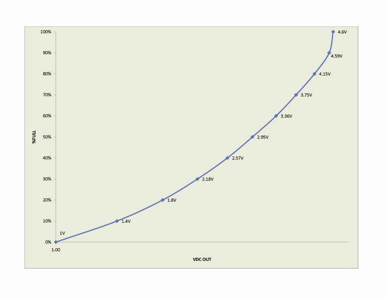
12 13 3) Analog Outputs A 0-5 Volt analog output is also provided for each channel. This output is typically used to connect to a remote monitoring device, programmable controller, etc. in order to access LPG tank levels. For Channel 1 connect to TB1-Top Level-2 and TB1-Bottom Level-2 and for Channel 2 connect to TB1-Top Level-3 and TB1-Bottom Level-3 (refer to figure 6A below). Figure 6B shows a graph of the analog output vs. the LPG level. This output can be connected to a signal conditioner to provide a 4-20 ma signal indicative of the LPG level. Figure 6A
13 VDC LPG Stationary Tank Monitor PN#94442A LPG 14 Analog Output for Rochester Hall Effect Sender % Level Analog Output VDC 0% % % % % % % % % % % % % % % % % % % % % % 10% 20% Rochester Sender 30% 40% 50% 60% % Level 70% 80% 90% 99% Figure 6B
14 15 4) 4-20 ma Analog Output Details Figure 7A

15 16 STM94442A Details showing 4-20mA Analog Output board installed for Channel 1 Figure 7B

16 17 Figure 7C

17 5) Connection Details LPG Stationary Tank Monitor PN#94442A LPG 18 a) Connection Detail for Rochester Hall Effect Sender The Rochester Remote gage has 2 parts i.e. the plastic Direct Read dial Face and the Sensor Element that snaps into the Dial. Refer to diagram below for connection details. Wire Color Channel 1 Channel 2 Red TB1 Top Level 7 TB1 Bottom Level 7 White TB1 Top Level 6 TB1 Bottom Level 6 Black TB1 Top Level 5 TB1 - Bottom Level 5 Figure 8A

18 19 Jumper Settings for Rochester Hall Effect Sender Figure 8B
19 20
20 Connection Detail for an external 4-20mA Signal Remote Sender 21 Wire Color Channel 1 Channel 2 Red TB1 Top Level 7 TB1 Bottom Level 7 White TB1 Top Level 6 TB1 Bottom Level 6 Black TB1 Top Level 5 TB1 - Bottom Level 5 A 3-wire 4-20 ma signal from an external device can be connected to the STM. The figure below shows connections for a 3-wire 4-20mA transmitter. Figure 8C

21 Jumper Settings for 4-20mA Signal LPG level Senders 22 Figure 8D

22 23 6) -48 VDC Power Source Connection Details For locations that have -48 Volts DC power source, the units needs to be isolated so that the correct DC voltages are applied to power the unit and the sensor. Connect the -48 VDC supply as shown in picture below: + 48 VDC - 48 VDC Figure 9

23 24 PC Connections using RS232 Serial Interface a) RS232 serial port 1 connection and operation (DEV port) This serial interface port can be connected to a PC using MDi cable #mdi Using communication programs such as Microsoft HyperTerminal the user can set alarm set points, view current levels, change signal type, etc. The unit port is set to operate at 9600 BAUD, 8 data bits, 1 stop bit, no parity and no handshake. It is a simple 3-wire interface i.e. transmit, receive and ground. Once the cable is connected from the PC com port to the unit s DEV port, press enter on the HyperTerminal window and the unit will respond with a menu. This menu is self explanatory and as mentioned, parameters can be set/changed per user s requirements. Figure 10A below shows details of the HyperTerminal window with the unit menu. Figure 10A
24 25 Selection option 1 and 2 are not available in Model #94442A Selection 3 : Set Sensor Signal Type This is used for setting the type of sensor that is being connected to the STM. 1 Rochester Hall Effect Sender ma Sensor Select 3 on Main Menu (may have to press 3 twice) Enter 1, 1 (Unit does echo this entry so it will not show on the screen) The unit will go back to Main Menu and should show sensor type to be 0-5 Volts DC. If it does not repeat entry again.
25 26 b) RS232 serial port 2 connection and operation (COM port) This serial port is connected the same as port 1 using MDi cable #mdi The port is also to operate at 9600 BAUD, 8 data bits, 1 stop bit, no parity and no handshake. It continuously sends out a data packet as shown in figure 10B below. This port is primarily used to connect to a PC or a Remote Terminal Unit (RTU) to retrieve live tank level data for use in other monitoring systems. Data Packet : Data Description : Header ASCII character : 03 Tank 1 LPG Level 00% to 99% 95 Tank 2 LPG Level 00% to 99% 30 Tank 1 Low Level Alarm Set Point 80 Tank 1 High Level Alarm Set Point 40 Tank 2 Low Level Alarm Set Point 80 Tank 2 High Level Alarm Set Point 00 Tank 1 Sensor Type : 0 = MDi Sensor (not used), 1 = 0-5 VDC and 2 = 4-20mA 00 Tank 2 Sensor Type : 0 = MDi Sensor (not used), 1 = 0-5 VDC and 2 = 4-20mA CR Packet termination Character ASCII 10

26 RS232 Serial Port 2 (COM port) HyperTerminal Screen Shot 27 Figure 10B
27 28 Most frequently asked questions and answers (Q & A) 1) Unit is installed but will not show anything on the display. a) Check power. Make sure that Power + (10-24 VDC) is connected to TB1-VIN and Power to TB1- GND. If 120 VAC transformer is used, make sure Wire marked +12VDC is connected to TB1- VIN and the other wire is connected to TB1-GND b) Make sure that the sender is properly connected (Refer Figure 8A) c) Check and verify that the control board inside the controller is not damaged or scratched. 2) Unit will not trip on a low level condition. a) Check and make sure that the Low Level Alarm Set Point is set correctly. Refer to Set Point Programming section in this manual.
28 29 This warranty covers all defects in workmanship or material for the mechanical and electrical parts (including labor costs) contained in the MDi product, for a period of 12 months from the date of purchase. You must keep and be able to provide your original sales invoice as proof of the date of purchase. Who is covered? The original purchaser of this MDi product What will be done? MDi will repair or replace any mechanical, electrical part, or the monitor which proves to be defective in normal field operation use for 12 months. How can you get services? An RMA number must be provided before equipment is returned. Contact an account manager at MDi by calling All service must be performed by an authorized MDi technician. THIS WARRANTY DOES NOT COVER Damages from improper installation Damages in shipping Damages from misuse, abuse, accident, alteration, lack of proper care and maintenance Damages from services other than authorized MDi professionals Labor, service, transportation, and shipping charges for the removal of defective parts and installation of parts beyond the initial 12- month period Shipping costs THIS LIMITED WARRANTY IS GIVEN IN LIEU OF ALL OTHER WARRANTIES, EXPRESS OR IMPLIED, INCLUDING THE WARRANTIES OF MERCHANTIBILITY AND FITNESS FOR A PARTICULAR PURPOSE. The remedy provided in this warranty is exclusive and is granted in lieu of all other remedies. This warranty does not cover incidental or consequential damages. Some states do not allow the exclusion of incidental or consequential damages, so this limitation may not apply to you. Some states do not allow limitations on how long and implied warranty lasts, so this limitation may not apply to you. The warranty gives you specific legal rights and you may have other rights, which vary from state to state. For more information on this and other MDi products, call
29 Notes: LPG Stationary Tank Monitor PN#94442A LPG 30
OZONE SWITCH Model OS-6. OS-6 Features
 USER MANUAL OZONE SWITCH Model OS-6 OS-6 Features The OS-6 is an industrial grade ozone controller and monitor. The OS-6 design is optimized for accuracy and ease of installation, setup and operation.
Eco Sensors OZONE CONTROLLER Model OS-6 Instructions for Use. General and New Features
 Eco Sensors OZONE CONTROLLER Model OS-6 Instructions for Use General and New Features The OS-6 is an industrial grade Ozone controller and monitor. The OS-6 design has been optimized for accuracy, ease
ES-600 Ozone Controller Operation Manual
 ES-600 Ozone Controller Operation Manual Questions about your product? Find answers here: Web: www.ozonesolutions.com/es-600 Phone: 712-439-6880 Ozone Solutions OZONE CONTROLLER Model ES-600 Instructions
Eco Sensors OZONE CONTROLLER Model OS-6 Instructions for Use. General and New Features
 Eco Sensors OZONE CONTROLLER Model OS-6 Instructions for Use General and New Features The OS-6 is an industrial grade Ozone controller and monitor. The OS-6 design has been optimized for accuracy, ease
Remote Microprocessor Control Panel. for use with the. Redi-Purge. High Efficiency Purge System
 REDI CONTROLS, INC. Installation, Operation & Maintenance Manual Literature 1033-03 Remote Microprocessor Control Panel for use with the Redi-Purge High Efficiency Purge System MODELS PRG-11/123-C3 & PRG-113-C3
ControlKeeper 4. General Information. Connecting Relay Loads. Installation Sheet. Getting Started. Power Supply Wiring. Mounting the Cabinet
 General Information ControlKeeper 4 Installation Sheet Model# CK4-120NO- Model# CK4-277NO The ControlKeeper-4 model is shipped in one package and is configured with either a 120V or a 277V transformer.
SIAC-PS 3G SIGNAL ISOLATOR WITH POWER SUPPLY (PART NO. 8890) INSTALLATION INSTRUCTIONS
 INSTALLATION INSTRUCTIONS") SEE SAFETY WARNING ON PAGE 6 SIAC-PS 3G SIGNAL ISOLATOR WITH POWER SUPPLY IS DESIGNED TO BE USED WITH KBAC 3G SERIES DRIVES ONLY KBAC 3G SERIES MODELS CONTAIN THE "(3G)" DESIGNATOR ON THE PRODUCT LABEL
SEE SAFETY WARNING ON PAGE 6 SIAC-PS 3G SIGNAL ISOLATOR WITH POWER SUPPLY IS DESIGNED TO BE USED WITH KBAC 3G SERIES DRIVES ONLY KBAC 3G SERIES MODELS CONTAIN THE "(3G)" DESIGNATOR ON THE PRODUCT LABEL
Secured Series: Hub Plus Kit Single Door Controller Package Installation Manual
 Secured Series: Hub Plus Kit Single Door Controller Package Installation Manual This package is designed to simplify the connections to our Secured Series Hub Plus Controller. This will translate into
MAXIMA + Series ROTARY LEVEL CONTROL
 Price $5.00 MAXIMA + Series ROTARY LEVEL CONTROL OPERATING INSTRUCTIONS PLEASE READ CAREFULLY Division of Garner Industries 7201 North 98th Street Lincoln, NE 68507-9741 (402) 434-9102 925-0268 TABLE OF
Digital Lighting Systems, Inc.
 Digital Lighting Systems, Inc. Four Channel Dry Contacts Relays Switch Pack DMX512 compatible USER'S MANUAL -UM User's Manual - Page 1 GENERAL DESCRIPTION The is a 4-channel DMX-512 compatible electro-mechanical
4300 WINDFERN RD #100 - HOUSTON TX VOICE (713) FAX (713) web: IMPORTANT!!!
 FAX (713) web: IMPORTANT!!!") 4300 WINDFERN RD #100 - HOUSTON TX 77041-8943 VOICE (713) 973-6905 - FAX (713) 973-9352 web: www.twrlighting.com IMPORTANT!!! PLEASE TAKE THE TIME TO FILL OUT THIS FORM COMPLETELY. FILE IT IN A SAFE PLACE.
4300 WINDFERN RD #100 - HOUSTON TX 77041-8943 VOICE (713) 973-6905 - FAX (713) 973-9352 web: www.twrlighting.com IMPORTANT!!! PLEASE TAKE THE TIME TO FILL OUT THIS FORM COMPLETELY. FILE IT IN A SAFE PLACE.
RHT-WM-485-LCD Transmitter and RHT-DM-485-LCD Transmitter
 RHT-WM-485-LCD Transmitter and RHT-DM-485-LCD Transmitter TEMPERATURE AND HUMIDITY TRANSMITTER INSTRUCTIONS MANUAL V1.0x A 1 INTRODUCTION The RHT-WM-485-LCD and RHT-DM-485-LCD transmitters include high
QuickTouch (QT4) Owner s Manual
 Owner s Manual") QuickTouch (QT4) Owner s Manual 4-Function Hand-Held Wireless Remote Control IMPORTANT SAFETY INSTRUCTIONS READ AND FOLLOW ALL INSTRUCTIONS SAVE THESE INSTRUCTIONS Table of Contents SECTION I. APPLICATION...
QuickTouch (QT4) Owner s Manual 4-Function Hand-Held Wireless Remote Control IMPORTANT SAFETY INSTRUCTIONS READ AND FOLLOW ALL INSTRUCTIONS SAVE THESE INSTRUCTIONS Table of Contents SECTION I. APPLICATION...
User Guide. Control Box. RoscoLED TM.
 RoscoLED TM Control Box User Guide This guide applies to the following RoscoLED Control Box models: RoscoLED Control Box 300W/Static White (293 22250 0000) RoscoLED Control Box 400W/VariWhite (293 22260
DTMF-4HC. DTMF decoder board with four high current relays. Copyright 2004 Intuitive Circuits, LLC
 DTMF-4HC DTMF decoder board with four high current relays Copyright 2004 Intuitive Circuits, LLC D escription DTMF-4HC is an inexpensive, self contained, DTMF (dual tone multiple frequency) decoder board
4300 WINDFERN RD #100 HOUSTON TX VOICE (713) FAX (713) web: IMPORTANT!!!
 FAX (713) web: IMPORTANT!!!") 4300 WINDFERN RD #100 HOUSTON TX 77041-8943 VOICE (713) 973-6905 FAX (713) 973-9352 web: www.twrlighting.com IMPORTANT!!! PLEASE TAKE THE TIME TO FILL OUT THIS FORM COMPLETELY. FILE IT IN A SAFE PLACE.
4300 WINDFERN RD #100 HOUSTON TX 77041-8943 VOICE (713) 973-6905 FAX (713) 973-9352 web: www.twrlighting.com IMPORTANT!!! PLEASE TAKE THE TIME TO FILL OUT THIS FORM COMPLETELY. FILE IT IN A SAFE PLACE.
Installation & Operation
 LED Readout Installation & Operation WARRANTY Accurate Technology, Inc. warrants the ProScale Systems against defective parts and workmanship for 1 year commencing from the date of original purchase. Upon
RТTH DUAL ROOM SWITCH
 DUAL ROOM SWITCH FOR TEMPERATURE AND RELATIVE HUMIDITY Mounting and operating instructions Table of contents SAFETY AND PRECAUTIONS PRODUCT DESCRIPTION ARTICLE CODES INTENDED AREA OF USE TECHNICAL DATA
KBMG MULTI-SPEED BOARD
 TM INSTALLATION AND OPERATION MANUAL KBMG MULTI-SPEED BOARD KB Part No. 8833 Multi-Speed Board for KBMG Series Regenerative Drive Pending! See Safety Warning on Page 1 The information contained in this
RXTH DUAL ROOM SENSOR / SWITCH
 DUAL ROOM SENSOR / SWITCH FOR TEMPERATURE AND RELATIVE HUMIDITY Mounting and operating instructions Table of contents SAFETY AND PRECAUTIONS 3 PRODUCT DESCRIPTION 4 ARTICLE CODES 4 INTENDED AREA OF USE
EMS. Electrical Management System. Progressive Industries Incorporated Morrisville, North Carolina
 Progressive Industries Warranty Progressive warrants its products are free from defects in materials and workmanship for a period of three years. This is in lieu of all other warranties, obligations, or
Model CD-AW. Infrared Environmental CO2 Sensor. Operator's manual
 Model CD-AW Infrared Environmental CO2 Sensor Operator's manual Copyright 2011 Date 10/11/11 CD-AW Initial draft 10/20/11 Page: i Table of Contents Preface... 1 Model Identification... 1 Introduction...
CA-A480-A Elevator Controller. Reference & Installation Manual
 CA-A480-A Elevator Controller Reference & Installation Manual TABLE OF CONTENTS INTRODUCTION.................................................................. 4 Introduction.............................................................................................
I/O Expansion Box Installation & Operator s Instruction Manual
 I/O Expansion Box Installation & Operator s Instruction Manual May 2004 CTB Inc. Warranty I/O Expansion Box CTB Inc. Warranty CTB Inc. warrants each new Chore-Tronics product manufactured by it to be free
Progressive Industries, Inc. EMS Electrical Management System
 Progressive Industries, Inc. EMS Electrical Management System Complete Installation Guide and Operating Instructions for: Model EMS-LCHW50 Rated at 240V/50A Manufactured by: Progressive Industries, Inc.
MAXIMA+ Series Rotary Level Indicator
 MAXIMA+ Series Rotary Level Indicator BinMaster: Division of Garner Industries 7201 N. 98th St., Lincoln, NE 68507 402-434-9102 email: info@binmaster.com www.binmaster.com OPERATING INSTRUCTIONS PLEASE
RTT2 ROOM TEMPERATURE SWITCH. Mounting and operating instructions
 Mounting and operating instructions Table of contents SAFETY AND PRECAUTIONS PRODUCT DESCRIPTION ARTICLE CODES INTENDED AREA OF USE TECHNICAL DATA STANDARDS OPERATIONAL DIAGRAMS WIRING AND CONNECTIONS
PD10. Pulse Divider Instructions PROUDLY MADE IN THE USA
 PD10 Pulse Divider Instructions PROUDLY MADE IN THE USA ISO 001:200 Certified Company General Information General Information...Page 3 Features...Page 3 Specifications...Page 4 Installation Mounting...Page
3 Input Multiplexer Operation Manual
 ProMUX-3 3 Input Multiplexer Operation Manual WARRANTY Accurate Technology, Inc. warrants the ProMUX-3 against defective parts and workmanship for 1 year commencing from the date of original purchase.
Installation, Testing, and Operating Procedures 30 AMP PORTABLE AND PERMANENT SERIES GFCI SINGLE and MULTIPHASE
 IMPORTANT! Please read all the information on this sheet. SAVE THESE INSTRUCTIONS! NOTICE BEFORE USING READ INSTRUCTIONS COMPLETELY. TO BE INSTALLED BY A QUALIFIED ELECTRICIAN IN ACCORDANCE WITH NATIONAL
POWER SERIES Plus. 3 in 1 AC Voltage. Digital Switchboard Meter. User s Manual IM2493VVV-2
 POWER SERIES Plus 3 in 1 AC Voltage Digital Switchboard Meter User s Manual General Description The POWER SERIES Plus digital switchboard meters incorporate the latest DSP microprocessor technology. Careful
MULTIPLEXER MX4. Operation and Installation Manual. Pacific Micro Systems
 MULTIPLEXER MX4 Operation and Installation Manual Pacific Micro Systems LIMITED WARRANTY Pacific Micro Systems warrants its products to be free from defects in materials and workmanship for a period of
MAXIMA + Series ROTARY LEVEL CONTROL
 Price $5.00 MAXIMA + Series ROTARY LEVEL CONTROL OPERATING INSTRUCTIONS PLEASE READ CAREFULLY Division of Garner Industries 7201 North 98th Street Lincoln, NE 68507-9741 (402) 434-9102 925-0268 Rev. A
PRO 360. Owner's Manual
 One-Year Limited Warranty If, within one year from the date of original purchase, the Pro 360 Digital Protractor fails to function because of defects in materials or workmanship, the manufacturer will,
PRO REMOTE 25 LV CAPACITANCE PROBE
 Price $5.00 PRO REMOTE 25 LV CAPACITANCE PROBE OPERATING INSTRUCTIONS READ THOROUGHLY BEFORE INSTALLING EQUIPMENT TABLE OF CONTENTS GENERAL SPECIFICATIONS...3 1.0 INTRODUCTION...4 2.0 APPLICATIONS...4
FA-2448 SIX POSITION Filter Wheel
 15 Discovery Way, Acton, MA 01720 Phone: (978)263-3584, Fax: (978)263-5086 Web Site: www.acton-research.com Operating Instructions Acton Research Corporation FA-2448 SIX POSITION Filter Wheel Rev. 3.05.17
Global Water globalw.com. Global Water. Instrumentation, Inc.
 Global Water Instrumentation, Inc. 151 Graham Road P.O. Box 9010 College Station, TX 77842-9010 T: 800-876-1172 Int l: (979) 690-5560, Fax: (979) 690-0440 E-mail : globalw@globalw.com PC300: Process Controller
The IQ240 panel mount load cell indicator is a precision digital indicator for load cell and strain gauge applications.
 IQ240 Panel Mount Load Cell Indicator Data sheet English 1.01 Introduction The IQ240 panel mount load cell indicator is a precision digital indicator for load cell and strain gauge applications. The high
VP Process Inc. Model: VP-EC-RDU Modbus RTU LCD Display
 VP Process Inc. Model: Modbus RTU LCD Display User Manual Ver: 2.0 Aug. 2017 P a g e 1 Standard Features Low Power (12-24 VDC) 2.1 x 5mm Barrel Plug, RJ45 and Terminal Block Input On-Board Local Temperature
AEXX SERIES MULTI-FUNCTION CLOCK/TIMERS
 FN:XXMFCT1.DOC AEXX SERIES MULTI-FUNCTION CLOCK/TIMERS AEXX SERIES MULTI-FUNCTION CLOCK/TIMERS REV 04/09/09 DESCRIPTION The AEXX Series of Multi-Function Clock/Timers are available with 1, 2.3, 4, 8, or
NEMA 6 Enclosure INCIDENTAL OR CONSEQUENTIAL DAMAGES OF ANY KIND INCLUDING PERSONAL OR REAL PROPERTY OR FOR INJURY TO ANY PERSON.
 Technical Support For complete product documentation, video training, and technical support, go to www.flowline.com. For phone support, call 562-598-3015 from 8am to 5pm PST, Mon - Fri. (Please make sure
Analog Interface Unit Operation Manual
 Analog Interface Analog Interface Unit Operation Manual WARRANTY Accurate Technology, Inc. warrants the product against defective parts and workmanship for 1 year commencing from the date of original purchase.
UC-2000 Installation Manual Unicorn Computers Technology Limited
 UC2000 Installation Manual Copyright 2003. All rights reserved. Table of Contents Specifications 2 Enclosure for the UC2000 Controller 3 Unicorn Access Control System Configuration 4 UC2000 Controller
MD9 MULTIDROP INTERFACE INSTRUCTION MANUAL
 MD9 MULTIDROP INTERFACE INSTRUCTION MANUAL REVISION: 01/05/03 COPYRIGHT (c) 1987-2003 CAMPBELL SCIENTIFIC, INC. This is a blank page. WARRANTY AND ASSISTANCE The MD9 MULTIDROP INTERFACE is warranted by
The IQ300 wall mount load cell indicator is a precision digital indicator for load cell and strain gauge applications.
 IQ300 Wall Mount Load Cell Indicator Data sheet English 1.01 Introduction The IQ300 wall mount load cell indicator is a precision digital indicator for load cell and strain gauge applications. The high
PRO Owner's Manual
 PRO 3600 Owner's Manual Feature Overview The Pro 3600 operates normally in a standard reference mode where level is displayed as 0.00. However, a new reference point for 0.00 can easily be established
EIDX_M Series INSTALLATION GUIDE INTRODUCTION. A Line of Managed Ethernet Switching Hubs
 EIDX_M Series A Line of Managed Ethernet Switching Hubs INTRODUCTION INSTALLATION GUIDE The EIDX_M Series of managed Industrial Ethernet switches provides the user with a sophisticated instrument with
Digital Level Sensor. Consistent accuracy, unparalleled reliability. Answers for energy.
 Digital Level Sensor Consistent accuracy, unparalleled reliability Answers for energy. 2 Consistent accuracy Unparalleled reliability The Siemens Digital Level Sensor (DLS) is an engineered solution for
AEXX-349 SERIES REMOTE DISPLAYS
 FN:349MAN1.DOC AEXX-349 SERIES REMOTE DISPLAYS DESCRIPTION AEXX-349 Series Remote Displays are available with 1, 2.3, 4, 8, or 12 high digits, visible from 5 feet to 500 feet away. They are available in
PMDX-103. Parallel Port Isolator Board. User s Manual. Document Revision: 1.2 Date: 20 February 2007 PCB Revision: PCB-447B
 PMDX-103 Parallel Port Isolator Board User s Manual Date: 20 February 2007 PMDX Web: http://www.pmdx.com 9704-D Gunston Cove Rd Phone: +1 (703) 372-2975 Lorton, VA 22079-2366 USA FAX: +1 (703) 372-2977
Owner s Manual. TSD-DCPDV DC Power Distribution with Fixed & Variable Outputs. TSD-DCPDV DC Power Distribution. AtlasSound.com
 Owner s Manual with Fixed & Variable Outputs 1 AtlasSound.com Owner s Manual Description The Atlas Sound Variable Block is designed to reduce cost and wiring clutter in installations where multiple DC
Global Water Instrumentation, Inc.
 Instrumentation, Inc. 11390 Amalgam Way Gold River, CA 95670 T: 800-876-1172 Int l: (916) 638-3429, F: (916) 638-3270 Display: EZ100 11/12/04-1 - Congratulations on your purchase of the EZ100 Display.
RXTP ROOM TEMPERATURE
 ROOM TEMPERATURE CONTROLLER WITH PI CONTROL Mounting and operating instructions Table of contents SAFETY AND PRECAUTIONS 3 PRODUCT DESCRIPTION 4 ARTICLE CODES 4 INTENDED AREA OF USE 4 TECHNICAL DATA 4
User's Guide. Programmable DC Power Supply 200 Watt (40 Volts / 5 Amps) Model Introduction
 Model Introduction") User's Guide Programmable DC Power Supply 200 Watt (40 Volts / 5 Amps) Model 382280 382280 Introduction Congratulations on your purchase of the Extech 382280 Programmable DC Power Supply. This 200 watt
User's Guide Programmable DC Power Supply 200 Watt (40 Volts / 5 Amps) Model 382280 382280 Introduction Congratulations on your purchase of the Extech 382280 Programmable DC Power Supply. This 200 watt
PMDX-105 Quad Isolator Board
 PMDX105 Quad Isolator Board User s Manual Date: 18 April 2011 PMDX Web: http://www.pmdx.com 9704D Gunston Cove Rd Phone: 1 (703) 3722975 Lorton, VA 220792366 USA FAX: 1 (703) 3722977 PMDX105_Manual_10.doc
Model OI x22 ProSafe
 Model OI-7420 4x22 ProSafe Operation Manual Revision 2.0w Product Overview The Otis Instruments, Inc. GenII ProSafe 4x22 Model OI-7420 is a two channel gas monitor that functions as a transmission controller.
Kramer Electronics, Ltd. USER MANUAL. Model: WP-210E. XGA Line Driver
 Kramer Electronics, Ltd. USER MANUAL Model: WP-210E XGA Line Driver Contents Contents 1 Introduction 1 2 Getting Started 1 3 Overview 1 4 Your WP-210E XGA Line Driver 2 4.1 Your WP-210E: Available in 3
Hybrid AC Driver [GCNC-1110]
![Hybrid AC Driver [GCNC-1110]](/thumbs/86/94474371.jpg "Hybrid AC Driver [GCNC-1110]") Page 1 Installation Manual and Datasheet Page 2 Key Features Smooth and quiet operation at all speeds and extremely low motor heating Industrial grade performance for an alternating current servo motor
Page 1 Installation Manual and Datasheet Page 2 Key Features Smooth and quiet operation at all speeds and extremely low motor heating Industrial grade performance for an alternating current servo motor
Communication Hub. Model: HUB-1. 8 Pheasant Run Newtown, PA USA
 METERHUB Communication Hub TM Model: HUB-1 8 Pheasant Run Newtown, PA 18940 USA email: info@morningstarcorp.com www.morningstarcorp.com E Dimensions in millimeters [inches] METERHUB E FOR USE WITH MORNINGSTAR
RST ROOM TEMPERATURE TRANSMITTER. Mounting and operating instructions
 Mounting and operating instructions Table of contents SAFETY AND PRECAUTIONS 3 PRODUCT DESCRIPTION 4 ARTICLE CODES 4 INTENDED AREA OF USE 4 TECHNICAL DATA 4 STANDARDS 4 OPERATIONAL DIAGRAM 5 WIRING AND
Digital Lighting Systems, Inc.
 , Inc. DMX512 Multi channel logic controller DMX512 X Y AUTO MAN. ON OFF PATTERN SPEED USER MANUAL Matrix User's Manual - Page 1 W MODEL Maximum Outside Dimensions WIDTH HEIGHT DEPTH 2.40 061 mm 4.600"
TABLE OF CONTENTS INTRODUCTION. 3. Analog Input Analog Output Digital Input Digital Output OPERATIONAL DESCRIPITON.. 7 PROGRAMMING AND INITIAL SETUP.
 DIVERSIFIED HEAT TRANSFER SERIES 700 STEAM GENERATOR CONTROLLER INSTRUCTION MANUAL VISIT OUR WEBSITE AT SIGMACONTROLS.COM SERIES 700 DHT STEAM GENERATOR MANUAL 042514 2 TABLE OF CONTENTS INTRODUCTION.
ACLD Channel Opto-isolated Digital Input Board
 ACLD-9182 16 Channel Opto-isolated Digital Input Board @ Copyright 1996 All Rights Reserved. Manual edition 01, January 1996 The information in this document is subject to change without prior notice in
Model 206 Operating Instructions. Setra Systems, Inc. 159 Swanson Road, Boxborough, MA
 Model 206 Operating Instructions Setra Systems, Inc. 159 Swanson Road, Boxborough, MA 01719 800.257.3872 www.setra.com 1.0 General Information Every Model 206 has been tested and calibrated before shipment.
Resolver to Digital Expansion Board
 Resolver to Digital Expansion Board Catalog No. EXB009A01 Installation and Operating Manual 6/98 MN1313 Table of Contents Section 1 General Information............................. 1-1 Introduction....................................
PCLD-8751 PCLD User Manual
 PCLD-8751 48-Channel Opto-isolated D/I Board PCLD-8761 24-Channel Opto-isolated D/I and 24-Channel Relay Board User Manual Copyright The documentation and the software included with this product are copyrighted
Model OI x42 ProSafe
 Model OI-7440 4x42 ProSafe Operation Manual Revision 2.2w Product Overview The Otis Instruments, Inc. GenII ProSafe 4x42 Model OI-7440 is a four channel gas monitor that functions as a transmission controller.
POWER SERIES Plus Watt-VAR / Watt-Power Factor Digital Switchboard Meter User s Manual IM2492WVPF-1
 POWER SERIES Plus Watt-VAR / Watt-Power Factor Digital Switchboard Meter User s Manual General Description The POWER SERIES Plus digital switchboard meters incorporate the latest DSP microprocessor technology.
Installing Sentor. Hardware Installation
 Remote base site monitoring and control Installing Sentor Hardware Installation Copyright 2000 Sentor Monitoring Systems Pty Ltd Contents: 1 Introduction... 1 2 Sentor GUI... 2 3 ST3000 Controller... 3
MYRIAD QLC 4-CHANNEL MONITOR/CONTROLLER INSTRUCTION MANUAL
 MYRIAD QLC 4-CHANNEL MONITOR/CONTROLLER INSTRUCTION MANUAL VISIT OUR WEBSITE SIGMACONTROLS.COM MYR QLC MANUAL 013114 2 TABLE OF CONTENTS INTRODUCTION 3 Ordering Information Specifications Features WIRING
MODEL SIB-V245 / V453
 WILKERSON INSTRUMENT CO., INC INSTALLATION & OPERATION MANUAL SCADA INTERFACE BOARD MODEL SIB-V245 / V453 FOR MOTOROLA ACE3600 MIXED I/O MODULE RoHS Compliant UL/cUL Recognized Motorola is a registered
Digital Lighting Systems, Inc.
 , Inc. PD402-DMX Four Channel Dimmer and Switch Packs 4 x 2.5 Amps @ 6VDC to 24 VDC DMX52 compatible DMX52 4 x 2.5 Amps Dimmer Pack C UL US LISTED Digital Lighting Systems, Inc. USER'S MANUAL User's Manual
STATUS Shiloh Road Alpharetta, Georgia (770) FAX (770) Toll Free
 FAX (770) Toll Free") Instruction Manual Model 1582-45L Data Switch September 2010, Rev A REMOTE LOCAL SWITCH STATUS SELECT REMOTE LOCAL LOCAL SELECT CHANNEL SELECT POWER MODEL 1582 SWITCH CROSS TECHNOLOGIES, INC. Data, drawings,
Instruction Manual Model 1582-45L Data Switch September 2010, Rev A REMOTE LOCAL SWITCH STATUS SELECT REMOTE LOCAL LOCAL SELECT CHANNEL SELECT POWER MODEL 1582 SWITCH CROSS TECHNOLOGIES, INC. Data, drawings,
Irrigander 8/2 Pro Expander 8 Zone Irrigation Expander Installation & User Guide Model 8ZEXT V1.0
 Installation & User Guide Model 8ZEXT V1.0 2010 DuWa Products LLC PN1370-04 Table of Contents Introduction... 1 Overview... 2 Installation Instructions... 3 Installation Options... 3 Installing the Encoder...
Automatic Phone-Out Home Monitoring System
 Automatic Phone-Out Home Monitoring System Freeze Alarm Model Number: THP217 Product Description This product is intended to monitor homes, cabins, and other premises for low temperature conditions. It
Grundfos MAGNA, GENI Module
 GRUNDFOS INSTRUCTIONS Grundfos MAGNA, GENI Module Installation and operating instructions 2 Grundfos MAGNA, GENI Module Installation and operating instructions 4 3 LIMITED WARRANTY Products manufactured
EMS Electrical Management System
 EMS Electrical Management System Complete Installation/Operating & Warranty Guide EMS-HW50C Rated at 240 Volts/50 Amps Manufactured & Warranted by Progressive Industries Sold & Serviced by VIP Enterprises
BTU-4D/BTU-4D-I Digital Temperature Unit & Sensors. Installation and Operation Manual
 BTU-4D/BTU-4D-I Digital Temperature Unit & Sensors Installation and Operation Manual BTU-4D/BTU-4D-I Installation and Operation Manual Rev E Table of Contents Introduction... 1 TEMP OUTDOOR Sensor... 1
CC186 AND CC186/2 STAND-ALONE OR SYSTEM CLOCK
 FN:CC186M2.DOC CC186 AND CC186/2 STAND-ALONE OR SYSTEM CLOCK DESCRIPTION The CC186 is a single sided clock with six, 1.8 inch high digits. The CC186/2 is a double sided clock with six, 1.8 inch high digits
Model OI x82 ProSafe
 Model OI-7480 4x82 ProSafe Operation Manual Revision 2.2.1w Product Overview The Otis Instruments, Inc. GenII ProSafe 4x82 Model OI-7480 is a eight (or twelve) channel gas monitor that functions as a transmission
User Guide. Model Temperature Datalogger Kit Model Temperature and Humidity Datalogger Kit Model SW276 Datalogging Software SW276
 User Guide Model 42265 Temperature Datalogger Kit Model 42275 Temperature and Humidity Datalogger Kit Model SW276 Datalogging Software SW276 Introduction Congratulations on your purchase of Extech Instrument
MODEL 715AN QUADRATURE DEGREES COUNTER
 MODEL 715AN QUADRATURE DEGREES COUNTER DESIGN CONCEPTS INC 707 N. Lindenwood Olathe, Kansas 66062 PHONE: (913) 782-5672 FAX: (913) 782-5766 E-MAIL : info@dcimeters.com 0411 TABLE OF CONTENTS 2. Features
PWRcheck Spring City Drive Waukesha, WI
 PWRcheck www.westmountainradio.com 1020 Spring City Drive Waukesha, WI 53186 262-522-6503 sales@westmountainradio.com 2018 West Mountain Radio, All rights reserved. All trademarks are the property of their
Electrical Management System (EMS) EMS-HW30C & EMS-HW50C
 EMS-HW30C & EMS-HW50C") Electrical Management System (EMS) EMS-HW30C & EMS-HW50C Installation & Operating Guide for: Model EMS-HW30C Rated at 120V/30A and Model EMS-HW50C Rated at 240V/50A Surgio Says Lifetime Warranty on all
Electrical Management System (EMS) EMS-HW30C & EMS-HW50C Installation & Operating Guide for: Model EMS-HW30C Rated at 120V/30A and Model EMS-HW50C Rated at 240V/50A Surgio Says Lifetime Warranty on all
MICRO SERIES PROCESS DISPLAYS LARGE DIGIT MODELS
 The MICRO SERIES PROCESS DISPLAYS LARGE DIGIT MODELS Mighty-5 DPM MODELS Micro-P & Mighty-1 Mighty-1 Micro-P ELECTRO-NUMERICS, INC. Introduction The Electro-Numerics family of Digital Panel Meters and
NSI DIGITAL DIMMING SYSTEM DDS 5300 / 5600 DIMMER PACK
 INTRODUCTION NSI DIGITAL DIMMING SYSTEM INSTALLATION AND OPERATION GUIDE The NSI DDS 5300 and DDS 5600 dimmers represent a key part of a state of the art, integrated lighting control system. These dimmers
R & D SPECIALTIES SERIES 100 RO CONTROLLER USERS MANUAL. 2004, by R & D Specialties, Inc. All Rights Reserved.
 R & D SPECIALTIES 2004, by R & D Specialties, Inc. All Rights Reserved. No part of this document may be copied or reproduced in any form or by any means without the prior written permission of R & D Specialties.
POWER SERIES Plus Watt / VAR / Power Factor Digital Switchboard Meter User s Manual IM2493WVP-3
 POWER SERIES Plus Watt / VAR / Power Factor Digital Switchboard Meter User s Manual General Description The POWER SERIES Plus digital switchboard meters incorporate the latest DSP microprocessor technology.
Operation Connection: See Figure 1 Keypad: Figure 2
 PN: 84-902 1/13 Overview The Triplett TeleTalker 330 is a rugged and durable professional Telephone Test Set providing all of the basic features necessary to test and maintain analog telephone installations.
Card Nest Universal 12 position card nest for all K-AB cards above and all other K-AB cards.
 Installation And Operation BASIC A/B SWITCHES K-AB-D25 K-AB-M34 SCOPE OF THIS DOCUMENT This document covers the following models: K-AB-D25 K-AB-D25-R K-AB-M34 K-AB-M34-R For the purposes of clarity, all
INSTRUCTION MANUAL. Model True RMS AC/DC 30A Mini Clamp-on Meter. Introduction. True RMS AC Current and Voltage
 INSTRUCTION MANUAL Model 380942 True RMS AC/DC 30A Mini Clamp-on Meter True RMS AC Current and Voltage Measure low current with high resolution to 0.1mA AC and 1mA DC Auto Power Off One touch DCA zero
Modbus Header Temperature Sensor Kits: Standard Voltage Low Voltage
 Technical Instruction Document Modbus Header Temperature Kits: 24444-1 Standard Voltage 24444-3 Low Voltage Disclaimer The information contained in this manual is subject to change without notice from
Remote Relay Controller LC40, LC41 and LC42 Series Owner s Manual
 Warranty, Service & Repair To register your product with the manufacturer, fill out the enclosed warranty card and return it immediately to: Flowline Inc. 10500 Humbolt Street Los Alamitos, CA 90720. If
Safety Control Relay Product Catalog
 Product Catalog Wall Mount for use with Safety Mats Safety Edges Safety Bumpers Safety Sensors 2 wire Safety Sensors 4 wire DIN Rail Mount Intrinsically Safe Explosion Proof Wall Mount Introduction The
MC CO MODBUS ADDRESSABLE SENSOR
 MC-4210 - CO MODBUS ADDRESSABLE SENSOR Manual Part Number 180-0545A March 31, 2003 PAGE 1 TABLE OF CONTENTS TITLE PAGE Table of Contents...2 List Of Figures...4 1. Introduction...5 1.0. General...5 1.1.
Digital Lighting Systems, Inc. PD216. Two Channel Dimmer and Switch Packs PROTOCOL USER'S MANUAL. PD216-UM Rev. E - 02/03
 Digital Lighting Systems, Inc. PD26 Two Channel Dimmer and Switch Packs PROTOCOL PD26 S2 S USER'S MANUAL PD26-UM Rev. E - 02/03 Digital Lighting Systems PD26 User's Manual - Page GENERAL DESCRIPTION The
Rotork Fairchild PAX1 Linear Actuator User s Manual
 Rotork Fairchild PAX1 Linear Actuator User s Manual Product Overview The PAX1 is a flexible low voltage DC powered linear actuator featuring a 5 mm maximum thrust rod stroke moving at speeds up to 0 mm/min
Industrial Ethernet Ethernet to Serial Gateways Ethernet to Serial Converters for Modbus, Red lion and other protocols
 USER MANUAL Industrial Ethernet Ethernet to Serial Gateways Ethernet to Serial Converters for Modbus, Red lion and other protocols Contents at a Glance: Section 1 General Information RM-PS-024-01F 3 Section
Instruction Manual RCI-100-XXX. Remote Control Signal Interface
 Manufacturers of Process Controls and Instrumentation Instruction Manual Model: Function: Communication: RCI-100-XXX Remote Control Signal Interface XXX=SER: RS-232/485 XXX=MDM Modem Dial-Up XXX=FSK: Leased
6222 Two Door Module Technical Operations Manual
 6222 Two Door Module Technical Operations Manual TABLE OF CONTENTS Specifications...3 Overview...4 Operations...5 Custom Access Mode...5 Standard Access Mode...5 Offline Access Mode...5 Offline Memory...5