Installation and Connection Manual
|
|
|
- Kristian Logan
- 5 years ago
- Views:
Transcription
1 E Series Installation and Connection Manual Kawasaki Heavy Industries, Ltd DEN
2 PREFACE This manual describes the installation and connection of the E series controllers. This manual covers the installation, wiring and connection with external controller, devices and power. Please refer to Operation Manual and External I/O Manual for the operation of the controller. Read and understand the contents of this and safety manuals thoroughly and strictly observe all rules for safety before proceeding with any operation. This manual describes only the installation and connection of the controller. For the robot arms, please refer to the separate manuals for them. This manual also describes devices equipped as an option; however, all the controllers might not include the devices explained here. This manual is applicable to the following controller models. E10, E12, E13, E14, E20, E22, E23, E24, E73, E74, E94 (Japan spec.) E30, E32, E33, E34, E76, E77, E97 (North America spec.) E40, E42, E43, E44, E70, E71, E91 (Europe spec.) E28 (Japan/North America/Europe spec.) 1. This manual does not constitute a guarantee of the systems in which the robot is utilized. Accordingly, Kawasaki is not responsible for any accidents, damages, and/or problems relating to industrial property rights as a result of using the system. 2. It is recommended that all personnel assigned for activation of operation, teaching, maintenance or inspection of the robot attend the necessary education/training course(s) prepared by Kawasaki, before assuming their responsibilities. 3. Kawasaki reserves the right to change, revise, or update this manual without prior notice. 4. This manual may not, in whole or in part, be reprinted or copied without the prior written consent of Kawasaki. 5. Store this manual with care and keep it available for use at any time. If the robot is reinstalled or moved to a different site or sold off to a different user, attach this manual to the robot without fail. In the event the manual is lost or damaged severely, contact Kawasaki. Copyright 2017 Kawasaki Heavy Industries Ltd. All rights reserved. 1
3 SYMBOLS The items that require special attention in this manual are designated with the following symbols. Ensure proper and safe operation of the robot and prevent physical injury or property damage by complying with the safety matters given in the boxes with these symbols.! DANGER Failure to comply with indicated matters can result in imminent injury or death.! WARNING Failure to comply with indicated matters may possibly lead to injury or death.! CAUTION Failure to comply with indicated matters may lead to physical injury and/or mechanical damage. [ NOTE ] Denotes precautions regarding robot specification, handling, teaching, operation, and maintenance.! WARNING 1. The accuracy and effectiveness of the diagrams, procedures, and detail explanations given in this manual cannot be confirmed with absolute certainty. Accordingly, it is necessary to give one s fullest attention when using this manual to perform any work. 2. Safety related contents described in this manual apply to each individual work and not to all robot work. In order to perform every work in safety, read and fully understand the safety manual, all pertinent laws, regulations and related materials as well as all the safety explanations described in each chapter, and prepare safety measures suitable for actual work. 2
4 CONTENTS 1.0 Safety Precautions during Transportation and Storage Installation Environments of Robot Controller Precautions When Connecting the Harness Precautions When Connecting the External Power Warning Label for Electric Shock Battery and Fuse Use and Disposal Safety Features Emergency Movement without Drive Power Workflow - Robot Controller Installation and Connection Appearance and Specification of Robot Controller Controller Appearance Teach Pendant Appearance Controller Specification Transportation of Robot Controller By Crane Lifting (E1x, E2x, E3x, E4x) By Caster (E1x, E2x, E3x, E4x) By Forklift Truck (E1x, E3x, E4x) By Two Persons (E7x, E9x) Arrangement of Robot Controller Arrangement of E1x/E2x/E3x/E4x Controllers Arrangement of E7x/E9x Controllers Connection Instructions Connection between Controller and Robot Connection between Controller and Teach Pendant Connection of External Power Change of External Power Input Voltage (only for E1x/E3x Controllers with Optional Transformer) 100 3
5 8.0 Connection of Peripheral Control Equipment Connection Instructions Connection of General Purpose Signal Connection of Hardware Dedicated Signal Connection of Personal Computer Connection of RS-232C Serial Signal (Option) Connection of Ethernet Communication Signal (Option) Connection of Fieldbus (Option) Connection of Sensors/Valves on Arm (Option) Cooler Drain Piping of E28 Controller Precautions to be Taken during Drain Piping 111 4
6 1. Safety 1.0 SAFETY This chapter only describes safety precautions during installation and connection of the controller. For all other safety matters, refer to the Safety Manual, a separate-volume. 1.1 PRECAUTIONS DURING TRANSPORTATION AND STORAGE To transport the Kawasaki Robot Controller to its installation place, strictly observe the following cautions while carrying out the transportation and installation work. [ NOTE ] The installation shall be made by qualified installation personnel and should conform to all national and local codes.! WARNING 1. When transporting a controller with a crane or a forklift, never support the controller manually. 2. During the transportation, stay out from under the lifted controller.! CAUTION 1. Since the controller is composed of precision parts, be careful not to apply excessive shocks or vibrations to the controller during transportation. 2. To carry out smooth and safe installation, remove all obstacles before installing a controller. Clear a passage for the transportation of controller before using a crane or forklift. 3. When transporting or storing a controller: (1) keep the ambient temperature within the range of minus C (2) keep the relative humidity within the range of 35-85% RH (Non condensing) (3) keep free from excessively large shock and vibration. 5
7 1. Safety 1.2 INSTALLATION ENVIRONMENTS OF ROBOT CONTROLLER Install the controller in a site that satisfies all the following environmental conditions: 1. Ambient temperature during operation: within 0-45 C or within 0-40 C when placing E7x controller vertically and E91 controller 2. Relative humidity: %RH (Non condensing) 3. Altitude: up to 1000 meters above mean sea level 4. The following environmental conditions should be satisfied for dust, smoke, water, etc. (Pollution degree and degrees of protection (IPxx) are specified by IEC and IEC60529, respectively. See figures on the next pages for the degrees of protection in each controller.) The resistance to oil may not sufficient, so do not use the controller under the condition where the controller gets oil on it or oil mist floats. If the controller is used under the condition where there are water and oil around the controller, take measures so that the controller does not get water and oil. E1x/E2x/E3x/E4x/E7x/E91: Pollution degree: 3 or below, IP53/54 (Protective against entry of dust into the controller which causes the loss of controller function and water droplets.) E94/E97: Pollution degree: 2 or below, IP20, without dew condensation (Not protective against objects which are thinner than fingers though it is impossible to insert fingers, entry of electricity-conducting foreign substances such as metal powder, foreign substances which conducts electricity by moisture, and water.)! CAUTION When E94/E97 controller is used under the environmental condition with the pollution degree of 3 or above, the use of optional enclosed structure (IP54) is required.! CAUTION When installing the controller in the environment where metal dust, etc. is generated in robot application to works shown below, mount fan filter prepared as option (E1x/E2x/E3x/E4x controllers). For E91 controller (without optional filter) and E94/E97 controllers (takes the air into the controller), they cannot be installed with the following environment because air is taken into the controllers. 1. Metal workpiece polishing 2. Polished metal workpiece handling 3. Metal workpiece deburring 4. Deburred metal workpiece handling 5. Metal workpiece shotblasting 6. Aluminum package cutting (Cutting powder is generated.) 7. Other processing works where metal dust, etc. is generated. 6
8 1. Safety 5. Free from electrical noise interference. (Controller external power noise: 1 kv/1 s or less)! CAUTION If the controller is installed near equipment that generates a lot of electrical noise, be sure to provide appropriate surge killers around that equipment. Noise producing equipment includes: induction motors, electromagnetic brakes, solenoids, or contact equipment, etc. Degrees of protection in each controller E10/E12/E13/E14 E30/E32/E33/E34 E40/E42/E43/E44 IP53 E20/E22/E23/E24 IP54 IP22 IP22 Right side view Right side view 7
9 1. Safety Controller with added regeneration resistors E13/E14(MD)/E33/E34(MD)/E43/E44(MD) Controller with added regeneration resistors E23/E24(MD) IP54 IP53 IP22 IP22 Front view (without door) Front view (without door) 8


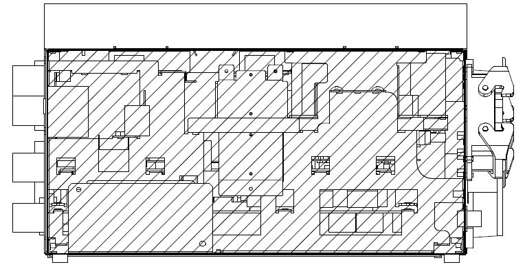
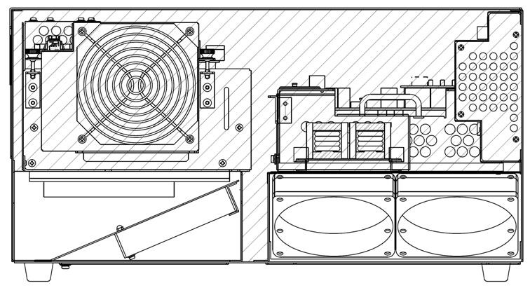
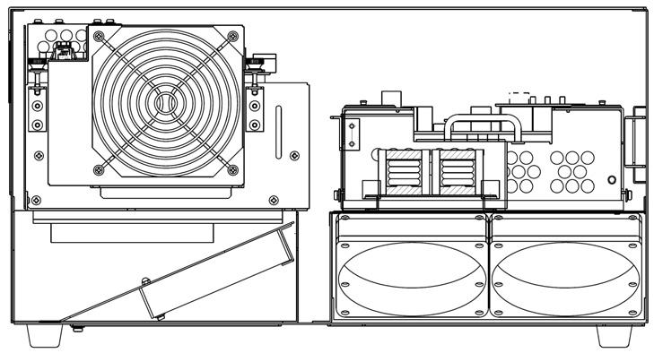
10 1. Safety E28 IP22 IP54 IP22 IP22 Front view (without door) Right side view E70/E71/E73/E74/E76/E77 IP20 IP54 Left side view Right side view E91 IP54 E94/E97 IP20 IP20 9 IP20
11 1. Safety 6. Free from flammable and/or corrosive liquid and gas. 7. Free from excessively strong vibration. 8. Place where power is supplied within specifications. 9. Place where dedicated earthing is provided. (100 or less) 10. Outside the safety fence with margin (min. 1 m) from the motion range of robot arm (with tools and workpieces).! CAUTION The controller shall not be located inside of the robot s motion range/workcell/safety fence. In addition, ensure the followings: Enough space for easy access to the controller during maintenance Installing an entrance gate with a safety plug to the safety fence Referring the requirements established in each region for details of the safety fence (e.g. ISO , ISO , JISB , JISB , JISB ) Approx. 1 m Approx. 1 m Motion range of robot arm (tool and workpiece included) Mechanical stopper Mechanical stopper Approx. 1 m Approx. 1 m Gate with safety plug Approx. 1 m Safety fence Controller 10
12 1. Safety 1.3 PRECAUTIONS WHEN CONNECTING THE HARNESS Strictly observe the following precautions when connecting the robot arm with the robot controller.! WARNING In order to prevent accidents caused by electric shock, do not connect the external power until connections between the robot arm and robot controller are complete.! CAUTION 1. Be careful when connecting the harnesses. Be sure to use the correct harnesses. Using an incorrect harness, or forcing or misconnecting the harness may damage connectors or cause a break in the electrical system. 2. Prevent people or equipment (forklift etc.) from stepping on or riding over the signal and motor harnesses. Otherwise, the harness may become damaged or the electrical system may break. 3. Separate the harnesses from any nearby high voltage lines (min. 1 m apart). Do not bundle or run the harnesses in parallel with other power lines. Otherwise, the noise generated from power lines will cause malfunctions. 4. Even when the harnesses are long, do not bundle them winded or bended. Bundling the harness causes the heat to build up in the harness, resulting in over-heat and furthermore may cause fire. 1.4 PRECAUTIONS WHEN CONNECTING THE EXTERNAL POWER Strictly observe the following precautions when connecting the external power.! DANGER Before beginning the connection work, confirm that the external power supply for the controller is cut off at the source. To prevent external power from being turned ON accidentally, tag the breaker and indicate clearly that work is in progress. Or, assign a supervisor in front of the breaker until all the connections are complete. Connecting components while power is supplied is extremely dangerous and may cause electric shock. 11
13 1. Safety! WARNING 1. Confirm that the connected supplying power meets specifications shown on the rating plate and the label attached on the side of the breaker. Supplying out-of-specification power will damage electric components in the controller. 2. Earth the controller to prevent against electrical noise and shock. 3. Use dedicated earth wire (100 or less), which is equal to or larger than the recommended power cable size ( mm 2 ). 4. Never share an earth line with workpiece to be welded or another machine (weld machine, etc.). 5. In arc welding applications, connect the minus pole of the weld power supply to a jig or directly to workpiece to be welded. Insulate the robot body and controller so that they do not share a common earth line. 6. Without fail, before turning ON the external power to controller, make sure the power supply wiring is complete and all the covers reattached properly. Otherwise, failure to do so may cause electric shock.! CAUTION 1. Prepare external power that meets the specifications of the controller in terms of momentary power interruption, voltage fluctuation, power capacity, etc. If the power is interrupted or the voltage goes out of the controller s specified range (above/below ratings), then the power monitoring circuit activates cutting off the power, and an error is returned. 2. If the external power emits a lot of electrical noise, set up a noise filter to reduce the interference. 3. PWM noise from robot motor lines may cause malfunction of low noiseresistant devices via external power line. Confirm that there are no such devices in the vicinity. 4. Install a separate external power switch (breaker) for the robot, independent and unconnected to the weld machine. 5. To prevent shorting or accidental leakage on the external power switch, install an earth leakage breaker. (Use a time delay type with sensitivity of 100 ma or more.) 6. If there is a possibility that surge voltage such as lightning surge might be applied from external power line, decrease the surge voltage level by mounting a surge absorber. NOTE* Proximity switch directly connected with power line etc. may suffer from the influence. 12
14 1. Safety 1.5 WARNING LABEL FOR ELECTRIC SHOCK Warning labels for electric shock are located on the controller s shown below. E1x controller The terminals are alive even when the controller power switch is OFF. Controller power switch DC power supply (AVR) Servo amplifier MC unit Front (Door omitted) 13


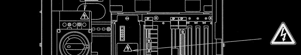


15 1. Safety E2x (exc E28) controller The terminals are alive even when the controller power switch is OFF. Controller power switch DC power supply (AVR) Servo amplifier MC unit Front (Door omitted) 14
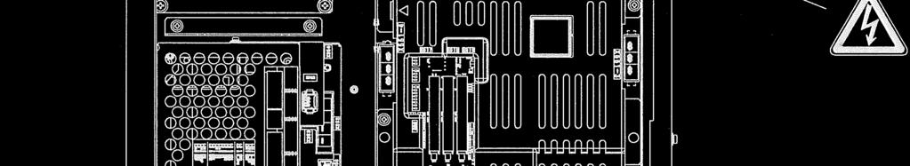
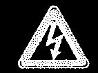
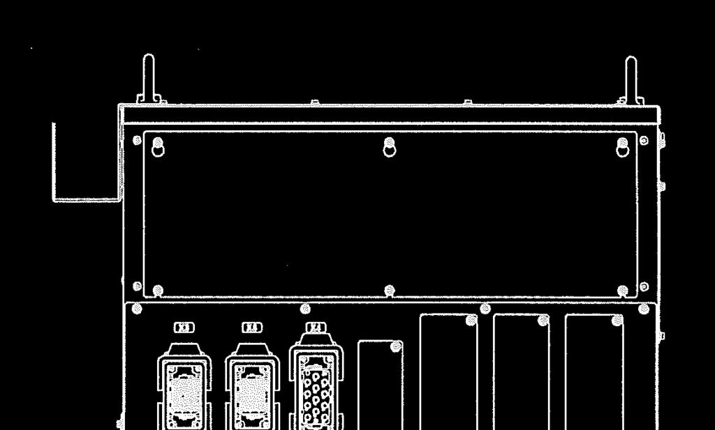
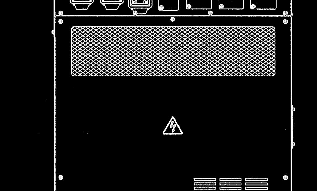
16 1. Safety E28 controller Cooler Controller power switch Transformer Additional Front regenerative Right Rear resistor unit The terminals are alive even when the controller power switch is OFF. Single-axis amp. unit DC power supply (AVR) MC unit Servo amp. MC unit Front (Door omitted) 15 Right


17 E3x controller 1. Safety The terminals are alive even when the controller power switch is OFF. Controller power switch DC power supply (AVR) MC unit Servo amplifier Front (Door omitted) 16
18 1. Safety Transformer Left Rear Top 17


")

 18")
19 1. Safety E4x controller Controller power switch The terminals are alive even when the controller power switch is OFF. DC power supply (AVR) MC unit Servo amplifier Front (Door omitted) 18


20 1. Safety Transformer Transformer Left Rear 19


21 1. Safety E7x controller Left DC power supply (AVR) External power input connector Rear Power unit MC Top Controller power switch The terminals are alive even when the controller power switch is OFF. 20


22 1. Safety E9x controller Controller power switch DC power supply (AVR) Servo amplifier Front External power input connector Capacitor Power unit Rear Controller power switch: The terminals are alive even when the controller power switch is OFF. Top Power unit Power unit Regenerative resistor Servo amplifier Top Left Bottom 21


23 1. Safety Connector plates on arm base section YF003N R series 03N/05N/05L R series 10N/06L R series 20N/10L R series30n/50n/80n/15x 22


24 1. Safety ZH ZX/ZT/ZD MT B Series MX/MD MG 23
25 1. Safety 1.6 BATTERY AND FUSE USE AND DISPOSAL Batteries are used for data backup in the robot mechanical unit and controller. Figures on the next page show the location of the batteries on the 1TA/1VA board and the 1FG/1HG boards. Batteries for 1FG/1HG board can be handled without removing connector plate on robot base, only with removing the plate indicating BATTERY shown in figure on the next page (bottom). If not used and disposed of properly, these batteries may malfunction, ignite, overheat, explode, corrode, leak, etc. Always use and dispose of all batteries in compliance with the following warnings and cautions. Figure on the page after next shows the location of fuse F1 (1.0 A, 125 V/250 V) on the 1TR board.! WARNING 1. Only use batteries specified by Kawasaki. 2. Never re-charge, dismantle, convert and/or overheat batteries. 3. Never dispose of batteries into water or fire. 4. Batteries with damaged cases may short internally and must not be used. 5. Never short the positive and negative poles of a battery with material such as wire.! CAUTION Never dispose of depleted batteries with garbage that is disposed of in an incinerator, land-fill, dumping-ground, etc. When disposing of batteries, insulate with tape so as not to contact other metal. Comply with local regulations and rules for battery disposal. 24
26 1. Safety Locations of Batteries 1TA/1VA board (in Card Rack) Location Number: E1 Model: BR2032 Manufacturer: Panasonic E1 1FG board (in Robot Base) Location Number: BAT1 Model: or Manufacturer: KHI Connector: CN10 CN10 BAT1 1HG board (in Robot Base) Location Number: BAT1 Model: or Manufacturer: KHI Connector: CN3 1FG board CN3 1HG board BAT1 Battery plate Connector plate on robot base 25
27 1. Safety Location of Fuse 1TR board (in Card Rack) Location Number: F1 Rating: 1.0A 125/250V UL Listed type F1 1.7 SAFETY FEATURES 1TR board To safeguard the user, Kawasaki robot systems are equipped with many safety features, including the following: 1. All E-stops are hard-wired. 2. All robot controllers are equipped with a redundant dual channel safety circuit. Both channels of the safety circuit must be closed to allow for robot operation in the teach and repeat modes. 3. Safety circuits of E28/E3x/E76/E77/E97 and E4x/E70/E71/E91/E94 controllers satisfy requirements of PLd in category 3 defined by ISO Category and Performance level (PL) are determined by the whole system and conditions. 4. (For E3x/E76/E77/E97 controllers) When the servo ON lamp (located on the mechanical unit) is illuminated, servo motor power is available to the robot and motion is possible. 5. The teach pendant and operation panel are equipped with red mushroom-type E-stop switches. And all robot controllers have external E-stop inputs. 6. The teach pendant is equipped with three-position, enabling devices. The enabling devices must be pressed to enable motor power in teach and check modes. 7. Teach and check mode velocities are limited to a maximum of 250 mm/s (10.0 in/s). 8. The velocities are not limited to 250 mm/s (10.0 in/s) in the Fast Check Mode that satisfy requirements for ISO (E28/E4x/E70/E71/E91 controllers: Standard, E1x/E2x (exc E28)/E73/E74/E94 controllers: Option) 9. Optional overtravel limit switches are available on JT1, JT2 and JT3 of the arm. See the specifications of the product for details. 10. Mechanical units have overtravel hardstops on the JT1, JT2 and JT3 (optional for JT2 and JT3) axes. Mechanical hardstops are capable of stopping the robot at full speed and with maximum payload. See the specifications of the product for details of the mechanical hard stops. 11. All robot axes are equipped with 24 VDC electromechanical brakes that engage when power is removed. If the robot loses power unexpectedly, the mechanical unit arm is held in position by the brakes. 26

 shown in the top figure on next page to the position shown in the figure.")

28 1. Safety 1.8 EMERGENCY MOVEMENT WITHOUT DRIVE POWER The manual brake release switches allow the operator to move individual robot axes without using motor power for maintenance and emergency situations. (E1x/E2x (exc E28)/E7x/E9x controllers: Option, E28/E3x/E4x controllers: Standard) The manual brake release switches are located; E1x/E2x controllers: Inside the door on the controller If the optional brake release switches are not equipped, connect the brake release box (option) shown in the top figure on next page to the position shown in the figure. E3x controller: Under the access door on the controller E4x controller: Inside the door on the controller E7x/E9x controllers: Front of the controller! WARNING When no servo power is applied, electromagnetic brakes lock to maintain the robot arm posture. Unsupported axes may fall when the brake release switch is pressed. Axes which are overhung, particularly JT2 and JT3, will fall down the fastest, depending on robot position, weight of the end-of-arm tooling, and wrist axis position. Position yourself to observe the entire robot arm and keep your eyes on the arm when operating this switch. E1x controller E2x (exc E28) controller Manual brake release switches (optional) 27
29 1. Safety Brake release box E1x controller E2x controller Brake release switch connecting port (X315) Brake release switches of E28 controller 28


30 1. Safety Brake release switches of E3x controller Brake release switches of E4x controller BRAKE Brake release switch connecting port Brake release panel Brake release switch connecting port of E7x controller 29
31 1. Safety Accessory panel Brake release switch connecting port Brake release switch connecting port of E9x controller Connecting port of brake release switch is provided at the position shown in the figure. Brake release switch box is the option. Brake release box 30
. Robot arm support To manually release axes brakes follow the procedure below. 1. Set motor power OFF. 2.")
32 1. Safety! WARNING To prevent injury to persons or damage to robotic equipment provide suitable support for the robot arm, end-of arm tooling and payload, before using a brake release switch. The robot arm can be supported overhead using a sling and an overhead crane (see figure below). Robot arm support To manually release axes brakes follow the procedure below. 1. Set motor power OFF. 2. Ensure all personnel are clear of site and all safety precautions are followed. 3. Provide suitable support of the robot arm, end-or-arm tooling, and payload if there is a risk of personal injury (see above figure). 4. Open the access door to the manual brake release switches. 5. Ensure the switches are in the OFF position and in operating condition. 6. Press the brake release switch of the axis to release for a moment, and confirm that the brake will not be released. 31
33 1. Safety 7. Press and hold the RELEASE ENABLE switch (see lower right figure). If the brake is released at this time, do not use the switch (see CAUTION). 8. Press the manual brake release switch for the axis to release the brake (see lower right figure). 9. The brake remains released until the brake release switch is released. 10. After using the brake release switches, close the access door.! CAUTION Stop using the manual brake release switch immediately if the electromagnetic brake is released by pressing only one switch. The switch may be defective. RELEASE ENABLE Switch Robot brake release axes Manual brake release SW 32
34 2. Workflow - Robot Controller Installation and Connection 2.0 WORKFLOW - ROBOT CONTROLLER INSTALLATION AND CONNECTION This workflow describes only the robot controller. For the robot arms, refer to the separate manuals for them. Examine installation place (including earth) environment Refer to 3.0 Appearance and specification of robot controller. Prep. work Confirm power supply voltage and power capacity Refer to 3.0 Appearance and specification of robot controller. Transport robot controller Refer to 4.0 Transportation of robot controller. Arrange and install robot controller Refer to 5.0 Arrangement of robot controller. Actual work Connect Teach Pendant and separate harness Refer to 6.0 Connection instructions. See also Installation and Connection Manual for robot arms. Connect peripheral control devices and equipment Refer to 8.0 Connection of peripheral control equipment. Connect external power Refer to 7.0 Connection of external power. 33
35 2. Workflow - Robot Controller Installation and Connection Turn ON controller power and confirm Note: See External I/O Manual for external control power supply. Work after connecting robot controller with the robot Turn ON motor power and confirm Confirm operation of robot arm and tool (Teach mode) Note: To use external emergency stop, see External I/O Manual. Refer to Operation Manual. Confirm other various functions Refer to Operation Manual. Work completed [ NOTE ] This manual only describes procedures from installation place examination to connection with external power. 34
36 3. Appearance and Specification of Robot Controller 3.0 APPEARANCE AND SPECIFICATION OF ROBOT CONTROLLER 3.1 CONTROLLER APPEARANCE 550 External power inlet Controller power switch 550 Lifting eyebolt Accessory panel Operation panel Hook Teach pendant connector 1200 Teach pendant Coin lock Left Front Right E10 controller 35 Rear USB port RS-232C port Connectors for separate harnesses (See section 6.1 for details.) Connecting ports in the accessory panel
37 3. Appearance and Specification of Robot Controller 550 External power inlet Controller power switch 550 Lifting eyebolt Accessory panel Operation panel Hook Teach pendant connector 1200 Teach pendant Coin lock Left Front USB port Right Rear E12 controller RS-232C port Connectors for separate harnesses (See section 6.1 for details.) Connecting ports in the accessory panel 36
38 3. Appearance and Specification of Robot Controller External power inlet Controller power switch Lifting eyebolt Accessory panel Operation panel Hook Teach pendant connector 1200 Teach pendant Coin lock Left Front USB port Right Rear RS-232C port Connectors for separate harnesses (See section 6.1 for details.) Connecting ports in the accessory panel E13 controller 37
39 3. Appearance and Specification of Robot Controller 550 External power inlet Controller power switch 550 Lifting eyebolt Accessory panel Operation panel Hook Teach pendant connector 1200 Teach pendant Coin lock Left Front USB port Right Rear E14 controller (MX) RS-232C port Connectors for separate harnesses (See section 6.1 for details.) Connecting ports in the accessory panel 38
40 3. Appearance and Specification of Robot Controller External power inlet Controller power switch Lifting eyebolt Accessory panel Operation panel Hook Teach pendant connector 1200 Teach pendant Coin lock Left Front USB port Right Rear E14 controller (MD) RS-232C port Connectors for separate harnesses (See section 6.1 for details.) Connecting ports in the accessory panel 39
41 3. Appearance and Specification of Robot Controller External power inlet Controller power switch Lifting eyebolt Accessory panel Operation panel Hook Teach pendant connector 950 Teach pendant Left Coin lock Front Connectors for separate harnesses (See section 6.1 for details.) USB port RS-232C port Right Rear E20 controller Connecting ports in the accessory 40
42 3. Appearance and Specification of Robot Controller External power inlet Controller power switch Lifting eyebolt Accessory panel Operation panel Hook Teach pendant connector 950 Teach pendant Coin lock Left Front USB port Right Rear RS-232C port Connectors for separate harnesses (See section 6.1 for details.) Connecting ports in the accessory panel E22 controller 41
43 3. Appearance and Specification of Robot Controller External power inlet Controller power switch Lifting eyebolt Accessory panel Operation panel Hook Teach pendant connector 950 Teach pendant Coin lock Left Front Connectors for separate harnesses (See section 6.1 for details.) USB port RS-232C port Right Rear E23 controller Connecting ports in the accessory panel 42
44 3. Appearance and Specification of Robot Controller External power inlet Controller power switch Lifting eyebolt Accessory panel Operation panel Hook Teach pendant connector 950 Teach pendant Coin lock Left Front USB port RS-232C port Right Rear Connectors for separate harnesses (See section 6.1 for details.) Connecting ports in the accessory panel E24 controller (MX) 43
45 3. Appearance and Specification of Robot Controller External power inlet Controller power switch Lifting eyebolt Accessory panel Operation panel Hook Teach pendant connector 950 Teach pendant Coin lock Left Front USB port RS-232C port Right Rear E24 controller (MD) Connecting ports in the accessory panel Connectors for separate harnesses (See section 6.1 for details.) 44
46 3. Appearance and Specification of Robot Controller Eye bolt External power inlet Controller power switch Accessory panel Operation panel Hook Coin lock Teach pendant Left Teach pendant connector Connector for additional controller harness Connectors for separate harnesses (See section 6.1 for details.) Front USB port RS-232C port E28 controller Connecting ports in the accessory panel 45
47 3. Appearance and Specification of Robot Controller External power inlet Controller power switch Brake release switch Lifting eyebolt Accessory panel Operation panel Teach pendant cable hook Hook Teach pendant connector 1200 Teach pendant Coin lock Left Front USB port RS-232C port Connecting ports in the accessory Right E30 controller Rear Connectors for separate harnesses (See section 6.1 for details.) 46
48 3. Appearance and Specification of Robot Controller External power inlet Controller power switch Lifting eyebolt Accessory panel Operation panel Brake release switch Hook Teach pendant cable hook Teach pendant connector 1200 Teach pendant Coin lock Left Front USB port RS-232C port Right Connectors for separate harnesses (See section 6.1 for details.) Rear Connecting ports in the accessory panel E32 controller 47
49 3. Appearance and Specification of Robot Controller External power inlet Teach pendant cable hook Lifting eyebolt Accessory panel Operation panel 1200 Controller power switch Brake release switch Hook Teach pendant connector Teach pendant Coin lock Left Front Connectors for separate harnesses (See section 6.1 for details.) USB port RS-232C port Right E33 controller Rear Connecting ports in the accessory panel 48
50 3. Appearance and Specification of Robot Controller External power inlet Controller power switch Lifting eyebolt Accessory panel Operation panel Brake release switch Teach pendant cable hook Hook Teach pendant connector 1200 Teach pendant Coin lock Left Front Connectors for separate harnesses (See section 6.1 for details.) USB port RS-232C port Connecting ports in the accessory panel Right Rear E34 controller (MX) 49
51 3. Appearance and Specification of Robot Controller External power inlet Teach pendant cable hook Lifting eyebolt Accessory panel Operation panel Hook 1200 Controller power switch Brake release switch Teach pendant connector Teach pendant Coin lock Left Front Connectors for separate harnesses (See section 6.1 for details.) USB port RS-232C port Connecting ports in the accessory panel Right Rear E34 controller (MD) 50
52 3. Appearance and Specification of Robot Controller 550 External power inlet Controller power switch 550 Lifting eyebolt Accessory panel Operation panel Hook Teach pendant connector 1200 Teach pendant Coin lock Left Front Connectors for separate harnesses (See section 6.1 for details.) USB port RS-232C port Connecting ports in the accessory panel Right Rear E40 controller 51
53 3. Appearance and Specification of Robot Controller 550 External power inlet Controller power switch 550 Lifting eyebolt Accessory panel Operation panel Hook Teach pendant connector 1200 Teach pendant Coin lock Left Front Right Rear USB port RS-232C port Connectors for separate harnesses (See section 6.1 for details.) Connecting ports in the accessory panel E42 controller 52
54 3. Appearance and Specification of Robot Controller External power inlet Controller power switch Lifting eyebolt Accessory panel Operation panel Hook Teach pendant connector 1200 Teach pendant Left Coin lock Front Right Rear USB port RS-232C port Connectors for separate harnesses (See section 6.1 for details.) Connecting ports in the accessory panel E43 controller 53
55 3. Appearance and Specification of Robot Controller 550 External power inlet Controller power switch 550 Lifting eyebolt Accessory panel Operation panel Hook Teach pendant connector 1200 Teach pendant Left Coin lock Front Connectors for separate harnesses (See section 6.1 for details.) USB port RS-232C port Right Rear E44 controller (MX) Connecting ports in the accessory panel 54
56 3. Appearance and Specification of Robot Controller External power inlet Controller power switch Lifting eyebolt Accessory panel Operation panel Hook Teach pendant connector 1200 Teach pendant Left Coin lock Front Connectors for separate harnesses (See section 6.1 for details.) USB port RS-232C port Right Rear E44 controller (MD) Connecting ports in the accessory panel 55
57 3. Appearance and Specification of Robot Controller Brake release panel Accessory panel Operation panel 250 Controller power switch 9 Left Teach pendant connector Front Connector for separate harness (See section 6.1 for details) Heat exchange fan Right External power input connector Rear USB port RS-232C port Brake release switch connecting port BRAKE Connecting ports in the accessory panel Connecting port in the brake release panel E70/E71 controllers 56
58 3. Appearance and Specification of Robot Controller Brake release panel Accessory panel Operation panel Left Teach pendant connector Front Controller power switch Connector for separate harness (See section 6.1 for details) Heat exchange fan Right External power input connector Rear USB port RS-232C port Brake release switch connecting port BRAKE Connecting ports in the accessory panel Connecting port in the brake release panel E73/E74 controllers 57


59 3. Appearance and Specification of Robot Controller Brake release panel Accessory panel Operation panel Controller power switch Left Teach pendant connector Front Connector for separate harness (See section 6.1 for details) Heat exchange fan Right External power input connector Rear USB port RS-232C port Brake release switch connecting port BRAKE Connecting ports in the accessory panel Connecting port in the brake release panel E76/E77 controllers 58

 Right External power input connector Rear Brake release switch")

60 3. Appearance and Specification of Robot Controller Accessory panel Operation panel Left Teach pendant connector Controller power switch Front Connector for separate harness (See section 6.1 for details) Right External power input connector Rear Brake release switch connecting port USB port RS-232C port Ethernet port* Connecting ports in the accessory panel E91 controller NOTE* The maximum length of the cable which can be connected to the Ethernet port is 30 m. 59

61 3. Appearance and Specification of Robot Controller Accessory panel Operation panel Left Teach pendant connector Controller power switch Front Connector for separate harness (See section 6.1 for details) Right External power input connector Rear Brake release switch connecting port USB port RS-232C port Ethernet port (option)* Connecting ports in the accessory panel E94/E97 controllers NOTE* The maximum length of the cable which can be connected to the Ethernet port is 30 m. 60

62 3. Appearance and Specification of Robot Controller 3.2 TEACH PENDANT APPEARANCE Teach lock switch Emergency stop switch Liquid crystal display Teach Pendant 61
63 3. Appearance and Specification of Robot Controller 3.3 CONTROLLER SPECIFICATION E1x/E2x (exc E28) controller Construction Self-sustaining fully closed, indirect cooling system E10, E12, E14 (MX): Approx. 120 kg (without transformer), Approx. 180 kg (with transformer) E20, E22, E24 (MX): Mass Approx. 95 kg, E13, E14 (MD): Approx. 135 kg (without transformer), Approx. 195 kg (with transformer) E23, E24 (MD): Approx. 110 kg Temperature 0-45 C Ambient Humidity %RH (Non condensing) environment Altitude Up to 1000 meters above mean sea level Pollution degree 3 or below AC V ±10 %, 50/60 Hz, 3 Phase AC V ±10 %, 50/60 Hz, Power source Option 3 Phase (with transformer, 200 V) (E1x controller) AC /440 V ±10 %, 50/60 Hz, 3 Phase (with transformer, 400 V) Power capacity Refer to the table below. Earthing Dedicated earthing (100 or less) Length of Teach pendant cable 5 m/10 m/15 m (10 m, 15 m are options.) Length of separate harnesses* 5 m/10 m/15 m (10 m, 15 m are options.) NOTE* Harness length between robot arm and controller Controller model Arm model Power capacity E10/E20 R series KVA Y series max. E12/E13/ R series KVA E22/E23 Z series max. MT series B series E14/E24 MX/MD series 10 KVA max. Recommended power cable size (Including earth wire) 3.5 mm 2 or more (AWG #12 or more) 5.5 mm 2 or more (AWG #10 or more) 5.5 mm 2 or more (AWG #10 or more) Length requirement 200 m or less 200 m or less 200 m or less 62
64 3. Appearance and Specification of Robot Controller Circuit breaker spec. for external power connection Controller model Rated current Rated voltage Rated interrupting capacity E1x (without 40 A AC230 V 7.5 ka (Icu) transformer)/e2x E1x (with 40 A AC230 V 7.5 ka (Icu) transformer, 200 V) E1x (with 20 A AC400 V 5 ka (Icu) transformer, 400 V) AC440 V 2.5 ka (Icu) 63
65 3. Appearance and Specification of Robot Controller E28 controller Construction Self-sustaining fully closed, indirect cooling system Mass E28: 280 kg, Temperature 0-45 C Ambient Humidity %RH (Non condensing) environment Altitude Up to 1000 meters above mean sea level Pollution degree 3 or below AC V±10 %, 50/60 Hz, 3 Phase (Japan spec) Power source AC V±10 %, 50/60 Hz, 3 Phase (Europe spec) AC V±10 %, 60 Hz, 3 Phase (North America spec) Power capacity Refer to the table below. Earthing Dedicated earthing (100 Ω or less) Length of Teach pendant cable 5 m/10 m/15 m (5 m, 15 m are options.) Length of separate harnesses* 5 m/7 m/10 m/15 m (5 m, 7 m, 15 m are options.) NOTE* Harness length between robot arm and controller. Controller model E28 Arm model MG series Power capacity 14.6 KVA max. Recommended power cable size (Including earth wire) 8.0 mm 2 (AWG #8) - 13 mm 2 (AWG #6) Length requirement 200 m or less Circuit breaker spec. for external power connection Controller model External power voltage Rated current Rated voltage Rated interrupting capacity E28 AC V 50 A AC 230 V 50 ka (Icu) AC V 50 A AC 400 V 30 ka (Icu) AC 415 V 30 ka (Icu) AC V 40 A AC 480 V 30 ka (UL489) 64
66 3. Appearance and Specification of Robot Controller E3x controller Construction Self-sustaining fully closed, indirect cooling system Mass E30: 145 kg, E32, E34 (MX): 180 kg, E33, E34 (MD): 195 kg Temperature 0-45 C Ambient Humidity %RH (Non condensing) environment Altitude Up to 1000 meters above mean sea level Pollution degree 3 or below Power source AC V±10 %, 60 Hz, 3 Phase AC V, V, 515 V, 575 V±10 %, Optional 50/60 Hz, 3 Phase AC V±10 %, 50/60 Hz, 3 Phase * Power capacity Refer to the table below. Earthing Dedicated earthing (100 or less) Length of Teach pendant cable 5 m/10 m/15 m (5 m, 15 m are options.) Length of separate harnesses* 5 m/7 m/10 m/15 m (5 m, 7 m, 15 m are options.) NOTE* Harness length between robot arm and controller. Controller Arm model model E30 R series Y series E32/E33 R series Z, MT series B series E34 MX/MD series Power capacity 4.9 KVA max. 9.9 KVA max. 9.9 KVA max. Recommended power cable size (Including earth wire) 3.5 mm 2 (AWG #12) (*: 5.5 mm 2 (AWG#10))- 13 mm 2 (AWG #6) 8.0 mm 2 (AWG #8) - 13 mm 2 (AWG #6) 8.0 mm 2 (AWG #8 or more) - 13 mm 2 (AWG #6) Length requirement 200 m or less 200 m or less 200 m or less Circuit breaker spec. for external power connection Controller External power Rated current Rated voltage Rated interrupting model voltage capacity E30 AC V 15 A AC 480 Y/277 V 30 ka (UL 489) AC 515/575 V 20 A AC 600 Y/347 V 18 ka (UL 489) AC V 40 A AC 240 Y 50 ka (UL 489) E32/33/34 AC V 20 A AC 480 Y/277 V 30 ka (UL 489) AC 515/575 V 20 A AC 600 Y/347 V 18 ka (UL 489) AC V 40 A AC 240 Y 50 ka (UL 489) 65
67 3. Appearance and Specification of Robot Controller E4x controller Construction Self-sustaining fully closed, indirect cooling system Mass E40: 145 kg, E42, E44 (MX): 180 kg E43, E44 (MD): 195 kg Temperature 0-45 C Ambient Humidity %RH (Non condensing) environment Altitude Up to 1000 meters above mean sea level Pollution degree 3 or below Power source AC V±10 %, 50/60 Hz, 3 Phase Power capacity Refer to the table below. Earthing Dedicated earthing (100 or less) Length of Teach pendant cable 5 m/10 m/15 m (5 m, 15 m are options.) Length of separate harnesses* 5 m/10 m/15 m (5 m, 15 m are options.) NOTE* Harness length between robot arm and controller. Controller model E40 E42/E43 E44 Arm model R series Y series R series Z series MT series B series MX/MD series Power capacity 4.9 KVA max. 9.9 KVA max. 9.9 KVA max. Recommended power cable size (Including earth wire) 3.5 mm 2 or more (AWG #12 or more) 5.5 mm 2 or more (AWG #10 or more) 5.5 mm 2 or more (AWG #10 or more) Length requirement 200 m or less 200 m or less 200 m or less Circuit breaker spec. for external power connection Controller model Rated current Rated voltage Rated interrupting capacity E40 10 A AC400 V 5 ka (Icu) AC415 V 2.5 ka (Icu) E42/43/44 20 A AC400 V 5 ka (Icu) AC415 V 2.5 ka (Icu) 66
68 3. Appearance and Specification of Robot Controller E7x controller Construction E70, E71, E73, E74, E76, E77: horizontal enclosed structure, indirect cooling system Mass E70, E71, E73, E74, E76, E77: 30 kg Temperature 0-45 C (0-40 C in vertical placing) Ambient Humidity %RH (Non condensing) environment Altitude Up to 1000 meters above mean sea level Pollution degree 3 or below Power source AC V±10 %, 50/60 Hz, Single phase Power capacity Refer to the table below. Earthing Dedicated earthing (100 or less) Length of Teach pendant cable 5 m/10 m/15 m (5 m, 15 m are options.) Length of separate harnesses* 5 m/10 m/15 m (5 m, 15 m are options.) NOTE* Harness length between robot arm and controller. Controller Arm model model E70/E73/E76 R series 03N E71/E74/E77 R series 05N/05L/06L/10N Power capacity 1.5 KVA max. 3.0 KVA max. Recommended power cable size (Including earth wire) mm 2 or more (AWG #14) mm 2 or more (AWG #14) Length requirement 200 m or less 200 m or less Circuit breaker spec. for external power connection Controller model Rated current Rated voltage Rated interrupting capacity E70/71/73/74 10 A AC250 V 1.5 ka (Icu) E76/77 10 A AC277 V 10 ka (UL 489) 67
69 3. Appearance and Specification of Robot Controller E9x controller E91: horizontal enclosed structure, indirect cooling Construction system E94, E97: horizontal open structure (Enclosed structure is an option.) Mass E91, E94, E97: 40 kg Temperature E91: 0-40 C E94, E97: 0-45 C (0-40 C for enclosed type) Humidity %RH (Non condensing) Ambient Altitude Up to 1000 meters above mean sea level environment E91: 3 or below Pollution degree E94, E97: 2 or below (3 or below for optional enclosed structure) Power source AC V±10 %, 50/60 Hz, Single phase Power capacity Refer to the table below. Earthing Dedicated earthing (100 or less) Length of Teach pendant cable E91, E97: 5 m/10 m/15 m (5 m, 15 m are options.) E94: 5 m/10 m/15 m (10 m, 15 m are options.) Length of separate harnesses* E91, E97: 5 m/10 m/15 m (5 m, 15 m are options.) E94: 5 m/10 m/15 m (10 m, 15 m are options.) NOTE* Harness length between robot arm and controller. Controller Arm model model E91/E94/E97 Y series R series 10L/20N Power Recommended power cable capacity size (Including earth wire) 5 KVA max. 3.5 mm 2 or more (AWG #12) Length requirement 200 m or less Circuit breaker spec. for external power connection Controller model Rated current Rated voltage Rated interrupting capacity E91 32 A AC250 V 10 ka (Icu) E94/E97 30 A AC277 V 10 ka (UL 489) 68
70 4. Transportation of Robot Controller 4.0 TRANSPORTATION OF ROBOT CONTROLLER When transporting the controller, strictly observe the precautions given in the sections below for whichever transport method is chosen. 4.1 BY CRANE LIFTING (E1X, E2X, E3X, E4X)! WARNING 1. Never support the controller manually when it is lifted up. And, never go under or stay too close to the controller during transport. 2. Hook the wire at the lifting eyebolts as shown below. 3. Ensure that the lifting eyebolts are not loose. Check each one and retighten if loose. Otherwise, the controller may fall and suffer damage. Wire Lifting eyebolt Hook 1 m or more! CAUTION 1. Prepare wire and crane capable of hoisting 300 kg or more, sufficient for a controller loaded with full options. 2. Remove the teach pendant and teach pendant holder (if equipped) before lifting with the wire sling. 3. Wire length: 1 m or more as shown in left figure. 4. Be careful as the controller may lean when lifted up. 5. Be careful not to let the wire snag on other equipment. E2x controller [ NOTE ] Transportation of E7x and E9x controllers by crane lifting is not possible. 69
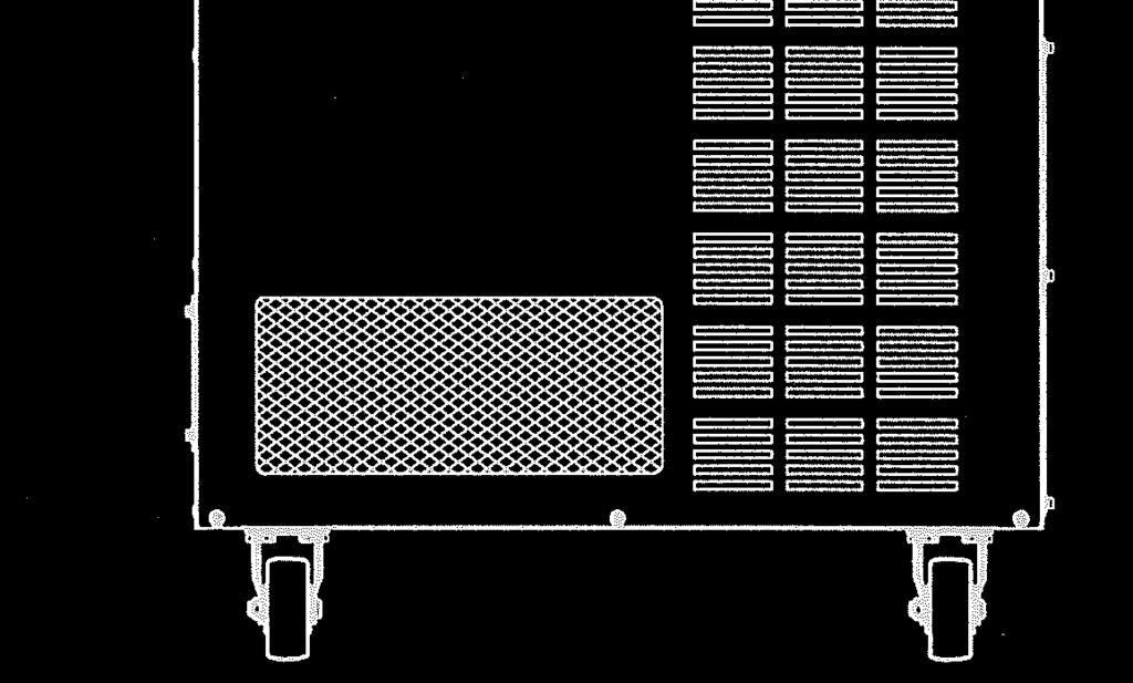
71 4. Transportation of Robot Controller 4.2 BY CASTER (E1X, E2X, E3X, E4X)! WARNING 1. If the transport path is flat enough then the controller can be moved on its casters. Otherwise, it may happen that moving on an incline or an uneven surface will topple the controller, and cause serious damage. 2. The E2x controller falls if it is inclined as follows. Back or forth: Approx. 20 (10 ) or more (10 is for E28 controller) Right or left: Approx. 15 or more The E1x/E3x/E4x controllers falls if it is inclined as follows. Back or forth: Approx. 15 or more Right or left: Approx. 15 or more! CAUTION 1. Release the stoppers on the two casters in front of the controller when moving the controller. (Push the OFF side pedal.) 2. Relock the casters after the transport is complete. (Push the ON side pedal for locking.) [ NOTE ] Transportation of E7x and E9x controllers by caster is not possible. 70
72 4. Transportation of Robot Controller 4.3 BY FORKLIFT TRUCK (E1X, E3X, E4X)! WARNING To stop the controller from toppling over, fasten it to the forklift with a belt as shown below. Falling prevention belt! CAUTION 1. Remove the teach pendant and teach pendant holder. The fork cannot be passed from the side. Pass the fork under the controller body as shown on the left. 2. Be careful not to shock the controller during transport. 3. Be careful not to get caught on other equipment, cables, etc. Pass the fork through this position. [ NOTE ] Transportation of E2x, E7x and E9x controllers by forklift is not possible. 71
73 4. Transportation of Robot Controller 4.4 BY TWO PERSONS (E7X, E9X)! CAUTION 1. Disconnect the Teach Pendant. 2. Be careful not to put an impact on the controller during transportation. 3. The clearance between the bottom of the controller and the floor is small (E7x: 9 mm, E9x: 18 mm). Accordingly, hold up one side of the controller then the other side, and get your fingers placed on the bottom of controller body sufficiently before holding up the controller. Because the controller has mass (E7x: 30 kg, E9x: 40 kg), it is impossible to carry the controller with fingertips. On the left side of E7x controller, handle is provided to hold up the controller. [ NOTE ] Transportation of E1x, E2x, E3x and E4x controllers by two persons is not possible. 72
74 5. Arrangement of Robot Controller 5.0 ARRANGEMENT OF ROBOT CONTROLLER In order for the controller to maintain the proper internal temperature, the installation site must conform to the four points below. 5.1 ARRANGEMENT OF E1X/E2X/E3X/E4X CONTROLLERS 1. Arrange the controller on a flat, horizontal floor. When an object is placed on the top surface of the controller, the mass should be 40 kg or less. 100 mm or more 100 mm or more 2. Separate the controller right/left side from the wall by 100 mm or more. 3. The inlet port for air-cooling is on the rear upside of the controller, and the air exhaust port is on the rear downside.! CAUTION Do not block the air inlet and exhaust ports when arranging the controller. Separate the controller backside from the wall by 200 mm or more mm or more 200 mm or more 4. Make fixing bracket(s), and fix the controller with M12 bolts. See the figure on next page for reference. 73


")
75 5. Arrangement of Robot Controller E2x (exc E28) controller E28 controller 74
76 5. Arrangement of Robot Controller E3x controller E1x/E4x controllers! CAUTION 1. Release the stoppers on the two casters in front of the controller when moving the controller. (Push the OFF side pedal.) 2. Relock the casters after the transport is complete. (Push the ON side pedal for locking.) 75
77 5. Arrangement of Robot Controller 5.2 ARRANGEMENT OF E7X/E9X CONTROLLERS Horizontal arrangement is the standard for E7x and E9x controllers. Follow the procedure below to arrange the controllers. For the E9x controller with the enclosed structure, the ambient temperature should be between 0-40 C. 1. Arrange the controller on a flat, horizontal floor. An object cannot be placed on the top surface of E7x controller. When an object is placed on the top surface of E9x controller, the mass should be 40 kg or less. It is possible to place an E9x controller on another E9x controller as far as the mass goes. However, when an object is placed on the top surface of E9x controller, it is necessary to remove the object once in maintenance. 2. Separate the controller right/left side from the wall by 100 mm or more. 3. Separate the controller top surface from the wall by 200 mm or more. 200 mm or more 100 mm or more 100 mm or more 4. Heat exchange fan is provided on the rear of the E7x controller.! CAUTION Do not block the air inlet and exhaust ports when arranging the E7x controller. For the E7x controller, separate the controller backside from the wall by 300 mm or more, leaving enough space for the separate harness to be bent. 200 mm or more E7x: 300 mm or more E9x: 200 mm or more 76
78 5. Arrangement of Robot Controller Follow the procedure below when arranging E7x/E9x controllers vertically. The ambient temperature should be within 0-40 C when arranging the E7x controller vertically. For the E9x controller, feet attached on the bottom of the controller can be reattached on the right side. An object cannot be placed on the top surface of the controller when the controllers are placed vertically. 100 mm or more 100 mm or more 200 mm or more 1. Arrange the controller on a horizontal floor. Arrange the controller with its controller power switch facing downward. 2. Separate the controller right side (top surface when placing the controller vertically) from the wall by 200 mm or more. 3. Separate the controller top/left side from the wall by 100 mm or more. 4. Separate the controller rear side from the wall by 300 mm or more for E7x controller and 200 mm for E9x controller. 5. If needed, make metal fittings as shown in the figure on the next page to fix the controller. 100 mm or more E7x: 300 mm or more E9x: 200 mm or more 77

79 5. Arrangement of Robot Controller E7x controller Rubber lining Metal fittings E9x controller Fixing bracket Height from ground plane to fixing hole: approx. 44 mm Fixing screw: M4 Fixing bracket Height from ground plane to fixing hole: approx. 25 mm Fixing screw: M4 NOTE: Replace foot rubbers together with fixing screws when the foot rubbers on the bottom are attached on the right side. If the screw with mark is too long, change it to the screw whole length is 6 mm or less when changing the screw. Otherwise, internal parts may be damaged. 78
80 6. Connection Instructions 6.0 CONNECTION INSTRUCTIONS 6.1 CONNECTION BETWEEN CONTROLLER AND ROBOT! WARNING Do not connect the external power until connections between controller and robot are complete. Accidents, such as electric shock may occur.! CAUTION 1. When connecting the harnesses, be sure to use the correct harnesses. Using an incorrect harness, or forcing or misconnecting the harness may damage connectors or cause a break in the electrical system. 2. Prevent people or equipment (forklift etc.) from stepping on or riding over the signal and motor harness lines. Otherwise, the harness may become damaged or the electrical system may break. 3. Even when the harnesses are long, do not bundle them winded or bended. Bundling the harness causes the heat to build up in the harness, resulting in over-heat and furthermore may cause fire. 4. Separate the harnesses from any nearby high voltage lines (min. 1 m apart). Do not bundle or run the harnesses in parallel with other power lines. Otherwise, the noise generated from power lines will cause malfunctions. 5. Separate the motor harness from the communication and sensor cables, and distribute the lines so they are neither bundled nor running in parallel. Moreover, connect the communication and sensor cables using shield mesh wire that includes twisted pair lines and connect the mesh wire to an adequate FG terminal. Otherwise, PWM noise radiated from the robot s motor drive lines may penetrate into various cables, such as communication cable and cause communication errors. 6. Separate the welder secondary cable from the robot s signal harness. Do not wire them in the same duct. 7. The motor harness (power line) between the robot and controller will generate PWM noise due to the PWM control driving the motors. This noise may cause interference with signal lines. Prevent interference using these countermeasures: (1) Separate the power and signal lines as much as possible. (2) Use the shortest possible length for the power line. (3) Avoid bundling, wiring in parallel the power and signal lines as much as possible. (4) Do not wire the power and signal line within the same duct/conduit. (5) Set and secure a firm earth line connection for the controller. 79
 Signal harness (X3) Major axis motor harness (X4) Wrist axis motor harness (X5) Signal harness (X3) E10 controller E12/E13 controllers Wrist axis motor")

81 6. Connection Instructions Connect the separate harnesses to their designated ports as shown below. 1. Controller side Motor harness (X4) Signal harness (X3) Major axis motor harness (X4) Wrist axis motor harness (X5) Signal harness (X3) E10 controller E12/E13 controllers Wrist axis motor harness (X4-2) Major axis motor harness (X4-1) Brake and JT7 motor harness (X5) Signal harness (X3) E14 controller! CAUTION 1. Fix each connector securely. The robot may malfunction if connectors loosen or detach. 2. The harness should drop straight down from the connector. Because connectors are located at the upper part of controller, the controller might topple over if the connected harnesses are pulled to the controller side or to the rear direction. 80
82 6. Connection Instructions Motor harness (X4) Signal harness (X3) Major axis motor harness (X4) Wrist axis motor harness (X5) Signal harness (X3) E20 controller E22/E23 controllers Wrist axis motor harness (X4-2) Major axis motor harness (X4-1) Brake and JT7 motor harness (X5) Signal harness (X3) Signal harness (X3B) Major axis motor harness (X4B-2) Major axis motor harness (X4B-1) Wrist axis motor+ brake harness (X5B) E24 controller E28 controller! CAUTION 1. Fix each connector securely. The robot may malfunction if connectors loosen or detach. 2. The harness should drop straight down from the connector. Because connectors are located at the upper part of controller, the controller might topple over if the connected harnesses are pulled to the controller side or to the rear direction. 81
 Signal harness (X3) E30 controller E32/E33 controllers Wrist axis motor harness (X4-2)")


83 6. Connection Instructions Motor harness (X4) Signal harness (X3) Major axis motor harness (X4) Wrist axis motor harness (X5) Signal harness (X3) E30 controller E32/E33 controllers Wrist axis motor harness (X4-2) Major axis motor harness (X4-1) Brake and JT7 motor harness (X5) Signal harness (X3) E34 controller! CAUTION 1. Fix each connector securely. The robot may malfunction if connectors loosen or detach. 2. The harness should drop straight down from the connector. Because connectors are located at the upper part of controller, the controller might topple over if the connected harnesses are pulled to the controller side or to the rear direction. 82
84 6. Connection Instructions Motor harness (X4) Signal harness (X3) Major axis motor harness (X4) Wrist axis motor harness (X5) Signal harness (X3) E40 controller E42/E43 controllers Wrist axis motor harness (X4-2) Major axis motor harness (X4-1) Brake and JT7 motor harness (X5) Signal harness (X3) E44 controller! CAUTION 1. Fix each connector securely. The robot may malfunction if connectors loosen or detach. 2. The harness should drop straight down from the connector. Because connectors are located at the upper part of controller, the controller might topple over if the connected harnesses are pulled to the controller side or to the rear direction. 83
85 6. Connection Instructions X4 X3 Signal harness Motor harness Keep space for reasonable treatment of harnesses with straight connectors. E7x controller Motor harness (X4) E9x controller Signal harness (X3)! CAUTION Fix each connector securely. The robot may malfunction if connectors loosen or detach. 84
86 6. Connection Instructions 2. Arm side YF003N X4A X3A Signal harness (Cable radius: mm) Motor harness (Cable radius: mm) 85
 X4A Motor harness (Cable radius: 20.2-22 mm) X3A Signal harness (Cable radius: 15.5-17.6 mm) R series 20N/10L X4A X3A Signal harness (Cable radius: 15.5-17.6 mm) Motor harness (Cable radius: 20.")
87 6. Connection Instructions R series 03N/05N/05L R series 10N/06L X401 Motor harness (Cable radius: mm) Signal harness (Cable radius: mm) X4A Motor harness (Cable radius: mm) X3A Signal harness (Cable radius: mm) R series 20N/10L X4A X3A Signal harness (Cable radius: mm) Motor harness (Cable radius: mm) 86
88 6. Connection Instructions R series 30N/50N/80N/15X X4A X5A X3A Signal harness (Cable radius: mm) Wrist axis motor harness (Cable radius: mm) Major axis motor harness (Cable radius: mm) ZH X5A X4A X3A Signal harness (Cable radius: mm) Major axis motor harness (Cable radius: mm) Wrist axis motor harness (Cable radius: mm) 87
89 6. Connection Instructions B series X4A X5A X3A Major axis motor harness (Cable radius: mm) ZX/ZT/ZD Signal harness (Cable radius: mm) Wrist axis motor harness (Cable radius: mm) X5A X4A X3A Signal harness (Cable radius: mm) Major axis motor harness (Cable radius: mm) Wrist axis motor harness (Cable radius: mm) 88
90 6. Connection Instructions MT X5A X4A X3A Major axis motor harness (Cable radius: mm) Wrist axis motor harness (Cable radius: mm) Signal harness (Cable radius: mm) MX/MD X5A X4A 2 X4A 1 X3A Signal harness (Cable radius: mm) Major axis motor harness (Cable radius: mm) Wrist axis motor harness (Cable radius: mm) Brake and JT7 motor harness (Cable radius: mm) 89
91 6. Connection Instructions MG X4BA-2 X3BA X5BA X4BA-1 Major axis motor harness (Cable radius: mm) Signal harness (Cable radius: mm) Major axis motor harness (Cable radius: mm) Wrist axis motor + brake harness (Cable radius: mm) 90

 Hook Teach pendant connector (X1)!")
92 6. Connection Instructions 6.2 CONNECTION BETWEEN CONTROLLER AND TEACH PENDANT 1. Connect the teach pendant cable with the connector, lower of operation panel. Pull up the lever and insert the cable side connector, then pull down the lever to lock the connectors. 2. Hang the teach pendant and the teach pendant cable on the hook. (No hook is provided for E7x/E9x controllers.) Hook Teach pendant connector (X1)! CAUTION The hook should only be used for hanging the teach pendant or cable. This figure shows E2x controller. Teach pendant connector E7x/E9x controllers (This figure shows E7x controller.) 91
93 7. Connection of External Power 7.0 CONNECTION OF EXTERNAL POWER Strictly observe the following precautions when connecting the external power.! DANGER Before beginning the connection work, confirm that the external power supply for the controller is cut off at the source. To prevent external power from being turned ON accidentally, tag the breaker and indicate clearly that work is in progress. Or, assign a supervisor in front of the breaker until all the connections are complete. Connecting components while power is supplied is extremely dangerous and may cause electric shock.! WARNING 1. Confirm that the connected supplying power meets specifications shown on the rating plate and the label attached on the side of the breaker. Supplying out-of-specification power will damage electric components in the controller. 2. Earth the controller to prevent against electrical noise and shock. 3. Use dedicated earth wire (100 or less), which is equal to or larger than the recommended power cable size ( mm 2 ). 4. Never share an earth line with workpiece to be welded or another machine (weld machine, etc.). 5. In arc welding applications, connect the minus pole of the weld power supply to a jig or directly to workpiece to be welded. Insulate the robot body and controller so that they do not share a common earth line. 6. Without fail, before turning ON the external power to controller, make sure the power supply wiring is complete and all the covers reattached properly. Otherwise, failure to do so may cause electric shock. 92
94 7. Connection of External Power! CAUTION 1. Prepare external power that meets the specifications of the controller in terms of momentary power interruption, voltage fluctuation, power capacity, etc. If the power is interrupted or the voltage goes out of the controller s specified range (above/below ratings), then the power monitoring circuit activates cutting off the power, and an error is returned. 2. If the external power emits a lot of electrical noise, set up a noise filter to reduce the interference. 3. PWM noise from robot motor lines may cause malfunction of low noise- resistant devices via external power line. Confirm that there are no such devices in the vicinity. 4. Install a separate external power switch (breaker) for the robot, independent and unconnected to the weld machine. 5. To prevent shorting or accidental leakage on the external power switch, install an earth leakage breaker. (Use a time delay type with sensitivity of 100 ma or more.) 6. If there is a possibility that surge voltage such as lightning surge might be applied from external power line, decrease the surge voltage level by mounting a surge absorber. NOTE* Proximity switch directly connected with power line etc. may suffer from the influence. 93

95 7. Connection of External Power E1x/E2x/E4x controllers Connect the external power according to the following procedure. Connect with the external power circuit breaker at the installation site. CONTROLLER POWER switch 1. Turn OFF the external power for the controller. 2. Set CONTROLLER POWER switch on the controller door to the OFF side. 3. Feed the external power cable into the inlet on the left side of controller. External power inlet Detailed procedure of fixing a cable is shown below. Cut a cable gland (supplied with the controller) in accordance with the diameter of the cable. NOTE*: If the cable diameter is more than 19, prepare a seal connector which is appropriate for the cable diameter. The hole diameter of the plate is 34. Pass the cable through the cable gland. Tighten the screw after adjusting length of the cable. Pass the cable through the inlet and tighten the lock nut. Cable gland ~ Inside Outside Tightening screw Cable 9-12 ~ Controller enclosure Lock nut Cutting position ( xx: diameter of cable)! CAUTION 1. Confirm current requirements and select a power cable with adequate capacity. (See section 3.0.) 2. Do not install wire that is too small in diameter, the voltage may drop or the cable may overheat. 94
96 7. Connection of External Power External power cable A Lock detent Earth wire 4. Attach round, crimp-type terminals on the ends of the individual wires of the power cable. Use round insulators on each of these wires to prevent contact between the crimped part and metal. (See left figure.) Breaker screw Connect the earth wire to the earth terminal as shown below. E2x controller View A-A E1x/E4x controllers External power cable connection terminal cover A Earth terminal Earth terminal 5. Connect the external power cable to the breaker terminal (3 screws), and the dedicated earth terminal.!! WARNING Tighten the terminal screws securely. Operating the robot with loose terminals is very dangerous and may lead to electric shock, robot malfunction, or breakdown of the electrical system. [ NOTE ] As to E1x/E2x controllers without insulation transformer, make sure to connect earth phase S to the center terminal in the case of connecting external power to the breaker. If not, the earth leakage breaker might trip. 6. Mount the external power cable connection terminal cover. DANGER Mount the external power cable connection terminal cover when the wiring is complete. Failing to mount the cover may lead to electric shock due to accidental contact with power line. View A-A Electric cable size Crimp-type terminal size to be used Breaker Earth terminal 3.5 mm 2 (AWG12) R5.5-5 R mm 2 (AWG10) 8 mm 2 (AWG8) R8-5 R mm 2 (AWG6) R14-5 R
97 7. Connection of External Power E3x controller Connect with the external power circuit breaker at the installation site. Connect the external power according to the following procedure. 1. Turn OFF the external power for the controller. External power inlet CONTROLLER POWER switch OFF position 2. Set CONTROLLER POWER switch on the left front of the controller to the OFF position. 3. Feed the external power cable into the inlet on the top of the controller with following procedures. Lock nut Inside Plate Cable gland (Seal connector) Prepare the cable gland that is suitable for the power cable diameter. Remove the plate on external power inlet, and make a hole for the cable gland. Pass the cable through the cable gland. Tighten the nut after adjusting length of the cable. Pass the cable through the inlet and tighten the lock nut. Hole Outside Nut Power cable! CAUTION 1. Confirm current requirements and select a power cable with adequate capacity. (See section 3.0.) 2. Do not install wire that is too small in diameter, the voltage may drop or the cable may overheat. 96

, and connect the external power cable to the breaker terminal (3 screws), and the dedicated earth terminal.")

98 7. Connection of External Power Earth wire Breaker screw Cover mounting screw Earth terminal External power cable A External power cable connection terminal cover Lock detent A 4. Attach round, crimp-type terminals on the ends of the individual wires of the power cable. Use crimp-type terminal, UL listed type shown in the table below. The crimp-type terminal should be crimped with appropriate tools in accordance with manufacturer s instruction manual. 5. Attach the plate on external power inlet. 6. Unscrew the cover mounting screws, remove the breaker terminal cover (upper side), and connect the external power cable to the breaker terminal (3 screws), and the dedicated earth terminal. Connect the ground wire with the ground terminal as shown left figure. After wiring, return the cover as it was.! WARNING Tighten the terminal screws securely. Operating the robot with loose terminals is very dangerous and may lead to electric shock, robot malfunction, or breakdown of the electrical system. View A-A! DANGER Mount the external power cable connection terminal cover when the wiring is complete. Failing to mount the cover may lead to electric shock due to accidental contact with power line. 97
99 7. Connection of External Power External power voltage: AC V, AC , AC , AC515, AC575V Crimp-type terminal size Electric cable size to be used (Use the UL listed terminal) Breaker Earth terminal 3.5 mm 2 (AWG12) R5.5-8 R mm 2 (AWG10) 8 mm 2 (AWG8) R8-8 R mm 2 (AWG6) R14-8 R
100 7. Connection of External Power E7x/E9x controllers Connect the external power according to the following procedure. Connect with the external power circuit breaker at the installation site. E7x controller 1. Turn OFF the external power for the controller. 2. Set CONTROLLER POWER switch on the front of the controller to the OFF position without fail. 3. Connect the external power cableto the external power connector on the rear of the controller. External power connector E9x controller Solder the attached connector on the external power cable. The figure below shows pin configuration of connector. D C A B A B C D AC(L) (N.C.) AC(N) FG Wiring diagram of attached connector! CAUTION 1. Confirm current requirements and select a power cable with adequate capacity. (See section 3.0.) 2. Do not install wire that is too small in diameter, the voltage may drop or the cable may overheat. 99
101 7. Connection of External Power 7.1 CHANGE OF EXTERNAL POWER INPUT VOLTAGE (ONLY FOR E1X/E3X CONTROLLERS WITH OPTIONAL TRANSFORMER) Change the connection of the transformer connector before changing the external power input voltage. Specification External power input voltage Connector E1x series (optional) 380/400 V X601A /440 V 440 V X601B Specification External power input voltage Connector 380/400/415 V X601A E3x series (optional) 440/460/480 V X601B / /515/575 V 515 V X601C 575 V X601D Specification External power input voltage Connector 200/220 V X601A E28 controller 380/400/415 V X601B 440/460/480 V X601C To change the connection, remove the bottom panel on the back side of the cabinet. 100
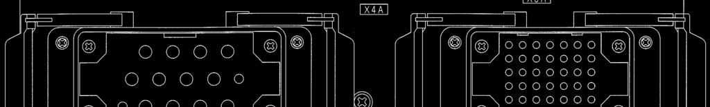
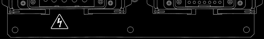
102 8. Connection of Peripheral Control Equipment 8.0 CONNECTION OF PERIPHERAL CONTROL EQUIPMENT According to application specifications, connect the peripheral controller or devices to the respective connectors in the controller as shown below. E2x controller Cable support Use cable support for wiring of 24Vdc or less such as I/O, Ethernet and fieldbus cable etc. Make sure not to put any stress on connectors on each board. 1TA/1VA Board Screw to connect external I/O Cable shield (M4) 1TR Board 1TW Board Terminal block X7 Connector Terminal block X8 Connector Terminal block X9 Connector External D-I/O Connector CN2 (Output) External D-I/O Connector CN4 (Input) See the right figure for details on connecting ports of 1TA/1VA board. RS-232C port* USB port* Ethernet port NOTE*: The upper RS-232C port and the upper USB port are connected to each port in the accessory panel for standard specification. 101
103 8. Connection of Peripheral Control Equipment E1x/E3x/E4x controllers 1TA/1VA Board Cable support Screw to connect external I/O Cable shield (M4) 1TR Board 1TW Board External D-I/O Connector CN2 (Output) Terminal block X7 Connector Terminal block X8 Connector External D-I/O Connector CN4 (Input) Terminal block X9 Connector Use cable support for wiring of 24Vdc or less such as I/O, Ethernet and fieldbus cable etc. Make sure not to put any stress on connectors on each board. See the right figure for details on connecting ports of 1TA/1VA board. RS-232C port* USB port* Ethernet port NOTE*: The upper RS-232C port and the upper USB port are connected to each port in the accessory panel for standard specification. 102
104 8. Connection of Peripheral Control Equipment E7x controller Rear I/O signal inlet Connect each connecting port with peripheral equipment and devices, using the I/O signal inlet on the rear or the left side of the controller. Left External D-I/O Connector CN2 (Output) External D-I/O Connector CN4 (Input) 1TW Board 1TR Board 1TA/1VA Board AVR Terminal block X9 Terminal block X8 Terminal block X7 Left See the right figure for details on connecting ports of 1TA/1VA board. RS-232C port * USB port * Ethernet port NOTE*: The left RS-232C port and the left USB port are connected to each port in the accessory panel for standard specification. 103


 Terminal")


105 8. Connection of Peripheral Control Equipment E9x controller I/O signal inlet Connect each connecting port with peripheral equipment and devices, using the I/O signal inlet on the rear side of the controller. AVR External D-I/O Connector CN2 (Output) Terminal block X7 Terminal block X8 Terminal block X9 1VA Board 1TR Board External D-I/O Connector CN4 (Input) 1TW Board Top See the right figure for details on connecting ports of 1VA board. RS-232C port* USB port* Ethernet port NOTE*: The left RS-232C port and the left USB port are connected to each port in the accessory panel for standard specification. 104
106 8. Connection of Peripheral Control Equipment 8.1 CONNECTION INSTRUCTIONS! WARNING Turn OFF the power supply to the controller and peripheral equipment when connecting external I/O. Prevent accidental turn ON of the power until all connections are complete by take procedures shown below or by tagging the breaker to indicate that work is in progress or by assigning a supervisor to stand in front of the breaker. Failure to do so is extremely dangerous and may result in electric shock or damage to the electrical system. Controller model Procedure to prevent turning ON the power during operations E1x/E2x/E3x/E4x Padlock the main breaker handle. E70/E71/E73/E74 Mount the attached lock part or disconnect the external power connector. E76/E77/E91/E94/E97 Lock by attached lock fitting or padlock, or disconnect the external power connector.! CAUTION 1. Take the necessary noise countermeasures on equipment with external I/O connections to the controller. Electrical noise that interferes with the I/O signals may cause malfunction or damage to the electrical system. 2. Do not mistake pin Nos. on the connectors when connecting external I/O. Misconnecting pins may cause breakdown of the electrical system. 3. Prevent people or equipment (forklift, objects, etc.) from stepping on or riding over the external I/O cables. An unprotected cable may become damaged causing breaks in the electrical system. 4. Avoid wiring the external I/O cables and the power lines close together or in parallel as much as possible. Separate the cables and lines by at least 20 cm. (either in or outside the controller) Electromagnetic induction noise from the robot motor cable, the power lines for peripheral equipment, welding cable, etc. may penetrate into the I/O cables and lead to malfunction. 5. Use a shield cable for the external I/O cable and connect the shield wire to the controller. 6. When connecting I/O cables to connectors or terminals, fix them with tying bands in the harness support set on the top of the controller, preventing them from excessive force. (pulling, snagging of cable, etc.) 7. Install the seal connector so that external I/O cables never cause insulation failure or disconnection at the inlet. 105
107 8. Connection of Peripheral Control Equipment 8.2 CONNECTION OF GENERAL PURPOSE SIGNAL The robot can operate synchronously with the peripheral equipment or other robots when connecting I/O signals to the peripheral controller with connectors CN2 and CN4 on the 1TW board. (Connectors on the cable side of CN2 and CN4 are optional.) 1. Insert the cables into I/O signal inlet. I/O signal inlet: Left side of the controller for E1x/E2x/E3x/E4x, rear or left side of the controller for E7x, rear of the controller for E9x An example of installing the cable(s) is shown below. (1) Make a hole in the plate suitable for the seal connector. (2) Pass the cable through the seal connector (3) After passing the cable to the hole, tighten the nut(s) of the seal connector. plate seal connector inside hole outside E9x controller cable I/O signal inlet * I/O signal inlet * This figure shows E2x controller. E7x controller 2. Remove the connector cover for CN2 and CN4, and wire for general purpose signal. 3. Solder the connector pin after putting the insulation tube through the electric cable. 4. Strip off the cable coating by 2-3 mm and apply solder to the wire end. 5. Solder the cable to the connector pin. 106
108 8. Connection of Peripheral Control Equipment [ NOTE ] On the plate part shown with *, cables can be put through by mounting commercial cable entry (manufactured by PHOENIX CONTACT, KEL cable entry system). 6. Cover the connector pin with the insulation tube. [ NOTE ] 1. Use an insulation tube of heat shrinkage type, or bind the tube ends on each line so they do not come off. 2. We recommend using AWG22-24 or equivalent for cables. 7. After wiring is complete, attach connector cover and fix the cable securely. 107
![8. Connection of Peripheral Control Equipment 8. Insert the connector into 1TW board and fix with locking screws at both ends. [ NOTE ] Tighten the screw thoroughly.](/docs-images/89/97667560/images/109-0.jpg "The connection may fail if the screw is loose and the connector pins are exposed to excessive stress/force.")
 or equivalent CN4: DC-37P-NR (JAE) or equivalent Stripped wire 2-3 mm Cable clamp Cover DC19678-3R (JAE) or equivalent Harness Insulation")
109 8. Connection of Peripheral Control Equipment 8. Insert the connector into 1TW board and fix with locking screws at both ends. [ NOTE ] Tighten the screw thoroughly. The connection may fail if the screw is loose and the connector pins are exposed to excessive stress/force. Cover 17JE-37H2-1A-CF (DDK) or equivalent Harness Stripped wire 2-3 mm Insulation tube Connector Connector pin CN2 17JE (D1)A (DDK) or equivalent CN4 17JE (D1) (DDK) or equivalent E1x/E2x/E3x/E4x controllers Connector CN2: DC-37S-NR (JAE) or equivalent CN4: DC-37P-NR (JAE) or equivalent Stripped wire 2-3 mm Cable clamp Cover DC R (JAE) or equivalent Harness Insulation tube Locking screw CN2: D JR (JAE) or equivalent: M2.6 CN4: D JR (JAE) or equivalent: M2.6 Connector pin E7x/E9x controllers 108
110 8. Connection of Peripheral Control Equipment 8.3 CONNECTION OF HARDWARE DEDICATED SIGNAL It is possible to construct a safety circuit using the hardware circuit by connecting the external emergency stop signal or hold signal line to the terminal connector on the 1TR board. Refer to External I/O Manual for more details about signals and their connection to each terminal block. Terminal block connections are held in place by springs. Push a thin flat-head screwdriver (width: 2.5 mm or less) into the hole on the right to open the spring in the left hole. Then insert the wire there to connect. 1TR Board X7 Connector (X8 Connector) (X9 Connector) We recommend using AWG22-24 or equivalent for cables. (Stripped wire length: 7 mm) To assure the wiring, we recommend using ferrules; Recommended model: (WAGO) Recommended crimping tool: (WAGO) (Stripped wire length: 9.5 mm) Connection side Insert driver for connection 8.4 CONNECTION OF PERSONAL COMPUTER A PCcan be used as a terminal for the robot controller, when loaded with tetminal softwares KRterm/KCwin32 and connected to the RS-232C port in the accessory panel. Also a PC loaded with KRterm /KCwin TCPIP can be used as terminal by connecting it to the ethernet port on 1TA/1VA board with Ethernet cable. Refer to the AS Language Reference Manual for more details. 8.5 CONNECTION OF RS-232C SERIAL SIGNAL (OPTION) Data communication is possible with the host computer when the host computer is connected to the RS-232C port on the 1TA/1VA board with an RS-232C cable. Refer to the option manual DE* for details. 8.6 CONNECTION OF ETHERNET COMMUNICATION SIGNAL (OPTION) It is possible to build an Ethernet LAN of 10BaseT/100BaseTX using the ethernet port on 1TA/1VA board. Refer to the option manual DE* for details. 109
111 8. Connection of Peripheral Control Equipment 8.7 CONNECTION OF FIELDBUS (OPTION) Adding the 1TJ/1UK board for fieldbus (option) enables communication with peripheral devices such as DeviceNet on the fieldbus. Refer to the option manual DE* for details. 8.8 CONNECTION OF SENSORS/VALVES ON ARM (OPTION) Input from sensors mounted on arm and control of output of driving energy to the valves become available by adding arm ID and machine I/O boards, such as 1PV, 1JD, 1JE, 1TK and 1TY boards. Refer to the option manuals DE* and DE* for details. 8.9 COOLER DRAIN PIPING OF E28 CONTROLLER The E28 controller is equipped with a cooler and the drain water is discharged during the operation. Carry out the drain piping following the procedure shown below. 1. Connect a drain hose to the drain pipe located on the back side of the cooler. 2. Make sure to connect hoses to both the main and secondary drain pipes. 3. Fix the drain hose, the drain pipe, and the L-shaped pipe using a tying band as shown in the figure below. *Make sure that the clamp for the tying band faces upward. Cooling coil Main drain pan Main drain pipe L-shaped pipe Drain pipe Hose Drain pipe Hose Auxiliary drain pan Secondary drain pipe To the polyethylene container or a drain outlet *Drain water flows continually in the main drain pipe. Make sure to connect it to a polyethylene container or a drain outlet. *The secondary drain pipe is a drain pipe for emergency use when the main drain pipe is blocked with something. 110


112 8. Connection of Peripheral Control Equipment PRECAUTIONS TO BE TAKEN DURING DRAIN PIPING <Appropriate piping method of drain water> 1. The cooler has the double drain pan structure as a measure against water leakage, however, the water may leak if the piping is not carried out following the procedure below. In addition, the drain water is unable to be drained in the pipe with drain trap. Trap shape 2. If discharging the drain water by linking two drain pipes into one, the drain water may flow backward or leak. Make sure to arrange the main drain pipe and secondary drain pipe separately. 3. Make sure that the corner section to which an L-shaped pipe is connected is not raised. Always use a hose of appropriate length, and fasten it with a hose band, etc. Do not set the L-shaped pipe higher than the drain port. 4. The drain hose must be arranged as shown below. *When storing the drain water in a container, do not immerse the hose in the water. <Correct> <Incorrect> *If the hose is immersed in the water, the drain water does not flow smoothly. <Incorrect> <Incorrect> *The drain water is dropped naturally, so be sure to set the hose in such a way that the water can drain smoothly. If the hose sags or is blocked somewhere, the drain water will not be discharged smoothly. 111
Installation and Connection Manual
 F Series Installation and Connection Manual Kawasaki Heavy Industries, Ltd. 90202-1183DEB Preface Preface This manual describes the installation and connection of the controller. This manual covers the
Installation and Connection Manual
 E Series (Explosion-proof type) Installation and Connection Manual Kawasaki Heavy Industries, Ltd. 90202-1111DEG PREFACE This manual describes the installation and connection of the E series controllers.
Standard specifications RS007LFF60
 Standard specifications RS007LFF60 December 05, 2017 KAWASAKI HEAVY INDUSTRIES, LTD. ROBOT DIVISION Materials and specifications are subject to change without notice. Specification : (Arm): (Controller):
HITACHI. EH-150 series PLC EH-RTD8 Resistance Temperature Detective input module Instruction manual. Safety precautions
 HITACHI EH-150 series PLC Resistance Temperature Detective input module Instruction manual Thank you for purchasing a Hitachi Programmable Logic Controller. To operate it safely, please read this instruction
Installation Job Aid for VSP 4850GTS
 Installation Job Aid for VSP 4850GTS Notices Release 6.1.0.0 NN46251-308 Issue 02.01 November 2017 Notice paragraphs alert you about issues that require your attention. The following paragraphs describe
Installation Job Aid for VSP 4450GTX-HT- PWR+
 Installation Job Aid for VSP 4450GTX-HT- PWR+ Notices Release 6.1.0.0 NN46251-305 Issue 02.01 November 2017 Notice paragraphs alert you about issues that require your attention. The following paragraphs
NIR Moisture Analyzer KB-30
 NIR Moisture Analyzer KB-30 Operation Manual Safety Precautions FPL950701 Improper use of the NIR moisture analyzer in violation of the following safety notes may result in death, injury or damage to property
H Series PLC. ! : Indicates Compulsion. EH-150 Analog input module EH-AXH8M Instruction manual. Safety precautions DANGER CAUTION COMPULSION
 H Series PLC EH-150 Analog input module EH-AXH8M Instruction manual Thank you for purchasing a Hitachi Programmable Logic Controller. To operate it safely, please read this instruction manual and all the
MDM 011-Z1 Regen Resistor
 MDM 011-Z1 Regen Resistor Date of creation: 10.04.2017 Version date: 10.04.2017 Article number: 09-402-011-Z1-E Publisher: SIGMATEK GmbH & Co KG A-5112 Lamprechtshausen Tel.: 06274/4321 Fax: 06274/4321-18
Standard specifications BA006LFE01C01
 Standard specifications BA006LF01C01 ###### 1st dition : August 30, 2016 KAWASAKI HAVY INDUSTRIS, LTD. ROBOT DIVISION Materials and specifications are subject to change without notice. Specification :
Standard specifications MC20-01-AX20 MC10L-01-AX20
 Standard specifications MC20-01-AX20 MC10L-01-AX20 8th edition 0912, SMCEN-017-008,001 Table of contents 1. Outline...1 1.1. MC robot... 1 1.2. AX20 controller...1 2. Characteristic...2 2.1. MC robot...
JANOME DESKTOP ROBOT JR2000N Series. Operation Manual. <Setup> For Qualified Installer ONLY
 JANOME DESKTOP ROBOT JR2000N Series Operation Manual For Qualified Installer ONLY Thank you for purchasing the Janome Robot. *Read this manual thoroughly in order to properly use this robot. Be sure
ATS-16 HV USER MANUAL. Automatic Transfer Switch 16A / 230Vac V090318
 ATS-16 HV Automatic Transfer Switch 16A / 230Vac USER MANUAL V090318 SAFETY Intended use The ATS-16 HV device serves as a power source selector to provide improved power supply for connected loads. ATS-16
USP-070-B08 USP-104-B10, USP-104-M10 USP-156-B10
 UniStream HMI Panel Installation Guide USP-070-B10, USP-070-B08 USP-104-B10, USP-104-M10 USP-156-B10 Unitronics UniStream platform comprises control devices that provide robust, flexible solutions for
TABLE OF CONTENTS. Page 2 14
 TABLE OF CONTENTS INTRODUCTION... 3 WARNING SIGNS AND THEIR MEANINGS... 3 1. PRODUCT OVERVIEW... 4 1.1. Basic features and components... 4 1.2. Supply package... 5 1.3. Robot arm specifications... 6 1.4.
ELV12 Series. Instruction Manual
 Instruction Manual TDK-Lambda BEFORE USING POWER SUPPLY UNIT Be sure to read this instruction manual thoroughly before using this product. Pay attention to all warnings and cautions before using the unit.
TOP - 1. Instruction Manual. Version 1.0 Produced in Jan. 2004
 Version 1.0 Produced in Jan. 2004 Instruction Manual LCD monitor IV-08MP Thank you for purchasing the SHARP IV-08MP LCD monitor. Read this introductory instruction manual carefully to thoroughly familiarize
MC 11 EB-2 Power supply cabinet with external bus, AC version
 MC 11 EB-2 Power supply cabinet with external bus, AC version USER/MAINTENANCE MANUAL 1 SLOT 0 SLOT 1 SLOT 2 SLOT 3 SLOT 4 SLOT 5 SLOT 6 SLOT 7 SLOT 8 SLOT 9 SLOT 10 SLOT 11 EB-2 (a) MC11 (b) (c) Figures
When any of the following symbols appear, read the associated information carefully. Symbol Meaning Description
 Uni-I/O Modules Installation Guide UID-0808R, UID-0808T, UID-1600,UID-0016R, UID-0016T Uni-I/O is a family of Input/Output modules that are compatible with the UniStream control platform. This guide provides
PAR-WT50R-E PAR-WR51R-E
 Wireless Remote Controller and Receiver PAR-WT50R-E PAR-WR51R-E This manual explains installation of the PAR-WR51R-E wireless receiver and the PAR-WT50R-E wireless remote controller, and settings of these
High Speed Remote I/O Module
 High Speed Remote I/O Module EXF-RC15 The Unitronics EXF-RC15 is a High Speed Remote I/O Module that offers three High Speed Counter inputs and four high speed outputs. Overall, the EXF-RC15 offers 9 digital
EX-RC1 Remote I/O Adapter
 EX-RC1 Remote I/O Adapter The EX-RC1 interfaces between Unitronics Vision OPLCs and remote I/O Expansion Modules distributed throughout your system. The adapter is connected to a PLC via CANbus. Each adapter
Instruction book IQAN-LSL. Publ no HY /UK Edition 0301
 Instruction book IQAN-LSL Publ no HY17-8367/UK Edition 0301 Contents 1 Introduction......................................................2 2 Precautions.......................................................3
Part No. Z , IA Nov OPERATION MANUAL. High Voltage Digitalmeter A
 Part No. Z1-109-920, IA001723 Nov. 2005 OPERATION MANUAL High Voltage Digitalmeter 149-30A Use of Operation Manual Please read through and understand this Operation Manual before operating the product.
When any of the following symbols appear, read the associated information carefully. Symbol Meaning Description
 Uni-I/O Wide Modules Installation Guide UID-W1616R, UID-W1616T Uni-I/O Wide is a family of Input/Output modules that are compatible with the UniStream control platform. Wide Modules are 1.5 times as wide
RUC-M industrial relays for DC loads
 Contact data Number and type of contacts Contact material Rated / max. switching voltage Min. switching voltage Rated load Min. switching current Max. inrush current Rated current Min. breaking capacity
Rhino Buffer Module PSM24-BFM600S. Operating Instructions
 Rhino Buffer Module PSM24-BFM600S Operating Instructions RHINO BUFFER MODULE PSM24-BFM600S Description The PSM24-BFM600S Buffer Module will hold the output voltage of a 24 VDC power supply after brownouts
Part No. Z , IA Mar OPERATION MANUAL. High Voltage Digitalmeter A
 Part No. Z1-109-820, IA001704 Mar. 2011 OPERATION MANUAL High Voltage Digitalmeter 149-10A Use of Operation Manual Please read through and understand this Operation Manual before operating the product.
Installation Job Aid for Ethernet Routing Switch 3600 Series
 Installation Job Aid for Ethernet Routing Switch 3600 Series Notices NN47213-303 Issue 03.01 November 2017 Notice paragraphs alert you about issues that require your attention. Following are descriptions
Symmetra PX 160. Maintenance Bypass Enclosure. Installation 05/
 Symmetra PX 160 Maintenance Bypass Enclosure Installation 05/2014 www.schneider-electric.com Legal Information The Schneider Electric brand and any registered trademarks of Schneider Electric Industries
Motorized Curtain Tracks Progress 50 Motor Set
 Troubleshooting Before you decide that the trouble is a malfunction, perform the following check. Condition Not operating Unstable operation Moves adversely and in opposite direction Operation speed is
QUICK START GUIDE. vau4/3. Frequency converter. operating instructions /12
 operating instructions QUICK START GUIDE Frequency converter vau4/3 28100241101 12/12 1 Safety information Warning of electrical shock! Danger to life! Electrical shock can cause serious injury or even
OPLC Installation Guide
 Samba OPLC SM35-J-R20/SM43-J-R20 SM70-J-R20 SM35-J-T20/SM43-J-T20 SM70-J-T20 OPLC Installation Guide 12 Digital Inputs, include 1 HSC/Shaft-encoder Input, 2 Analog inputs (only when the digital inputs
Standard specifications MR20-02-AX20 MR20L-01-AX20
 Standard specifications MR20-02-AX20 MR20L-01-AX20 6th edition 0912, SMREN-017-006,001 Table of contents 1. Outline...1 1.1. MR robot... 1 1.2. AX20 controller...1 2. Characteristic...2 2.1. MR robot...
OPERATING INSTRUCTION
 OPERATING INSTRUCTION AUTORANGING MULTIMETER MAX Ω F C 10A MAX every 15 min. COM V SAFETY INFORMATION The following safety information must be observed to insure maximum personal safety during the operation
Preparing to Install the VG248
 CHAPTER 2 To ensure normal system operation, plan your site configuration and prepare your site before installation. Before installing the VG248, review these sections: Preparing the Installation Site,
PROGRAMMABLE CONTROLLER. FP0 A/D Converter Unit. Technical Manual ARCT1F321E
 PROGRAMMABLE CONTROLLER Technical Manual ARCT1F321E-2 2008.11 Safety Precautions Observe the following notices to ensure personal safety or to prevent accidents. To ensure that you use this product correctly,
IO-AO6X I/O Expansion Module 6 Isolated Analog Outputs
 IO-AO6X I/O Expansion Module 6 Isolated Analog Outputs The IO-AO6X is an I/O Expansion Module that can be used in conjunction with specific Unitronics OPLC controllers. The module offers 6 12-bit isolated
When any of the following symbols appear, read the associated information carefully. Symbol Meaning Description
 Uni-I/O Modules Installation Guide UID-0808THS Uni-I/O is a family of Input/Output modules that are compatible with the UniStream control platform. This guide provides basic installation information for
Manual Version: V1.00. Video Decoder Quick Guide
 Manual Version: V1.00 Video Decoder Quick Guide Thank you for purchasing our product. If there are any questions, or requests, please do not hesitate to contact the dealer. Copyright Copyright 2016 Zhejiang
Part No. Z , IA Jul OPERATION MANUAL. High Voltage Digitalmeter A
 Part No. Z1-109-820, IA001705 Jul. 2016 OPERATION MANUAL High Voltage Digitalmeter 149-10A Use of Operation Manual Please read through and understand this Operation Manual before operating the product.
RUC industrial relays of small dimensions
 with adaptor (V) with adaptor (H) Power relays of general application AC and DC coils Mounting: in sockets; 35 mm rail mount acc. to PN-EN 60715; on panel; PCB Versions: faston 187 (4,8 x 0,5 mm); faston
Important Information KX-NTV150. Communication IP Camera. IP Video Doorphone. Model No. Model No. KX-NTV160
 Important Information Communication IP Camera Model No. KX-NTV150 IP Video Doorphone Model No. KX-NTV160 Thank you for purchasing this Panasonic product. Please read this Important Information carefully
When any of the following symbols appear, read the associated information carefully. Symbol Meaning Description
 Uni-I/O Modules Installation Guide UIA-0402N Uni-I/O is a family of Input/Output modules that are compatible with the UniStream control platform. This guide provides basic installation information for
OPERATING INSTRUCTIONS PA AMPLIFIER P-1812
 OPERATING INSTRUCTIONS PA AMPLIFIER P-1812 Please follow the instructions in this manual to obtain the optimum results from this unit. We also recommend that you keep this manual handy for future reference.
Emerson Network Power provides customers with technical support. Users may contact the nearest Emerson local sales office or service center.
 Liebert PSA iton User Manual Version: V2.8 Revision date: November 14, 2005 Emerson Network Power provides customers with technical support. Users may contact the nearest Emerson local sales office or
CUS150M1 Instruction Manual
 BEFORE USING THE POWER SUPPLY UNIT Be sure to read this instruction manual thoroughly before using this product. Pay attention to all cautions and warnings before using this product. Incorrect usage could
EUROPE R-SERIES. up to 80 kg payload
 EUROPE R-SERIES up to 80 kg payload »Simple and friendly«into THE FUTURE»40 years of experience and state-of-the-art robot technology«the R-SERIES 1. High speed 4. Protection Kawasaki Robotics invents
The power behind competitiveness. Delta Infrasuite Power Management. Power Distribution Unit. User Manual.
 The power behind competitiveness Delta Infrasuite Power Management Power Distribution Unit User Manual www.deltapowersolutions.com Save This Manual This manual contains important instructions and warnings
Safety and Installation
 RC420 Safety and Installation Read this manual first Rev.2 EM089B1740F RC420 Safety and Installation Rev.2 RC420 Safety and Installation Rev.2 Copyright 2007-2008 SEIKO EPSON CORPORATION. All rights reserved.
Line reactors SINAMICS. SINAMICS G130 Line reactors. Safety information 1. General. Mechanical installation 3. Electrical installation
 Safety information 1 General 2 SINAMICS SINAMICS G130 Mechanical installation 3 Electrical installation 4 Technical specifications 5 Operating Instructions Control version V4.7 04/2014 A5E00331462A Legal
PLC-24V10AL(-PT/-TH) Quick Start Manual (Rev.1.10)
 Quick Start Manual (Rev.1.10)") TEC (Peltier) Controller PLC-24V10AL(-PT/-TH) Quick Start Manual (Rev.1.10) Thank you for purchasing the TEC (Peltier) Controller PLC-24V10AL. Read these operating instructions carefully to ensure effective
TEC (Peltier) Controller PLC-24V10AL(-PT/-TH) Quick Start Manual (Rev.1.10) Thank you for purchasing the TEC (Peltier) Controller PLC-24V10AL. Read these operating instructions carefully to ensure effective
RUC industrial relays of small dimensions
 Contact data Number and type of contacts Contact material Rated / max. switching voltage Min. switching voltage Rated load Min. switching current Max. inrush current Rated current Max. breaking capacity
High Power Electronic Gear Installation and operation Guide
 High Power Electronic Gear Installation and operation Guide 96268731 GT 1 KW 230-240 V HQITS-S DGE CLI WI SC 96267936 GT 2 KW 230-240 V HO/HF DGE CLI WI SC IP21 IP21 electronical gear for 1 and 2 kw HIT-DE
Autoranging True RMS Multimeter User Manual
 Autoranging True RMS Multimeter User Manual Please read this manual before switching the unit on. Important safety information inside. Contents Page 1. Safety Information... 4 2. Safety Symbols... 5 3.
Conductive Level Controller
 Conductive Level Controller 61F-D21T-V1 Ideal for level control for industrial facilities and equipment. Outputs can be set to self-hold at ON or OFF using self-holding circuits. Sensitivity adjustment
IO-DI8-TO8, IO-DI8-TO8-L I/O Expansion Modules 8 Inputs, 8 Outputs
 IO-DI8-TO8, IO-DI8-TO8-L I/O Expansion Modules 8 Inputs, 8 Outputs The IO-DI8-TO8 and IO-DI8-TO8-L are I/O expansion modules that can be used in conjunction with specific Unitronics OPLC controllers. The
Installation Manual INTELLIGENT SERVER. Model name: BMS-LSV6UL
 Model name: BMS-LSV6UL INTELLIGENT SERVER Thank you very much for purchasing this TOSHIBA INTELLIGENT SERVER. Please read this manual carefully beforehand for proper installation of the SERVER. NOTE This
Voltage Current Front-mounting bracket
 Switching Power Supply S8PS Compact DIN-Rail Mounting Industrial Power Supplies with Capacities Up to 600 W Models range from 0 W to 600 W. Universal input: voltage range 0 to 240 VAC. Power Factor Correction
V E1B Snap-in I/O Module
 V200-18-E1B Snap-in I/O Module The V200-18-E1B plugs directly into the back of compatible Unitronics OPLCs, creating a selfcontained PLC unit with a local I/O configuration. Features 16 isolated digital
Obtaining Documentation and Submitting a Service Request, page xvii Safety Warnings, page xvii Safety Guidelines, page xx
 Preface Obtaining Documentation and Submitting a Service Request, page xvii Safety s, page xvii Safety Guidelines, page xx Obtaining Documentation and Submitting a Service Request For information on obtaining
The following symbols are used to show dangerous operation or handling. Make sure you understand them before reading the guide.
 Safety Instructions Before use Thank you very much for purchasing this product. This product is an interface box called "Connection & Control Box" for EPSON short throw projectors. For your safety, read
S8VE (60/90/120/180/240-W Models)
") Switch Mode Power Supply S8VE (60/90/120/180/240-W Models) CSM_S8VE_DS_E_1_1 60/90/120/180/240-W Models Improved Versions of Standard-type Power Supplies without Indication Monitor. Safety standards: UL508/60950-1,
Switch Mode Power Supply S8VE (60/90/120/180/240-W Models) CSM_S8VE_DS_E_1_1 60/90/120/180/240-W Models Improved Versions of Standard-type Power Supplies without Indication Monitor. Safety standards: UL508/60950-1,
ATS22D17Q soft starter-ats22-control 220V-power 230V(4kW)/ V(7.5kW)
/ V(7.5kW)") Characteristics soft starter-ats22-control 220V-power 230V(4kW)/400...440V(7.5kW) Main Range of product Altistart 22 Product or component type Product destination Product specific application Component
Characteristics soft starter-ats22-control 220V-power 230V(4kW)/400...440V(7.5kW) Main Range of product Altistart 22 Product or component type Product destination Product specific application Component
CR2/CR2A/CR2B Controller INSTRUCTION MANUAL
 MITSUBISHI Mitsubishi Industrial Robot CR2/CR2A/CR2B Controller INSTRUCTION MANUAL Controller setup, basic operation, and maintenance BFP-A5991-J Safety Precautions Always read the following precautions
Model HM-535 Power Supply Installation and Service Instructions
 Model HM-535 Power Supply Installation and Service Instructions 430-535 0104 2004 Heritage MedCall, Inc SENTRY INSTALLATION & SERVICE INSTRUCTIONS POWER SUPPLY UNIT Model HM-535 IMPORTANT SAFETY INSTRUCTIONS
DIO-1616LN-FIT. Features. Specifications. Ethernet Remote I/O F&eIT N Series Isolated Digital Input/Output Unit DIO-1616LN-FIT 1. Ver.1.
 Ethernet Remote I/O F&eIT N Series Isolated Digital / DIO-1616LN-FIT * Specifications, color and design of the products are subject to change without notice. This product is an isolated digital input and
Series IZH10. Handheld Electrostatic Meter. How to Order. Accessories and Option / Part Number for Individual Parts.
 Peak G 15min Handheld Electrostatic Meter Series IZH10 How to Order IZH10 Option Nil H None High-voltage measuring handle Accessories and Option / Part Number for Individual Parts The ground wire and soft
Line Interactive 1000VA/1400VA/2000VA Uninterruptible Power System
 USER MANUAL Line Interactive 1000VA/1400VA/2000VA Uninterruptible Power System 614-06762-00 IMPORTANT SAFETY INSTRUCTIONS SAVE THESE INSTRUCTIONS This manual contains important instructions for Line Interactive
INSTRUCTION MANUAL TRIP CIRCUIT SUPERVISION RELAY GKAD1
 INSTRUCTION MANUAL TRIP CIRCUIT SUPERVISION RELAY GKAD1 TOSHIBA Corporation 2004 All Rights Reserved. ( Ver. 1.6 ) Safety Precautions Before using this product, please read this chapter carefully. This
B&W RearView Camera Installation & Operation
 B&W RearView Camera Installation & Operation CA52 (Camera) FOR MORE INFORMATION WWW.STRATEGICVISTA.COM BEFORE OPERATING THIS SYSTEM, PLEASE READ THIS MANUAL THOROUGHLY AND RETAIN IT FOR FUTURE REFERENCE
TOS-SN-1 Extended Panel Operation Manual
 Introduction TOS-SN-1 Extended Panel Operation Manual The Extended Panel (TOS-SN-1) for TOSVERT series inverter can be used for programming or monitoring, but does not contain internal memory. Please read
Replacing the Power Supply
 APPENDIX B This appendix includes information on how to replace the power supply for the Cisco AS550XM universal gateway and contains the following sections: Safety Recommendations, page B-1 Required Tools
Instruction Manual MINI CALIBRATOR MC-20
 Instruction Manual MINI CALIBRATOR MC-20 Introduction Thank you for purchasing the MINI CALIBRATOR MC-20. This manual contains operating, specifications and cautions, etc. Please ensure that you fully
The identified danger could cause physical and property damage.
 Samba OPLC SM35-J-T20 Installation Guide The Unitronics SM35-J-T20 offers the following onboard I/Os: 12 Digital Inputs, configurable via wiring to include 2 Analog and 3 HSC/Shaft-encoder Inputs 8 Transistor
Installation Guide V290 (Color) This guide provides basic information for Unitronics LCD color touchscreen models V C30B and V T40B.
 This guide provides basic information for Unitronics LCD color touchscreen models V C30B and V T40B.") Vision OPLC Installation Guide V290 (Color) This guide provides basic information for Unitronics LCD color touchscreen models V290-19-C30B and V290-19-T40B. General Description Vision OPLCs are programmable
Vision OPLC Installation Guide V290 (Color) This guide provides basic information for Unitronics LCD color touchscreen models V290-19-C30B and V290-19-T40B. General Description Vision OPLCs are programmable
DX200 OPTIONS MECHATROLINK-II COMMUNICATION FUNCTION INSTRUCTIONS
 DX200 OPTIONS MECHATROLINK-II COMMUNICATION FUNCTION INSTRUCTIONS (FOR MP2110-ET3 MADE BY YASKAWA ELECTRIC CORPORATION ) Upon receipt of the product and prior to initial operation, read these instructions
panasonic.net/id/pidsx/global CCD The sensor can be used for various applications with its binary data output with four different sensing modes.
 1123 PHOTO PHOTO PARTICUR Type Edge Sensor SERIES Related Information General terms and conditions... F-3 About laser beam... P.1593~ guide... P.1021~ General precautions... P.1595 Conforming to FDA regulations
V E2B Snap-in I/O Module
 V200-18-E2B Snap-in I/O Module The V200-18-E2B plugs directly into the back of compatible Unitronics OPLCs, creating a selfcontained PLC unit with a local I/O configuration. Features 16 isolated digital
S-14 S-14. Compact Digital Multimeter. Compact Digital Multimeter
 S-14 Compact Digital Multimeter S-14 Compact Digital Multimeter SAFETY INFORMATION The following safety information must be observed to insure maximum personal safety during the operation at this meter
This guide provides basic information for Unitronics Models 230/260/280/290 (Non-color Screens).
.") Vision OPLC Installation Guide Models 230/260/280/290 (Non-color Screens) This guide provides basic information for Unitronics Models 230/260/280/290 (Non-color Screens). General Description Vision OPLCs
Vision OPLC Installation Guide Models 230/260/280/290 (Non-color Screens) This guide provides basic information for Unitronics Models 230/260/280/290 (Non-color Screens). General Description Vision OPLCs
UniStream HMI Panel. CPU-for-Panel
 UniStream HMI Panel Installation Guide USP-070-B10,USP-104-B10, USP-156-B10 Unitronics UniStream platform comprises control devices that provide robust, flexible solutions for industrial automation. This
Optional add-on cassette Attachment Instruction manual
 E6580774 Optional add-on cassette Attachment Instruction manual 1. INTRODUCTION 3 2. CONNECTION TO THE INVERTER 4 2.1 Fixing the option alone 4 2.2 Connection to the inverter 6 3. SPECIFICATION 8 4. WARRANTY
FR-A8AR INSTRUCTION MANUAL
 INVERTER Plug-in option FR-A8AR INSTRUCTION MANUAL Relay output function PRE-OPERATION INSTRUCTIONS INSTALLATION AND WIRING RELAY OUTPUT 1 2 3 Thank you for choosing this Mitsubishi inverter plug-in option.
Owner s Manual. Isolate. Restore. Inspire! Power Conditioners Audio / Video Power Isolation Units Rack Mount / Consumer Series
 Owner s Manual 19 Pro Series Rack Mount (RK) Faceplate Isolate. 17 Consumer Series (C) Faceplate Available in Black (B) and Silver (S) Colours Restore. Power Conditioners Audio / Video Power Isolation
Vision OPLC V TR6/V350-J-TR6
 Vision OPLC V350-35-TR6/V350-J-TR6 Installation Guide The Unitronics V350-35-TR6/V350-J-TR6 offers the following onboard I/Os: 8 Digital Inputs, configurable via wiring to include 2 Analog (current/voltage)
Installation Sensing distance Connection Output configuration Operation mode NO Operation mode NC
 Standard (thin shape) Inductive Proximity Sensor Thin shape for space saving surface mounting Direct side wall mounting for bracket-less installation Ordering Information DC 3-wire Models Installation
LXM32SD18M2 motion servo drive - Lexium 32-single phase supply voltage 115/230V - 0.5/1.kW
 Product data sheet Characteristics LXM32SD18M2 motion servo drive - Lexium 32-single phase supply voltage 115/230V - 0.5/1.kW Main Range of product Lexium 32 Product or component type Device short name
ATS22D62Q soft starter-ats22-control 220V-power 230V(15kW)/ V(30kW)
/ V(30kW)") Characteristics soft starter-ats22-control 220V-power 230V(15kW)/400...440V(30kW) Main Range of product Altistart 22 Product or component type Product destination Product specific application Component
Characteristics soft starter-ats22-control 220V-power 230V(15kW)/400...440V(30kW) Main Range of product Altistart 22 Product or component type Product destination Product specific application Component
Wise HP33 THREE PHASE HIGH PRECISION AVR SURVO-MOTOR AUTOMATIC VOLTAGE STABILIZER
 Wise HP33 THREE PHASE HIGH PRECISION AVR SURVO-MOTOR AUTOMATIC VOLTAGE STABILIZER LEN.MAN.STA.111 Rev.4.00/2010 CONTENTS 1. SAFETY INSTRUCTIONS 1 2. INTRODUCTION 2 3. FRONT PANEL AND CONNECTION BOARD 3
The Flexible Heavy-Duty Robot
 The Flexible Heavy-Duty Robot up to kg payload Kawasaki Robotics (USA), Inc. THE FLEXIBLE HEAVY-DUTY ROBOT The high payload long reach Z-Series robots were developed using Kawasaki s advanced technology
Operating instructions AS-i SmartLine module AC3200 AC /00 06/2016
 Operating instructions AS-i SmartLine module AC3200 AC3201 80237876/00 06/2016 Contents 1 Preliminary note...3 1.1 Symbols used...3 1.2 Warnings used...3 2 Safety instructions...3 2.1 General...3 2.2 Target
VFI RTG PDU 6-10K. Installation and user manual. Service and support: Call your local service representative
 VFI RTG PDU 6-10K Installation and user manual Service and support: Call your local service representative SAFETY INSTRUCTIONS SAVE THESE INSTRUCTIONS. This manual contains important instructions that
Power Supply. Users Guide PRODUCT MANUAL. WESTELL.COM Westell Technologies MNL rd
 PRODUCT MANUAL Power Supply Westell Technologies. 960-1152-MNL rd DISCLAIMER All information and statements contained herein are accurate to the best of Westell Technologies knowledge. Westell Technologies
ATS22D17Q soft starter-ats22-control 220V-power 230V (4kW)/ V(7.5kW)
/ V(7.5kW)") Product datasheet Characteristics ATS22D17Q soft starter-ats22-control 220V-power 230V (4kW)/400...440V(7.5kW) Complementary Assembly style Function available Supply voltage limits Main Range of product
Product datasheet Characteristics ATS22D17Q soft starter-ats22-control 220V-power 230V (4kW)/400...440V(7.5kW) Complementary Assembly style Function available Supply voltage limits Main Range of product
DC-D2212R / DC-D2212WR
 Network Camera Quick Guide / DC-D2212WR Powered by Safety Precautions WARNING RISK OF ELECTRIC SHOCK DO NOT OPEN WARNING: TO REDUCE THE RISK OF ELECTRIC SHOCK, DO NOT REMOVE COVER (OR BACK). NO USER-SERVICEABLE
Safety Control. FS1A Multi-function Safety Relay. Optional Parts. Connecting Tool. Marked Cable Tie. DIN Rail BNDN1000 Aluminum, 1m 35mm wide
 Multi-function Relay Key features: No programming required. Configuration complete by turning on a logic switch A safety circuit can be configured easily just by selecting a logic from eight preprogrammed
DM-918 OPERATIONS MANUAL AUTORANGING MULTIMETER
 DM-918 OPERATIONS MANUAL AUTORANGING MULTIMETER SAFETY INFORMATION The following safety information must be observed to ensure maximum personal safety during the operation of this meter: This meter is
CM E FUJITSU SEMICONDUCTOR CONTROLLER MANUAL F 2 MC-16L/16LX EMULATION POD MB HARDWARE MANUAL
 FUJITSU SEMICONDUCTOR CONTROLLER MANUAL CM42-00411-2E F 2 MC-16L/16LX EMULATION POD MB2145-507 HARDWARE MANUAL F 2 MC-16L/16LX EMULATION POD MB2145-507 HARDWARE MANUAL FUJITSU LIMITED PREFACE Using the
AutoRanging Digital MultiMeter
 Owner's Manual AutoRanging Digital MultiMeter Model No. 82175 CAUTION: Read, understand and follow Safety Rules and Operating Instructions in this manual before using this product. Safety Operation Maintenance