Motor driver board. EB022
|
|
|
- Colin Welch
- 5 years ago
- Views:
Transcription

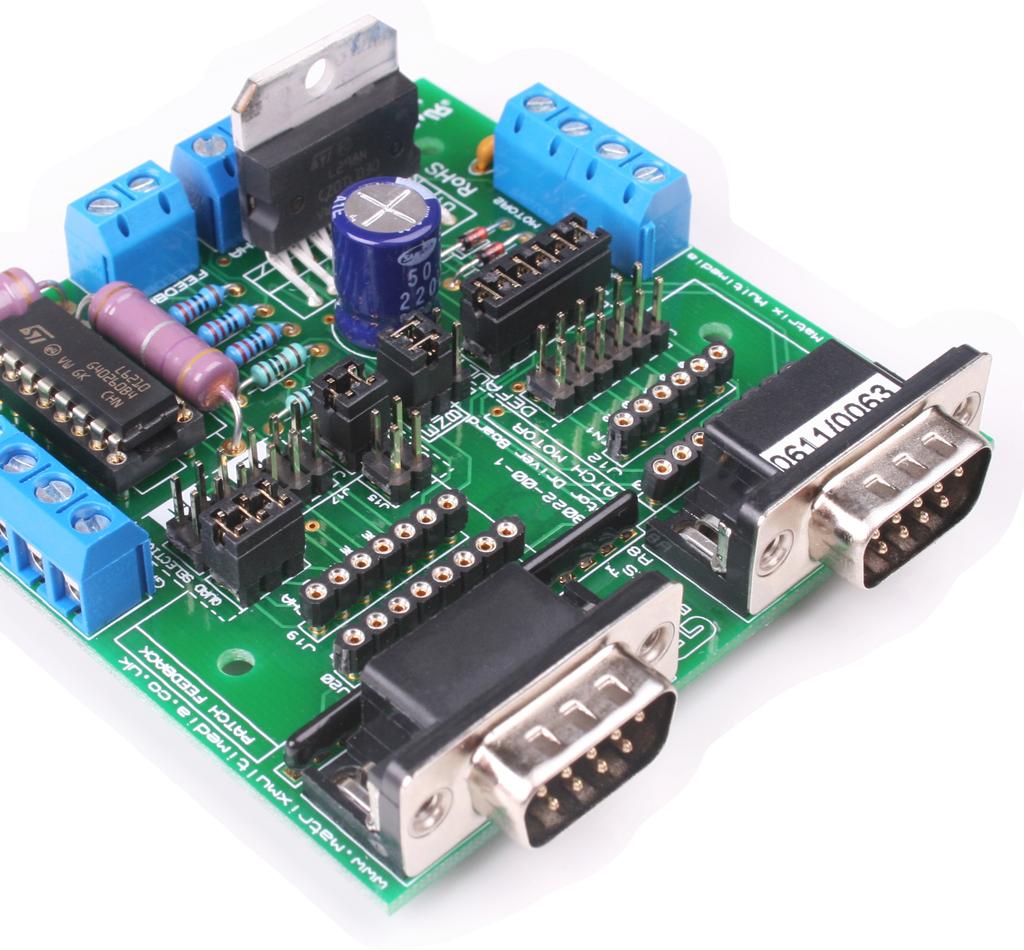


1 Motor driver board EB022


2 Contents About this document 3 Board layout 3 General information 4 Circuit description 5 Circuit diagram 6 2 Copyright

3 About this document This document concerns the EB022 E-blocks motor driver board. 1. Trademarks and copyright PIC and PICmicro are registered trademarks of Arizona Microchip Inc. E-blocks is a trademark of Matrix Multimedia Ltd. 2. Disclaimer The information provided within this document is correct at the time of going to press. Matrix Multimedia reserves the right to change specifications from time to time. 3. Testing this product It is advisable to test the product upon receiving it to ensure it works correctly. Matrix provides test procedures for all E-blocks, which can be found in the Support section of the website. 4. Product support If you require support for this product then please visit the Matrix website, which contains many learning resources for the E-blocks series. On our website you will find: How to get started with E-blocks - if you are new to E-blocks and wish to learn how to use them from the beginning there are resources available to help. Relevant software and hardware that allow you to use your E-blocks product better. Example files and programs. Ways to get technical support for your product, either via the forums or by contacting us directly. Board layout way downstream D-type connector 2. Motor patch system 3. Motor default selection pin 4. Motor 1 and motor 2 screw terminals 5. L298 dual full bridge driver 6. Quadrature encoder screw terminals 7. Feedback screw terminals 3 Copyright 8. Enable A / enable B selection jumper pin 9. Sense default selection jumper pin 10. L6210 monolithic IC 11. Feedback patch system 12. Power supply screw terminals 13. VPWR screw terminals

4 General information The motor driver board allows the user to connect and drive two motors independently of each other. The inclusion of sense and quadrature terminals permits the user to employ feedback and positional control of the motor. EB022 connectors Settings Motor jumper (J1) Default Enable (J13) Refer to the first circuit diagram (page 6), enable jumper system, diagram 3 Quad A or B Sense (J14) Default NB. Ensure jumper links are positioned vertically on ENA, ENB (J13) All other jumper links are to be positioned horizontally. NB. Ensure jumper links are positioned vertically on ENA, ENB (J13) All other jumper links are to be positioned horizontally. Motor patch system The motor patch system consists of one header pin connector (J10), an eight way SIL socket (J11) and a seven way SIL socket (J12). Selecting the patch default connector (J10) permits the user to connect IN1, IN2, IN3, IN4, ENA and ENB to any of the eight connections of the D type connector. Feedback patch system The feedback patch system consists of a header pin connector (J18), an eight way SIL socket (J20) and a seven way SIL socket (J19). Selecting the quad patch (J18) allows the user to transmit CA, CHB and CHI signals to any of the eight connections of the feedback D type connector. The sense patch (J15) can be used to transmit SENSE signals to any of the eight connections of the feedback D -type connector. 1. Features Provides the capacity to drive two motors simultaneously Provides independent PWM control of each motor Provides quadrature encoder capabilities to allow the user to sense both the position and direction of motor rotation 4 Copyright


5 Circuit description The EB018 motor driver circuit can be observed on page 6. This E-block allows the simultaneous control of two independent motors using a L298 Dual Full Bridge Driver, U1. The L298 takes input logic at 3.3V or higher from an upstream E-block via J2, and provides current and voltage gain to condition the signals for driving inductive loads such as DC and stepper motors. The combination of J1 and J2 link selection blocks allow users to use the default connections (please refer to the circuit diagram) or to define their own connections to the upstream E-blocks using jumper wires. The L298 can operate at voltages up to 46V 2A peak. Care must be taken not to exceed these ratings or the L298 may be damaged. Two enable inputs are provided to enable or disable the L298 independently of the other input signals. J13 can be wired in one of three ways: With the jumper block connectors lined up vertically, and on the top 4 connectors the enable lines are permanently connected to Vcc - always enabling the L298. With the jumper block in a horizontal position on the lower four connectors then the L298 takes its enable status from the inputs on J2. The outputs of the L298 are connected to the L6210 which contains eight Schottky diodes arranged as two separate diode bridges. The L6210 contains a number of diodes which clamp any induced reverse voltages from inductive loads to the ground and power rails to prevent damage to the circuit. The terminals J4 and J5 provide terminals for motor 1 and motor 2 respectively. Please refer to the second page of the circuit diagram: The resistors R1 and R2 are connected between the motor load and ground via the L298. The voltage across R1 and R2 is proportional to any current flowing through the motor and can therefore be used to sense the motor load or work rate. The two zener diodes clamp the resulting voltage to 3.3V to prevent high voltages being passed back to the upstream board. The screw terminal connector J21 allows quadrature feedback to be passed back to the controlling circuit via a patch and link block system. The screw terminal j& allows an additional input signal to be incorporated into your system. Resistors R7 and R8 provide protection for the upstream device. 3.3V operation This board is compatible with upstream boards operating off 3.3V. 5 Copyright

6 Circuit diagram 6 Copyright
LED board. EB004
 LED board www.matrixmultimedia.com EB004 Contents About this document 3 Board layout 3 General information 4 Circuit description 4 Protective cover 4 Circuit diagram 5 2 Copyright About this document This
Opto-isolator board. EB035
 Opto-isolator board www.matrixtsl.com EB035 Contents About this document Board layout General information Circuit description Protective cover Circuit diagram 2 3 3 4 4 5 5 Copyright Matrix Technology
Power board. EB011
 Power board www.matrixtsl.com EB011 Contents About this document Board layout General information Circuit description Protective cover Circuit diagram 2 3 3 5 5 6 Copyright Matrix Technology Solutions
Raspberry Pi board. EB080
 Raspberry Pi board www.matrixmultimedia.com EB080 Contents About this document 3 Board layout 3 General information 4 Circuit description 4 Circuit diagram 5 2 Copyright Matrix Multimedia Ltd. About this
PS/2 and SVGA board. EB033
 PS/ and SVGA board www.matrixtsl.com EB033 Contents About this document 3 Board layout 3 General information 4 Circuit description 4 Circuit diagram 6 Copyright About this document This document concerns
Sensor board. EB003
 Sensor board www.matrixtsl.com EB003 Contents About this document 3 Board layout 3 General information 4 Circuit description 4 Protective cover 5 Circuit diagram 6 2 Copyright About this document This
Opto-isolator board datasheet EB
 Opto-isolator board datasheet EB-035-00-1 CONTENTS 1. About this document 2 2. General Information 3 3. Board layout. 4 4. Testing this product... 4 5. Circuit description. 5 Appendix 1 Circuit diagram
ECIO base board. EB061
 ECIO base board www.matrixmultimedia.com EB061 Contents About this document 3 Board layout 3 General information 4 Circuit description 4 Circuit diagram 5 2 Copyright Matrix Multimedia Ltd. About this
TFT Graphical LCD Board
 TFT Graphical LCD Board www.matrixtsl.com EB084 Contents About This Document 2 General Information 3 Board Layout 4 Testing This Product 5 Circuit Description 6 Circuit Diagram EB084 7 Circuit Diagram
RS485 board datasheet EB062-00
 RS485 board datasheet EB062-00 00-1 Contents 1. About this document... 2 2. General information... 3 3. Board layout... 4 4. Testing this product... 5 5. Circuit description... 6 Appendix 1 Circuit diagram
Wireless LAN board. EB069
 Wireless LAN board www.matrixmultimedia.com EB069 Contents About this document 3 Board layout 3 General information 4 Circuit description 4 Protective cover 5 Circuit diagram 6 2 Copyright Matrix Multimedia
Accelerometer board. EB068
 Accelerometer board www.matrixtsl.com EB0 Contents About this document Board layout General information Testing this product Circuit description 5 Circuit diagram Copyright 0 Matrix TSL About this document
Motor angle (servo) trainer board
 trainer board") Motor angle (servo) trainer board www.matrixtsl.com EB097 Contents About this document Board layout General information Protective cover Circuit description Circuit diagram 2 3 3 5 Copyright Matrix Technology
Motor angle (servo) trainer board www.matrixtsl.com EB097 Contents About this document Board layout General information Protective cover Circuit description Circuit diagram 2 3 3 5 Copyright Matrix Technology
OLED graphical LCD board
 OLED graphical LCD board www.matrixtsl.com EB057 EB058 Contents About this document Board layout General information Circuit description Protective cover Circuit diagram 2 4 4 5 6 Copyright Matrix Technology
LCD board. EB005
 LCD board www.matrixtsl.com EB005 Contents About this document 3 Board layout 3 General information 4 Circuit description 6 Protective cover 6 Circuit diagram 7 2 Copyright About this document This document
Graphical LCD Display Datasheet EB
 Graphical LCD Display Datasheet EB043-00-1 Contents 1. About this document... 2 2. General information... 3 3. Board layout... 6 4. Testing this product... 7 5. Circuit description... 8 Appendix 1 Circuit
ECIO Base Board datasheet EB061-00
 ECIO Base Board datasheet EB061-00 00-2 Contents 1. About this document... 2 2. General information... 3 3. Board layout... 4 4. Circuit description... 5 Appendix 1 Circuit diagram Copyright Matrix Multimedia
Home Automation Board datasheet
 Home Automation Board datasheet Contents 1. About this document 2. General information 3. Board Layout 4. Getting Started 5. Circuit Description Appendix 1 Circuit Diagram Copyright 2004 Matrix Multimedia
LIN bus board datasheet EB
 LIN bus board datasheet EB027-00-1 Contents 1. About this document... 2 2. General information... 3 3. Board layout... 4 4. Testing this product... 5 5. Circuit description... 7 Appendix 1 Circuit diagram
USB232 board. EB039
 USB232 board www.matrixtsl.com EB039 Contents About this document 3 Board layout 3 General information 4 Circuit description 4 Protective cover 5 Circuit diagram 6 2 Copyright About this document This
VGA multimedia board
 VGA multimedia board www.matrixtsl.com EB071 Contents About this document 3 Board layout 3 General information 4 Circuit description 5 Protective cover 5 Circuit diagram 6 2 Copyright About this document
Card Reader Board EB037-00
 Card Reader Board EB037-00 00-1 Contents 1. About this document... 2 2. General information... 3 3. Board layout... 4 4. Testing this product... 5 5. Circuit description... 6 Appendix 1 Circuit diagram
TFT LCD multimedia board with touchscreen
 TFT LCD multimedia board with touchscreen www.matrixtsl.com EB076-LCD32T Contents About this document 3 Board layout 3 General information 4 Circuit description 5 Circuit diagram 6 2 Copyright About this
eblocks A Adaptor Board datasheet Matrix Multimedia Adaptor Board Contents
 Adaptor Board datasheet version 2 board adaptor D E eblocks A C B Contents 1. About this document 2. General information 3. Board Layout 4. Getting Started 5. Circuit description Appendix o Circuit Diagram
IrDA Board datasheet. Matrix Multimedia IrDA Board. Contents
 IrDA Board datasheet Contents 1. About this document 2. General information 3. Board Layout 4. Getting Started 5. Circuit Description Appendix 1 Circuit Diagram Copyright 2004 Matrix Multimedia Limited
Internet board datasheet EB
 Internet board datasheet EB023-00-1 Contents 1. About this document... 2 2. General information... 3 3. Board layout... 4 4. Testing this product... 5 5. Circuit description... 9 Appendix 1 Circuit diagram
Bluetooth board EB Technical datasheet
 Bluetooth board EB024-00-2 Technical datasheet Contents 1. About this document... 2 2. General information... 3 3. Board layout... 4 4. Testing this product... 5 5. Circuit description... 7 Appendix 1
Wireless LAN board. EB069
 Wireless LAN board www.matrixmultimedia.com EB069 Contents About this document 3 Board layout 3 General information 4 Protective cover 4 Testing the product 5 Circuit description 6 Circuit diagram 7 2
CPLD board. EB020
 CPLD board www.matrixtsl.com EB020 Contents About this document Board layout General information Circuit description Protective cover Circuit diagram 2 4 5 7 Copyright About this document This document
1. About this document General information Board layout Testing this product Circuit description...
 dspic / PIC24 Multiprogrammer datasheet EB064-00 00-1 Contents 1. About this document... 2 2. General information... 3 3. Board layout... 4 4. Testing this product... 5 5. Circuit description... 6 Appendix
SPI memory and D/A board
 SPI memory and D/A board www.matrixtsl.com EB013 Contents About this document 3 Board layout 3 General information 4 Circuit description 4 Protective cover 6 Circuit diagram 7 2 Copyright About this document
USB232 board EB Technical datasheet
 USB232 board EB039-00-1 Technical datasheet Contents 1. About this document...2 2. General information...3 3. Board layout...4 4. Testing this product...5 5. Circuit description...7 Appendix 1 Circuit
SPI Memory and D/A board datasheet EB
 SPI Memory and D/A board datasheet EB013-00-2 Contents 1. About this document...2 2. General information...3 3. Board layout...4 4. Testing this product...5 5. Circuit description...6 Appendix 1 Circuit
4D Picaso Touchscreen Display board datasheet EB
 4D Picaso Touchscreen Display board datasheet EB076-00 00-1 CONTENTS 1. About this document. 2 2. General Information.. 3 3. Board layout... 3 4. Testing this product... 4 5. Circuit description.. 4 Appendix
CPLD board datasheet EB
 CPLD board datasheet EB020-00-3 Contents. About this document... 2 2. General information... 3 3. Board layout... 4 4. Testing this product... 5 5. Circuit description... 6 Appendix Circuit diagram Copyright
4X4 Driver Shield Manual
 3/31/2012 4X4 Driver Shield Manual High current, high side switching for Arduino Logos Electromechanical 4X4 Driver Shield Manual High current, high side switching for Arduino Introduction The Logos Electromechanical
CPLD board datasheet EB
 CPLD board datasheet EB020-00- Contents. About this document... 2 2. General information... 3 3. Board layout... 4 4. Testing this product... 5 5. Circuit description... 6 Appendix Circuit diagram Copyright
IR/IrDA transceiver board
 IR/IrDA transceiver board www.matrixtsl.com EB01 Contents About this document 3 Board layout 3 General information 4 Circuit description 5 Protective cover 7 Circuit diagram 8 Copyright About this document
ARM programmer and daughter board
 ARM programmer and daughter board www.matrixtsl.com EB185 Contents About this document 3 Board layout 3 General information 4 Circuit description 4 Protective cover 5 Circuit diagram 6 2 Copyright About
Pmod modules are powered by the host via the interface s power and ground pins.
 1300 Henley Court Pullman, WA 99163 509.334.6306 www.store. digilent.com Digilent Pmod Interface Specification 1.2.0 Revised October 5, 2017 1 Introduction The Digilent Pmod interface is used to connect
Dwarf Boards. DB021 : L298 dual motor driver
 Dwarf Boards DB021 : L298 dual motor driver (c) Van Ooijen Technische Informatica version 1.0 PICmicro, In-Circuit Serial Programming and ICSP are registerd trademarks of Microchip Technology Inc. Introduction
DMX512-4 Channel PWM Driver Board #805
 DMX512-4 Channel PWM Driver Board #805 Overview The 4-channel PWM driver board provides four open drain (collector) type outputs that can be directly controlled from a DMX512 network. The four channels
CDN503 HIGH DENSITY I/O ADAPTER USER GUIDE
 CDN503 HIGH DENSITY I/O ADAPTER USER GUIDE 13050301 (c) Copyright DIP Inc., 1996 DIP Inc. P.O. Box 9550 MORENO VALLEY, CA 92303 714-924-1730 CONTENTS DN503 PRODUCT OVERVIEW 1 DN503 INSTALLATION 1 POWER
Atmel AVR datasheet. Matrix Multimedia Atmel AVR Board EB Contents
 Atmel AVR datasheet Contents 1. About this document 2. General information 3. Board overview 4. Getting Started 5. Block schematic and description Appendix A. Circuit diagram B. Compatible AVR device C.
Sensor Board datasheet
 Sensor Board datasheet Contents 1. About this document 2. General information 3. Board Layout 4. Getting Started 5. Circuit description Appendix 1 Circuit Diagram 2 Sensors Copyright 2005 Matrix Multimedia
PICmicro Microcontroller Lite programmer datasheet
 PICmicro Microcontroller Lite programmer datasheet Contents 1. About this document 2. General information 3. Board overview 4. Getting Started 5. Block schematic and description Appendix A. Circuit diagram
ARM programmer and daughter board EB Technical datasheet
 ARM programmer and daughter board EB185-00-1 Technical datasheet Contents 1 About this document...2 2 General information...3 3 Description...3 4 Board layout...4 5 Testing this product...5 6 Circuit description...7
MODEL DRIVER Ic Ip VDC
 Provides Mounting & Connections for Stepnet Module CANopen Stepping Driver FEATURES Develop & Debug Stepnet projects then transfer design to OEM pc board. MODEL DRIVER Ic Ip VDC -075-01 STM-075-07 5 7
PICAXE EXPERIMENTER BOARD (AXE090)
") (AXE00) Description: The PICAXE experimenter board allows circuits for any size/revision of PICAXE chip ( / / ) to be quickly tested using a prototyping breadboard. The experimenter board provides power
(AXE00) Description: The PICAXE experimenter board allows circuits for any size/revision of PICAXE chip ( / / ) to be quickly tested using a prototyping breadboard. The experimenter board provides power
HUB-ee BMD-S Arduino Proto Shield V1.1
 HUB-ee BMD-S Arduino Proto Shield V1.1 User guide and assembly instructions Document Version 0.5 Introduction & Board Guide 2 Schematic 3 Quick User Guide 4 Assembly Guide 6 Kit Contents 7 1) Diodes and
MicrostepPLD Driver Manual Version 6/13/2006
 MicrostepPLD Driver Manual Version 6/13/2006 Embedded Acquisition Systems 2517 Cobden Street Sterling Heights, MI 48310 http://www.embeddedtronics.com email sales@embeddedtronics.com copyright 2003-2004
UNIVERSAL MOTION INTERFACE (UMI) ACCESSORY
 ACCESSORY") USER GUIDE UNIVERSAL MOTION INTERFACE (UMI) ACCESSORY Contents This user guide describes how to use the UMI-77, UMI-A, UMI-Flex, and UMI-Flex accessories. Introduction... What You Need to Get Started...
USER GUIDE UNIVERSAL MOTION INTERFACE (UMI) ACCESSORY Contents This user guide describes how to use the UMI-77, UMI-A, UMI-Flex, and UMI-Flex accessories. Introduction... What You Need to Get Started...
AVR Peripheral Board. Campus Component Pvt. Ltd.
 AVR Peripheral Board Campus Component Pvt. Ltd. DISCLAIMER Information furnished is believed to be accurate and reliable at the time of publication. However, Campus Component Pvt. Ltd. assumes no responsibility
unit : mm Parameter Symbol Conditions Ratings Unit
 Ordering number: EN3947B Monolithic Digital IC LB1836M Low-saturation, Bidirectional Motor Driver for Low-voltage Applications Overview The LB1836M is a low-saturation two-channel bidirectional motor driver
RoboClaw 2x30A Dual Channel Motor Controller
 RoboClaw 2x30A, 34VDC Dual Channel Brushed DC Motor Controller Version 2.2 (c) 2016 Ion Motion Control. All Rights Reserved. Feature Overview: 60 Amps Peak Per Channel Channel Bridging Supported Dual Quadrature
GUIDE TO SP STARTER SHIELD (V3.0)
") OVERVIEW: The SP Starter shield provides a complete learning platform for beginners and newbies. The board is equipped with loads of sensors and components like relays, user button, LED, IR Remote and
OVERVIEW: The SP Starter shield provides a complete learning platform for beginners and newbies. The board is equipped with loads of sensors and components like relays, user button, LED, IR Remote and
HDBB Breakout board user s manual
 HDBB Breakout board user s manual The HDBB breakout board was designed to use with our Whale2(-T)*, Whale3, Mammut* and Dugong servo drives or with any other third party stepper or servo drives which using
PP-BOB2-V1.0 PARALLEL PORT BREAKOUT BOARD
 PP-BOB2-v1 PARALLEL PORT BREAKOUT BOARD Document: Operation Manual Document #: T17 Document Rev: 2.0 Product: PP-BOB2-v1.0 Product Rev: 1.0 Created: March, 2013 Updated: Dec, 2014 THIS MANUAL CONTAINS
D115 The Fast Optimal Servo Amplifier For Brush, Brushless, Voice Coil Servo Motors
 D115 The Fast Optimal Servo Amplifier For Brush, Brushless, Voice Coil Servo Motors Ron Boe 5/15/2014 This user guide details the servo drives capabilities and physical interfaces. Users will be able to
HUB-ee BMD-S Arduino Proto Shield V1.0
 HUB-ee BMD-S Arduino Proto Shield V1.0 User guide and assembly instructions Document Version 1.0 Introduction 2 Schematic 3 Quick user guide 4 Assembly 5 1) DIP Switches 5 2) Micro-MaTch Connector Headers
KPIC-0818P (V050919) Devices Included in this Data sheet: KPIC-0818P
 Devices Included in this Data sheet: KPIC-0818P") Devices Included in this Data sheet: KPIC-0818P Features: Carefully designed prototyping area Accepts 8 pin PIC12 series micro-controllers Accepts 14 and 18 Pin PIC16 series Accepts some 8,14 and 18 pin
Devices Included in this Data sheet: KPIC-0818P Features: Carefully designed prototyping area Accepts 8 pin PIC12 series micro-controllers Accepts 14 and 18 Pin PIC16 series Accepts some 8,14 and 18 pin
RKP08 Component List and Instructions
 RKP08 Component List and Instructions PCB layout Constructed PCB RKP08 Scematic RKP08 Project PCB Page 1 Description The RKP08 project PCB has been designed to use PIC microcontrollers such as the Genie
UNIVERSAL MOTION INTERFACE (UMI) ACCESSORY
 ACCESSORY") USER GUIDE UNIVERSAL MOTION INTERFACE (UMI) ACCESSORY Introduction This user guide describes how to use the UMI-A, UMI-Flex, and UMI-Flex accessories. The UMI products are connectivity accessories you
USER GUIDE UNIVERSAL MOTION INTERFACE (UMI) ACCESSORY Introduction This user guide describes how to use the UMI-A, UMI-Flex, and UMI-Flex accessories. The UMI products are connectivity accessories you
MP6500 Stepper Motor Driver, Digital Current Control
 This breakout board for the MPS MP6500 micro stepping bipolar stepper motor driver is Pololu s latest stepper motor driver. The module has a pinout and interface that are very similar to that of our popular
Branch PLC. Velocio s Branch PLC
 Velocio s Branch PLC Branch PLC The Branch PLC is a member of the Velocio s groundbreaking series of programmable logic controllers. These PLCs introduce revolutionary new concepts, capabilities, performance
A4988 Stepper Motor Driver Carrier with Voltage Regulators
 1 of 6 12/2/2011 6:37 PM A4988 Stepper Motor Driver Carrier with Voltage Regulators Pololu item #: 1183 26 in stock Price break Unit price (US$) 1 19.95 10 17.95 100 13.97 Quantity: backorders allowed
Quick Start Guide. SEB-710 I/O Expansion board. Introduction
 SEB-710 I/O Expansion board Revision 1.0 - (March, 2011) Saflec Systems (Pty) Ltd Quick Start Guide Introduction The SEB-710 is an I/O expansion device for additional inputs and outputs. It has eight relay
8051 Intermidiate Development Board. Product Manual. Contents. 1) Overview 2) Features 3) Using the board 4) Troubleshooting and getting help
 Overview 2) Features 3) Using the board 4) Troubleshooting and getting help") 8051 Intermidiate Development Board Product Manual Contents 1) Overview 2) Features 3) Using the board 4) Troubleshooting and getting help 1. Overview 2. Features The board is built on a high quality FR-4(1.6
8051 Intermidiate Development Board Product Manual Contents 1) Overview 2) Features 3) Using the board 4) Troubleshooting and getting help 1. Overview 2. Features The board is built on a high quality FR-4(1.6
USB I/O-CARD WITH 32 INPUTS
 ORDERING NO. 4 016138 489224 Best. Nr. 502176 Control systems, switchgear cabinets Building automation, Home Automation Model construction, model railroads Step motor control and actuators I/O-card for
GammaRay USB Module. Beta Innovations DOC No. : Rev. : A2-102 Date : 2, 2004 Part No. : ,
 GammaRay USB Module DOC No. : 16410 Rev. : A2-102 Date : 2, 2004 Part No. : 500-101, 700-100 Beta Innovations (c) 2003 1 Table of Contents Table of Contents...2 GammaRay-64 USB Module...3 GammaRay-256
MIDI CPU Hardware Rev K. User Manual
 MIDI CPU Hardware Revision K User Manual Updated 2010-09-08 Additional documentation available at: http://highlyliquid.com/support/ Page 1 / 18 Table of Contents 1.0 Important Safety Information...2 2.0
Good Idea to Working Electronic Model
 Good Idea to Working Electronic Model by Jan H. Lichtenbelt, March 2011 Abstract Seeing an idea manifest itself into a fully working creation is always satisfying, however so many good ideas go to waste
PP-BOB2-V2.0 PARALLEL PORT BREAKOUT BOARD
 PP-BOB2-V2 PARALLEL PORT BREAKOUT BOARD Document: Operation Manual Document #: T18 Document Rev: 1.0 Product: PP-BOB2-V2.0 Product Rev: 1.0 Created: October, 2015 THIS MANUAL CONTAINS INFORMATION FOR INSTALLING
SRI-02 Speech Recognition Interface
 SRI-02 Speech Recognition Interface Data & Construction Booklet The Speech Recognition Interface SRI-02 allows one to use the SR-07 Speech Recognition Circuit to create speech controlled electrical devices.
User Manual. UIM240XX Series Parallel Signal Control Miniature Integrated Stepper Motor Driver
 User Manual UIM240XX Series Parallel Signal Control Miniature Integrated Stepper Motor Driver UIM24002/04/08 Please pay attention to the following before using the Mach Motion products: - Mach Motion products
Parameter Symbol Conditions Ratings Unit
 Ordering number : EN397F LB136M Monolithic Digital IC Low-Saturation Bidirectional Motor Driver for Low-Voltage Drive Overview The LB136M is a low-saturation two-channel bidirectional motor driver IC for
CV Arpeggiator Rev 2 Build Documentation.
 CV Arpeggiator Rev Build Documentation. Last updated 8-0-03 The CV Arpeggiator is a modular synth project used for creating arpeggios of control voltage. It utilizes a custom programmed PIC 6F685 micro
RoboClaw 120A/160A/200A Dual Channel Motor Controller
 RoboClaw 2x160A, 34VDC Dual Channel RoboClaw 2x120AHV, 60VDC Dual Channel RoboClaw 2x160AHV, 60VDC Dual Channel RoboClaw 2x200AHV, 60VDC Dual Channel Brushed DC Motor Controllers Version 2.1 (c) 2016 Ion
MSD325 Microstepping Drive
 MSD325 Microstepping Drive Introduction MSD325 is a very small size microstepping drive based on most advanced technology in the world today. It is suitable for driving any 2-phase and 4-phase hybrid stepper
PAC5523EVK1. Power Application Controllers. PAC5523EVK1 User s Guide. Copyright 2017 Active-Semi, Inc.
 PAC5523EVK1 Power Application Controllers PAC5523EVK1 User s Guide www.active-semi.com Copyright 2017 Active-Semi, Inc. CONTENTS Contents...2 Overview...3 PAC5523EVK1 Resources...5 Pinout and Signal Connectivity...5
GRAVITECH GROUP
 GRAVITECH.US uresearch GRAVITECH GROUP Description The I2C-ADC board is a 14-pin CMOS device that provides 8-CH, 12-bit of Analog to Digital Converter (ADC) using I 2 C bus. There are no external components
solutions for teaching and learning
 RKP18Motor Component List and Instructions PCB layout Constructed PCB Schematic Diagram RKP18Motor Project PCB Page 1 Description The RKP18Motor project PCB has been designed to use PIC microcontrollers
Stepper motor driver Tiny-Step II Last change:
 Documentation for Stepper motor driver Tiny-Step II Last change: 24.9.2011 Functional description Tiny-Step II is a one channel motor driver for 2-phase stepping motors with pulse and direction interface.
Galil Motion Control. DMC - 18x6. Datasheet (US ONLY)
") Galil Motion Control DMC - 18x6 Datasheet Galil Motion Control 270 Technology Way, Rocklin, CA 1-916-626-0101 (US ONLY) 1-800-377-6329 Product Description The DMC-18x6 PCI bus motor controllers belong
Galil Motion Control DMC - 18x6 Datasheet Galil Motion Control 270 Technology Way, Rocklin, CA 1-916-626-0101 (US ONLY) 1-800-377-6329 Product Description The DMC-18x6 PCI bus motor controllers belong
For pricing, delivery, and ordering information, please contact ISSI at or call
 IS3AP488D Class-AB Audio Amplifier Evaluation Board Guide Description The IS3AP488D demo board is a fully assembled and tested PCB that uses the IS3AP488D Class-AB a dual bridge-connected audio power amplifier.
InStep Plus Hardware Manual (Instep with Expansion Board) For Main board Rev 1 and Expansion board Rev 0
 For Main board Rev 1 and Expansion board Rev 0") Design, Application and Service of Electronics in Industry InStep Plus Hardware Manual (Instep with Expansion Board) For Main board Rev 1 and Expansion board Rev 0 (To be used in conjunction with the appropriate
Design, Application and Service of Electronics in Industry InStep Plus Hardware Manual (Instep with Expansion Board) For Main board Rev 1 and Expansion board Rev 0 (To be used in conjunction with the appropriate
Explorer V1.20. Features
 V1.20 Multi-function USB I/O Expander and Controller Features Dual h-bridge 1.3A motor drive with PWM speed control 4.6V to 10.8V input range USB communication 4x digital inputs 2x analogue inputs 7x 100mA
ADDJOG User Guide 7/30/10. Overview
 ADDJOG User Guide 7/30/10 Overview The ADDJOG is a PLC expansion board used to add digital inputs and outputs to a compatible host PLC. The ADDJOG has 64 open collector outputs and 64 non-isolated inputs.
Applications of 8051 Microcontrollers
 Applications of 8051 Microcontrollers INTRODUCTION: A microcontroller is a versatile chip which can be used in various fields starting from simple consumer electronics, measuring devices to high end medical,
Designing a NextMove PCI Breakout Unit
 Designing a NextMove PCI Breakout Unit MN1277BU Issue 1.0 MN1277BU 05/2000 . Copyright and Safety Information Copyright Baldor Optimised Control Ltd 2000. All rights reserved. This manual is copyrighted
User Manual. UIM240XX Series Parallel Signal Control Miniature Integrated Stepper Motor Driver
 User Manual UIM240XX Series Parallel Signal Control Miniature Integrated Stepper Motor Driver UIM24002/04/08 Please pay attention to the following before using the UIROBOT products: UIROBOT products meet
Universal Keying Adapter 3+
 Universal Keying Adapter 3+ The Universal Keying Adapter Version 3+ kit will allow you to key nearly any transmitter or transceiver with a straight key, electronic keyer, computer serial or parallel port
The SilverNugget is a servo controller/driver for NEMA 34 frame microstep motors.
 Date: 25 July 2008 www.quicksilvercontrols.com SilverNugget N3 M-Grade The SilverNugget is a servo controller/driver for NEMA 34 frame microstep motors. Property of Page 1 of 13 This document is subject
BSH-DRV-1 Bass Shaker Driver Data Sheet (V0.4) BFF Design Ltd
 BFF Design Ltd") BSH-DRV-1 Bass Shaker Driver Data Sheet (V0.4) BFF Design Ltd 1. Introduction The BFF BSH-DRV-1 card is a direct driver for bass shakers (vibration transducers). It provides vibration/rumble effects for
BSH-DRV-1 Bass Shaker Driver Data Sheet (V0.4) BFF Design Ltd 1. Introduction The BFF BSH-DRV-1 card is a direct driver for bass shakers (vibration transducers). It provides vibration/rumble effects for
User Manual. UIM240XX Series Parallel Signal Control Miniature Integrated Stepper Motor Driver V1.2
 User Manual UIM240XX Series Parallel Signal Control Miniature Integrated Stepper Motor Driver V1.2 UIM24002/04/08 Please pay attention to the following before using the UIROBOT products: UIROBOT products
ZLED7030KIT-D1 Demo Kit Description
 ZLED7030KIT-D Demo Kit Description Kit Important Notice Restrictions in Use IDT s ZLED7030KIT-D Demo Kit hardware is designed for ZLED7030 demonstration, evaluation, laboratory setup, and module development
MDK. Accelnet Module DevKit. Provides Mounting & Connections for Accelnet CANopen Servoamplifiers FEATURES
 Provides Mounting & Connections for Accelnet CANopen Servoamplifiers FEATURES Works with all Accelnet Models Develop & Debug Accelnet projects then transfer design to oem pc board. Dev Kit Model * Vdc
UCBB dual port breakout board user's manual
 UCBB dual port breakout board user's manual 1/14 Contents 1 Features 2 Dimensions 3 Connectors 3.1 Screw terminals 3.2 IDC ports 3.3 Powering 3.4 Outputs 3.5 Inputs 4 LED indicators 5 Example connections
INTRODUCTION. Mechanical Considerations APPLICATION NOTE Z86E21 THERMAL PRINTER CONTROLLER ZILOG
 ZILOG DESIGNING A LOW-COST THERMAL PRINTER USING THE Z86E21 TO CONTROL THE OPERATING CURRENT ON LOW-COST THERMAL PRINTERS PROVIDES DESIGN FLEXIBILITY AND HELPS SAFEGUARD PERFORMANCE. INTRODUCTION Compact
UMR2. User Manual. Hardware RevC Firmware V1.0. Updated Additional documentation and support available at:
 UMR2 User Manual Hardware RevC Firmware V1.0 Updated 2014-02-05 Additional documentation and support available at: http://forum.highlyliquid.com/ 2012 Sonarcana LLC Page 1 / 11 Table of Contents 1.0 Overview...3