EC 6504 MICROPROCESSOR AND MICROCONTROLLER Electronicsand Communication Engineering Fifth Semester UNIT-1I Part A 1. Definemachinecycle.
|
|
|
- Harry Rodgers
- 5 years ago
- Views:
Transcription
1 EC 6504 MICROPROCESSOR AND MICROCONTROLLER Electronicsand Communication Engineering Fifth Semester UNIT-1I Part A 1. Definemachinecycle. [N/D 16] Machine cycle is defined as the time required to complete the one operation of accessing memory, I/O or acknowledging an external request. This cycle may consist of three to six T-states. Four steps of Machine cycle 1. Fetch - Retrieve an instruction from the memory. 2. Decode - Translate the retrieved instruction into a series of computer commands. 3. Execute - Execute the computer commands. 4. Store - Send and write the results back in memory. 2. Under what conditions can bus contention occurs?how does a tri-state buffer help avoid this problem? [N/D 16] Bus contention occurs when two outputs attempting to control the same line. It can be avoided by tri-state buffer can be turned off 3. DifferentialExternalVerses InternalBus. [M/J-16] Internal Data Bus: As its name suggests the internal data bus only works inside a CPU that is internally. It is able to communicate with the internal cache memories of the CPU. Since they are internally placed they are relatively quick and are now affected by the rest of the computer. External Data bus: This type of bus is used to connect and interface the computer to its connected peripheral devices. Since they are external and do not lie within the circuitry of the CPU they are relatively slower. The 8088 processor in itself contains a 16-bit internal data bus coupled with a 20-bit address register. This allows the processor to address to a maximum of 1 MB memory. 4. Compareclosely coupledandloosely coupledconfigurations [M/J-16] Closely coupled Loosely coupled 1. Single CPU is used 1. Multiple CPU modules are used 2. It has local bus only 2. It has local as well system bus 3. No system memory or IO 3. It has system memory and IO, shared among CPU modules 4. No bus arbitration logic required 4. Bus arbitration logic required

2 5. What is the use of Instruction Queue in 8086 microprocessor? The queue operates on the principle of first in first out(fifo). So that the execution unit gets the instruction for execution in the order they fetched.feature of fetching the next instruction while the current instruction is executing is called pipelining which will reduce the execution time. 6. How many data lines and address lines are available in 8086? Address lines= 20 bit address bus Data lines= 16 bit data bus 7. What are the signals used in 8086 maximum mode operation? Qs1,Qs0, s0,s1, s2, LOCK, RQ/GT1, RQ/GT0 are the signals used in 8086 maximum mode operation. 8. List the advantages of using segment registers in It allows the memory addressing capacity to be 1MB even though the address associated with individual instruction is only 16-bit. It facilitates use of separate memory areas for program, data and stack. It allows the program to be relocated which is very useful in multiprogramming. 9.Explain the BHE and LOCK signals of 8086 BHE (Bus High Enable): Low on this pin during first part of the machine cycle indicates that at least one byte of the current transfer is to be made on higher byte AD15-AD8. LOCK: This signal indicates that an instruction with a LOCK prefix is being executed and the bus is not to be used by another processor. 10. Name any four flags of Auxiliary carry flag(af), Carry flag(cf), Direction flag(df), Interrupt flag(if), Overflow flag(of), Parity flag)pf), Sign flag(sf), Trap flag(tf), Zero flag(zf). Part B 1.Discussabout themultiprocessorconfigurations of8086. [16][N/D-16]
3
4
5
6
7 2. ExplainindetailabouttheMinimum mode and systembustimingof8086/8088 [16] [N/D-16] In a minimum mode 8086 system, the microprocessor 8086 is operated in minimum mode by strapping its MN/MX* pin to logic1. In this mode, all the control signals are given out by the microprocessor chip itself. There is a single microprocessor in the minimum mode system. The remaining components in the system are latches, transreceivers, clock generator, memory and I/O devices. Some type of chip selection logic may be required for selecting memory or I/O devices, depending upon the address map of the system. The latches are generally buffered output D-type flip-flops, like, 74LS373 or They are used for separating the valid address from the multiplexed address/data signals and are controlled by the ALE signal generated by Transreceivers are the bidirectional buffers and some times they are called as data amplifiers. They are requiredto separate the valid data from the time multiplexed address/data signal. They are controlled by two signals, namely, DEN* and DT/R*. The DEN* signal indicates that the valid data is available on the data bus, while DT/R indicates the direction of data, i.e. from or to the processor. The system contains memory for the monitor and users programstorage. Usually, EPROMS are used for monitor storage, while RAMs for users program storage. A system may contain I/O devices for communication with the processor as well as some special purpose I/O devices. The clock generator generates the clock from the crystal oscillator and then shapes it and divides to make it more precise so that it can be used as an accurate timing reference for the system. The clock generator also synchronizes some external signals with the system clock. The general system organization is shown in Fig Since it has 20 address lines and 16 data lines, the 8086 CPU requires three octal address latches and two octal data buffers for the complete address and data separation. The working of the minimum mode configuration system can be better described in terms of the timing diagrams rather than qualitatively describing the operations. The opcode fetch and read cycles are similar. Hence the timing diagram can be categorized in two parts, the first is the timing diagram for read cycle and the second is the timing diagram for write cycle. Fig 1.2 shows the read cycle timing diagram. The read cycle begins in T1 with the assertion of the address latch enable (ALE) signal and also M/IO* signal. During the negative going edge of this signal, the valid address is latched on the local bus. The BHE* and A0 signals address low, high or both bytes. From Tl to T4, the M/IO* signalindicates a memory or I/O operation. At T2 the address is removed from the local bus and is sent to the output. The bus is then tristated. The read (RD*) control signal is also activated in T2.The read (RD) signal causes the addressed device to enable its data bus drivers. After RD* goes low, the valid data is available on the data bus. The addresseddevice will drive the READY line high, when the processor returns the read signal to high level, the addressed device will again tristate its bus drivers.

.")
8 Fig 1.3 shows the write cycle timing diagram. A write cycle also begins with the assertion of ALE and the emission of the address. The M/IO* signal is again asserted to indicate a memory or I/O operation. In T2 after sending the address in Tl the processor sends the data to be written to the addressed location. The data remains on the bus untilmiddle of T4 state. The WR* becomes active at the beginning oft2 (unlike RD* is somewhat delayed in T2 to provide time for floating).the BHE* and A0 signals are used to select the proper byte or bytes of memory or I/O word to be read or written. The M/IO*, RD* and WR* signals indicate the types of data transfer as specified in Table


9 HOLD Response Sequence The HOLD pin is checked at the end of the each bus cycle. If it is received active by the processor before T4 of the previous cycle or during T1 state of the current cycle, the CPU activities HLDA in the next clock cycle and for the succeeding bus cycles, the bus will be given to another requesting master The control control of the bus is not regained by the processor until the requesting master does not drop the HOLD pin low. When the request is dropped by the requesting master, the HLDA is dropped by the processor at the trailing edge of the next clock as shown in fig 1.4.
![3. ExplainindetailabouttheMaximum mode and systembustimingof8086. [16] [M/J-16] In the maximum mode, the 8086 is operated by strapping the MN/MX* pin to ground.](/docs-images/89/98367968/images/10-0.jpg "In this mode, the processor derives the status signals S2*, S1* and S0*. Another chip called bus controller derives the control signals using this status information.")
10 3. ExplainindetailabouttheMaximum mode and systembustimingof8086. [16] [M/J-16] In the maximum mode, the 8086 is operated by strapping the MN/MX* pin to ground. In this mode, the processor derives the status signals S2*, S1* and S0*. Another chip called bus controller derives the control signals using this status information. In the maximum mode, there may be more than one microprocessor in the system configuration. The other components in the system are the same as in the minimum mode system. The general system organization is as shown in the fig1.1 The basic functions of the bus controller chip IC8288, is to derive control signals like RD* and WR* (for memory and I/O devices), DEN*, DT/R*, ALE, etc. using the information made available by the processor on the status lines. The bus controller chip has input lines S2*, S1* and S0* and CLK. These inputs to 8288 are driven by the CPU. It derives the outputs ALE, DEN*, DT/R*, MWTC*, AMWC*, IORC*, IOWC* and AIOWC*. The AEN*, IOB and CEN pins are especially useful for multiprocessor systems. AEN* and IOB are generally grounded. CEN pin is usually tied to +5V. Fig 1.1 Maximum Mode 8086 System


11 The significance of the MCE/PDEN* output depends upon the status of the IOB pin. If IOB is grounded, it acts as master cascade enable to control cascaded 8259A; else it acts as peripheral data enable used in the multiple bus configurations. INTA* pin is used to issue two interrupt acknowledge pulses to the interrupt controller or to an interrupting device. IORC*, IOWC* are I/O read command and I/O write command signals respectively. These signals enable an IO interface to read or write the data from or to the addressed port. The MRDC*, MWTC* are memory read command and memory write command signals respectively and may be used as memory read and write signals. All these command signals instruct the memory to accept or send data from or to the bus. For both of these write command signals, the advanced signals namely AIOWC* and AMWTC* are available. They also serve the same purpose, but are activated one clock cycle earlier than the IOWC* and MWTC* signals, respectively. The maximum mode system is shown in fig The maximum mode system timing diagrams are also divided in two portions as read (input) and write (output) timing diagrams. The address/data and address/status timings are similar to the minimum mode. ALE is asserted in T1, just like minimum mode. The only difference lies in the status signals used and the available control and advanced command signals. The fig. 1.2 shows the maximum mode timings for the read operation while the fig. 1.3 shows the same for the write operation. Fig1.4. RQ*/GT* Timings in Maximum Mode Fig. 1.2 Memory Read Timing in Maximum Mode
 MultiprocessorSystem (4) Multiprocessor means a multiple set of processors that executes instructions simultaneously.")
12 Timings for RQ*/GT* Fig. 1.3 Memory Write Timing in Maximum Mode 4. Explainthefollowing: [M/J-16] (i) MultiprocessorSystem (4) Multiprocessor means a multiple set of processors that executes instructions simultaneously. There are three basic multiprocessor configurations. Coprocessor configuration Closely coupled configuration Loosely coupled configuration How is the coprocessor and the processor connected? The coprocessor and the processor is connected via TEST, RQ-/GT- and QS0& QS1 signals. The TEST signal is connected to BUSY pin of coprocessor and the remaining 3 pins are connected to the coprocessor s 3 pins of the same name. TEST signal takes care of the coprocessor s activity, i.e. the coprocessor is busy or idle. The RT-/GT-is used for bus arbitration. The coprocessor uses QS0& QS1 to track the status of the queue of the host processor. Closely Coupled Configuration Closely coupled configuration is similar to the coprocessor configuration, i.e. both share the same memory, I/O system bus, control logic, and control generator with the host processor. However, the coprocessor and the host processor fetches and executes their own instructions. The system bus is controlled by the coprocessor and the host processor independently.
13 Block Diagram of Closely Coupled Configuration How is the processor and the independent processor connected? Communication between the host and the independent processor is done through memory space. None of the instructions are used for communication, like WAIT, ESC, etc. The host processor manages the memory and wakes up the independent processor by sending commands to one of its ports. Then the independent processor accesses the memory to execute the task. After completion of the task, it sends an acknowledgement to the host processor by using the status signal or an interrupt request. Loosely Coupled Configuration Block Diagram of Loosely Coupled Configuration
14 Loosely coupled configuration consists of the number of modules of the microprocessor based systems, which are connected through a common system bus. Each module consists of their own clock generator, memory, I/O devices and are connected through a local bus. Advantages Having more than one processor results in increased efficiency. Each of the processors have their own local bus to access the local memory/i/o devices. This makes it easy to achieve parallel processing. The system structure is flexible, i.e. the failure of one module doesn t affect the whole system failure; faulty module can be replaced later. (ii) Coprocessor (4) A Coprocessor is a specially designed circuit on microprocessor chip which can perform the same task very quickly, which the microprocessor performs. It reduces the work load of the main processor. The coprocessor shares the same memory, IO system, bus, control logic and clock generator. The coprocessor handles specialized tasks like mathematical calculations, graphical display on screen, etc. The 8086 and 8088 can perform most of the operations but their instruction set is not able to perform complex mathematical operations, so in these cases the microprocessor requires the math coprocessor like Intel 8087 math coprocessor, which can easily perform these operations very quickly. Block Diagram of Coprocessor Configuration (iii) Multiprogramming (4) Multiprogramming is a rudimentary form of parallel processing in which several programs are run at the same time on a uniprocessor. Since there is only one processor, there can be no true simultaneous execution of different programs. Instead, the operating system executes

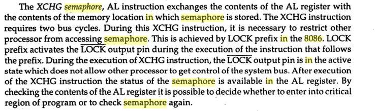
15 part of one program, then part of another, and so on. To the user it appears that all programs are executing at the same time. If the machine has the capability of causing an interrupt after a specified time interval, then the operating system will execute each program for a given length of time, regain control, and then execute another program for a given length of time, and so on. In the absence of this mechanism, the operating system has no choice but to begin to execute a program with the expectation, but not the certainty, that the program will eventually return control to the operating system. If the machine has the capability of protecting memory, then a bug in one program is less likely to interfere with the execution of other programs. In a system without memory protection, one program can change the contents of storage assigned to other programs or even the storage assigned to the operating system. The resulting system crashes are not only disruptive, they may be very difficult to debug since it may not be obvious which of several programs is at fault. (iv) Semaphore (4)
16
EC 6504 Microprocessor and Microcontroller. Unit II System Bus Structure
 EC 6504 Microprocessor and Microcontroller Unit II 8086 System Bus Structure Syllabus: 8086 Signals Basic Configurations System bus timing System Design using 8086 IO Programming Introduction to multiprogramming
UNIT II OVERVIEW MICROPROCESSORS AND MICROCONTROLLERS MATERIAL. Introduction to 8086 microprocessors. Architecture of 8086 processors
 OVERVIEW UNIT II Introduction to 8086 microprocessors Architecture of 8086 processors Register Organization of 8086 Memory Segmentation of 8086 Pin Diagram of 8086 Timing Diagrams for 8086 Interrupts of
MICROPROCESSOR TECHNOLOGY
 MICROPROCESSOR TECHNOLOGY Assis. Prof. Hossam El-Din Moustafa Lecture 12 Ch.5 8086/8088 Hardware Specifications 22-Mar-15 1 The Buffered System If more than 10 unit loads are attached to any bus pin, the
UNIT-1. It is a 16-bit Microprocessor (μp).it s ALU, internal registers works with 16bit binary word.
.it s ALU, internal registers works with 16bit binary word.") UNIT-1 Introduction to 8086: 8086 Microprocessor is an enhanced version of 8085Microprocessor that was designed by Intel in 1976. It is a 16-bit Microprocessor having 20 address lines and16 data lines
UNIT-1 Introduction to 8086: 8086 Microprocessor is an enhanced version of 8085Microprocessor that was designed by Intel in 1976. It is a 16-bit Microprocessor having 20 address lines and16 data lines
SRI VIDYA COLLEGE OF ENGINEERING AND TECHNOLOGY,VIRUDHUNAGAR
 Year/sem: 02/04 Academic Year: 2014-2015 (even) UNIT II THE 8086 SYSTEM BUS STRUCTURE PART A 1. What are the three groups of signals in 8086? The 8086 signals are categorized in three groups. They are:
UMBC. 80C86/80C88: CMOS version draws 10mA with temp spec -40 to 225degF. 450mV while input max can be no higher than 800mV). 0 0.
. 0 0.") 8086/88 Device Specifications Both are packaged in DIP (Dual In-Line Packages). 8086: 16-bit microprocessor with a 16-bit data bus 8088: 16-bit microprocessor with an 8-bit data bus. Both are 5V parts:
8086/88 Device Specifications Both are packaged in DIP (Dual In-Line Packages). 8086: 16-bit microprocessor with a 16-bit data bus 8088: 16-bit microprocessor with an 8-bit data bus. Both are 5V parts:
Pin diagram Common SignalS Architecture: Sub: 8086 HARDWARE
 1 CHAPTER 6 HARDWARE ARCHITECTURE OF 8086 8086 Architecture: 6.1 8086 Pin diagram 8086 is a 40 pin DIP using CHMOS technology. It has 2 GND s as circuit complexity demands a large amount of current flowing
8086 Hardware Specification
 Content: Segment 5 8086 Hardware Specification 8086 Modes of operation. Pin diagram and pin function of 8086. 8284A Clock generator operation and pin functions. Prepared By: Mohammed Abdul Kader Lecturer,
LECTURE NOTES MICROPROCESSORS AND INTERFACING DEVICES
 LECTURE NOTES ON MICROPROCESSORS AND INTERFACING DEVICES III B. Tech II semester (JNTUH-R15) Mr.R Mahendhar Reddy, Associate Professor, ECE ELECTRICAL AND ELECTRONICS ENGINEERING INSTITUTE OF AERONAUTICAL
PIN DIAGRAM. Richa Upadhyay Prabhu. NMIMS s MPSTME January 19, 2016
 PIN DIAGRAM Richa Upadhyay Prabhu NMIMS s MPSTME richa.upadhyay@nmims.edu January 19, 2016 Richa Upadhyay Prabhu (MPSTME) 8080 Microprocessor January 19, 2016 1 / 51 Pin Diagram of 8086 Richa Upadhyay
Overview of Intel 80x86 µp
 CE444 ١ ٢ 8088/808 µp and Supporting Chips Overview of Intel 80x8 µp ٢ ١ 8088/808 µp ٣ Both are mostly the same with small differences. Both are of bit internal Data bus Both have 0 bit address bus Capable
Overview of Computer Architecture & Organization. Co Attained : CO1 Hours required : 07 Self study : 10 hrs
 Overview of Computer Architecture & Organization Co Attained : CO1 Hours required : 07 Self study : 10 hrs Syllabus 1. Introduction of Computer Organization and Architecture. 2. Basic organization of computer
8086 PIN Diagram Signals with common functions in both Modes: The following signal description is common for both the minimum and maximum modes.
 UNIT II - 8086 SYSTEM BUS STRUCTURE 8086 signals Basic configurations System bus timing System design using 8086 IO programming Introduction to Multiprogramming System Bus Structure Multiprocessor configurations
UNIT-I. 1.Draw and explain the Architecture of a 8085 Microprocessor?
 UNIT-I INTRODUCTION TO MICROPROCESSOR A common way of categorizing microprocessors is by the no. of bits that their ALU can work with at a time. (i) The first commercially available microprocessor was
8088,80286 MICROPROCESSORS AND ISA BUS
 8088,80286 MICROPROCESSORS AND ISA BUS OBJECTIVES this chapter enables the student to: State the function of the pins of the 8088. List the functions of the 8088 data, address, and control buses. State
History of the Computers. Types of a computers, microcontrollers, microprocessors. Difference between microprocessors, microcontrollers &
 History of the Computers. Types of a computers, microcontrollers, microprocessors. Difference between microprocessors, microcontrollers & DigitalSignalProcessors. Introduction to 8 bit Microprocessors
 UNIT II SYSTEM BUS STRUCTURE 1. Differentiate between minimum and maximum mode 2. Give any four pin definitions for the minimum mode. 3. What are the pins that are used to indicate the type of transfer
1 MALP ( ) Unit-1. (1) Draw and explain the internal architecture of 8085.
 Unit-1. (1) Draw and explain the internal architecture of 8085.") (1) Draw and explain the internal architecture of 8085. The architecture of 8085 Microprocessor is shown in figure given below. The internal architecture of 8085 includes following section ALU-Arithmetic
(1) Draw and explain the internal architecture of 8085. The architecture of 8085 Microprocessor is shown in figure given below. The internal architecture of 8085 includes following section ALU-Arithmetic
Handout 15. by Dr Sheikh Sharif Iqbal. Memory Interface of 8088 and 8086 processors
 Handout 15 Ref: Online course on EE-390, KFUPM Objective: by Dr Sheikh Sharif Iqbal Memory Interface of 8088 and 8086 processors - To introduce the read and write bus cycles of the 8088 and 8086 processors.
Topic 2 :16 Bit Microprocessor: 8086 (24 Marks)
") Topic 2 :16 Bit Microprocessor: 8086 (24 Marks) Features of 8086 8086 is a 16 bit processor. It s ALU, internal registers works with 16bit binary word 8086 has a 16bit data bus. It can read or write data
Topic 2 :16 Bit Microprocessor: 8086 (24 Marks) Features of 8086 8086 is a 16 bit processor. It s ALU, internal registers works with 16bit binary word 8086 has a 16bit data bus. It can read or write data
MICROPROCESSOR QUESTION BANK. Unit 1
 QUESTION BANK Unit 1 1. Explain the term Microprocessor. ( CO1-K2) A microprocessor is a multipurpose, programmable logic device that receives binary instructions from a storage device called memory accepts
Architecture of 8085 microprocessor
 Architecture of 8085 microprocessor 8085 consists of various units and each unit performs its own functions. The various units of a microprocessor are listed below Accumulator Arithmetic and logic Unit
UNIT 1. Introduction to microprocessor. Block diagram of simple computer or microcomputer.
 UNIT 1 Unit 1 contents at a glance: 1. Architecture of 8086 microprocessor, 2. Register organization, 3. 8086 flag register and its functions, 4. addressing modes of 8086, 5. Pin diagram of 8086, 6. Minimum
1. Internal Architecture of 8085 Microprocessor
 1. Internal Architecture of 8085 Microprocessor Control Unit Generates signals within up to carry out the instruction, which has been decoded. In reality causes certain connections between blocks of the
Micro Processors & Micro Controllers Lecture Notes
 Micro Processors & Micro Controllers Lecture Notes (As Per JNTUK-[R07] Syllabus) Prepared By, Umasankar.Ch M.Tech(EC) ( -mail: sankarch.4u@gmail.com) Ch.Uma SankarM.Tech Page 2 Chapter CONTENTS Name of
ELE 3230 Microprocessors and Computer Systems
 ELE 3230 Microprocessors and Computer Systems Chapter 4 8088 System Architecture (*Hall:ch2; Brey:ch1; Triebel:ch2) ELE 3230 - Chapter 4 1 Historical Background 1969/70 Intel 4004, first Microprocessor
Microprocessor Architecture
 Microprocessor - 8085 Architecture 8085 is pronounced as "eighty-eighty-five" microprocessor. It is an 8-bit microprocessor designed by Intel in 1977 using NMOS technology. It has the following configuration
1. INTRODUCTION TO MICROPROCESSOR AND MICROCOMPUTER ARCHITECTURE:
 1. INTRODUCTION TO MICROPROCESSOR AND MICROCOMPUTER ARCHITECTURE: A microprocessor is a programmable electronics chip that has computing and decision making capabilities similar to central processing unit
2. List the five interrupt pins available in INTR, TRAP, RST 7.5, RST 6.5, RST 5.5.
 DHANALAKSHMI COLLEGE OF ENGINEERING DEPARTMENT OF ELECTRICAL AND ELECTRONICS ENGINEERING EE6502- MICROPROCESSORS AND MICROCONTROLLERS UNIT I: 8085 PROCESSOR PART A 1. What is the need for ALE signal in
MICROPROCESSOR TECHNOLOGY
 MICROPROCESSOR TECHNOLOGY Assis. Prof. Hossam El-Din Moustafa Lecture 13 Ch.6 The 80186, 80188, and 80286 Microprocessors 21-Apr-15 1 Chapter Objectives Describe the hardware and software enhancements
Pin Description, Status & Control Signals of 8085 Microprocessor
 Pin Description, Status & Control Signals of 8085 Microprocessor 1 Intel 8085 CPU Block Diagram 2 The 8085 Block Diagram Registers hold temporary data. Instruction register (IR) holds the currently executing
9/25/ Software & Hardware Architecture
 8086 Software & Hardware Architecture 1 INTRODUCTION It is a multipurpose programmable clock drive register based integrated electronic device, that reads binary instructions from a storage device called
Chapter NINE 8088,80286 MICROPROCESSORS AND ISA BUS
 Chapter NINE 8088,80286 MICROPROCESSORS AND ISA BUS OBJECTIVES this chapter enables the student to: State the function of the pins of the 8088. List the functions of the 8088 data, address, and control
Chapter 1: Basics of Microprocessor [08 M]
![Chapter 1: Basics of Microprocessor [08 M]](/thumbs/77/75860546.jpg "Chapter 1: Basics of Microprocessor [08 M]") Microprocessor: Chapter 1: Basics of Microprocessor [08 M] It is a semiconductor device consisting of electronic logic circuits manufactured by using either a Large scale (LSI) or Very Large Scale (VLSI)
Microprocessor: Chapter 1: Basics of Microprocessor [08 M] It is a semiconductor device consisting of electronic logic circuits manufactured by using either a Large scale (LSI) or Very Large Scale (VLSI)
QUESTION BANK. EE 6502 / Microprocessor and Microcontroller. Unit I Processor. PART-A (2-Marks)
") QUESTION BANK EE 6502 / Microprocessor and Microcontroller Unit I- 8085 Processor PART-A (2-Marks) YEAR/SEM : III/V 1. What is meant by Level triggered interrupt? Which are the interrupts in 8085 level
QUESTION BANK EE 6502 / Microprocessor and Microcontroller Unit I- 8085 Processor PART-A (2-Marks) YEAR/SEM : III/V 1. What is meant by Level triggered interrupt? Which are the interrupts in 8085 level
Microcomputer System Design
 Microcomputer System Design COE305 Lab. What is a Microprocessor? A microprocessor is a multipurpose, clockdriven, register-based electronic device that reads binary instructions from a storage device
Chapter 4 : Microprocessor System
 Chapter-4 Microprocessor System A microcomputer consists of a set of components or modules of three basic types CPU memory and I/O units which communicate with each other. PIN Configuration of 8085 Fig
MICROPROCESSOR MICROPROCESSOR. From the above description, we can draw the following block diagram to represent a microprocessor based system: Output
 8085 SATISH CHANDRA What is a Microprocessor? The word comes from the combination micro and processor. Processor means a device that processes whatever. In this context, processor means a device that processes
MICROPROCESSOR AND MICROCONTROLLER BASED SYSTEMS
 MICROPROCESSOR AND MICROCONTROLLER BASED SYSTEMS UNIT I INTRODUCTION TO 8085 8085 Microprocessor - Architecture and its operation, Concept of instruction execution and timing diagrams, fundamentals of
The Purpose of Interrupt
 Interrupts 3 Introduction In this chapter, the coverage of basic I/O and programmable peripheral interfaces is expanded by examining a technique called interrupt-processed I/O. An interrupt is a hardware-initiated
Control Unit: The control unit provides the necessary timing and control Microprocessor resembles a CPU exactly.
 Unit I 8085 and 8086 PROCESSOR Introduction to microprocessor A microprocessor is a clock-driven semiconductor device consisting of electronic logic circuits manufactured by using either a large-scale
In this tutorial, we will discuss the architecture, pin diagram and other key concepts of microprocessors.
 About the Tutorial A microprocessor is a controlling unit of a micro-computer, fabricated on a small chip capable of performing Arithmetic Logical Unit (ALU) operations and communicating with the other
CHAPTER 5 : Introduction to Intel 8085 Microprocessor Hardware BENG 2223 MICROPROCESSOR TECHNOLOGY
 CHAPTER 5 : Introduction to Intel 8085 Hardware BENG 2223 MICROPROCESSOR TECHNOLOGY The 8085A(commonly known as the 8085) : Was first introduced in March 1976 is an 8-bit microprocessor with 16-bit address
Basics of Microprocessor
 Unit 1 Basics of Microprocessor 1. Microprocessor Microprocessor is a multipurpose programmable integrated device that has computing and decision making capability. This semiconductor IC is manufactured
History and Basic Processor Architecture
 History and Basic Processor Architecture History of Computers Module 1 Section 1 What Is a Computer? An electronic machine, operating under the control of instructions stored in its own memory, that can
EC Microprocessor and Microcontroller
 DMI COLLEGE OF ENGINEERING EC6504 - Microprocessor and Microcontroller UNIT I THE 8086 MICROPROCESSOR 1. What are different data transfer schemes? The different data transfer schemes are [A/M 12] 2. How
Chapter 13 Direct Memory Access and DMA-Controlled I/O
 Chapter 13 Direct Memory Access and DMA-Controlled I/O The DMA I/O technique provides direct access to the memory while the microprocessor is temporarily disabled This allows data to be transferred between
8/26/2010. Introduction to 8085 BLOCK DIAGRAM OF INTEL Introduction to Introduction to Three Units of 8085
 BLOCK DIAGRAM OF INTEL 8085 GURSHARAN SINGH TATLA Introduction to 8085 It was introduced in 1977. It is 8-bit microprocessor. Its actual name is 8085 A. It is single NMOS device. It contains 6200 transistors
WINTER 12 EXAMINATION Subject Code : Model Answer Page No : / N. a) Describe the function of SID and SOD pins of 8085 microprocessor
 Describe the function of SID and SOD pins of 8085 microprocessor") Subject Code : Model Answer Page No : / N Q.1) SOLVE ANY FIVE : (20 MARKS) a) Describe the function of SID and SOD pins of 8085 microprocessor Ans: - SID: - (2 Mark) Serial Input Data SID pin is used to
Subject Code : Model Answer Page No : / N Q.1) SOLVE ANY FIVE : (20 MARKS) a) Describe the function of SID and SOD pins of 8085 microprocessor Ans: - SID: - (2 Mark) Serial Input Data SID pin is used to
Unit DMA CONTROLLER 8257
 DMA CONTROLLER 8257 In microprocessor based system, data transfer can be controlled by either software or hardware. To transfer data microprocessor has to do the following tasks: Fetch the instruction
12-Dec-11. Gursharan Singh Maninder Kaur. Introduction to 8085 BLOCK DIAGRAM OF INTEL Introduction to Introduction to 8085
 mailme@gursharansingh.in BLOCK DIAGRAM OF INTEL 8085 mailme@maninderkaur.in Introduction to 8085 It was introduced in 1977. It is 8-bit microprocessor. Its actual name is 8085 A. It is single NMOS device.
EC6504 MICROPROCESSOR AND MICROCONTROLLER
 UNIT I THE 8086 MICROPROCESSOR 1. What do you mean by Addressing modes? (May/June 2014) The different ways that a microprocessor can access data are referred to as addressing modes. 2. What is meant by
S.R.M. INSTITUTE OF SCIENCE & TECHNOLOGY SCHOOL OF ELECTRONICS & COMMUNICATION ENGINEERING
 S.R.M. INSTITUTE OF SCIENCE & TECHNOLOGY SCHOOL OF ELECTRONICS & COMMUNICATION ENGINEERING QUESTION BANK Subject Code : EC307 Subject Name : Microprocessor and Interfacing Year & Sem : III Year, V Sem
Design with Microprocessors
 Design with Microprocessors Year III Computer Science 1-st Semester Lecture 11: I/O transfer with x86 I/O Transfer I/O Instructions We discussed IN, OUT, INS and OUTS as instructions for the transfer of
Introduction to Microprocessor
 Introduction to Microprocessor The microprocessor is a general purpose programmable logic device. It is the brain of the computer and it performs all the computational tasks, calculations data processing
Unit I Introduction. Department of Electronics and Communication Engineering VARDHAMAN COLLEGE OF ENGINEERING Shamshabad, Hyderabad , India.
 Unit I Introduction Department of Electronics and Communication Engineering VARDHAMAN COLLEGE OF ENGINEERING Shamshabad, Hyderabad 501218, India. Pre-requisites Digital Logic Design (A1404) Computer Architecture
II/IV B.Tech (Regular/Supplementary) DEGREE EXAMINATION. Microprocessors and Microcontrollers. Answer ONE question from each unit.
 DEGREE EXAMINATION. Microprocessors and Microcontrollers. Answer ONE question from each unit.") Hall Ticket Number: 14 CS/IT 503 November, 2017 Fifth Semester Time: Three Hours Answer Question No.1 compulsorily. Answer ONE question from each unit. II/IV B.Tech (Regular/Supplementary) DEGREE EXAMINATION
Hall Ticket Number: 14 CS/IT 503 November, 2017 Fifth Semester Time: Three Hours Answer Question No.1 compulsorily. Answer ONE question from each unit. II/IV B.Tech (Regular/Supplementary) DEGREE EXAMINATION
 DHANALAKSHMI SRINIVASAN INSTITUTE OF RESEARCH AND TECHNOLOGY- SIRUVACHUR DEPARTMENT OF COMPUTER SCIENCE ENGINEERING EC6504-MICROPROCESSOR AND MICROCONTROLLER UNIT -I PART-A 1. Define microprocessor? A
Overview. M. Krishna Kumar MM/M4/LU10/V1/2004 1
 Overview Each processor in the 80x86 family has a corresponding coprocessor with which it is compatible Math Coprocessor is known as NPX,NDP,FUP. Numeric processor extension (NPX), Numeric data processor
The 8086 Microprocessor
 The 8086 Microprocessor 1. Draw the pin diagram of 8086. Ans. There would be two pin diagrams one for MIN mode and the other for MAX mode of 8086, shown in Figs. 11.1 and 11.2 respectively. The pins that
Allmost all systems contain two main types of memory :
 Memory Interface Allmost all systems contain two main types of memory : read-only memory (ROM) system software and permanent system data random access memory (RAM) or read/write memory application software
Microprocessors and Microcontrollers (EE-231)
") Microprocessors and Microcontrollers (EE-231) Main Objectives 8088 and 80188 8-bit Memory Interface 8086 t0 80386SX 16-bit Memory Interface I/O Interfacing I/O Address Decoding More on Address Decoding
Microprocessors and Microcontrollers (EE-231) Main Objectives 8088 and 80188 8-bit Memory Interface 8086 t0 80386SX 16-bit Memory Interface I/O Interfacing I/O Address Decoding More on Address Decoding
Chapter 8 Summary: The 8086 Microprocessor and its Memory and Input/Output Interface
 Chapter 8 Summary: The 8086 Microprocessor and its Memory and Input/Output Interface Figure 1-5 Intel Corporation s 8086 Microprocessor. The 8086, announced in 1978, was the first 16-bit microprocessor
Module 2. Embedded Processors and Memory. Version 2 EE IIT, Kharagpur 1
 Module 2 Embedded Processors and Memory Version 2 EE IIT, Kharagpur 1 Lesson 11 Embedded Processors - II Version 2 EE IIT, Kharagpur 2 Signals of a Typical Microcontroller In this lesson the student will
Understanding the basic building blocks of a microcontroller device in general. Knows the terminologies like embedded and external memory devices,
 Understanding the basic building blocks of a microcontroller device in general. Knows the terminologies like embedded and external memory devices, CISC and RISC processors etc. Knows the architecture and
Address connections Data connections Selection connections
 Interface (cont..) We have four common types of memory: Read only memory ( ROM ) Flash memory ( EEPROM ) Static Random access memory ( SARAM ) Dynamic Random access memory ( DRAM ). Pin connections common
Lecture-9 Intel 8085 Microprocessor It is a 40-pin DIP(Dual in package) chip, base on NMOS technology, on a single chip of silicon.
 chip, base on NMOS technology, on a single chip of silicon.") Lecture-9 Intel 8085 Microprocessor It is a 40-pin DIP(Dual in package) chip, base on NMOS technology, on a single chip of silicon. It requires a single +5v supply between Vcc at pin no 40 and GND at pin
Lecture-9 Intel 8085 Microprocessor It is a 40-pin DIP(Dual in package) chip, base on NMOS technology, on a single chip of silicon. It requires a single +5v supply between Vcc at pin no 40 and GND at pin
Module 3. Embedded Systems I/O. Version 2 EE IIT, Kharagpur 1
 Module 3 Embedded Systems I/O Version 2 EE IIT, Kharagpur 1 Lesson 15 Interrupts Version 2 EE IIT, Kharagpur 2 Instructional Objectives After going through this lesson the student would learn Interrupts
The functional block diagram of 8085A is shown in fig.4.1.
 Lecture-13 Internal Architecture of Intel 05A The functional block diagram of 05A is shown in fig.4.1. INTA INTR RST7.5 RST5.5 RST6.5 TRAP SOD SID INTERRUPT SERIAL I/O (Internal Bus) FR(S) IR() B() C()
INTERFACING THE ISCC TO THE AND 8086
 APPLICATION NOTE INTERFACING THE ISCC TO THE 68 AND 886 INTRODUCTION The ISCC uses its flexible bus to interface with a variety of microprocessors and microcontrollers; included are the 68 and 886. The
1. state the priority of interrupts of Draw and explain MSW format of List salient features of
 Q.1) 1. state the priority of interrupts of 80286. Ans- 1. Instruction exceptions 2. Single step 3. NMI 4. Processor extension segment overrun 5. INTR 6. INT 2. Draw and explain MSW format of 80286. Ans-
MP Assignment III. 1. An 8255A installed in a system has system base address E0D0H.
 MP Assignment III 1. An 8255A installed in a system has system base address E0D0H. i) Calculate the system addresses for the three ports and control register for this 8255A. System base address = E0D0H
8254 is a programmable interval timer. Which is widely used in clock driven digital circuits. with out timer there will not be proper synchronization
 8254 is a programmable interval timer. Which is widely used in clock driven digital circuits. with out timer there will not be proper synchronization between two devices. So it is very useful chip. The
MAHALAKSHMI ENGINEERING COLLEGE TIRUCHIRAPALLI UNIT I THE 8085 & 8086 MICROPROCESSORS. PART A (2 Marks)
") MAHALAKSHMI ENGINEERING COLLEGE TIRUCHIRAPALLI-621213. UNIT I THE 8085 & 8086 MICROPROCESSORS PART A (2 Marks) 1. Give the significance of SIM and RIM instruction available in 8085. [NOV/DEC 2006] Instruction
MAHALAKSHMI ENGINEERING COLLEGE TIRUCHIRAPALLI-621213. UNIT I THE 8085 & 8086 MICROPROCESSORS PART A (2 Marks) 1. Give the significance of SIM and RIM instruction available in 8085. [NOV/DEC 2006] Instruction
Intel 8086 MICROPROCESSOR. By Y V S Murthy
 Intel 8086 MICROPROCESSOR By Y V S Murthy 1 Features It is a 16-bit μp. 8086 has a 20 bit address bus can access up to 2 20 memory locations (1 MB). It can support up to 64K I/O ports. It provides 14,
DEPARTMENT OF ECE QUESTION BANK SUBJECT: MICROPROCESSOR AND MICROCONTROLLER UNIT-1 PART-A (2 MARKS)
") DEPARTMENT OF ECE QUESTION BANK SUBJECT: MICROPROCESSOR AND MICROCONTROLLER CODE: EC6504 UNIT-1 1. How many memory locations are available in 8086 microprocessor? 2. What are the flags available in 8086
DEPARTMENT OF ECE QUESTION BANK SUBJECT: MICROPROCESSOR AND MICROCONTROLLER CODE: EC6504 UNIT-1 1. How many memory locations are available in 8086 microprocessor? 2. What are the flags available in 8086
Lecture Note On Microprocessor and Microcontroller Theory and Applications
 Lecture Note On Microprocessor and Microcontroller Theory and Applications MODULE: 1 1. INTRODUCTION TO MICROPROCESSOR AND MICROCOMPUTER ARCHITECTURE: A microprocessor is a programmable electronics chip
INTRODUCTION OF MICROPROCESSOR& INTERFACING DEVICES Introduction to Microprocessor Evolutions of Microprocessor
 Course Title Course Code MICROPROCESSOR & ASSEMBLY LANGUAGE PROGRAMMING DEC415 Lecture : Practical: 2 Course Credit Tutorial : 0 Total : 5 Course Learning Outcomes At end of the course, students will be
Lecture 5: Computer Organization Instruction Execution. Computer Organization Block Diagram. Components. General Purpose Registers.
 Lecture 5: Computer Organization Instruction Execution Computer Organization Addressing Buses Fetch-Execute Cycle Computer Organization CPU Control Unit U Input Output Memory Components Control Unit fetches
Department of Computer Science and Engineering
 Department of Computer Science and Engineering QUESTION BANK Subcode/Subject : CS1304 Microprocessor & Microcontroller Year/Sem: III / V UNIT I THE 8085 MICROPROCESSOR PART A ( 2Marks) 1. How AD0-AD7 are
8086 Interrupts and Interrupt Responses:
 UNIT-III PART -A INTERRUPTS AND PROGRAMMABLE INTERRUPT CONTROLLERS Contents at a glance: 8086 Interrupts and Interrupt Responses Introduction to DOS and BIOS interrupts 8259A Priority Interrupt Controller
Summer 2003 Lecture 21 07/15/03
 Summer 2003 Lecture 21 07/15/03 Simple I/O Devices Simple i/o hardware generally refers to simple input or output ports. These devices generally accept external logic signals as input and allow the CPU
MICROPROCESSOR ALL IN ONE. Prof. P. C. Patil UOP S.E.COMP (SEM-II)
") MICROPROCESSOR UOP S.E.COMP (SEM-II) 80386 ALL IN ONE Prof. P. C. Patil Department of Computer Engg Sandip Institute of Engineering & Management Nashik pc.patil@siem.org.in 1 Architecture of 80386 2 ARCHITECTURE
MICROPROCESSOR UOP S.E.COMP (SEM-II) 80386 ALL IN ONE Prof. P. C. Patil Department of Computer Engg Sandip Institute of Engineering & Management Nashik pc.patil@siem.org.in 1 Architecture of 80386 2 ARCHITECTURE
Computer Organization. Submitted By: Dalvir Hooda
 Computer Organization Submitted By: Dalvir Hooda 3 Fundamental Components of Computer The CPU (ALU, Control Unit, Registers) The Memory Subsystem (Stored Data) The I/O subsystem (I/O devices) CPU Address
MATH CO-PROCESSOR 8087
 MATH CO-PROCESSOR 8087 1 Gursharan Singh Tatla professorgstatla@gmail.com INTRODUCTION 8087 was the first math coprocessor for 16-bit processors designed by Intel. It was built to pair with 8086 and 8088.
Microcomputer Architecture and Programming
 IUST-EE (Chapter 1) Microcomputer Architecture and Programming 1 Outline Basic Blocks of Microcomputer Typical Microcomputer Architecture The Single-Chip Microprocessor Microprocessor vs. Microcontroller
 Chapter 1 Microprocessor architecture ECE 3120 Dr. Mohamed Mahmoud http://iweb.tntech.edu/mmahmoud/ mmahmoud@tntech.edu Outline 1.1 Computer hardware organization 1.1.1 Number System 1.1.2 Computer hardware
Lecture-15 W-Z: Increment-Decrement Address Latch:
 Lecture-15 W-Z: (W) and (Z) are two 8-bit temporary registers not accessible to the user. They are exclusively used for the internal operation by the microprocessor. These registers are used either to
DATASHEET HS-80C86RH. Features. Ordering Information. Radiation Hardened 16-Bit CMOS Microprocessor. FN3035 Rev 0.00 Page 1 of 30.
 DATASHEET HS-80C86RH Radiation Hardened 16-Bit CMOS Microprocessor The Intersil HS-80C86RH high performance radiation hardened 16-bit CMOS CPU is manufactured using a hardened field, self aligned silicon
Features. PART NUMBER PART MARKING TEMP. RANGE ( C) PACKAGE PKG. DWG. # CP80C86-2Z (Note 1) CP80C86-2Z 0 to Ld PDIP (Note 2) (RoHS compliant)
 PACKAGE PKG. DWG. # CP80C86-2Z (Note 1) CP80C86-2Z 0 to Ld PDIP (Note 2) (RoHS compliant)") DATASHEET CMOS 16-Bit Microprocessor The high performance 16-bit CMOS CPU is manufactured using a self-aligned silicon gate CMOS process (Scaled SAJI IV). Two modes of operation, minimum for small systems
DATASHEET CMOS 16-Bit Microprocessor The high performance 16-bit CMOS CPU is manufactured using a self-aligned silicon gate CMOS process (Scaled SAJI IV). Two modes of operation, minimum for small systems
(1) Define following terms: Instruction, Machine Cycle, Opcode, Oprand & Instruction Cycle. Instruction:
 Define following terms: Instruction, Machine Cycle, Opcode, Oprand & Instruction Cycle. Instruction:") (1) Define following terms: Instruction, Machine Cycle, Opcode, Oprand & Instruction Cycle. Instruction: Instruction is the command given by the programmer to the Microprocessor to Perform the Specific
(1) Define following terms: Instruction, Machine Cycle, Opcode, Oprand & Instruction Cycle. Instruction: Instruction is the command given by the programmer to the Microprocessor to Perform the Specific
Instructions Involve a Segment Register (SR-field)
") BYTE 1 = 11000111 2 = C7 16 BYTE 2 = (MOD)000(R/M) = 100000112 = 83 16 BYTE 3 = 34 16 and BYTE 4 = 12 16 BYTE 5 = CD 16 and BYTE 6 = AB 16 The machine code for the instruction is: MOV [BP+DI+1234H], 0ABCDH
BYTE 1 = 11000111 2 = C7 16 BYTE 2 = (MOD)000(R/M) = 100000112 = 83 16 BYTE 3 = 34 16 and BYTE 4 = 12 16 BYTE 5 = CD 16 and BYTE 6 = AB 16 The machine code for the instruction is: MOV [BP+DI+1234H], 0ABCDH
32- bit Microprocessor-Intel 80386
 32- bit Microprocessor-Intel 80386 30 Marks Course Outcome: Explain memory management and concept of pipelining. Describe the concept of paging and addressing. Signal Description of 80386 Signal Descriptions
UMBC D 7 -D. Even bytes 0. 8 bits FFFFFC FFFFFE. location in addition to any 8-bit location. 1 (Mar. 6, 2002) SX 16-bit Memory Interface
 SX 16-bit Memory Interface") 8086-80386SX 16-bit Memory Interface These machines differ from the 8088/80188 in several ways: The data bus is 16-bits wide. The IO/M pin is replaced with M/IO (8086/80186) and MRDC and MWTC for 80286
8086-80386SX 16-bit Memory Interface These machines differ from the 8088/80188 in several ways: The data bus is 16-bits wide. The IO/M pin is replaced with M/IO (8086/80186) and MRDC and MWTC for 80286
8051 Microcontroller
 8051 Microcontroller 1 Salient Features (1). 8 bit microcontroller originally developed by Intel in 1980. (2). High-performance CMOS Technology. (3). Contains Total 40 pins. (4). Address bus is of 16 bit
It is a program controlled semiconductor device (IC}, which fetches, decode and executes instructions.
 1.What is Microprocessor? It is a program controlled semiconductor device (IC}, which fetches, decode and executes instructions. 2. What are the basic units of a microprocessor? The basic units or blocks
ENE 334 Microprocessors
 Page 1 ENE 334 Microprocessors Lecture 7: MCS-51 Architecture I : Dejwoot KHAWPARISUTH http://webstaff.kmutt.ac.th/~dejwoot.kha/ ENE 334 MCS-51 Architecture I Page 2 Outlines: 8051 Microcontroller Hardware
Microprocessor s. Address Bus. External Buses. Interfacing CPU with external word. We classify the CPU interfacing signals in three functional buses:
 Interfacing CPU with external word s interfacing signals bus bus Power supply lines a d Typical Bus arbitration Status Bus control Interrupts control Control bus Clock signal Miscellaneous External Buses
Microprocessors and Microcontrollers/Architecture of Microprocessors
 Microprocessors and Microcontrollers/Architecture of Microprocessors Module 1 learning unit 1 A Computer is a programmable machine. The two principal characteristics of a computer are: It responds to a
Chapter TEN. Memory and Memory Interfacing
 Chapter TEN Memory and Memory Interfacing OBJECTIVES this chapter enables the student to: Define the terms capacity, organization, and speed as used in semiconductor memories. Calculate the chip capacity