209/219/229 Multi-Pole Circuit Protectors 202 branch circuit applications such as EDP, air conditioners, panel boards
|
|
|
- Angelina Stevens
- 5 years ago
- Views:
Transcription

1

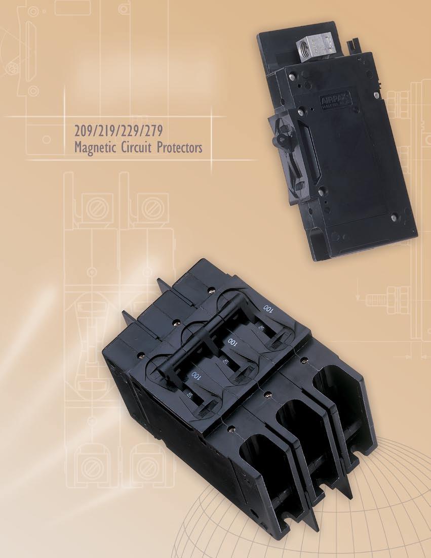
2 The 29, E-Frame circuit breaker combines power switching with accurate, reliable circuit protection 29/29/229 Magnetic Circuit Protectors 99 in a compact single or multipole 249 Power Selector Breaker System 2 unit. The unit is ideal for 29/29/229 Multi-Pole Circuit Protectors 22 branch circuit applications such as EDP, air conditioners, panel boards 229D & 279 Circuit Protectors 24 and lighting controls. 29/29/229 Configurations 24 The 29 is actually a family of circuit Operating Characteristics 26 breakers available in one through six pole assemblies with a variety of configurations 29/29/229 Delay Curves 27 and terminal styles to meet your 29/29/229 Specifications 2 application needs. First in this family is the 29, a general purpose E-Frame circuit breaker Ratings and Interrupting Capacities 2 which complies with UL Standard 489. Other Decision Tables 22 members of the family include the 29, for manual controller applications, which complies to UL Standard 58, the 229, for supplementary protectors applications, which complies to UL Standard 77, and the 299, a Special Construction version. Utilizing the hydraulic-magnetic principle, the 29 family adapts itself to local applications and environments. Temperature conditions, which affect fuses and other thermal devices, are not a concern. The magnetic /ampere turn principle minimizes nuisance tripping due to temperature variations. Inrush currents, due to ferroresonant transformers, lamps and capacitive filters, are now becoming more significant. Decision Tables for 249 Power Selector Breaker System 24 Recognizing the need for this type of protection, Airpax offers the unique inertial delay which is standard for all 5/6Hz time delay units, but may be deleted where inrush is not a problem. No extra cost or special order is required. The 29 family of circuit breakers withstands high pulses without tripping or affecting normal delay curves (see page 98). This performance, however, does not derate or sacrifice protection.
3 29 / 29 / 229 MAgnetic Circuit PROTECTORS Front Connected Solderless Connector (Back Mounted) A.562 [4.27].7 [7.78] MAX..22 [5.59] 2.6 [66.29].22 [3.99]. [38].2 [5.8].53 [3.46].485 [2.32] 2.75 [69.85].375 [34.92] 2.25 [575]. [28.58] º 35º 256 [54.76] 4.75 [2.65] 5.8 [47.32] [6.32] [23.4] 2X 6-32 MTG. INSERT 6 MIN. SCREW DEPTH [4.6].3 MAX. SCREW DEPTH [7.87] 3. MM ISO THD. OPTIONAL.22 [5.59] Terminal Style 29 E-Frame circuit breakers may be specified with either screw terminals, stud or solderless connectors. A choice of front or back connected terminal styles is available. The back connected terminal style is available with stud terminals only. Front terminal style is available with either screw terminals or solderless connectors. Refer to Sixth Decision Table on page 23 for front connected terminal information. Barriers for back connected terminal styles are supplied on multipole units only. Line and load connections may be made to either terminal and terminals will be identified as shown. Back Connected Stud Terminal (Front Mounted) A.7 [7.78] MAX..22 [5.59] 2.6 [66.29] 3.55 [97] 256 [54.76] 2.75 [69.85] 2.25 [575] [38].375 [34.92] 2X 6-32 MTG. INSERT 6 MIN. SCREW DEPTH [4.6].3 MAX. SCREW DEPTH [7.87] 3. MM ISO THD. OPTIONAL. [28.58] 3.55 [97] 4.75 [2.65] -5 AMPS -32 STUDS.625 ±.62 [5.88 ±.57] LONG 5- AMPS /4-2 STUDS.75 ±.62 [9.5 ±.57] LONG Note: Tolerance ± 5 [.38] unless noted. Dimensions in brackets [ ] are millimeters. 29/29/229 Magnetic Circuit Protectors 99

4 249 POWER SELECTOR BREAKER SYSTEM The 249 Power Selector Breaker System combines magnetic-hydraulic branch circuit overload protection and a power system selector switch in one device. The 249 is designed to allow selection of any one of two, three or four independent power systems. This is accomplished with fool-proof sliding-gate handle covers. The number of sliding covers is one less than the number of power systems. With this arrangement, it is impossible to switch ON more than one power system at a time. Since the 249 Power Selector Breaker System is listed as a Branch Circuit Breaker per UL 489 and power switching is accomplished by UL listed breakers, it is usually not necessary to include additional branch service protection. Standard options available include terminals for front or back connections, choice of trip time delay, current ratings to amperes and single or multi-pole sections. See page 26 for additional information. Trip Time Delay Three inverse time delays are available to permit close coordination with various loads. Delays 5 and 6 are short delays for electronic loads. Delays 52 and 62 are medium delays for mixed loads. Delays 53 and 63 are long delays for motor loads. Current and Voltage Ratings Single pole and multi-pole breaker ratings are available up to amperes, 24Vac or Vdc. The special configuration for Marine use has a 2V/24Vac rating for current rating up to amperes. Master Drawing Standard circuit breaker terminal and configurations are shown. For other types, consult factory Power Selector Breaker System
![249 Master Drawing (SEE TABLE).562 [4.27] 6-32 MTG. Insert 6 [4.6] MIN. screw depth.3 [7.87] MAX. screw depth (TYP) 2.6 [66.29].22 [3.99]. [38].53 [3.46].485 [2.32] +5 2.25 -.5 +.38 [575] -3 256 [54.](/docs-images/89/98504735/images/5-0.jpg "76] 2.75 [69.85] 5.8 [47.32]. [28.58].375 [34.92].2 (TYP.) [5.8] 4.75 [2.65].8 [2.32] MAX. Width 4.844 [23.4] 2.375 [6.32].22 [5.59].26 [26.6] (TYP.) 4X MTG. SLOT Clearance for 8-32 Screw (TYP.")
5 249 Master Drawing (SEE TABLE).562 [4.27] 6-32 MTG. Insert 6 [4.6] MIN. screw depth.3 [7.87] MAX. screw depth (TYP) 2.6 [66.29].22 [3.99]. [38].53 [3.46].485 [2.32] [575] [54.76] 2.75 [69.85] 5.8 [47.32]. [28.58].375 [34.92].2 (TYP.) [5.8] 4.75 [2.65].8 [2.32] MAX. Width [23.4] [6.32].22 [5.59].26 [26.6] (TYP.) 4X MTG. SLOT Clearance for 8-32 Screw (TYP.) - 32 or /4-2 Screw Terminals /4-2 Studs [97] [66.29].39 [ [9.53] 256 [54.76] 5. [38] 3.55 [97] 4.75 [2.65] (REF).75 [9.5] Number of Poles Width (236.83) Max (2.52) Max (57.89) Max (5.26) Max (52.63) Max. Note: Tolerance ± 5 [.38] unless noted. Dimensions in brackets [ ] are millimeters. 249 Power Selector Breaker System 2

6 29 / 29 / 229 MULTI-POLE CIRCUIT PROTECTORS Common-Trip Construction All multi-pole protectors contain an internal trip bar which opens all poles in the event of an overload in any pole. Handles are ganged externally for simultaneous actuation. Individual poles may differ in ratings, delays and configurations, providing an almost limitless number of combinations. Multi-pole protectors (up to 6 poles) easily satisfy special modern day circuitry. Series, shunt, relay and auxiliary switch construction add to the versatility of design engineering. Airpax s sales engineering force is ready to assist in proper unit selection, both for equipment protection and economical design. Three Phase, Four Pole Includes Control Protector Remote shutdown of equipment is sometimes necessary or desirable in today s sophisticated equipment. The 29 four pole assembly fills this need for three phase operation. Three of the four poles are designed for the circuit s proper operating current and over-current protection. The fourth pole may be designed for instantaneous tripping by logic circuitry, interlocks or from a manual remote site or control. The control power required would be quite low, with voltages from 5 to Vdc, or 5 to 24Vac available. The fourth pole construction is optional. It may be either series, shunt or relay, depending on the application required. When specifying, both the minimum trip voltage and Hz are required. Factory consultation is readily available. Front Connected Solderless Connector (Back Mounted) 2.72 (52.63) MAX..562 [4.27] [66.29] [7.78] MAX..22 [5.59].22 [3.99]. [38].2 [5.8] 2.75 [69.85].53 [3.46] 2.25 [575] [2.32] 256 [54.76] 5.8 [47.32] [23.4] See available mounting brackets below.375 [34.93]. [28.58] 4X 6-32 MTG. INSERT 6 MIN. SCREW DEPTH [4.6].3 MAX. SCREW DEPTH [7.87] 3. MM ISO THD. OPTIONAL 4.75 [2.65] [6.32].22 [5.59].26 [26.6] 2X MTG. SLOT CLEARANCE FOR 8-32 SCREW - 32 or /4-2 Screw Terminals.39 [9.9] Slotted Mounting Bracket terminal codes -2, -3, -5, -7, -3M, -5M, -7M Short Mounting Bracket terminal codes -2C, -3C, -5C, -7C 45 [3.68] SCALE: 3/ SCALE: 3/ 22 Multi-Pole Circuit Protectors

7 Multi-Pole Circuit Protectors 23

8 229D & 279 Circuit PROTECTORS 29 / 29 / 229 CONFIGURATIONS UL-5 Ignition Protection The 229D family is certified to UL-5 which covers Ignition Protected circuit protectors. This specification requires devices to be used in accordance with the requirements of U.S. Coast Guard and Fire Protection Standard for Pleasure and Commercial Motor Craft, ANSI/MFPA No. 32. The ratings available are amperes or less at 65Vdc or 24Vac. Maximum IC, amperes. Consult factory for application details. The 299D series is available with interlocking to prevent on board and shore power being used simultaneously. Combination of ON-OFF switching the protection function offers a simplified solution for your electrical systems. UL 489A Communications Equipment Protection The 279 Series complies with the requirements of UL 489A, Circuit Breakers for use in Communication Equipment, meeting the need for protection at higher DC voltages. The available ratings are amperes or less at 6Vdc. Maximum short circuit interrupting current is 5 amperes. The 279 series available only in a series trip configuration. Please consult Airpax for specific application details. Series Trip The most popular configuration for magnetic protectors is the series trip, where the sensing coil and contacts are in series with the load being protected. The handle position conveniently indicates circuit status. In addition to providing conventional overcurrent protection, it s simultaneously used as an on-off switch [97].75 [9.5] SEE NOTE A LINE LOAD Auxiliary Switch This is furnished as an integral part of a series pole in single or multi-pole assemblies. Isolated electrically from the protector s circuit, the switch works in unison with the power contacts and provides indication at a remote location of the protector s onoff status. (Applies to Series Trip Only) C NO NC 3.55 [97] 328 MAX. [79.45] REF. FROM BACK OF MOUNTING PANEL. [2.79].295 [7.49] -IREC4 -IREG4.563 [39.7].32 [7.92].75 [9.5] 87 [4.75] -IREC5 -IREG5 Quick Connect Terminals D Marine & 279 Communication Circuit Protectors 29/29/229 Configurations
9 29/ 229 CONFIGURATIONS Relay Trip This permits the overload sensing coil to be placed in a circuit which is electrically isolated from the trip contacts. The coil may be actuated by sensors monitoring pressure, flow, temperature, speed, etc. Other typical applications include crowbar, interlock and emergency/rapid shutdown circuitry. Trip may be accomplished by voltage or current, which must be removed after trip. Dual Coil Providing for both a voltage trip and a current trip function in a magnetic circuit protector is common practice. These two coil protectors provide remote or automatic opening of one or more circuits with a low level signal. The voltage coil will trip the protector instantaneously while the current coil provides normal inverse time delays. The voltage coil is not rated for continuous duty and therefore, the voltage must be removed when the breaker trips. Since both coils are housed within the same pole, the space savings are substantial. This option is not available with 64, 65 or 66 delays [97] SEE NOTE A. [25.4].25 [3.75] LINE LOAD RELAY RELAY Relay Trip LINE COIL COIL LOAD Dual Coil.75 [9.5] 9 [4.83] Shunt Trip The shunt trip is designed for controlling two separate loads with one assembly. The control is established by providing overload protection for the critical load. When the current through this load becomes excessive and reaches the trip point, the protector will open and remove power from both loads simultaneously. The total current rating of both loads must not exceed the maximum contact rating. SEE NOTE A LOAD LINE SHUNT Shunt Trip Voltage Trip Sometimes called dump circuits or panic trip circuits, these units make it possible to open main power contacts with lower power inputs from one or more sources. This configuration is becoming increasingly more important for sensitive circuitry and denser packaging in automation systems. Available in series, shunt or relay configurations [97].75 [9.5].25 [3.75] LINE V. COIL LOAD Dual Coil Note: Tolerance ± 5 [.38] unless noted. Dimensions in brackets [ ] are millimeters. A: -5 Amps, -32 Studs.625 ±.62 [5.88 ± 57 ] Long, 5- Amps, /4-2 Studs,.75 ±.62[9.5 ± 57 ] Long. 9 [4.83] 29/229 Configurations 25
10 operating characteristics Percentage of Rated Current vs Trip Time in Seconds Inrush Pulse Tolerance The table shown above provides a comparison of inrush pulse tolerance with and without the inertial delay feature for each of the 5/6Hz delays. Pulse tolerance is defined as a single pulse of half sine wave peak current amplitude of 8 milliseconds duration that will not trip the circuit breaker. The table at right provides a reference guide for selecting the inertial delay feature. Consult factory for further assistance. 26 Operating Characteristics

11 29 / 29 / 229 DELAY CURVES 5/6Hz Delay Curves (typ) A choice of delays is offered for 5/6Hz applications. Delay 6 is a short delay for general purpose applications. Delay 62 is long enough to start certain types of motors and most transformer and capacitor loads. Delay 63 is a long delay for special motor applications. Delays 64, 65 and 66 are the latest 5/6Hz delays with short, medium and long trip times respectively. The patented breaker design provides both increased tolerance to high inrush induced nuisance tripping and longer trip times at 6 percent. These delays are ideally suited for applications where thermal devices are presently used, such as motor protection or where short duration, high inrush currents are experienced. As shown in a typical motor start-up curve, the delay 66 will provide locked rotor and overload protection. Nuisance tripping is avoided, since acceptable short periods of overload will not trip the breaker. All trip curves and trip currents are specified with the breaker mounted in the normal vertical position at ambient temperature of +25 C. For test and measurement purposes, the breakers should not carry current prior to application of overload for calibration test. For other than vertical mount position, consult factory. DELAY DELAY DELAY /29/229 Delay Curves 27
12 29 / 29 / 229 / 279 Delay Curves 6Hz Delay Curves (typ) DELAY DELAY DELAY Delay Curves
13 29 / 29 / 229 DELAY CURVES DC Delay Curves (typ) (279 is available only with DC delays) 4Hz Delay Curves(typ) 5 2 DELAY DELAY DELAY 52 DELAY DELAY 53 DELAY /29/229 Delay Curves 29
14 29 / 29 / 229 specifications Coil Impedance Chart Trip Free Will trip open on overload, even when forcibly held on. This prevents the operator from damaging the circuit by holding the handle in the ON position. Trip Indication The operating handle moves positively to the OFF position on overload. Environmental Specifications Moisture and fungus resistance is provided by the use of moisture resistant finishes. Special springs and treatment for all ferrous parts eliminate inherent moisture-related problems. The use of fungi inert cases and handles avoids fungus-related problems. Current Ratings 29/29/229 may be supplied with these ratings: DC, 5/6Hz, 4Hz, to amperes. 279 types may be supplied with DC ratings only, to amperes. Approximate Weight Per Unit Single Pole 9 oz. Voltage Ratings On 29/29/229, voltages up to and including 24Vac, 5/6Hz or 4Hz, or Vdc are available. Multi-pole units can be supplied for 277Vac/48Vac, 5/6Hz. 279 types are available with a voltage of 6Vdc. All units will be marked with the standard maximum voltage. UL Listed breakers will be labeled with the UL listed voltage. Two Pole Three Pole Four Pole Five Pole Six Pole lb., 3 oz. 2 lb. 2 lb., 7 oz. 3 lb. 3 lb., 2 oz. Auxiliary Switch Ratings When supplied shall be S.P.D.T. configuration with a maximum rating of amperes 25Vac. Mounting Considerations A three-inch spacing must be provided between the circuit breaker and vent and any conductive surface. If closer than three inches is necessary, then an insulator must be installed on the conductive surface. Recommended Torque Specifications 6-32 mounting inserts 6-8 inch pounds M3 mounting inserts 4-5 inch pounds Solderless Connectors Connectors are rated AL9 CU. and accept either copper or aluminum conductors. Units are suitable for use with both 6 and 75 wire. Optional pressure plate for fine stranded wire is available. Contact factory for details. /4-2 screw terminals - 32 stud terminals M5 stud terminals /4-2 stud terminals 35-4 inch pounds 3-4 inch pounds 3-4 inch pounds 4-45 inch pounds 2 29/29/229 Specifications
15 29 / 29 / 229 / 279 Ratings and interrupting capacities Agency Approvals Agency Approvals 29 Circuit Breakers Current (A) Short Circuit Current Rating (SC) 29 Manual Motor Controllers Current (A) Short Circuit Current Rating (SC) Voltage (V) Frequency (Hz) Min. Poles UL/CSA VDE UL 489 & CSA VDE 65 DC DC /25 DC /6 only /24 5/ /24 5/6 2 only / Circuit Breakers (Marine) Voltage (V) Frequency (Hz) Min. Poles UL/CSA VDE UL489 & CSA VDE 25(2) DC Circuit Breakers for use in Communications Equipment Voltage (V) Frequency (Hz) Min. Poles UL/CSA VDE UL489A VDE 6 DC Agency Approvals 229 Supplementary Protectors Frequency Voltage (V) (Hz) UG FW Phase Min. Poles TC OL UL/CSA VDE UL 58 & CSA VDE DC A, D U2, / U, 5 4 DC A, D, U2, 5 / U, 5 4 /25 DC A, D, U, 5-3 DC A, D, U, 5 - /25 5/6 A, D U2, 5 - /25 5/6 A, D U, /6 A, D, U, /6 A, D, U, 5-277/48 5/6 A, D & C2, () / C2, - 277/48 5/6 A, D, 3 & U2, 5 / U, 5-347/6 5/6 A, D & C, () - 347/6 5/6 A, D, 3 & U, /6 A, D C2, () / C, - 6 5/6 A, D C2, () / C, - /25 4 A, D, U2, 5 / U, 2-229D Supplementary Protectors (Ignition Protected) Voltage (V) Frequency UG FW Phase Min. TC OL UL/CSA VDE UL5 & CSA VDE (Hz) Poles 65 DC A, D, 3 -, CSA - - U2, / - U, 25 5/6 A, D, 3, CSA - - U2, / U, - 229G Supplementary Protectors (Generator Use UL489 Field wired) Voltage (V) Frequency UG FW Phase Min. TC OL UL/CSA VDE UL77 & CSA VDE (Hz) Poles 277/48 5/6 A, D, U2, /6 5/6 A, D, U2, Supplementary Protectors (Marine) Voltage (V) Frequency (Hz) UG FW Phase Min. Poles Current (A) Short Circuit Current Rating (SC) TC OL UL/CSA VDE UL77 & CSA VDE 25 5/6 A, D, 3 & U, 5 - /25 5/6 A, D, U, /6 - - & /45 5/ Notes: () With 225A maximum series fuse Frequency Min. Voltage (V) (Hz) Poles UL/CSA VDE UL 58 & CSA VDE DC /24 5/ /24 5/ / /45 5/ / /48 5/ /48 5/ () / () - 6 5/ () Notes: () With 225 A maximum series fuse General notes All supplementary protectors are of the overcurrent (OC) type The family of protectors has been evaluated for end use application for use group (UG) A and D The terminals (FW) Terminals are coded as follows: Suitable for factory wiring only Line terminals evaluated for field wiring 2 Load terminals evaluated for field wiring 3 Line and Load terminals evaluated for field wiring The maximum voltage ratings for which the protectors have been tested are shown in the chart The current is the amperage range that the protectors have been tested The tripping current (TC) Tripping Current is coded as a percentage of the ampere rating Tripping current is less than % of ampere rating Tripping current is in the range of % to 35% of ampere rating 2 Tripping current is more than 35% of ampere rating 3 Tripping current is 35% and meets MCCB trip time requirements The overload rating (OL) - Designates whether the protector or family of protectors has been tested for general use or motor starting applications. tested at.5 times amp rating for general use tested at 6 times AC rating or times DC rating for motor starting The short circuit current rating (SC) The short circuit rating in amperes following a letter and number designating the test conditions and any calibration following the short circuit test is defined below: C Indicates short circuit test was conducted with series overcurrent protection U Indicates short circuit test was conducted without series overcurrent protection Indicates a calibration was not conducted as part of the short circuit testing 2 Indicates a calibration was performed as part of the short circuit testing 3 Indicates recalibration was performed along with the dielectric and voltage withstand for Suitable for Further Use rating Ratings and Interrupting Capacities 2

16 29 / 29 / 229 / 279 decision tables How to Order The ordering code for 29, E-Frame Circuit Breakers may be determined by following the steps in the decision tables shown here. The coding given permits a self-assigning part number for standard configurations. Factory part numbers are assigned to units with mixed ratings, combinations of styles or construction not listed in the Third Decision Table, etc. With these, it is suggested that order entry be by description and/or drawings, and a part number will be established. Additionally, it is standard policy to establish a factoryassigned part number whenever a descriptive drawing exists to insure cross reference, traceability and manufacturing control. When specifying a breaker for AC motor start or high inrush applications, the peak amplitude and surge duration should be specified for factory assistance in rating selection. 29 and 239 are UL listed circuit breakers under file no. E53739 per UL is a UL listed under file no. E9288 per UL 489A. 29 is a UL recognized Manual Motor Controller under file no. E467 per UL is a UL recognized supplementary protector under file no. E664 per UL 77. For example, the following is the code for a single pole breaker with series trip, 5/6Hz, medium inertial delay, 2/24Vac maximum voltage ratings, solderless connector with mounting foot added to the line side of the breaker to facilitate back panel mounting and a current rating of. amperes. To determine the ordering number of your particular 29 unit, simply follow the steps shown. You may use this number to place an order or as a reference for further questions you may have. Notes: A 6-32 inserts for front mounting are provided on all units. M3 ISO metric mounting inserts are available and are specified by adding -A at the end of the ordering code above. B The auxiliary switch is located on the right-hand pole (viewed from terminal end) unless specified otherwise. Auxiliary switches are available on all front or back panel mounts (series construction only). If more than one auxiliary switch is specified use 2R through 6R as required. C Line terminals are -32 screws for bus connection to amperes. Load terminals are -32 screws to 5 amperes and solderless connectors from 5 to amperes. D An anti-flashover barrier is supplied between poles on all multipole versions with -32 stud and /4-2 stud terminals per UL requirement. E The standard current values for % of rated current are those listed in the Seventh Decision Table. Non-listed values can be readily supplied, in general without delayed delivery. Please contact an Airpax office or sales representative. 22 Decision Tables
17 Terminal Terminal Connect Panel Mount - Solderless connector front front (Note A) -2 Solderless connector front back* -2C Solderless connector front back** screw ( amps max.) bus connect back (Note C)* -3C -32 screw ( amps max.) bus connect back (Note C)** screw (5 amps max.) front front screw (5 amps max.) front back* -5C -32 screw (5 amps max.) front back** -6 /4-2 screw ( amps max.) front front -7 /4-2 screw ( amps max.) front back* -7C /4-2 screw ( amps max.) front back** stud (5 amps max.) back front (Note D) -9 /4-2 stud ( amps max.) back front (Note D) -3M M5 x.8 screw ( amps max.) bus connect back (Note C)* -4M M5 x.8 screw (5 amps max.) front front -5M M5 x.8 screw (5 amps max.) front back* -6M M6 x. screw ( amps max.) front front -7M M6 x. screw ( amps max.) front back* -8M M5 x.8 stud (5 amps max.) back front (Note D) -9M M6 x. stud ( amps max.) front front (Note D) * Back panel mount style supplied with slotted mounting bracket. Solderless connector will accept #4 through copper or #2 through aluminum wire. ** Back panel mount style supplied with short mounting bracket. Decision Tables 23

18 Decision Tables for 249 Power Selector Breaker System How to Order To evolve a convenient ordering system for most applications, the following code has been developed. If a system is required which is not covered below, please consult factory or describe in detail. The number shown as an example describes a 2 volt, three section system, such as may be used on a boat with a port and starboard shore power receptacle and an AC generator. The breaker rating for the shore power is 3 amperes and for the generator 2 amperes in this example. /4-2 screw type terminals and a medium time delay are specified Decision Tables
209/219/229/249/279 SERIES HYDRAULIC MAGNETIC CIRCUIT PROTECTORS
 209/219/229/249/279 SERIES HYDRAULIC MAGNETIC CIRCUIT PROTECTORS Introduction The 209, E-Frame circuit breaker combines power switching with accurate, reliable circuit protection in a compact single or
APL/UPL, 205/295 Series Magnetic Circuit Protectors
 APL/UPL, 205/295 APL/UPL, 205/295 Series Magnetic Circuit Protectors Introduction 68 Single & Multi-Pole 69 Barriers 7 Configurations 72 Operating Characteristics 74 Delay Curves 75 Specifications 80 Decision
Magnetic Circuit Protectors 153. Multi-Pole Circuit Protectors 154. APL/UPL, 205/295 Barriers 155. Configurations 156. Operating Characteristics 158
 Magnetic Circuit Protectors 53 Multi-Pole Circuit Protectors 54 APL/UPL, 205/295 Barriers 55 Configurations 56 Operating Characteristics 58 Delay Curves 59 Specifications 64 APL/UPL Decision Tables 70
APG/UPG/IPG Series Existing Designs Only APG/UPG/IPG
 APG/UPG/IPG Series Existing Designs Only APG/UPG/IPG APG/UPG/IPG Series Hydraulic Magnetic Circuit Protectors INTRODUCTION IMPORTANT NOTICE: The APG/UPG is a legacy product and no new design-in orders
IELR Rail-Mount Series Magnetic Circuit Protectors
 IELR Rail-Mount IELR Rail-Mount Series Magnetic Circuit Protectors Introduction 92 Single Pole 93 Specifications 94 Operating Characteristics 95 Delay Curves 96 Approvals & Decision Tables 200 IELR Series
Single Pole Circuit Breakers 83 Multi-Pole Circuit Breakers 84 APGHX/UPGHX Breakers 86 APGX/UPGX Breakers 87 APGN/UPGN Breakers 88 APG/UPG Handles
 Single Pole Circuit Breakers 83 Multi-Pole Circuit Breakers 84 APGHX/UPGHX Breakers 86 APGX/UPGX Breakers 87 APGN/UPGN Breakers 88 APG/UPG Handles and Actuators 89 IPG Breakers 90 Configurations 9 Operating
E-Series General Specifications
 -Series General Specifications Ideally suited for higher amperage applications. Available with front and back mounting, screw terminals, stud terminals and heavy duty box wire connectors for solid wire
IELR Series
 IELR Series Rail-Mount Magnetic Circuit Protectors Introduction Poles Specifications Operating Characteristics Delay Curves Approvals Decision Tables 6 62 63 64 65 69 70 IELR Series Rail-Mount Hydraulic
Time Delay Values (E-Series)
") Time Delay Values (ESeries) AC Instantaneous 00 0 INSTANTANEOUS CURVE NO. 20 00 0 DC D.C. INSTANTANEOUS CURVE NO. 0 0. 0..0.0.00 200 300 400 500 700 800 900 0 200.00 200 300 400 500 700 800 900 0 200 Short
Time Delay Values (ESeries) AC Instantaneous 00 0 INSTANTANEOUS CURVE NO. 20 00 0 DC D.C. INSTANTANEOUS CURVE NO. 0 0. 0..0.0.00 200 300 400 500 700 800 900 0 200.00 200 300 400 500 700 800 900 0 200 Short
Ihr autorisierter Distributor: Neumüller Elektronik GmbH
 IELR Series Rail-Mount Magnetic Circuit Protectors Introduction Poles Specifications Operating Characteristics Delay Curves Approvals Decision Tables 6 62 63 64 65 69 70 Neumüller Elektronik GmbH Gewerbegebiet
Products :: Circuit Protection :: Hydraulic/Magnetic Circuit Breakers
 Products :: Circuit Protection :: Hydraulic/Magnetic Circuit Breakers Hydraulic/Magnetic Circuit Breaker B-Series B-Series PDF elibrary The B-Series hydraulic/magnetic circuit breakers are compact and
PERCENT OF RATED CURRENT
 A-D Series Time Delay Values PERCENT OF RATED CURRENT NOTES: UL489 C-Series Breakers available with Delay Curves 11, 12, 14, 16, 21, 22, 24, 26, 42, 44, 46. Delay Curves 11,12,14,16,21,22,24,26,42,44,46,52,54,56:
E-Series General Specifications
 -Series General Specifications Ideally suited for higher amperage applications. Available with front and back mounting, screw terminals, stud terminals and heavy duty box wire connectors for solid wire
C-Series. Circuit Breaker
 C-Series Circuit Breaker The C-Series hydraulic/magnetic circuit breakers are ideal for applications that require higher amperage and voltage handling capability in a smaller package. They are available
C-Series. Circuit Breaker
 C-Series Circuit Breaker The C-Series hydraulic/magnetic circuit breakers are ideal for applications that require higher amperage and voltage handling capability in a smaller package. They are available
1492-SP Supplementary Protectors
 Dual terminals provide wiring/bus bar flexibility and clamp from both sides to improve connection reliability Approval marks are easily visible on dome Terminal design helps prevent wiring misses Scratch-
IELR Rail-Mount Series Magnetic Circuit Protectors
 Series Magnetic Circuit Protectors Introduction 53 Single Pole 54 Specifications 55 Operating Characteristics 56 Delay Curves 57 Approvals & Decision Tables 6 IELR Series Hydraulic Magnetic Circuit Protectors
D-Series. Circuit Breaker
 D-Series Circuit Breaker Designed for snap-on-back panel rail mounting on either a 35mm x 7.5mm, or a 35mm x 15mm Symmetrical Din Rail, allowing rapid and simple mounting and removal of the breaker. It
UL 489 DIN rail branch circuit breakers
 UL 9 DI rail branch circuit breakers FAZ-A circuit breakers Product Overview UL 9 DI rail branch circuit breakers FAZ-A circuit breakers PRODUCT OVERVIEW Optimum and efficient protection Optimum product
Bulletin 1489 Circuit Breakers. Selection Guide
 Bulletin 1489 s Selection Guide Overview/Description Bulletin 1489-A s Energy-limiting design protects downstream components better than conventional breakers during short circuits Field-mountable options
Miniature Circuit Breakers and Supplementary Protectors. Contents
 . Optimum and Efficient Protection for Every Application Product Overview Features Optimum product quality, tested reliability and safety stand for best protection of personnel, installations and plant.
Products :: Circuit Protection :: Hydraulic/Magnetic Circuit Breakers
 Products :: Circuit Protection :: Hydraulic/Magnetic Circuit Breakers Miniature Hydraulic/Magnetic Circuit Breaker M-Series M-Series PDF elibrary The M-Series miniature hydraulic/magnetic circuit breakers
FAZ Supplementary Protectors, FAZ Miniature Circuit Breakers, P2 Disconnect Switches Overview
 FAZ Supplementary Protectors, FAZ Miniature Circuit Breakers, P2 Disconnect Switches Overview Supplementary Protectors / Miniature Circuit Breakers Page System overview 10/003 10/001 Supplementary protectors
MULTI 9 System Catalog UL Recognized NC100H Supplementary Protectors
 B Curve NC100H Supplementary Protectors Rating 1P 2P 3P 4P 80 MG27164 MG27175 MG27186 MG27197 MULTI 9 System Catalog UL Recognized NC100H Supplementary Protectors C Curve NC100H Supplementary Protectors
UL 489 DIN Rail Miniature Circuit Breakers
 UL 489 DIN Rail Miniature Circuit Breakers Product Overview................................................ 2 Product Selection................................................ 4 Accessories.....................................................
UL 489 DIN Rail Miniature Circuit Breakers
 UL 9 DIN Rail Miniature Circuit Breakers Product Overview................................................ Product Selection................................................ Accessories.....................................................
60103 Circuit Breaker
 6003 Circuit Breaker United States MINIATURE CIRCUIT BREAKER, 20/240VAC, 2A, CIRCUIT BREAKER TYPE: STANDARD Image not available Product Information Features and Specifications Circuit Breaker Type: Standard
MULTI 9 System Catalog UL Recognized C60N Supplementary Protectors
 UL Recognized C60N Supplementary Protectors B Curve C60N Supplementary Protectors 1 MG24110 MG24125 MG24140 MG24155 15 MG17406 MG17436 MG17461 1.2 MG17402 MG17432 16 MG24118 MG24133 MG24148 MG24163 1.5
Applying branch circuit breakers and supplementary protectors in North America
 Supersedes June 2017 FAZ-NA-L FAZ-NA FAZ Applying branch circuit breakers and supplementary protectors in North America Introduction Eaton offers three types of miniature circuit breakers for use in North
Mini Circuit Breakers, Fuse Blocks, and Electronic Circuit Protectors Specifications Bulletin Number 1492, 1692
 Technical Data Mini Circuit Breakers, Fuse Blocks, and Electronic Circuit Protectors Specifications Bulletin Number 1492, 1692 Topic Page 1489-M Miniature Circuit Breakers 1 1492-SP Supplementary Protectors
Applying branch circuit breakers and supplementary protectors in North America
 Product Application AP01102005E WMZT WMZS Applying branch circuit breakers and supplementary protectors in North America Introduction Eaton offers two types of miniature circuit breakers for use in North
24973 Circuit Breaker MINIATURE CIRCUIT BREAKER, 440VAC, 10A, CIRCUIT BREAKER TYPE: STANDARD
 United States 24973 Circuit Breaker MINIATURE CIRCUIT BREAKER, 440VAC, 10A, CIRCUIT BREAKER TYPE: STANDARD Image not available Product Information Features and Specifications Approvals: IEC 60947-2 Rated
TeSys IEC Contactors and Overload Relays
 TeSys IEC Contactors and Overload Relays Making High-Fault Short-Circuit Current Ratings Simple Schneider Electric is an industry leader in IEC contactors and overload relays, and is recognized as the
Magnetic and Hydraulic-Magnetic Circuit Breaker
 Description Single or multipole hydraulic-magnetic circuit breakers with trip-free - mechanism and toggle actuation. A choice of switching characteristics ensures suitability for a wide range of applications.
IAR/IUR/IER/CUR/CER Series 1RU Magnetic Circuit Protectors
 IAR/IUR/IER/CUR/CER Series RU Magnetic Circuit Protectors IAR/IUR/IER/CUR/CER [RU] Introduction 49 Poles & Terminals 50 Configurations 53 Delay Curves & Specs 54 Operating Characteristics 55 Hardware 56
UL 489 Cable-In / Cable-Out Branch Circuit Breaker
 Product Overview UL 9 Cable-In / Cable-Out Branch Circuit Breaker PRODUCT OVERVIEW Optimum and Efficient Protection Features Complete range of UL 9 listed DIN rail mounted miniature circuit breakers up
WMS SUPPLEMENTARY PROTECTORS
 WMS Supplementary Protectors Overview WMS SUPPLEMENTARY PROTECTORS Product Specification The WMS Supplementary Protector is a dual-rated product for both AC and DC supplies, in accordance with UL 1077
MG24434 Supplementary Protector SUPPLEMENTARY PROTECTOR, 240VAC, 16A, CIRCUIT BREAKER TYPE: STANDARD
 United States MG24434 Supplementary Protector SUPPLEMENTARY PROTECTOR, 240VAC, 16A, CIRCUIT BREAKER TYPE: STANDARD Product Information Features and Specifications For Use With: OEM Panels Approvals: UL
1.3. Miniature Circuit Breakers and Supplementary Protectors. Contents. WMZS Circuit Breaker. UL 1077 DIN Rail Supplementary Protectors
 . Miniature Circuit Breakers and Supplementary Protectors UL 077 DIN Rail Supplementary Protectors WMZS Circuit Breakers Contents Description WMZS Circuit Breaker Standards and Certifications................
1.2. Miniature Circuit Breakers and Supplementary Protectors. Contents. WMZ Circuit Breaker. UL 489 DIN Rail Miniature Circuit Breakers
 .2 WMZ Circuit Breakers Contents Description WMZ Circuit Breaker Standards and Certifications.............. Selection................ Product Selection....................... Accessories...........................
920 Remote Control (RC) Switches
 Switches") 920 Remote Control (RC) Switches ASCO is the global leader in power switching and controls ASCO 920 PRODUCT SPECIFICATIONS SWITCH ONLY (PANELBOARD MOUNTING) 1,2,3 () DIMENSIONS, IN.(MM) WIDTH HEIGHT DEPTH
920 Remote Control (RC) Switches ASCO is the global leader in power switching and controls ASCO 920 PRODUCT SPECIFICATIONS SWITCH ONLY (PANELBOARD MOUNTING) 1,2,3 () DIMENSIONS, IN.(MM) WIDTH HEIGHT DEPTH
ASCO 920 Remote Control (RC) Switches
 Switches") Maximum reliability and excellent value ASCO 920 Remote Control (RC) Switches ASCO 920 Remote Control Switch in Type Enclosure The ASCO 920 is designed as a feeder disconnect switch for load capacities
Maximum reliability and excellent value ASCO 920 Remote Control (RC) Switches ASCO 920 Remote Control Switch in Type Enclosure The ASCO 920 is designed as a feeder disconnect switch for load capacities
Magnetic and Hydraulic-Magnetic Circuit Breaker 8340-F...
 Magnetic and Hydraulic-Magnetic Circuit Breaker 830-F... Description Single and multipole magnetic circuit breakers with trip-free mechanism and toggle actuation. A choice of fast magnetic only or hydraulically
Magnetic and Hydraulic-Magnetic Circuit Breaker 8340-F...
 Description Single and multipole magnetic circuit breakers with trip-free mechanism and toggle actuation. A choice of fast magnetic only or hydraulically delayed switching characteristics (S-type MO or
IAG/IUG/IEG/CEG/LEG Single Pole Circuit Protectors 91. IAG/IUG/IEG/CEG/LEG Multi-Pole Circuit Protectors 92
 Single Pole Circuit Protectors 9 Multi-Pole Circuit Protectors 92 IAGH/IUGH/IEGH/CEGH/LEGH Circuit Protectors 93 IAGX/IUGX/IEGX/CEGX/ IAGZX/IUGZX/IEGZX/ CEGZX/LEGZX Rocker Circuit Protectors 94 IAGBX/IUGBX/IEGBX/CEGBX/LEGBX
Close Protection from Moeller. miniature branch circuit breakers miniature supplementary protectors
 Close Protection from Moeller miniature branch circuit breakers miniature supplementary protectors FAZ branch circuit breakers General Information... Selection Tables Trip Characteristic C - Box terminals...
The PCI Series. Precise power control for complex SCR applications. Phase Angle Fired SCR Power Controls AMPS VAC
 The PCI Series Phase Angle Fired SCR Power Controls 25-1200 AMPS 120-600 VAC Precise power control for complex SCR applications. ROBICON 1996 Distributed Worldwide by www.mcgoff-bethune.com Applications
9926 Series Branch Rated Circuit Breakers AC Version
 Branch Rated AC Version Hydraulic Magnetic Single pole and double pole versions 20/240 VAC, 50/60 Hz Up to 25A Just 3 mm wide Mounts on 35mm DIN-rail UL 489 listed, CSA C22.2 No. 5-02, CE VDE Ordering
Issued February DATA SHEET 5SX2 MCB. Based on Siemens Industrial Control Catalog
 Issued February 2011 DATA SHEET 5SX2 MCB Based on Siemens Industrial Control Catalog General Data Trip characteristics Tripping characteristics acc. to EN 60 898 Tripping characteristic A, -5 Type A characteristic
Section 4 Ground-Fault Protection Devices
 Multi 9 System Catalog Section 4Ground-Fault Protection Devices Section 4Ground-Fault Protection Devices Selection Table The Multi 9 System includes one UL Listed and three IEC rated product families that
Magnetic and Hydraulic-Magnetic Circuit Breaker 8340-T...
 Description ngle, two and three pole magnetic and hydraulic-magnetic circuit breakers with trip-free mechanism and toggle actuation. A choice of fast magnetic only hydraulically delayed switching characteristics
W69-X2Q12-20 Product Details
 TE Connectivity My Cart My Part Lists Sign In/Register English (Change) Have a Question? Chat with a Product Information Specialist What can we help you find? Products Industries Resources bout TE My ccount
Bulletin 1492-MC 1492-MCGA, -MCEA 1492-SP
 Bulletin Control Circuit and Load Protection Product Overview Bulletin -MC -MCGA, -MCEA -SP Type Branch Ground Fault Detection Features /V, V & Y/V rating A interrupt / in. per pole wide... A @ UL Circuit
The International Power Quality Resource
 3-Phase Reactors Line/Load Reactors Increase Drive System Reliability Filter Power Line Disturbances Reduce Harmonics Reduce Surge Currents Reduce dv/dt Extend Transistor Life Reduce Motor Noise and Temperature
Product Guide. UL 1077 DIN Rail Supplementary Protectors
 Product Guide UL 0 DIN Rail Supplementary Protectors UL 0 DIN Rail Supplementary Protectors Product Overview... Product Selection WMZS B Curve ( X I n Current Rating)..............................................
MULTI 9 System Catalog
 MULTI 9 System Catalog Class 80 CONTENTS Page Schneider Electric Brands Section Introduction... Section UL Rated Protection Devices... Section IEC 097- Rated Protection Devices... Section IEC Rated Ground-fault
IAG/IUG/IEG/CEG/LEG Series
 IAG/IUG/IEG/CEG/LEG Series Magnetic Circuit Protectors Introduction Poles Handles Configurations perating Characteristics Delay Curves Specifications Decision Tables 99 00 03 08 0 5 7 IAG/IUG/IEG/CEG/LEG
Control Circuit and Load Protection Products
 Selection Guide Control Circuit and Load Protection Products Bulletin Numbers 188, 1489, 1492, 1692 Circuit Protection Portfolio 1489-M Circuit Breakers Approved for branch circuit protection in the United
Selection Guide. Control Circuit and Load Protection
 Selection Guide Control Circuit and Load Protection Circuit Protection Portfolio 1489-M Circuit Breakers Approved for branch circuit protection in the United States and Canada, and certified as Miniature
D-Series CIRCUIT BREAKER
 D-Series CIRCUIT BREAKER Designed for snap-on-back panel rail mounting on either a 35mm x 7.5mm, or a 35mm x 15mm Symmetrical Din Rail, allowing rapid and simple mounting and removal of the breaker. It
PERFORMANCE SPECIFICATION
 INCH-POUND MIL-PRF-6106/13F 17 November 2011 SUPERSEDING MIL-PRF-6106/13E 10 November 2000 PERFORMANCE SPECIFICATION RELAY, ELECTROMAGNETIC, 25 AMPERE, 3PST, NO, WITH 2 AMPERE 1PDT AUXILIARY CONTACTS,
SECTION ENCLOSED SWITCHES AND CIRCUIT BREAKERS
 SECTION 262816 - ENCLOSED SWITCHES AND CIRCUIT BREAKERS PART 1 - GENERAL 1.1 RELATED DOCUMENTS A. Drawings and general provisions of the Contract, including General and Supplementary Conditions and Division
ST 200 M data sheet System pro M compact miniature circuit breakers for supplementary protection acc. to UL 1077
 MINIATURE CIRCUIT BREAKERS ST 200 M data sheet System pro M compact miniature circuit breakers for supplementary protection acc. to UL 1077 The ST 200 M miniature circuit breaker provides supplementary
SECTION DISCONNECT SWITCHES
 SECTION 16440 DISCONNECT SWITCHES PART 1 - GENERAL 1.01 RELATED DOCUMENTS A. Drawings and general provisions of the Contract, including General and Supplementary Conditions and other Division 01 Specification
RL Line/Load Reactors
 RL Line/Load Reactors Selection Table, Technical Details & Product Application Guide MTE HARMONIC COMPENSATED LINE/LOAD REACTORS help keep your equipment running longer by absorbing many of the power line
W91-X Product Details
 TE Connectivity My Cart My Part Lists Sign In/Register English (Change) Have a Question? Chat with a Product Information Specialist What can we help you find? Products Industries Resources bout TE My ccount
PD-Series General Specifications
 PD-Series General Specifications SmartGuard is an equipment ground fault protection device that combines hydraulic/magnetic circuit breaker and overload and short circuit protection and ground fault protection.
Selection Guide. Control Circuit and Load Protection
 Selection Guide Control Circuit and Load Protection Circuit Protection Portfolio 1489-M Circuit Breakers Approved for branch circuit protection in the United States and Canada, and certified as Miniature
Product Guide. UL 489 DIN rail miniature circuit breakers
 Product Guide UL 489 DIN rail miniature circuit breakers UL 489 DIN rail miniature circuit breakers Product Overview................................................ 2 Product Selection WMZT 10 kaic at
Miniature Circuit Breakers for Railway Applications
 Siemens AG 00 for Railway Applications BETA Low-Voltage Circuit Protection The miniature circuit breakers are used in fixed railway systems and rolling stock for protecting system components against overcurrent
Supplementary Circuit Protectors Type GSB63
 Supplementary Circuit Protectors Type GSB63 l Protection of circuits against short circuit and overload currents l UL1077 supplementary protection l 1,, 3 and 4 pole arrangements l 13 amperage sizes up
Model Number Structure
 Solid State Relays with Failure Detection Function G3PC CSM_G3PC_DS_E_1_1 Refer to Safety Precautions for All Solid State Relays. Detects failures in SSR used for heater temperature control and simultaneously
1510 MOTOR CONTROLLERS
 SECTION 262913- MOTOR CONTROLLERS PART 1 - GENERAL 1.1 RELATED DOCUMENTS A. Drawings and general provisions of contract, including general and supplementary conditions and Division 1 specification section,
ICS Regent. Relay Output Modules. Low Power and High Power (T3446L and T3446H) PD-6017
 PD-6017") ICS Regent PD-6017 Relay Output Modules Low Power and High Power (T3446L and T3446H) Issue 1, March, 06 Relay output modules provide control of eight user output loads. Two types of relay output modules
ICS Regent PD-6017 Relay Output Modules Low Power and High Power (T3446L and T3446H) Issue 1, March, 06 Relay output modules provide control of eight user output loads. Two types of relay output modules
Sentron 3VT circuit breakers Simply Smart: First choice for power distribution
 s Sentron 3VT circuit breakers Simply Smart: First choice for power distribution www.siemens.com/industry Sentron 3VT Molded Case Circuit-Breakers - 10-1600Amperes With the standard line of 3VT molded-case
SECTION SWITCHBOARDS
 SECTION 26 24 13 PART 1 - GENERAL 1.1 SUMMARY A. Work Included: 1. Switchboards 2. Commercial Metering Switchboards 3. Non-Utility Power Meters (Microprocessor-Based Metering Equipment) PART 2 - PRODUCTS
SECTION PANELBOARDS
 SECTION 16450 PART 1 - GENERAL 1.01 DESCRIPTION A. Section includes requirements for panelboards providing fault interrupting capability and overcurrent protective devices. 1.02 REFERENCE STANDARDS A.
Thermal-Magnetic Circuit Breaker 2216-S
 Thermal-Magnetic Circuit Breaker 226-S Description One and two pole thermal-magnetic circuit breaker in compact design with slide actuator, trip-free mechanism, various trip characteristics and optional
Introduction Circuit Protection
 Introduction Circuit Protection Weidmuller s DIN-rail mounted circuit breakers are available for use in applications where circuit protection must be able to distinguish between circuit overloads and short
Circuit Protectors CP31E, 32E, 33E, 34E CP31V, 32V, 33V, 34V
 CP3E, 32E, 33E, 34E CP3V, 32V, 33V, 34V CP-E and CP-V circuit protectors 250V AC 0.05A to 30A 65V DC 0.05A to 30A Description CP-E, CP-V circuit protectors have been specially developed for computers,
78 Series Electromechanical Relay Selection Guide
 78 Series Electromechanical Relay Selection Guide Specification 781 Series 782 Series 783 Series 784 Series Coil Voltages Configuration SPDT DPDT 3PDT 4PDT Contact Rating 15A 15A 15A 15A Base Socket 5
S&C IntelliRupter PulseCloser Fault Interrupter Overhead Source-Transfer Application
 Overhead Source-Transfer Application Detailed Functional Specification Guide 1.0 GENERAL 1.01 The automated distribution fault-interrupting system shall conform to the following specification. 1.02 The
Magnetically Actuated Safety Interlock Switches
 Conforms to EN10, EN292, EN020-1 CSA and BG approved Actual Size Magnetically Actuated Safety Interlock Switches Large selection choose from a large selection of contact configurations housed in plastic,
Description Basic devices with positive operation contacts. Standards IEC/EN 60947, EN , VDE 0660, UL, CSA
 Delivery program Contactor relay, 3N/O+1N/C, DC current Part no. DILA-31(24VDC) Catalog No. 276379 Eaton Catalog No. XTRE10B31TD EL-Nummer 4130206 (Norway) Product range DILA relays Application Contactor
E-STOP relays, safety gate monitors
 Safety relay for monitoring E-STOP pushbuttons, safety gates and light barriers. Approvals Block diagram Unit features Positive-guided relay outputs: 6 safety contacts (N/O), instantaneous 4 auxiliary
Type CBW58 Thermal Circuit Breaker Push to Reset Standard Profile
 Specifications: Amperage Range: 3A - 50A Voltage: 125 / 250 VAC, 50 VDC Frequency: 50-60 Hz Dielectric Strength: 1,500 VAC / 1 Minute Interrupting Rating: 3-50A 1000A @ 125/250VAC 3-30A 400A @ 125/250
PowerPact Q-Frame Molded Case Circuit Breakers and Switches (Types QB, QD, QG and QJ)
") PowerPact Q-Frame Molded Case Circuit Breakers and Switches (Types QB, QD, QG and QJ) Catalog Class 0CT00R/0 0 CONTENTS Description..............................................Page Description.............................................
PowerPact Q-Frame Molded Case Circuit Breakers and Switches (Types QB, QD, QG and QJ) Catalog Class 0CT00R/0 0 CONTENTS Description..............................................Page Description.............................................
TeSys contactors From 115 to 2750 A
 Selection guide From to 0 A Applications Control of all types of motor for standard or severe duty applications Control of resistive, inductive and capacitive circuits: heating, lighting, cos j rectification,
Voltage Dip-Proofing Inverter
 Voltage Dip-Proofing Inverter DPI54S / 54L Series Models 120V & 208/230 50/60Hz Contents: Introduction...3 Theory of operation...3 Specifications...5 Up-time considerations...6 Installation Guide...7 Test
MODEL NUMBERS OUTPUT SPECIFICATIONS 1 Zero Voltage and Random Turn-On Switching Panel Mount 600V Transient Capability Internal Snubber 110 & 125A Mode
 MODEL NUMBERS OUTPUT SPECIFICATIONS 1 Zero Voltage and Random Turn-On Switching Panel Mount 600V Transient Capability Internal Snubber 110 & 125A Models Available Integrated Overvoltage Protection by Automatic
Technical data. Housing Polyamide housing PA 66, self-extinguishing V0 acc. to UL 94. Supply Rated supply voltage (U n
 Safety module CS AT 0 Module for emergency stops, end position monitoring for movable guards with delayed contacts at the opening of the input channels, semiconductor outputs (e.g. light barriers and magnetic
COMPACT LED CONVERTERS 48 V
 COMPACT LED CONVERTERS 48 V EasyLine 48 V 186691, 186692 Typical Applications Shop lighting for 48 V systems Furniture lighting EasyLine 48 V VERY COMPACT SHAPE VERY LOW RIPPLE CURRENT LONG SERVICE LIFETIME:
Model Number Structure
 Solid State Relays CSM DS_E_3_1 Compact, Low-cost, SSR Switching 5 to 20 A Wide load voltage range: 75 to 264 VAC. Both 100-V and 200-V loads can be handled with the same model. Dedicated, compact aluminum
ICS Regent. AC Guarded Digital Output Module 110 VAC (T3464) PD-6021
 PD-6021") ICS Regent PD-6021 AC Guarded Digital Output Module 110 VAC (T3464) Issue 1, March, 06 AC Guarded digital output modules provide guarded switching of user-supplied 110 AC voltages to a maximum of sixteen
ICS Regent PD-6021 AC Guarded Digital Output Module 110 VAC (T3464) Issue 1, March, 06 AC Guarded digital output modules provide guarded switching of user-supplied 110 AC voltages to a maximum of sixteen
MAINTENANCE MANUAL. EDACS REDUNDANT POWER SUPPLY SYSTEM 350A1441P1 and P2 POWER MODULE CHASSIS 350A1441P3, P4, AND P5 POWER MODULES TABLE OF CONTENTS
 MAINTENANCE MANUAL EDACS REDUNDANT POWER SUPPLY SYSTEM 350A1441P1 and P2 POWER MODULE CHASSIS 350A1441P3, P4, AND P5 POWER MODULES TABLE OF CONTENTS SPECIFICATIONS*... 2 INTRODUCTION... 3 DESCRIPTION...
Voltage Dip-Proofing Inverter
 Voltage Dip-Proofing Inverter DPI53S / 54L Series Models 120V & 208/230 50/60Hz LEADERS IN VOLTAGE DIP-PROOFING Contents: Introduction...3 Theory of operation...3 Specifications...5 Up-time considerations...6
PERCENT OF RATED CURRENT
 A-D Series Time Delay Values PERENT OF RATED URRENT NOTES: UL489 -Series Breakers available with Delay urves 11, 12, 14, 16, 21, 22, 24, 26, 42, 44, 46. Delay urves 11,12,14,16,21,22,24,26,42,44,46,52,54,56:
Type CBW57 Thermal Circuit Breaker Push to Reset Low Profile
 Specifications: Push to Reset - Low Profile Amperage Range: 3A - 30A Voltage: 125 / 250 VAC, 32 VDC Frequency: 50-60 Hz Dielectric Strength: 1500 VAC / 1 Minute Interrupt Rating: 3-30A 1000A @ 125/250
Selection Guide. Control Circuit and Load Protection. Allen-Bradley 1489-M2C020
 Selection Guide Control Circuit and Load Protection Circuit Protection Portfolio 1489-M Circuit Breakers Approved for branch circuit protection in the United States and Canada, and certified as Miniature
D15CC55UNVD K/KS. UNV DALI Dimming LED Driver 1500mA Constant Current Output Class 2, 55W Output DALI Dimming to 1% Performance.
 UNV DALI Dimming LED Driver 1500mA Constant Current Output Class 2, 55W Output DALI Dimming to 1% Performance Input Voltage 120 ~ 277 Vac Input Current Max 0.56 /120V 0.24/277V Input Power Max 63W Input