Roof Truss Roller Press, Tables and Jigging
|
|
|
- Erica Mason
- 5 years ago
- Views:
Transcription


1 RoofTracker II Roof Truss Roller Press, Tables and Jigging August 2015 Page 1
2 Table of Contents Equipment Introduction to the Equipment Restricted Zone Truss Terminology Parts of a Truss Important Notes Operating Procedures Stopping the Machine Indicators Operator Control Interface Mechanisms Normal Operating Conditions Restarting Operation Safety Features VFD and Brakes Bumpers and Safety Controllers Light Curtains Tables Operator Control Interface Operating the Tables Operating the Transfer Rollers Pneumatics Operation Page Setting Up for Operation Manual Jigging Introduction to Jigging Slider Pad Aisle Pads Quiz Page Page 2

3 Equipment Introduction to the Equipment Purpose: The primary function of the RoofTracker II roof truss roller press system is to press MiTek connector plates into roof trusses to connect roof truss components. Overview The RoofTracker II roof truss roller press system consists of a gantry head, which houses the roller that causes the initial embedment of the connector plates; a set of tables that holds and supports the truss and gantry head; a Stand-Alone Conveyor system; and a Finish Roller that completes the plate embedment process. The system components can be seen in image below. NOTE: Throughout this training, the term RoofTracker press is used to refer to the entire system. Page 3

4 Equipment Restricted Zone Know the Restricted Zone Page 4

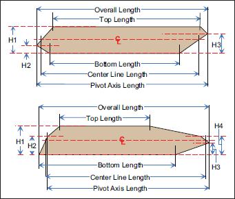
5 Truss Terminology Truss Terminology Terminology Diagram Page 5
6 Parts of a Truss Page 6
 days to prolong the life of the wheels.")
7 Important Notes Do not allow the gantry head to sit in one place for a long period of time after installing it on the table and parking stand assembly. This may cause flat spots to form on the polyurethane wheels. Move the gantry head at least every three (3) days to prolong the life of the wheels. Page 7
, follow these guidelines when stopping the gantry head during normal operation: To stop the gantry head during normal operation, release the joystick and let the gantry head coast to a stop.")
8 Operating Procedures Stopping the Machine Stopping During Normal Operation To significantly increase the life of machine components (such as brake pad, bearing, chain, wheels, motor, etc.), follow these guidelines when stopping the gantry head during normal operation: To stop the gantry head during normal operation, release the joystick and let the gantry head coast to a stop. Do not use the E-stop for routine stopping as this will cause unnecessary wear on components. To park the gantry head on the parking stands, release the joystick with sufficient time for the gantry head to stop. Do not allow the parking stand flag to break the light beam as this will imitate an E-stop and cause unnecessary wear on components. Emergency Stop Push the red emergency stop (E-stop) button next to the joystick to cease power transmitting to the control circuit and stop motion of the gantry head. To release the E-stop, pull up on the pushbutton so it returns to its raised position. The E-stop button on the joystick control panel is shown here. When an E-stop pushbutton is actuated, the center is illuminated in red. Page 8
9 Operating Procedures Stopping the Machine (cont) Light Curtains Operation of the light curtains is discussed later in this chapter. To stop the machine using the light curtains, a solid object must pass through the light beam, interrupting the transmission of the beam between the transmitter bar and receiver bar. Light Curtain and Bumper Laser Scanner The laser scanner is provided only if the equipment has the optional High Bottom-Chord Platform that is at the same height as the table tops. In this instance, a safety device scans the predetermined safety zone to ensure that the platform does not come into contact with other people who may be inside the restricted zone area. The gantry head will stop if a solid object passes through the scanner s light beam inside the scanner s safety zone. Bumpers The machine will stop when something causes a bumper to retract. A bumper is located on each corner of the gantry head to provide additional safety control. The gantry head bumpers automatically reset themselves when fully extended. If your machine has a Top-Chord platform (optional item) or a High Bottom-Chord platform, the bumpers have been removed on the end with the platform. Page 9
 position supplies electrical power to the entire machine.")
10 Operating Procedures Stopping the Machine (cont) Disconnect Switch The disconnect switch is located on the main electrical enclosure. See the image shown here. Turning the disconnect switch to the ON (vertical) position supplies electrical power to the entire machine. To remove power to the machine, turn the disconnect handle to the OFF (horizontal) position. The disconnect switch should always be turned off when the machine is not in use. Disconnect Switch Page 10

11 Operating Procedures Indicators Light Stack There is a light stack located on top of the gantry head. It has 4 different beacon lights that visually show the status of the machine. See the image shown here. Indicators on Light Stack and Horn Assembly For solutions to faults, refer to the appropriate component section. 1. Red indicates an E-stop is actuated. 2. Amber (yellow) indicates the gantry head is in motion, either direction. 3. Blue blinks when warning that the drive chain s motion is nearing an unsafe condition. NOTE: The light is solid blue when the drive chain is in an unsafe condition which could affect stopping capabilities 4. Red: Indicates a VFD fault. Ready Indicator Lights The two lights on either side of the horn are the Ready indicator lights. If the gantry is ready to move in that direction, the appropriate light stays illuminated. If one or both of those lights are off, the gantry cannot move in that direction. Begin by checking for other faults, or a barrier blocking the light beam. Horn The horn sounds for a few seconds prior to machine movement. When the horn stops, the gantry head will begin motion. The beacon remains blinking while the gantry head is moving. Page 11


12 Operating Procedures Indicators (cont) Hour-Meter An hour-meter is located on the main enclosure. See Figure 5-4. It records the number of operating hours, which is the time the gantry head is in motion. Refer to this meter to determine a maintenance schedule. Indicators on Front of Main Enclosure Safety Controller Indicator Lights The safety controller ensures that the safety features on this machine are working properly. It is located in the main electrical enclosure. Indicator lights on the front of the safety controller unit communicate the Operating Mode and errors that may occur. Refer to page 64 for more information. Laser Scanner Indicator Lights There are 2 lights or light covers on the front of the main electrical enclosure, shown here. For machines equipped with a laser scanner under a table-top-high operator s platform, these lights illuminate to show when the laser scanner is ready, or when it is dirty and needs to be cleaned. For machines that do not have a laser scanner, the light covers are present on the front of the main electrical enclosure, but the lights are not connected to power and will not be used unless a laser scanner is installed later. NOTE: There are additional indicator lights on the laser scanner itself. For more information about the laser scanner, refer to Laser Scanner section of the RoofTracker II Operators Manual. Page 12
13 Operating Procedures Operator Control Interface Mechanisms Getting Familiar With the Operation Your RoofTracker II press is operated by a joystick. The joystick is mounted on a panel attached to the gantry head called the operator control station (or operator station). Joystick and Control Panel A platform is attached to the gantry head for the operator to stand on. Reset The blue RESET button enables all safety monitoring devices. The operator must press RESET before the directional indicator lights will come on. The RESET button shall be pressed and released for the gantry head to work. If the RESET button is continually held in, the gantry head will coast to a stop. Page 13

14 Operating Procedures Operator Control Interface Mechanisms (cont) Joystick and Control Panel Joystick To operate the equipment with a joystick, press the blue RESET button on the operator control station. Then, press and hold the white button on the joystick handle while pushing the handle in the direction the gantry head should move. NOTE: The operator must keep the white button on the joystick depressed for movement to continue. Standard Operator Platform To stop motion, release the white button on the joystick handle. The gantry head decelerates and comes to a complete stop. Control Panel Operator Platform The operator platform is a required feature for a gantry using a joystick operator control interface. It is a raised platform that the operator(s) stands on, allowing the operator(s) to ride along with the gantry head as it travels. The standard platform is located on the bottom-chord side of the table line. Platform Platform Bumper Page 14


15 Operating Procedures Operator Control Interface Mechanisms (cont) Getting to Know Your Pendant Control Station (optional) The pendant control station is an optional operator control interface that is shown here. It is a hand-held device connected to the machine by a cable. There are four (4) pushbuttons on the pendant. Start The green START button enables all safety monitoring devices. The operator must press START before the directional indicator lights will come on. Directional Buttons When the directional indicator lights on the electrical enclosure are lit, press and hold one of the black directional buttons on the pendant to begin movement of the gantry head. On 1-enclosure systems, the buttons read RIGHT and LEFT. The REVERSE and FORWARD buttons are on 2-enclosure systems. Reverse is toward the right when facing the disconnect switch and forward is to the left. NOTE: When you release a directional button, the gantry head decelerates and eventually comes to a complete stop. Page 15
16 Operating Procedures Normal Operating Conditions Operating Under Normal Conditions 1. Turn the disconnect handle to the ON (vertical) position. 2. Set up the truss configuration and jigging. Refer to the Setting Up for Operation Jigging section of this manual. 3. Verify the following: a) No fault lights are lit on the light stack. b) Both of the Ready indicator lights are lit. c) Safety detection zones are clear and all safety devices are in normal operating condition. 4. Press and release the RESET button. 5. Move the gantry head in the desired direction: a) Press and hold the white button on top of the joystick. b) Push or pull the joystick in the direction the gantry head should move. c) Release the white button or the joystick to bring the gantry head to a gradual stop. Page 16
17 Operating Procedures Normal Operating Conditions (cont) 6. Remove the truss from the table and place it on the Stand-Alone Conveyors. a) For systems without ejectors, manually slide the truss over onto the conveyors. b) For systems using pneumatic ejectors and receivers: 1) Remove all slider pads and ensure the gantry head is not parked on top of an ejector. 2) Turn the setup s pilot valve handle. Refer to the Pneumatics Operation section for more detail. With end-eject systems (or side-eject that is not an auto-eject), manually push the truss from the ejectors to the receivers or conveyor. With an auto-eject system, the truss will slide onto the Stand- Alone Conveyors automatically. 3) Turn the setup s pilot valve handle back to its original position. 7. Repeat the steps above for the next truss. NOTE: Move the gantry head at least every three (3) days to prolong the life of the wheels. Sitting in one place may cause flat spots to form on the polyurethane wheels. Page 17
18 Operating Procedures Normal Operating Conditions (cont) Page 18

19 Operating Procedures Restarting Operation If the machine stopped because you released the joystick, both Ready indicator lights should still be on. You can continue motion in either direction by pressing the joystick button and moving the joystick in the direction the gantry should go.. If the machine stopped because a safety device was activated, remove the barrier and reset the system by following the procedure below. When the light beam or bumper experiences an interference on one side of the gantry head, the gantry head can still be operated in the opposite direction. 1. Remove the barrier that was detected by the light beam or bumper. To move the gantry head in the opposite direction: a) Press and hold the white button on top of the joystick. b) Push or pull the joystick in the direction the gantry head should move. c) Release the white button or the joystick to stop the gantry head s travel. The deceleration stop feature is suspended until the system is reset by pressing the RESET button. 2. Press and release the RESET button. Verify that the two Ready indicator lights (on the horn) are illuminated. If they are not, there is a physical barrier or electrical problem. 3. Resume operation as normal. Page 19
20 Safety Features VFD and Brakes The VFD (variable frequency drive) is inside the VFD enclosure. It is the enclosure to the right of a bottom-chord operator platform. If the VFD experiences a fault, a fault description will appear on the VFD display, but the beacon stack may also provide clues. NOTE: Maintenance personnel should refer to the VFD and Encoder section of the Operators Manual for help with the faults. Bumper NOTE: The fault that needs to be understood by operators is the Motion Fault. Motion Faults When a drive chain s motion is nearing an unsafe condition, the blue beacon on the light stack flashes to notify the operator that this matter should be addressed as soon as possible. If this happens: 1. Contact your maintenance department to schedule the necessary maintenance. 2. Press the RESET button on the operator control station. 3. Continue operating the machine as normal until the problem is fixed. Page 20
21 Safety Features VFD and Brakes (cont) Motion Faults (cont) When a drive chain s motion indicates the machine is in an unsafe condition, the blue beacon on the light stack illuminates solid blue and the machine will not operate. If this happens: 1. Contact your maintenance department to determine the problem. Bumper 2. Refer to the maintenance information. NOTE: The maximum safe stopping distance in an emergency stop situation is 11-1/2 inches. NOTE: The air gap in the brake motor may need to be adjusted as the brake pad wears down. The air gap does not affect the stopping distance, but a worn break pad will burn up the motor. Other VFD Faults For other VFD faults, refer to your electrical schematic for VFD settings and jumper details. All VFD faults are explained in the VFD manual from the VFD manufacturer. The VFD manual was provided when your equipment was purchased and installed. Page 21


22 Safety Features Bumpers and Safety Controllers Bumpers The bumpers located on the corners of the gantry head provide additional safety control. One is shown here. When a bumper collapses, it passes in front of the light curtain and causes the machine to stop its motion in the direction associated with the collapsed bumper. The rotation of the roller also stops at this time. Light Curtain Bumper Safety Controller The safety controller ensures that all safety features on this machine are working properly. It should not require any additional operation, outside of the normal operating procedures. If the machine will not operate, the safety controller is a good place to start troubleshooting. Scanner (optional) Some machines are equipped with an optional laser scanner. It is an optical safety sensor that determines the location of objects in the pre-determined zone. It does so by emitting a laser light, which is reflected back to it, so no additional receiver is required. Page 22

23 Safety Features Light Curtains Light curtains are presence-sensing devices designed to guard personnel working around moving machinery. RoofTracker II presses use a two-beam light curtain set on both sides of the gantry head. A light curtain set consists of a receiver bar and a transmitter bar. The diagram shown here is a typical light curtain system. Although this diagram shows a three-beam light curtain set, the concept and indicators are the same. Bumper When a beam between the two bars is broken, the machine will stop its motion in the direction associated with the interrupted light curtain set. The rotation of the roller also stops at this time. Once the interruption has been removed, the operator must press the RESET button and the directional button to restart the machine. When a light beam interruption occurs, the gantry head is still able to move in the opposite direction. Page 23

24 Tables Operator Control Interface The pneumatic system controls the ejectors on the tables and the receiver stands. The entire length of tables can be controlled by any one pilot valve if all ball valves are open, or each setup can be operated independently. You can remove any table from the setup by turning off the table valve. Refer to your gantry head or MatchPoint manual for information on operating gantries or automated jigging. This image shows the setup pilot valve that controls the ejectors and receivers, and explains how the position of the valve will affect the ejectors and receivers. Bumper See the next page for and overview of the Control Mechanisms Page 24
 Control")

25 Tables Operator Control Interface (cont) Control Mechanisms Functions of Control Mechanisms Page 25
26 Tables Operating the Tables 1. Set up the truss configuration and jigging. Refer to the Setting Up for Operation Manual Jigging section of this manual. 2. Refer to your gantry manual for gantry operation. 3. When you are finished pressing the truss, remove the truss from the table and place it on the Stand- Alone Conveyors. a) For systems without ejectors, manually lift or slide the truss over onto the conveyors. b) For systems using pneumatic ejectors and receivers, refer to the Pneumatics Operation section. Page 26

27 Tables Operating the Transfer Rollers Operating the Transfer Rollers (Auto-Eject, High-Slope, and Long Throw Systems) The transfer rollers will operate continuously once they are turned on. 1. Turn on power to the transfer rollers. The power switch is located in the transfer roller control box, usually next to the control box for your Stand-Alone Conveyor system. 2. Use the FORWARD/REVERSE button to start the motion of the transfer rollers. 3. When you are finished using the transfer rollers, use the STOP button to stop the motion of the transfer rollers. Page 27

28 Tables Pneumatics Operation Operating the Entire Pneumatic System as One System After the connector plates have been pressed into the truss: 1. Remove ALL slider pads from the tables. 2. Ensure the ball valves between each setup on the 22-mm tubing are open. Bumper 3. Ensure all table valves are open. 4. Ensure all pilot valves are in the neutral position. 5. Actuate any pilot valve by turning the handle to the up position. a) The ejectors will lift the truss off the table. b) On side-eject systems, the receivers will also raise. 6. Remove the truss from the tables. a) On side-eject and tall side-eject systems, someone must push or pull the truss from the ejectors onto the receivers. b) On auto-eject, high-slope auto-eject, and long throw systems, the truss will slide over the transfer rollers and onto the conveyors. c) On end-eject systems, push or pull the truss across the pop-up rollers to transfer the truss to the end of the table line and onto the conveyors. Page 28
29 Tables Pneumatics Operation (cont) 7. Turn the handle (on the pilot valve previously actuated) to the down position. a) The ejectors will retract into the table. b) On side-eject systems, the receivers will retract and place the truss onto the conveyors. 8. If building another truss, return the handle to the neutral position so any pilot valve in the system can be used. Bumper NOTE: All pilot valves must be in the neutral or down position for a setup to operate. Page 29
30 Tables Pneumatics Operation (cont) Operating Two or More Setups Independently of Each Other 1. Close the ball valve(s) on the 22-mm tube that is between the setups that are to be controlled independently of each other. 2. Ensure all table valves are open on the tables involved. 3. Actuate the setup pilot valve by turning the handle to the up position. Bumper a) The ejectors will lift the truss off the table. b) b) On side-eject systems, the receiver will also raise. 4. Remove the truss from the tables. a) On side-eject systems, someone must push or pull the truss from the ejectors onto the receivers. b) On auto-eject systems, the truss will slide over the transfer rollers and onto the conveyors. 5. Turn the handle (on the pilot valve previously actuated) to the down position. a) The ejectors will retract into the table. b) On side-eject systems, the receivers will retract and place the truss onto the conveyors. 6. If building another truss, return the handle to the neutral position so any pilot valve in the system can be used. Page 30
31 Tables Pneumatics Operation (cont) Removing a Table From a Cycle: 1. Close the table valve on the table or tables not involved in this cycle. 2. Continue to operate the rest of the setup as normal. Bumper To Auto-Eject, High-Slope Auto-Eject and Long Throw Customers: The transfer rollers are part of the operating equipment, but have no pneumatic functions. They constantly run while power is on. The rollers grab the truss as it slides off the auto-ejector and place it onto the conveyors. Page 31
32 Setting Up for Operation - Manual Jigging Introduction to Jigging To set up each truss configuration, jigging must be used. The jigging instructions are found here for manual jigging. Refer to your MatchPoint manual for information on MatchPoint automated jigging. NOTE: MiTek is unable to provide support for jigging other than MatchPoint automated jigging or manual jigging purchased from MiTek. Bumper Your jigging has a Standard Stop Set containing the basic components for an assembly line workstation for approximately four to six tables (30-45 ft of assembly line length). In addition to the Standard Stop Set, you will also need a fixture set. a) Use the Slotted Fixture Set with slotted-top tables that do not use a laser projection system, b) Use a Laser Jigging Fixture Set with systems that use a laser projection system. See the next 2 pages for images of Pucks for Standard Stop Set and Straight Stop for Slotted Fixture Set You can add to your jigging collection at any time by contacting MiTek Customer Service. There is also a replacement kit available for slotted-top tables that includes the most common parts that need to be replaced periodically to keep your jigging in good operating condition. Additional information can be found in the instruction booklets that shipped with each set. Refer to the Replacement Parts appendix of the Operations Manual for the replacement kit part number. Refer to the Maintenance chapter of the Operations Manual for preventive maintenance tips. Page 32
 Pucks for Standard Stop Set, Assembled Bumper")
33 Setting Up for Operation - Manual Jigging Introduction to Jigging (cont) Pucks for Standard Stop Set, Assembled Bumper Page 33
 Straight Stop for Slotted Fixture Set, Assembled Bumper Page")
34 Setting Up for Operation - Manual Jigging Introduction to Jigging (cont) Straight Stop for Slotted Fixture Set, Assembled Bumper Page 34

35 Setting Up for Operation - Manual Jigging Slider Pad The slider pad is designed to cover parts of the ejector slot so that plates can be embedded into the lumber over the ejector slot if required. You must insert a slider pad under the lumber to guarantee complete embedment of the plate. 1. Slide the pad into the ejector slot from either end of the table. The top surface of the slider pad should be even with the top of the table as shown here. 2. Arrange the slider pad so it is located directly under the connector plate location. 3. To remove the slider pad, slide it completely out of the ejector slot. Bumper Inserting a Slider Pad into an Ejector Slot Page 35

36 Setting Up for Operation - Manual Jigging Aisle Pads The aisle pads are designed enable plate embedment into truss lumber as it crosses the walk-through aisle between the tables if a connector plate must be embedded at that point. You must insert an aisle pad under the lumber to guarantee complete embedment of the plate. 1. Slide the aisle pad between two tables from either end of the tables. The aisle pad s flanges should be resting on the lip of each table as shown in this image. Bumper 2. Arrange the aisle pad so it is located directly under the connector plate location. 3. To remove the aisle pad, slide the pad out from between the tables. Two Types of Aisle Pads Page 36
37 Quiz 1. Throughout this training, the term RoofTracker press is used to refer to? a) The press b) The tables c) The entire system d) None of the above 2. The disconnect switch is located where? a) The press b) The main electrical enclosure c) Each table d) The operators position 3. What is the light color and status of the light stack when the drive chain is in an unsafe condition? a) Yellow, Solid b) Red, Blinking c) Yellow Blinking d) Blue, Solid 4. For movement to continue the operator must do what to the joystick white button? a) Depress and release b) Click twice and release c) Depress and hold down d) Click twice and hold down 5. The fault that needs to be understood by operators is the motion fault? a) True b) False 6. What is the maximum safe stopping distance in an emergency stop situation? a) 11 ½ b) 12 ½ c) 13 ½ d) 14 ½ 7. Light curtains are presence-sensing devices designed to guard personnel working around moving machinery? a) T b) F 8. All pilot valves must be in what position for a setup to operate? a) Up b) Down c) Neutral d) Any position will work 9. Slider pads are designed to protect workers from ejectors? a) True b) False 10. Aisle pads are designed to enable plate embedment at walkthroughs? a) True b) False Page 37
Service Bulletin. MiTek. RoofTracker Roof Truss Roller Press. Machinery Affected: Adding an Operator Platform. Machinery Division
 MiTek Machinery Division Service Bulletin Machinery Affected: Document: Title: Applies To: RoofTracker Roof Truss Roller Press SB171 Adding an Operator Platform Frames 51 and Lower Copyright 2006 MiTek.
Removal and Installation8
 8 Screw Types 8-4 Top Cover Assembly 8-5 Left Hand Cover 8-6 Right Hand Cover 8-10 Front Panel Assembly 8-14 Left Rear Cover 8-15 Right Rear Cover 8-16 Extension Cover (60" Model only) 8-17 Media Lever
Control Box Setup - PRSalpha
 888-680-4466 ShopBotTools.com Control Box Setup - PRSalpha Copyright 2016 ShopBot Tools, Inc. page 1 Copyright 2016 ShopBot Tools, Inc. page 2 Parts List: Hooking Up a PRSalpha Gantry Tool Powering the
Operator s Manual. 3-D Scanning Probe. Warranty Safety Features Setup Operation. Please save this manual for future reference.
 Operator s Manual 3-D Scanning Probe Please save this manual for future reference. CAUTION: Read and follow all Safety Rules and Operating Instructions before using this product. LHR Technologies Inc.,
MCS-2015 Basic power supply for on-off and emergency 115 VAC Electrak 1 stop. 115 VAC or 230 VAC input. 230 VAC Electrak 10 Electrak 100
 Whether you plan to operate from a simple pushbutton or a programmable controller, the MCS-2000 series controls can make your system easy to design and install and simple to operate. Designed to drive
AUTOMOTIVE CONTROLLER
 SA-2793 USER GUIDE BR LEE 8515/8816 PAVER AUTOMOTIVE CONTROLLER Table of Contents I. Revisions.2 II. Software Specification.......2 III. Description of Operation...3 IV. Fault Codes for Status LED..8 V.
ReFlx 100 PLUS COLLISION AVOIDANCE SYSTEM
 100 PLUS COLLISION AVOIDANCE SYSTEM The 100 Plus collision avoidance system is intended for use with bridges and trolleys to prevent collisions or to limit the approach of adjacent bridges or trolleys.
Cyber A/T Component Cutting Saw
 Cyber A/T Component Cutting Saw June 2015 Page 1 Table of Contents Equipment Introduction to the Equipment Emergency Stopping Methods Overview of Emergency Stops (E-Stops) Additional Stopping Methods Perimeter
OmniCounter Pro Infrared People Counter
 Introduction The Traf-Sys/Walker Wireless OmniCounter Pro Infrared s provide a simple and elegant, yet effective way to track foot traffic through a given area or entrance. The counter consists of two
TABLE OF CONTENTS SECTION 1 TABLETOP CONFIGURATION SECTION 2 TABLETOP CONFIGURATION ACCESSORIES SECTION 3 SLIDE CONFIGURATION
 S6 USER S MANUAL TABLE OF CONTENTS SECTION 1 TABLETOP CONFIGURATION SECTION 2 TABLETOP CONFIGURATION ACCESSORIES SECTION 3 SLIDE CONFIGURATION SECTION 4 SLIDE CONFIGURATION ACCESSORIES SECTION 5 RACK MOUNT
T4HD: Installation Supplement R8.1.13
 THD: Installation Supplement R8.. Smartscan Incorporated 08 Eight Mile Road Livonia MI 8 Tel: (8)77-900 Fax: (8) 77-7 Web: www.smartscaninc.com Smartscan Incorporated Livonia, Michigan THD The use of this
ZC Series Zone Monitoring Controllers
 ZC Series Zone Monitoring Controllers Installation Instructions MANUAL Reset Controllers Model Description Part Number ZC-1 1 Zone Controller 0421 ZC-2 2 Zone Controller 0422 ZC-3 3 Zone Controller 0423
8000 Series: Installation Supplement R2-1-12
 8000 Series: Installation Supplement R2-1-12 Smartscan Incorporated, 33083 Eight Mile Road, Livonia MI 48152 Tel: (248) 477-2900 Fax: (248) 477-7453 Web: www.smartscaninc.com SMARTSCAN INCORPORATED Livonia,
Revo 120. User Manual
 Revo 120 User Manual GENERAL INFORMATION Congratulations, you have just purchased one of the most innovative and reliable lighting fixtures on the market today! The Revo 120 has been designed to perform
OmniCounter Pro Infrared People Counter. People Counter. Introduction. Table of Contents. Model: OmniCounter Pro
 Introduction The Traf-Sys/Walker Wireless OmniCounter Pro Wireless Infrared s provide a simple and elegant, yet effective way to track foot traffic through a given area or entrance. The counter consists
Title: Karl Suss MA150 Semiconductor & Microsystems Fabrication Laboratory Revision: E Rev Date: 03/01/06
 Approved by: Process Engineer / / / / Equipment Engineer 1 SCOPE The purpose of this document is to detail the use of the Karl Suss MA150 Mask Aligner. All users are expected to have read and understood
Installation Instructions
 Please read all instructions before installing RS-350 PIR Dual Relay Universal Application Wall Switch Vacancy Sensor with Manual ON/OFF Lens Lighted Switch ON/OFF button for Relay 1 ON/OFF button for
4 Leg Air +Hydraulic Leveling System
 4 Leg Air +Hydraulic Leveling System Setup & Configuration Guide Operation Guide Air/Hydraulic FIRMWARE VERSIONS: CONTROLLER 2.18 FRONT SENSOR 2.6 REAR SENSOR 2.9 PNEUMATIC I/O MODULE 2.4 FIRMWARE VERSIONS:
Trio Application Control System Instruction Sheet
 Trio Application Control System Instruction Sheet P/N 7580708_01 CAUTION The procedures detailed within this guide should only be performed by trained Nordson personnel or by persons cleared to do so by
K10 Intrinsically Safe Electro-Pneumatic Positioner Operating Manual
 K0 Intrinsically Safe Electro-Pneumatic Positioner Operating Manual Pneumatic Connection Single Acting Actuator (Spring Return): For single acting actuators Outlet Port 2 is to be plugged. Outlet Port
NHP SAFETY REFERENCE GUIDE
 NHP SAFETY REFERENCE GUIDE GSR SAFETY FUNCTION DOCUMENTS E-Stop Safety Function Table of Contents: Introduction 6-18 Important User Information 6-18 General Safety Information 6-19 Safety Function Realization
1. Introduction. 2. Design. Safety and Emergency Stop Circuit Design Standard. Safety and Emergency Stop Circuit Design Standard.
 Safety and Emergency Stop Circuit Design Standard The Safety and Emergency Stop Circuit Design Standard provide design criteria and specifications for safety and emergency stop circuits used in General
Xkitz.com. 8 Channel Capacitive Touch Switch Model XCTS-8M. Operators Manual. Invisible Touch Switch:
 8 Channel Capacitive Touch Switch Model XCTS-8M Operators Manual Xkitz.com Invisible Touch Switch: The XCTS-8M allows you to install up to 8 capacitive touch switches nearly anywhere. It detects any sudden
LumaRail Free Stand Bed Assist Rail with IntelliBrite LED Night Light
 LumaRail Free Stand Bed Assist Rail with IntelliBrite LED Night Light Assembly and Operation Instructions Thank you for investing in this premium Platinum Health product. Please carefully follow the assembly
EM-F-7G Safety Extension Module
 EM-F-7G Safety Extension Module One-channel control with four safety output channels Features Safety Extension Module provides additional safety outputs for a Primary Safety Device (for example, an E-stop
1. Summary. 2. Contacts. Safety Controls Guidelines. Table of Contents
 The provide design criteria and specifications for safety circuit in compliance with ISO 13849-1 PL d Safety of machinery, used in General Mills manufacturing facilities. Table of Contents 1. Summary 2.
Omron Adept Hornet 565 Robot Quick Setup Guide
 Omron Adept Hornet 565 Robot Quick Setup Guide P/N: 14692-000, Rev A July, 2015 1.1 Introduction This Quick Setup Guide steps you through the installation and start-up of your Omron Adept Hornet 565 robot.
VR2 R-NET LED R-NET LCD. Controller System Operation
 VR2 R-NET LED R-NET LCD Controller System Operation 1.VR2 Controller Operation 1.1 Controls/JSM 1.2 Button/Indicator 1.3 Control System Status indication 1.4 Module Wiring 1.5 VR2 Locking / Unlocking The
Network Controller. Installation/Troubleshooting Instructions NK220 COM1131C
 Network Controller NK220 COM1131C Installation/Troubleshooting Instructions Part No. 70399101R4 October 2009 Table of Contents Getting Started... 2 Components of Network Controller... 2 System Overview...
Application Technique. Safety Function: Safety Camera with E-stop
 Application Technique Safety Function: Safety Camera with E-stop Products: Guardmaster Dual-input Safety Relay, Guardmaster SC300 Safety Camera Safety Rating: PLd, Cat. 3 to EN ISO 13849-1: 2008 2 Safety
Reflowing Xbox 360 Motherboard
 Reflowing Xbox 360 Motherboard Reflow the solder on your Xbox 360's motherboard. Written By: Andrew Bookholt ifixit CC BY-NC-SA www.ifixit.com Page 1 of 31 INTRODUCTION Use this guide to reflow the solder
Keypad Lock. Operation and Service Manual. Order parts online
 Keypad Lock Order parts online www.follettice.com Operation and Service Manual 801 Church Lane Easton, PA 18040, USA Toll free (800) 523-9361 (610) 252-7301 Fax (610) 250-0696 www.follettice.com 00163345R00
Pneumatic and Electric 2705 Commerce Pkwy., Auburn Hills, Michigan Ph: (248)
") Pneumatic and Electric Control Handles Index Introduction Overview...1 Control Handle Series Control Handle Series.... Servo Controls... Trigger Controls Series................... Balancer Controls...
Pneumatic and Electric Control Handles Index Introduction Overview...1 Control Handle Series Control Handle Series.... Servo Controls... Trigger Controls Series................... Balancer Controls...
G12/G12x USER S MANUAL
 G12/G12x USER S MANUAL TABLE OF CONTENTS SECTION 1 SLIDE CONFIGURATION SECTION 2 SLIDE CONFIGURATION ACCESSORIES SECTION 3 TABLETOP CONFIGURATION SECTION 4 TABLETOP CONFIGURATION ACCESSORIES SECTION 5
Remote access to status, test and reset functions. Built-in diagnostic indicators. Options Lid-mounted reset key switch (MC4)
") File no. LR90200 Description mats and edges MC3, MC4 and Safety Mat Controllers Both metal enclosure and DINrail mount models available Control reliable Remote access to status, test and reset functions
File no. LR90200 Description mats and edges MC3, MC4 and Safety Mat Controllers Both metal enclosure and DINrail mount models available Control reliable Remote access to status, test and reset functions
Trouble Shooting Leveling Control Box Electric Jacks. Touch Pad LED Probable Cause Solution
 Trouble Shooting Leveling Control Box 140-1224 Electric Jacks Copyright Power Gear Issued: January 2013 #82-L0524, Rev. OA Touch Pad LED Probable Cause Solution 1. On/Off LED will not light 2. Wait LED
Removal and Installation 8
 Removal and Installation 8 8 Introduction 8-2 Service Calibration Guide to Removal and Installation 8-4 Window 8-8 Covers and Trims 8-12 Rear Tray 8-31 Rear Cover 8-32 Media Lever 8-33 Media Lever Position
ReFlx. ReFlx 100 Collision Avoidance System Instruction Manual Page 1 6/30/99
 100 COLLISION AVOIDANCE SYSTEM The 100 collision avoidance system is intended for use with bridges and trolleys to prevent collisions or to limit the approach of adjacent bridges or trolleys. The system
Pulse LED Instruction Guide
 PARTS LIST Light Fixture Aquarium Frame Mounts Instruction Guide WARNING: To guard against injury, basic precautions should be observed, including the following: A) READ AND FOLLOW ALL SAFETY INSTRUCTIONS.
Muting Applications with the MSR300 Table of Contents
 Application Note Muting Applications with the MSR00 Table of Contents ) Purpose... ) References... ) Muting Input Module... ) Muting Sensors... 5) Muting Lamp Module... 6) Reset... 7) Saving the Configuration
User Manual & Modem Installation Guide
 ..... digital July 2005 Draft Version 07012005 whirlwind 99 Ling Road Rochester, NY 14612 Telephone: 888.733.4396 Fax: 585.865.8930 Email: sales@whirlwindusa.com Technical Support: techsupport@whirlwindusa.com
Conveyor Station Exercise 1: Learning about components and their function
 Conveyor Station Exercise 1: Learning about components and their function Learning objective Upon completing this exercise, you should be familiar with the most important components in the conveyor station
MOTION LABORATORIES CHAIN HOIST MOTOR CONTROL SYSTEMS MANUAL. Basic Outline of Operation for Distro Controllers
 MOTION LABORATORIES CHAIN HOIST MOTOR CONTROL SYSTEMS MANUAL Forward The main body of text in this manual concerns four through eight channel portable chain hoist motor control systems with 208-230 VAC
II. Programming and Adjustments
 - 35 - Dip es i) Dip for the M-17/27 combination relay box Dip switches are located inside most control boxes and are used to set, enable, or disable various electronic functions operated through the control
Cat Command. for Underground
 Cat Command for Underground Command for Underground Features Purpose built with rugged reliability offering features targeted for underground mining. Enhanced safety through removal of the operator from
BPL SERIES INSTALLATION INSTRUCTIONS THIS SHEET CONTAINS IMPORTANT SAFETY INSTRUCTIONS. SAVE THESE INSTRUCTIONS.
 BPL SERIES INSTALLATION INSTRUCTIONS Important Warning THIS SHEET CONTAINS IMPORTANT SAFETY INSTRUCTIONS. SAVE THESE INSTRUCTIONS. This product must be installed in accordance with National Electrical
Wizard PDS. Automated Perimeter Definition System. January Education and Training Center Wizard Date 5/4/2016. Page 1
 PDS Automated Perimeter Definition System January 2016 Page 1 Table of Contents Information Page 3 O Page 32 Operating Procedures Basic Operation Manually Reposition a Truss Snap to Rail Centerline Flip
Installation Instruction VCPRGBGM05 - rev1.5 RGB Interface Harness modification Navigation Radio
 Introduction The following instruction procedure is for the RGB interface to a GM 05 Nav Radio as part of the Webasto Product NAVCam Back-up Camera (VCP-0000220). In addition, an installer will need to
LED SPIDER MOVING HEAD LIGHT
 LED SPIDER MOVING HEAD LIGHT MJ-1031C (4IN1) INSTRUCTION MANUAL Thank you for choosing our LED spider moving head light. For the sake of your safety, Please read and follow these instructions carefully
ColorLogic 4.0 Installation Guide
 ColorLogic 4.0 Installation Guide Copyright 2011 Hayward Industries Table of Contents Safety Precautions Page 1 Overview Page 2 Program Table Page 3 Network Module Installation Page 4 Wiring Lights Pages
Instruction Manual TI-7700R
 Instruction Manual TI-7700R Thank you for purchasing the TI-7700R Massage Chair. Before using your massage chair, please read the contents of this instruction manual and refer to it when needed. Table
Homag Single-Sided Softforming Machine, Model KLO 79/1/E12/S3
 Tech. Spec. 14999 10/22/96 Homag Single-Sided Softforming Machine, Model KLO 79/1/E12/S3 The machine base is manufactured with a continuous machine frame, offtrim collection channel, centralized chip collection
Electrical Motor Controls. Chapter 11 (4 th Edition) Chapter 6 (5 th Edition)
 Chapter 6 (5 th Edition)") Electrical Motor Controls Chapter 11 (4 th Edition) Chapter 6 (5 th Edition) 1. What are the three parts of an industrial pushbutton? 2. What color legend plate is typically used for an emergency stop
Electrical Motor Controls Chapter 11 (4 th Edition) Chapter 6 (5 th Edition) 1. What are the three parts of an industrial pushbutton? 2. What color legend plate is typically used for an emergency stop
PP1a Programmer Pilot, Pilot+ and VSI Control Systems PROGRAMMING AND DIAGNOSTICS SK73747/ Penny & Giles Drives Technology Ltd.
 PP1a Programmer Pilot, Pilot+ and VSI Control Systems PROGRAMMING AND DIAGNOSTICS SK73747/7 2001 Penny & Giles Drives Technology Ltd. PENNY+GILES DRIVES TECHNOLOGY CONTENTS CONTENTS CONTENTS...iii Chapter...
Safety Control Relay Product Catalog
 Product Catalog Wall Mount for use with Safety Mats Safety Edges Safety Bumpers Safety Sensors 2 wire Safety Sensors 4 wire DIN Rail Mount Intrinsically Safe Explosion Proof Wall Mount Introduction The
2010, 2013 Azatrax.com MRD2-S USB with Switch Control installation instructions pg. 1 of 6
 Installation Instructions Azatrax Dual Infrared Model Train Detector MRD2-S, USB with Switch Control What it is: The MRD2-S is a two-channel model train detector. It can detect model trains at two different
Abstract. GLV User Manual 1
 GLV User Manual 1 Abstract This user manual is a high level document that explains all operational procedures and techniques needed to operate the GLV system in a safe and effective manner. Anyone operating
Power Cable. Low-Voltage Cable
 Troubleshooting Guide Power Cable Low-Voltage Cable Wire Manager Power Supply Driveshaft Driveshaft Cover Master Motor (can be on either side) Controller Controller Cable Lifting Column Foot Stretcher
Thomas. Change Machine. Operator Guide
 Thomas 5002 Change Machine Operator Guide Contents On Receiving Your New Change Machine...3 Coin Mech Installation...3 Fitting...3 Removing...3 Opening...3 Switching On...4 Machine Alarm and Alarm Keyswitch
Solving paper feed problems
 Solving paper feed problems Use the following table to solve problems related to moving paper or documents through the product. Table 13. Solving paper feed problems Problem Cause Solution Pages are coming
H Manual Stretch Wrap Machine uline.com FILM ROLL CAPACITY TECHNICAL DATA ELECTRICAL SPECIFICATIONS TURNTABLE SPECIFICATIONS
 H-2304 Manual Stretch Wrap Machine 1-800-295-5510 uline.com SYSTEM SpecificationS IMPORTANT! Read this manual thoroughly and familiarize yourself with ALL controls and operating features. Keep this manual
GALACTIC MOON 2CE. user manual. Abstract Design to Light 1996 Tel:
 GALACTIC MOON 2CE user manual Abstract Design to Light 1996 Tel:0116 278 8078 Galactic Moon 2CE Instruction Manual - Issue 1.1: Jan 96 (software v1.1) Written for Abstract Design to Light by Tim Mitchell,
INSTALLATION INSTRUCTIONS
 INSTALLATION INSTRUCTIONS CONTENT: 1. Important safety instructions 2. Specifications and main dimensions 3. Parts included 4. Control box 5. Installation 6. Adjusting the stroke length of the lift 7.
ABM International, Inc. Lightning Stitch Checklist 9/13/2013
 ABM International, Inc. Lightning Stitch Checklist 9/13/2013 1) Piggy backed board assembly (1) Piggy back board assembly tested? Yes No 24v passed XB passed XA passed YB passed YA passed SAFE passed S/S
Blue Weapon Laser. User manual UK. Version 1.0
 Blue Weapon Laser User manual 152.754UK Version 1.0 CAUTION 15. Disposal : Please disposal of the unserviceable device according to the current statutory requirements. Please read this manual fully before
Table of Contents 1 ABOUT THIS GUIDE CONTACT INFORMATION ANTENNA INSTALLATION... 4
 Table of Contents 1 ABOUT THIS GUIDE... 3 1.1 CONTACT INFORMATION... 3 2 ANTENNA INSTALLATION... 4 2.1 GENERAL INFORMATION... 4 2.2 SPECIFIC MOUNTING EXAMPLES... 5 2.3 CONNECTOR MOISTURE PROTECTION...
Installing the Cisco MDS 9020 Fabric Switch
 CHAPTER 2 This chapter describes how to install the Cisco MDS 9020 Fabric Switch and its components, and it includes the following information: Pre-Installation, page 2-2 Installing the Switch in a Cabinet
Table of Contents. Unpacking and Inspection Setup Loading the Media Mount the Printer on the Wall... 16
 WPL25/WHC25 Table of Contents Unpacking and Inspection... 1 Setup... 5 Loading the Media... 6 Mount the Printer on the Wall... 16 LED and Button Functions... 17 Troubleshooting... 18 Unpacking and Inspection
CONTROL PANEL ENGLISH INSTRUCTIONS MOTORLINE MC 1 / SEAV LRS 2102 R ++ SET
 CONTROL PANEL ENGLISH INSTRUCTIONS MOTORLINE MC 1 / SEAV LRS 2102 R ++ SET 230 Volt Single Phase logic control panel for single motor only sliding gate, roller garage door, single leaf swing gate Integral
CHAPTER 3B: ELECTRONIC POWER STEERING
 Electronic Power Steering CHAPTER 3B: ELECTRONIC POWER STEERING NOTE: The basic steering system, such as the tie rod ends, drag links axles, etc., is covered in Chapter 3A: Steering. In 2012, Cub Cadet
DMC2. Installation Guide Version 1.0. Area for main photograph. Area for insert photo. W: 46.1mm up to 79 mm H: 46.1mm
 Area for main photograph Area for insert photo W: 46.1mm up to 79 mm H: 46.1mm X: 12.6mm absolute on page Y: 132.6mm abs on page This insert has a shadow DMC2 Installation Guide Version 1.0 Contents DMC2
Remote Control Electrical Roller Blinds
 Remote Control Electrical Roller Blinds Instruction Manual for Model HT200 Contents 1. Description of Remote Control Electrical Roller Blind General Information Technical Data 2. Parts List Model HT200
Rollertec. Installation Guide. Remote Contol System. using SEC Safety Edge Transmitter
 Rollertec TM Remote Contol System Installation Guide using SEC Safety Edge Transmitter Rollertec Remote Contol System TM Installation Guide 4 5 6 Install the roller door as per the manufacturer s instructions
SMARTSCAN INFORMATION
 SMARTSCAN INFORMATION SS-1K+ AUG05 LIGHT CURTAINS HANDBOOK Smartscan Ltd, Pywell Road, CORBY, NN17 5XJ, UK, Tel: +44 (0) 1536 401313, Fax: +44 (0) 1536 268954, Email: sales@smartscan.com, www.smartscan.com
Part A: Monitoring the Touch Sensor and Ultrasonic Sensor
 LEGO MINDSTORMS NXT Lab 2 This lab introduces the touch sensor and ultrasonic sensor which are part of the Lego Mindstorms NXT kit. The ultrasonic sensor will be inspected to gain an understanding of its
logic table of contents: squarebot logic subsystem 7.1 parts & assembly concepts to understand 7 subsystems interfaces 7 logic subsystem inventory 7
 logic table of contents: squarebot logic subsystem 7.1 parts & assembly concepts to understand 7 subsystems interfaces 7 logic subsystem inventory 7 7 1 The Vex Micro Controller coordinates the flow of
White paper. Orion safety light guards Reduce complexity and save time
 White paper Orion safety light guards Reduce complexity and save time The Orion series A complete range of safety light curtains and light grids Orion1 The Orion1 light curtains are used for finger or
SMARTSCAN INFORMATION
 SMARTSCAN INFORMATION SL4 (014) SERIES SAFETY LIGHT CURTAINS HANDBOOK Smartscan Ltd, Pywell Road, CORBY, NN17 5XJ, UK, Tel: +44 (0) 1536 401313, Fax: +44 (0) 1536 268954, Email: sales@smartscan.co.uk,
X-CAM A10-3H 3 Axis Gimbal for GOPRO. User Manual ( V2.00 )
") X-CAM A10-3H 3 Axis Gimbal for GOPRO User Manual ( V2.00 ) The X-CAM A10-3H 3 Axis Gimbal has been setup and calibrated for use with GOPRO cameras, it is ready to use straight from the box. Specifications:
X-CAM A10-3H 3 Axis Gimbal for GOPRO User Manual ( V2.00 ) The X-CAM A10-3H 3 Axis Gimbal has been setup and calibrated for use with GOPRO cameras, it is ready to use straight from the box. Specifications:
Home the Tool Changer
 PLEASE NOTE: This document applies to several different types of KOMO tool changers, but may not include all of them. Be sure to scroll down to see if the one you are looking for is included. If you are
Installing the MWAM CHAPTER
 CHAPTER This chapter provides information about installing the MWAM in a Catalyst 600/Cisco 7600 chassis and includes the following topics: Safety Recommendations, page -2, page - Verifying the Installation,
G500 SERIES MICROSCOPE OPERATION MANUAL For use with MFR# G502, G502T, G504, G504T, G505, G505T.
 G500 SERIES MICROSCOPE OPERATION MANUAL For use with MFR# G502, G502T, G504, G504T, G505, G505T. United Products & Instruments, Inc. 182 Ridge Road, Suite E Dayton, NJ 08810 USA T. 732 274 1155; F. 732
FE Series Photoelectric Sensors
 FE Series Photoelectric Mini-rectangular plastic - DC 2 models available Diffuse, polarized reflective, and through-beam models Plastic housing Axial cable or M8 quick-disconnect models NPN or PNP, Light-on/Dark-on
Adapter Kit for PanelView 1200/1200e Touch Screen Terminal Cutout
 Installation Instructions Adapter Kit for PanelView 1200/1200e Touch Screen Terminal Cutout Catalog Numbers 2711-NR5T, 2711P-RAT12E2 Topic Page About This Publication 1 Important User Information 2 About
Sentinel PRESS BRAKE GUARDING SYSTEM
 Sentinel PRESS BRAKE GUARDING SYSTEM Sentinel Sentinel is an advanced press brake guarding system designed for retrofit applications. Sentinel provides the highest level of operator protection while maintaining
PLC Exam 6/18/2014 Name: I. Matching. Match the System memory Data Files to their descriptions.
 PLC Exam 6/18/2014 Name: By signing I agree to abide by the UWA policies governing academic integrity. I. Matching. Match the System memory Data Files to their descriptions. (A) Bit (B) Control (C) Counter
F3EM Measuring lightcurtain in robust aluminium housing
 Measuring lightcurtain in robust aluminium housing F3EM Measuring lightcurtain in robust aluminium housing The F3EM provides easy to install and set up height and profile measurement. The analog output
Introduction CLASS 1 LED PRODUCT
 Introduction Thank you for purchasing a set of FlightLights, a high performance LED system for model aircraft designed and manufactured by BrainCube Aeromodels Ltd. This manual will describe how to safely
PLC Fundamentals. Module 2: Hardware and Terminology. Academic Services Unit PREPARED BY. August 2011
 PLC Fundamentals Module 2: Hardware and Terminology PREPARED BY Academic Services Unit August 2011 Applied Technology High Schools, 2011 ATE1212 PLC Fundamentals Module 2: Hardware and Terminology Module
200D BENCHTOP ROBOT OPERATION MANUAL
 Operation Manual 200D BENCHTOP ROBOT OPERATION MANUAL Table of Contents SECTION 1: INTRODUCTION...5 1. SAFETY PRECAUTIONS...6 2. PACKAGE CONTENTS...7 3. CONNECTOR AND SWITCH LOCATIONS...8 3.1 200D...8
QCOLVCZ4M/Z6M SV Series Interface Cable Kit for Z4M and Z6M
 QCOLVCZ4M/Z6M SV Series Interface Cable Kit for Z4M and Z6M The enclosed kit contains all of the parts necessary to connect a Model Z4M or Z6M (ZxM) printer to an external Hand Held Products SV type scanner/verifier.
Welcome to the safety functions configuration training module for ACS880 Cabinet-built industrial drives.
 Welcome to the safety functions configuration training module for ACS880 Cabinet-built industrial drives. 1 After viewing this presentation you will be able to describe: The functionality of cabinet-built
Datalogic - SG4-Body BIG muting
 products Machine/Safety Safety light barriers Body Datalogic - SG4-Body BIG muting Body protection (2, 3 and 4 beam), Type 4, PL e Advanced Muting functions integrated Range 0.5-60 m WWW.OEM.CO.UK, INFORMATION@UK.OEM.SE,
C5 Series Stainless Steel Photoelectric
 C5 Series Stainless Steel Photoelectric Part Number Sensing Range M5 (5 mm) stainless steel - DC 14 models available Diffuse and through-beam styles Long operating distances Compact stainless steel housing
QCPort Cover Control Trouble Shooting Guide
 QCPort Cover Control Trouble Shooting Guide Technical Document Feb. 2006 Page 1 of 14 QCPort Cover Control Description Door Defeater Address/Options Bucket Latch Breaker Actuator Hasp Lock Keypad Overlay
REMOTE THROTTLE. FOR CUMMINS CELECT and CELECT+ ENGINES SERIES M11, N14, L10 MODEL : RTU 1 OPERATING INSTRUCTIONS IDLE SETTING RTU
 REMOTE THROTTLE FOR CUMMINS CELECT and CELECT+ ENGINES SERIES M11, N14, L10 MODEL : RTU 1 OPERATING INSTRUCTIONS PRESET FRC IDLE INCREASE s 1200 SETTING s DECREASE RTU FIRE RESEARCH CORP. 26 Southern Blvd.,
User Guide Rollerdor RD55 and RD77 Roller Garage Doors
 User Guide Rollerdor RD55 and RD77 Roller Garage Doors REMOTE CONTROL UNIT (HOLD TO RUN) OPERATION BY HANDSET To open the roller garage door, press and release the top left (triangle) button on the remote
LED BEAM 300 LED-MB50. User. Guide. Professional Entertainment Technology
 LED BEAM 300 LED-MB50 Guide User Professional Entertainment Technology TABLE OF CONTENTS 1. Safety Instruction 2. Technical Specification 3. How To Set The Unit 4. How To Control The Unit 5. Troubleshooting
Professional Entertainment Technology LED BEAM 300 LED-MB50. Innovation, Quality, Performance 23-
 Innovation, Quality, Performance 23- LED BEAM 300 LED-MB50 User Guide Professional Entertainment Technology EC Declaration of Conformity We declare that our products (lighting equipments) comply with the
1. Safety instructions
 AX-904 1. Safety instructions Failure to follow the instructions listed below may cause personal injury. Read and understand all instructions prior to any operation. Do not remove any label from the tool.